

Page 1

USER INSTRUCTIONS - TP7C & TP9
INTRODUCTION
This manual describes the basic function, use and safety instructions for a model TP7 C or TP9 portable dig ital the rmometer
instrument. These ThermoProbe instruments are intended for use in both hazardous (flammable) and non-hazardous areas under dry
conditions at ambient temperatures between -20 to 40°C. The instruments are not intended for use in permanent outdoor instal lations
and are not intended or tested for icing conditions.
exposed to excessive external stresses (e.g. vibration, heat, impact, etc.).
Additional means of protection should be used where the equipment may be
SAFETY INFORMATION BEFORE USE
ThermoProbe thermometers are designed for safe operation in hazardous locations (Potentially Flammable or Explosive). The user
must have a working knowledge of appropriate safety instructions.
a) The inspector must have a thorough knowledge of the products to be measured and must know of the safety precautions to be
taken when working with the material to be measured.
b) The instrument shall be checked concerning severe defects; check that instrument is complete (including grounding/bonding
cable), has good batteries, etc. If necessary, check measurement accuracy. If any defects are found, the instrument shoul d not be used
until repairs have been made.
c) The instrument, especially cable and probe, should be clean both for safety reasons and ease of use.
d) The physical measurement location should be evaluated for primary and secondary risks.
e) Power source must be removed before performing any maintenance.
f) Exchange of components other than the batteries may compromise ATEX/IECEx certification and shall only be undertaken by
Thermoprobe or one of it s qu a lified service providers. See also “Authorized Repair” section.
g) To reduce the risk of fire or explosion, this device must be bonded to the tank according to clause 6.3.2 e), IEC/EN 60079-14
before and during introduction into the tank and shall remain bonded until complete withdrawal from the tank.
h) The device must remain bonded to ground/earth using the provided connection whenever a hazar d ous atmosphere could be pre s ent
as well as during situations where electrostatic charging can occur such as the
or emptying of the tank.
CAUTION: In the event that any part of the instrument should become electrostatically charged in a potentially hazardous location,
follow company policies for testing and clearing the area of any hazardous gases before attempting to bond the instrument to earth
ground. If this is not possible allow sufficient time for the instrument to naturally dissipate any charges before attempting to bond to
earth ground. Given the atmosphere, this could take several hours.
unwinding/winding of the thermometer cable or filling
GUIDANCE NOTE
Problems with aggressive substances and environments: Be aware of aggressive substances and that extra protection may be needed.
Caustic soda, highly basic and acidic substances will erode aluminum and copper ground c l ip and wire. The Sensor-Cable assembly
has external surfaces of stainless steel and fluoropolymer material. Exposure to Excessive heat can melt the plastic components of
the instrument.
11/2012, JK
Page 2

Safety Approvals for TP7C and TP9:
Hazardous Area
Zone 0 ‘ia’
Hazardous Area
Zone 1 ‘ib’
Probe Cable
Ground Connection
II 2 (1) G Ex ib [ia] IIB T4
Applicable Standards are: Agency or Safety Designation
IEC 60079-0:2007 Ed. 5 IECEx
IEC 60079-11:2006 Ed. 5 IECEx
EN 60079-0: 2009 Europe: ATEX
EN 60079-11:2007 Europe: ATEX
INTRINSIC SAFETY
Intrinsically safe equipment is defined as "equipment and wiring which is incapable of releasing sufficient electrical or thermal
energy under normal or abnormal conditions to cause ignition of a specific hazardous atmospheric mixture in its most easily ignited
concentration." (ISA-RP12.6) This is achieved by limiting the amount of power available to the electrical equipment in the hazardous
area to a level below that which will ignite the gases.
In order to have a fire or explosion, fuel, oxygen and a source of ignition must be present. An intrinsically safe system assumes the
fuel and oxygen is present in the atmosphere, but the system is designed so the electrical energy or thermal energy of a particular
instrument loop can never be great enough to cause ignition.
TP7C/TP9 Hazardous
Location application:
Temperature
Probe
TP Instrument
Body
Zone 0: Where ignitable concentrations of flammable gasses vapors or liquids can exist all of the time or for long periods of time under normal operating conditions.
Zone 1: Where ignitable concentrations of flammable gasses vapors or liquids can exist some of the time under normal operating conditions.
11/2012, JK
Page 3

REPLACING BATTERY
WARNING:
• Batteries must be changed in Non-hazardous area.
• Batteries must be of correct approved type.
• Batteries must be installed with correct polarity making sure the (+) end of the battery is aligned with (+) symbol embossed
in the battery case.
• New batteries must not be mixed with old batteries. Batteries must not be mixed with batteries of other manufacturers.
• Batteries must not be installed with polarity reversed where one cell could charge another cell.
a) Ensure the instrument is in a non-hazardous area.
b) Remove the 3 screws holding the front cover on the TP7C or the 2 screws holding the front cover on the TP9.
c) Remove battery retaining device, push one battery towards the spring contact and lift battery up from the holder, and then remove
the remaining battery.
d) Install each new battery making sure the (+) end of the battery is aligned with (+) symbol embossed in the battery case.
e) Replace the retaining device and reinstall the cover.
CERTIFIED Batteries for the TP9 and TP7C are as follows:
Manufacturer Type Part Number
Duracell AA (LR6) Alkaline MN1500
Panasonic A A (LR6) Alkaline LR6XWA
GP (Gold Peak) AA (LR6) Alkaline GP15A
MEASURING PROCEDURES
See www.thermoprobe.net
training facilities. Refer to American Petroleum Institute measurement standard Chapter 7.2.
When the temperature has stabilized both Up and Down arrows will be displayed.
If you wish to log the temperature for averaging purposes, rapidly press the “On” button twice
reading will occur with a display of “LoggEd”. If the display shows “-------“ then reading was not logged due to a non-stabilized
temperature. The real time temperature will then be displayed again indicating the next reading is ready to be taken.
If you have completed all the readings needed for your operation, the “f” Button may be used to “LiSt” all the readings logged and
“At” average of the logged temperatures. Document your readings and average temperature before powering off the device.
Logged readings and average are not saved when the instrument powers off. (Note: The instrument will automatically power off 20
minutes after the last button push.)
for video on proper use of this instrument. Contact your distributor or ThermoProbe Inc. for names of
. An acknowledgment of a saved
AUTHORIZED REPAIR
It is recommended that service beyond the scope of this manual be performed by ThermoProbe, Inc. or one of its authorized
distributors.
11/2012, JK
Page 4
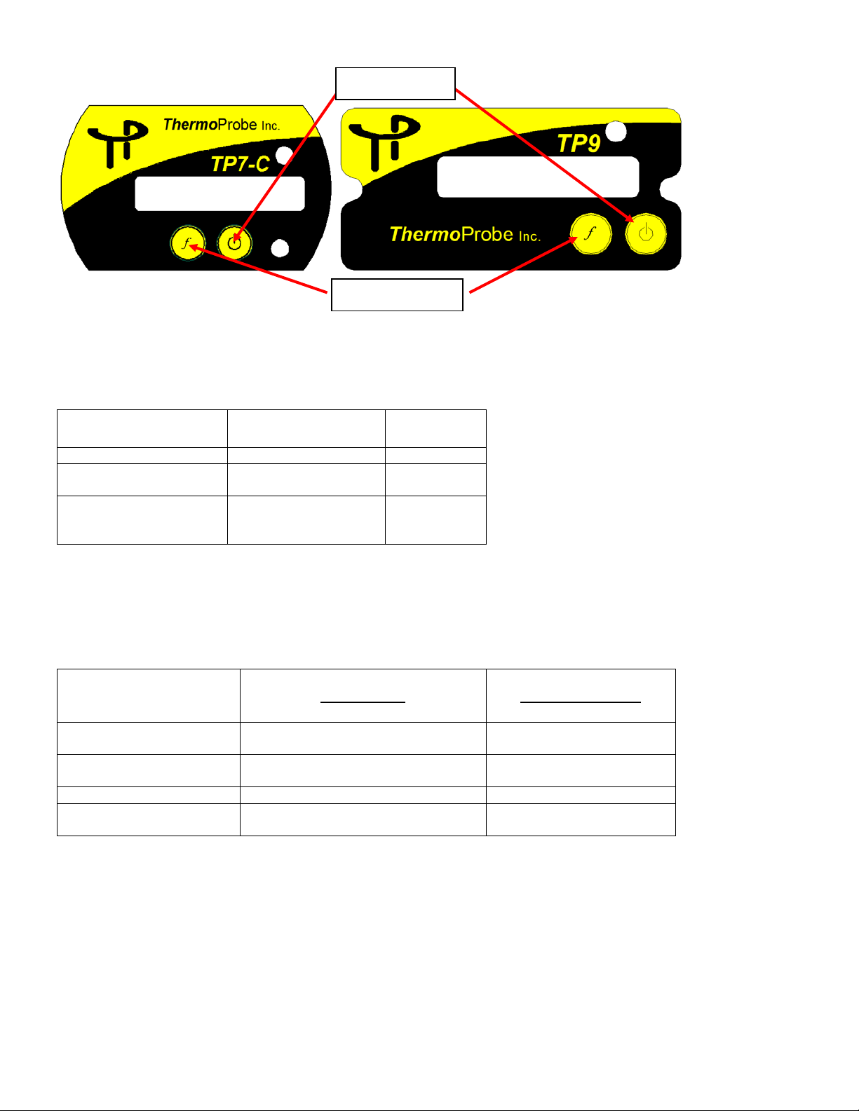
USER INTERFACE
One quick push
Power On
Two quick presses
Hold and Release
“LiSt”
“rEAd 1, 78.2 F”, “rEAd 2,
74.4 F”, etc.
“At”
“C-F”
Changes units
“76.3 F” or “24.6 C”
“dEC”
Changes units resolution (0.1 or 0.01)
“76.3 F” or “76.36 C”
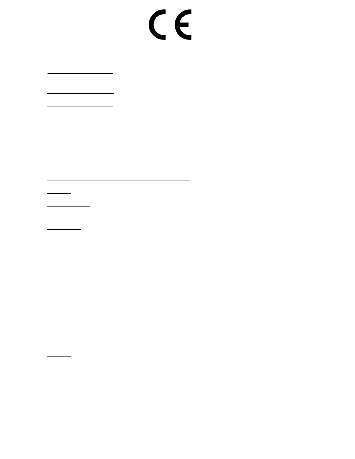
Power Button
Function Button
“Power” Button
Pressing the Power button once will turn on the device. The instrument will shut off automatically within 20 minutes.
Pressing the Power button twice (within 1 second) will save whatever reading is on the display.
Pressing and holding t he P o wer button will and shut the instrument off and clear all logged and averaged readings.
Power button
when display reads “oFF”
Operation Display
Saves current reading “LoggEd”
Power Off
(Clears Readings)
“oFF”
Function “f” button
Press and Hold the Function Button “f” to display options in a menu
format. When the desir ed function is displayed release the button.
Up to 10 readings can be saved and averaged.
Hold and Release when the
display reads:
Function (“f”) Example on Display
displays all saved readings
displays the average of all saved readings
“At, 76.3 F”
Backlight
When the instrument is operating in low-light conditions a photocell will detect this situation and permit the backlight to function.
Battery Check
When the voltage of the batteries is low, the device will indicate “Lo bAtt” on the display before resuming normal display functions.
When the batteries are low the backlight will not operate in order to conserve power while the user completes his operations. Replace
batteries as soon as possible in a safe location after “Lo bAtt” is noticed, this will ensure backlight operation, and avoid possible
malfunctioning. Do not attempt to calibrate the instrument if the “Lo bAtt” has been displayed since the new calibration values may
not be properly stored to memory.
11/2012, JK
Page 5
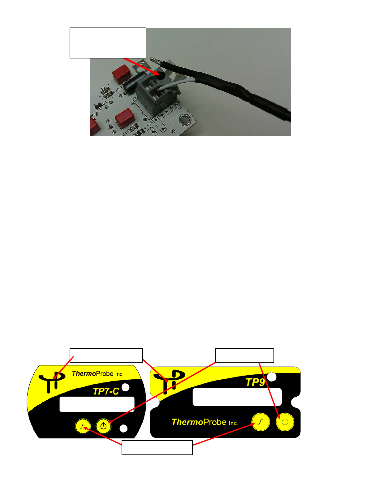
Negative Terminal
marking
Error Codes
ErrHI indicates the sensor is operating above its temperature limit, the Probe Assembly is open circuited from a cut or broken
section, or the cable is not properly inserted at the circuit board terminal. The most common cause is a damaged cable
ErrLO indicates the sensor is operating below its temperature limit, the Probe Assembly is short circuited due to a smashed or cut
section, or the cable wire polarity is reversed at the circuit board terminal. The most common cause is a damaged cable
nO rEAd -the user accessed "List" or "At" before saving temperatures.
.
.
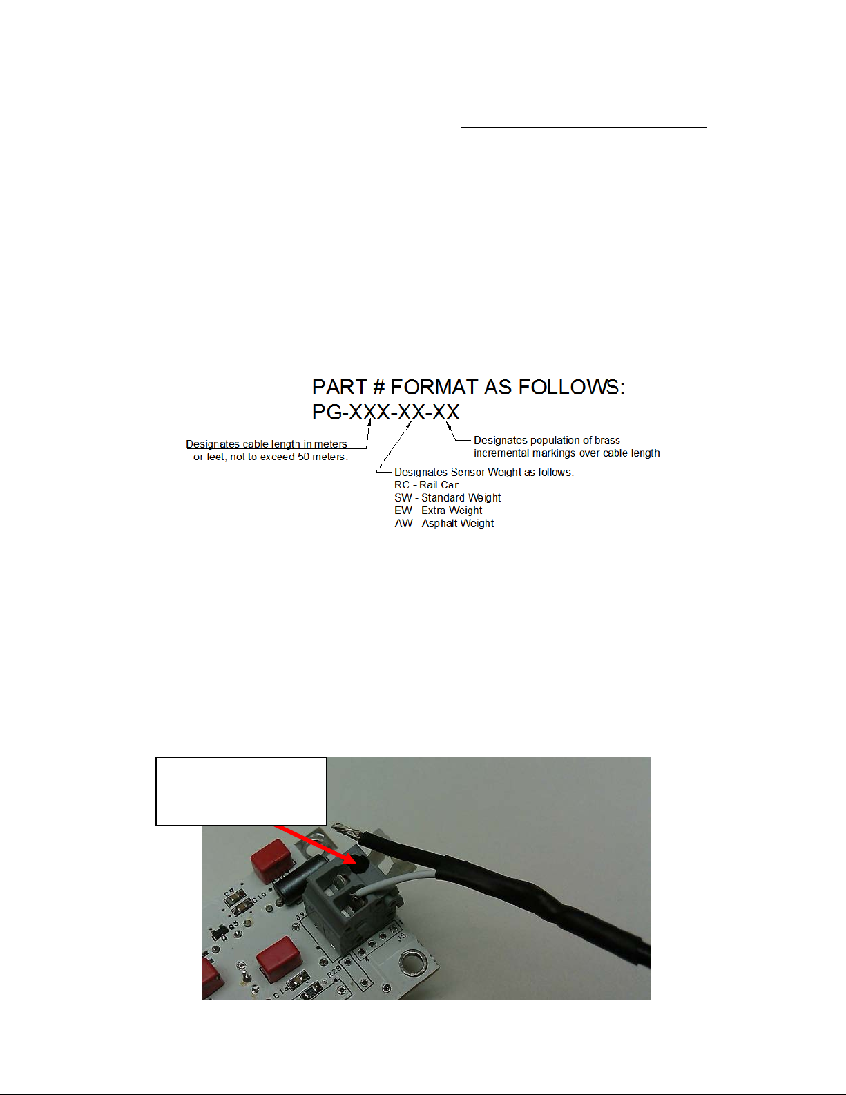
REPLACING THE PROBE ASSEMBLY
NOTES:
1) Replacement of the probe assembly requires re-ca l ibration of the device . R e pl a c e ment should only be done by e xperienced
personnel and if calibration equipment is available.
2) Please refer to IEC/EN 60079-19 wh e n making the repair
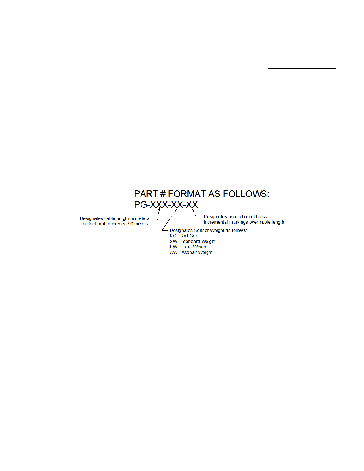
3) Only use replacement probe assemblies obtained from ThermoProbe, Inc. or one of its authorized distributors with part
specifications as follows:
a) First follow REPLACING BATTERY instructions a through c to remove batteries.
b) On the circuit board push the terminals clamps down and remove the wires noting the wire lead color code arrangement.
White – positive sensor wire
Black – negative sensor wire and sheild
c) Set the cover and circuit board aside and remove the strain relief knot in cable assembly.
d) Unwrap the cable from the assembl y and pull the cable free of the rubber grommet.
e) Insert the new cable wire through the rubber grommet and then pull several inches of cable slack past the grommet.
f) Tie a simple overhand knot in the cable at the grommet for strain relief and pull any slack through the grommet .
g) On the circuit board, push the terminal clamps down and insert the new wire leads making sure the black wire lead is installed in
the terminal indicated with black paint. (See Figure 1)
h) Reinstall the batteries and cover and re-spool the cable assembly.
i) Perform a calibration.
indicated by black
11/2012, JK
Page 6
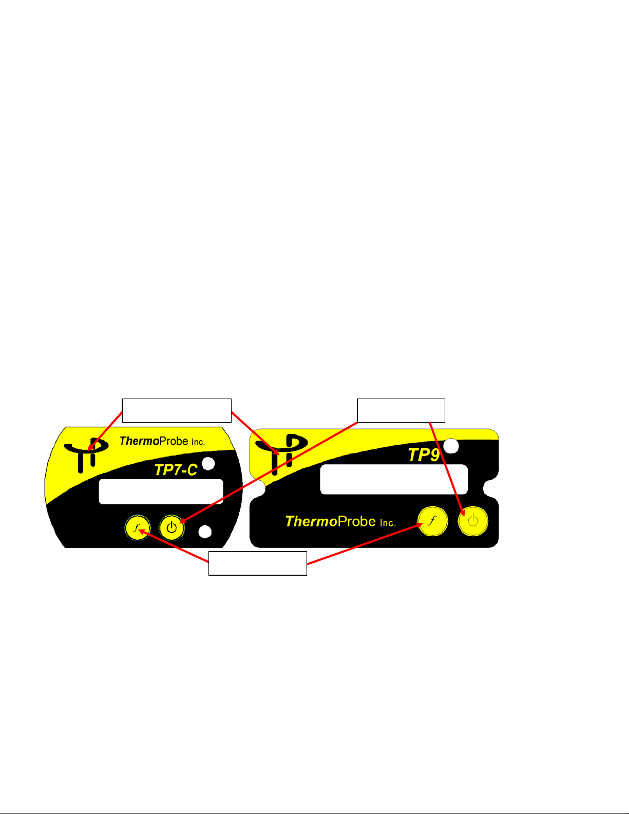
Figure 1: Probe Assembly Lead Attachment
Power Button
Function Button
Calibration Button
CALIBRATION PROCEDURE
• The calibration mode should only be accessed by qualified personnel with proper equipment; otherwise calibration integrity
may be compromised. Read the following instructions carefully.
• A 2-Point, 3-Point or a 4-point calibration can be performed. A third or fourth point is only necessary when high accuracy is
required at temperatures of 300°F and higher. You must have the proper equipment for every point of calibration.
• Do not attempt to calibrate the instrument if the “Lo bAtt” has been displayed since the new calibration values may not be
properly stored to memory.
• Refer to API 7.2 or another recognized standard for routine calibration verificati on re commendations.
• Calibration must not be performed in any environment considered to be hazardous.
Equipment needed:
• Ice Bath or other low temperature bath with certified reference thermometer.
• Warm to hot fluid bath between 20°C (approx 68°F), or higher up to 90°C (approx 194°F) with certified reference
thermometer. (see Note)*
• Optional high temperature oil bath at about 150°C/300°F and certified reference thermometer.
*Note for limited calibration: If entire range capability of instrument is not required, the 2 point high adjustment can be made at
a temperature relatively close to the common temperature of the liquid measured and accuracy will be maintained within the
limited range. For example: If liquid product to be measured is commonly less than 38°C (approx. 100°F), then a “high point”
calibration can be made near that temperature. Temperature accuracy above this calibration point cannot be assured.
11/2012, JK
Page 7

TThheerrmmooPPrroobbee,, IInncc..
To calibrate proceed with the following steps:
1. A hidden Calibration Button is located on the front overlay underneath the ThermoProbe logo (see diagram above).
While the instrument is on, first press and hold the “f” Button, and then press and hold the hidden Calibration Button until the
display scrolls through the options 2Pt CAL, 3PtCAL, 4PtCAL, CAnCEL. When the desired option is displayed, release the
buttons.
The Calibration Mode can be exited in two ways. If the user is not ready to enter the calibration mode, the CAnCEL option can be
chosen. If a user needs to end a calibration before completing it then STEP 3 below provides an option to safely exit the operation
and revert to previously stored calibration values.
2. The device is now in calibration mode.
The last character on the right side of the LCD will now be blinking “A” representing the lowest temperature calibration point.
“b” = the next higher temperature point
“C” = the next higher temperature point (only used in 3-point calibration or 4-point calibration mode)
“d” = the highest temperature point (only used in 4-point calibration mode)
While at each temperature calibration point the arrows will flash 3 times when the temperature reading stabilizes.
Calibration can be performed to hundredths of a degree.
The “On” Button increases the display reading, the “f” Button decreases the display reading.
Holding the “On” Button or the “f” Button adjusts 0.1 degrees increments.
Momentary Presses of the “On” Button or the “f” Button for less than 0.5 seconds adjusts 0.01 degrees for every press.
When you leave calibration mode the display remains in hundredths for that session only to allow you to re-check the temperatures.
Once you have turned the device off, the display will only show in tenths.
3. Once the temperature has stabilized, using a certified reference device check the actual temperature in the bath and use the “On”
Button or the “f” Button to adjust the device to the actual temperature. The “On” button will decrement the readings and the “f”
Button will increment the reading. Once the device temperature matches the actual temperature, press the Calibration Button to
save the setting. The display will scroll "SAUE" or “CAnCEL”. If the “SAUE” option is chosen the blinking letter will chang e to
represent the next temperature level (A => b). If the “CAnCEL” option is chosen then the calibration procedure is exited and the
prior calibration values are re-activated.
4. Move the probe to the next bath and repeat step 3. After you save the highest temperature point the display will flash "rEAdY"
and the new calibration settings will be in effect. The buttons will now resume their normal operating functions. The calibration
settings are saved to flash memory when the device is turned off. The unit will not turn off automatically, manually turning the unit
off saves the calibration data.
Calibration Error Codes
1. nO CAL - This is seen after the instrument is turned on when no calibration data has been saved yet. The device must be
calibrated before using.
2. CAL Err2 - This is seen after the instrument is turned on when there is a flash memory error or the calibrations data is corrupted.
When this error is displayed the device will inaccurately display temperatures without using any calibration data. This error probably
indicates a device error. The user should contact the distributor or ThermoProbe, Inc.
3. CAL Err3 - This is seen after the instrument is turned on when calibrations data reads OK, but is invalid. This could be an error in
calibrating the device. When this error is displayed the device will read temperatures without using any calibrations data. This error
could occur as a result of not saving the low or mid temperature before moving the device to the next bath during calibration. The
device should be recalibrated.
11/2012, JK
Ensure that your calibration efforts are saved by shu tting the instrument off now.
112A JETPORT DR.
PEARL, MS 39208
Tel: +1 601.939.1831
Fax: +1 601.355.1831
sales@thermoprobe.net
www.thermoprobe.net
Page 8
DECLARATION OF CONFORMITY
Apparatus Identification ThermoProbe Inc. Models TP7-C, TP9, TL1-A, TL1-W and TL1-R
Portable Digital Thermometers
Apparatus Classification
Statement of Conformity
Based on sample product test results using approp ri ate standards (Industrial environment), and in
accordance with the following EC Directiv es, ThermoProbe Inc. hereby declares the ThermoProbe Inc.
Models TP7-C, TP9, TL1-A, TL1-W and TL1-R to be in conformity with:
EC ATEX Directive 94/9/EC, Equipment or Protective System
intended for use in Potentially Explosive Atmospheres.
Sample Product Testing for ATEX
Tested By
Standards Used
EN 60079-11: 2007
Report ID
Manufacturer
112A Jeport Dr.
Pearl, MS 39208
President
DEMKO
EN 60079-0: 2009
11K04891
ThermoProbe Inc.
Measurement Equipment
Luke Bartkiewicz
10/5/12 JK
Page 9

GUIDE D'UTILISATION - TP7C ET TP9
INTRODUCTION
Ce manuel décrit le fonctionnement de base, l'utilisation et les consignes de sécurité d'un thermomètre numérique portable modèle
TP7C ou TP9. Ces instruments ThermoProbe s'utilisent dans les zones dangereuses (inflammables) et non dangereuses au sec et à des
températures ambiantes comprises entre -20 et 40 °C. Les instruments ne sont pas destinés à une utilisation dans des installations
extérieures permanentes et ils n'ont pas été prévus ni testés pour une utilisation en présence de glace.
doivent être utilisés pour les cas où l'équipement pourra être exposé à des contraintes externes excessives (par ex. vibrations, chaleur,
chocs, etc.).
D'autres moyens de protection
CONSIGNES DE SÉCURITÉ - AVANT L'UTILISATION
Les thermomètres ThermoProbe sont destinés à une utilisation sans danger dans des lieux dangereux (potentiellement inflammables
ou explosifs). L'utilisateur devra avoir connaissance des consignes de sécurité correspondant à son travail.
a) L'inspecteur devra bien connaître les produits à mesurer et les précautions à prendre avec le produit à mesurer.
b) L'instrument devra être contrôlé pour permettre le dépistage de défauts sévères, s'assurer que rien ne manque (notamment le câble
de mise à la terre), vérifier l'état des piles, etc. Si nécessaire, vérifier la précision de la mesure. En cas de défauts, l'instrument ne
devra pas être utilisé tant qu'il n'aura pas été réparé.
c) L'instrument, surtout le câble et la sonde, devra être nettoyé à la fois pour des raisons de sécurité et pour en faciliter l'utilisation.
d) L'emplacement physique de la mesure devra être évalué pour peser les risques primaires et secondaires.
e) L'alimentation doit être coupée avant toute maintenance.
f) Le remplacement de composants autres que les piles risque de compromettre la certification ATEX/IECEx et devra uniquement
être confié à Thermoprobe ou l'un de ses prestataires de service qualifiés. Voir aussi la section « Réparateurs agréés ».
g) Pour réduire le risque d'incendie ou d'explosion, cet appareil doit être mis à la terre à la cuve conformément à la clause 6.3.2 e),
IEC/EN 60079-14 avant et durant son introduction dans la cuve et cette mise à la terre devra persister jusqu'au retrait complet de la
cuve.
h) L'instrument devra être mis à la terre en utilisant la connexion prévue à cet effet chaque fois qu'une atmosphère dangereuse est
possible et dans les situations où réside l’éventualité d’une charge électrostatique notamment durant
câble du thermomètre ou le remplissage ou la vidange de la cuve.
ATTENTION : Si une quelconque partie de l'instrument accumule une charge électrostatique à un endroit potentiellement dangereux,
suivez les politiques de l'entreprise en matière de tests et d'évacuation de tous les gaz dangereux des lieux avant d'essayer de mettre à
la terre l'instrument. Si cela n'est pas possible, attendre la dissipation naturelle des charges de l'instrument avant d'essayer de le mettre
à la terre. En fonction de l'atmosphère, cette dissipat ion pourra prendre quelques heures.
le déroulement/l'enroulement du
MISE EN GARDE
Problèmes liés aux substances et environnements agressifs : Attention aux subst ances agressives pou vant nécessiter une pr ot e c tion
supplémentaire. La soude caustique et les substances très acides ou basiques éroderont le clip et la câble de mise à la terre en
aluminium et en cuivre. L'ensemble capteur-câble a des surfaces externes en inox et polymère fluoré. Une exposition à une chaleur
excessive peut faire fondre les composants en plastique de l'instrument.
11/2012, JK
Page 10
Homologations de sécurité pour les modèles TP7C et TP9 :
Zone dangereuse
Zone 0 ‘ia’
Zone dangereuse
Zone 1 ‘ib’
Câble de la sonde
Mise à la terre
II 2 (1) G Ex ib [ia] IIB T4
Normes applicables : Agence ou désignation de sécurité
IEC 60079-0:2007 Ed. 5 IECEx
IEC 60079-11:2006 Ed. 5 IECEx
EN 60079-0: 2009 Europe : ATEX
EN 60079-11:2007 Europe : ATEX
SÉCURITÉ INTRINSÈQUE
Un équipement intrinsèquement sûr correspond à un « équipement et câblage incapables de décharger une énergie électrique ou
thermique suffisante dans des conditions normales ou anormales pour causer l'inflammation d'un mélange atmosphérique da ngereux
spécifique dans sa concentration la plus facilement inflammable ». (ISA-RP12.6) Pour cela, il suffit de limiter l'alimentation
disponible à l'équipement électrique dans la zone dangereuse à un niveau inférieur au seuil d'inflammation des gaz.
Pour qu'un départ de feu ou une explosion soit possible, la présence d'un combustible, d'oxygène et d'une source d'inflammation est
obligatoire. Un système intrinsèquement sûr suppose la présence du combustible et d'oxygène dans l'atmosphère, mais le système est
conçu de sorte à empêcher que l'énergie électrique ou thermique dégagée par une boucle d'instrument particulière ne soit jamais assez
importante pour causer une inflammation.
Application aux lieux dangereux
TP7C/TP9 :
Sonde de
température
Corps de
l'instrument TP
Zone 0 : lieu où des concentrations de gaz, vapeurs ou liquides inflammables peuvent exister tout le temps ou pendant de longues périodes dans des conditions
normales d'utilisation.
Zone 1 : lieu où des concentrations de gaz, vapeurs ou liquides inflammables peuvent exister de manière épisodique dans des conditions normales d'utilisation.
11/2012, JK
Page 11

REMPLACEMENT DES PILES
AVERTISSEMENT :
• Les piles doivent être changées dans un lieu non dangereux.
• Les piles doivent être du type correct approuvé.
• Les piles doivent être installées dans le bon sens en veillant à aligner le pôle (+) sur le symbole (+) gravé dans le
compartiment des piles.
• Ne pas mélanger des piles neuves avec des piles usagées. Ne pas mélanger les piles de fabricants différents.
• Ne pas installer les piles en inversant la polarité étant donné qu'une pile risque d'en charger une autre.
a) S'assurer que l'instrument n'est pas dans une zone dangereuse.
b) Enlever les 3 vis qui fixent le couvercle avant sur le TP7C ou les 2 vis qui fixent le couvercle avant sur le TP9.
c) Enlever le dispositif de retenue des piles, pousser une pile vers le contact à ressort et soulever la pile du support, puis enlever
l'autre pile.
d) Installer chaque pile dans le bon sens en veillant à aligner le pôle (+) sur le symbole (+) gravé dans le compartiment des piles.
c) Remettre en place le dispositif de retenue et le couvercle.
Les piles CERTIFIÉES pour les modèles TP9 et TP7C sont les suivantes :
Fabricant Type Numéro de référence
Duracell A A ( L R6) alcaline MN1500
Panasonic AA (LR6) alcaline LR6XWA
GP (Gold Peak) AA (LR6) alcaline GP15A
PROCÉDURES DE MESURE
Voir sur www.thermoprobe.net
contacter le distributeur le plus proche ou ThermoProbe Inc. Se reporter à la norme sur les mesures de l'American Petroleum
Institute, chapitre 7.2.
Une fois la température stabilisée, les flèches vers le haut et le bas s'affichent.
Si vous voulez enregistrer la température pour calculer la moyenne, appuyer rapidement deux fois sur la touche Marche
L'enregistrement d'un relevé est confirmé par l'affichage de « LoggEd ». Si « ------- » s'affiche, le relevé n'a pas été enregistré en
raison d'une température non stabilisée. La température en cours se réaffiche ensuite, indiquant que l'appareil est prêt à prendre le
relevé suivant.
Une fois que vous avez pris tous les relevés nécessaires à votre opération, la touche « f » peut servir à afficher (LiSt) tous les relevés
enregistrés et à calculer la moyenne (At) des températures enregistrées. Documenter les relevés et la température moyenne avant de
mettre l'appareil hors tension.
Les relevés enregistrés et la moyenne ne sont pas enregistrés lors de la mise hors tension de l'instrument. (Remarque : L'instrument se
met automatiquement hors tension 20 minutes après la dernière pression sur une touche.)
la vidéo sur l'utilisation correcte de cet instrument. Pour les noms des installations de formation,
.
RÉPARATEURS AGRÉÉS
Il est recommandé de confier toute maintenance dépassant le cadre de ce manuel à ThermoProbe, Inc. ou à l’un de ses distributeurs
agréés.
11/2012, JK
Page 12

INTERFACE UTILISATEUR
Une pression rapide
Mise sous tension
Deux pressions rapides
Enregistrement du relevé
en cours
Maintenir et Relâcher
Maintenir et Relâcher lorsque
LiSt
« rEAd 1, 78.2 F », « rEAd 2,
74.4 F », etc.
At
Affichage de la moyenne de tous les
relevés enregistrés
C-F
Changement d'unités
« 76.3 F » ou « 24.6 C »
Changement de résolution d'unité (1 ou 2
chiffres après la virgule)
Touche Marche
Touche de fonction
Touche Marche
Une pression sur la touche Marche met l'instrument sous tension. L'instrument s'arrête automatiquement en 20 minutes.
Deux pressions sur la touche Marche (à 1 seconde d'intervalle) enregistre le relevé affiché.
Une pression maintenue sur la touche Marche arrête l'instrument et efface tous les relevés et moyennes enregistrés.
Touche Marche
quand « oFF » s'affiche
Opération Message affiché
LoggEd
Mise hors tension
(efface les relevés)
oFF
Touche de fonction « f »
Appuyer sans relâcher sur la touche de fonction « f » pour afficher les options sous la forme d'un menu.
Une fois que la fonction souhaitée s’affiche, relâcher la touche.
Au maximum, 10 relevés peuvent être enregistrés et combinés pour calculer la moyenne.
s'affiche le message :
dEC
Fonction (« f ») Exemple affiché
Affichage de tous les relevés enregistrés
« At, 76.3 F »
« 76.3 F » ou « 76,36 C »
Rétroéclairage
Lorsque l'instrument fonctionne dans des conditions de faible luminosité, une cellule photoélectrique détectera cette situation et
permettra le fonctionnement du rétroéclairage.
Contrôle des piles
Lorsque la tension des piles est basse, l'instrument affichera le message « Lo bAtt » avant de repasser à un affichage normal.
Lorsque la charge des piles est faible, le rétroéclairage ne fonctionne pas afin d'économiser les piles pendant que l'utilisateur finit
d'exécuter ses opérations. Remplacer les piles dans un endroit sûr le plus tôt possible après l'affichage du message « Lo bAtt » afin de
garantir le fonctionne ment du rétroéclaira ge e t éviter tout risque de dysf on c tionnement. Ne pas essa y e r d'étalonner l'instrument si
11/2012, JK
Page 13
« Lo bAtt » s'affiche dans la mesure où il est possible que les nouvelles valeurs d'étalonnage ne soient pas correctement mises en
mémoire.
Codes d'erreur
ErrHI indique que le capteur fonctionne au-dessus de sa limite de température, que le circuit de la sonde s'est ouvert (section coupée
ou cassée) ou que le câble n'est pas correctement inséré dans la borne de la carte de circuits imprimés.
La cause la plus courante est
un câble endommagé.
ErrLO indique que le capteur fonctionne au-dessous de sa limite de température, qu'il y a eu un court-circuit de sonde (section
écrasée ou coupée) ou que la polarité du câble est inversée au niveau de la borne de la carte de circuits imprimés.
La cause la plus
courante est un câble endommagé.
nO rEAd - l'utilisateur a accédé à « List » ou à « At » avant l'enregistrement des températures.
REMPLACEMENT DE LA SONDE
REMARQUES :
1) Le remplacement de la sonde exige le réétalonnage de l'instrument. Le remplacement doit uniquement être confié à un
personnel compétent et à condition qu'un équipement d'étalonnage soit disponible.
2) Durant la réparation, se reporter à IEC/EN 60079-19.
3) Utiliser uniquement des sondes de rechange proposées par ThermoProbe, Inc. ou l’un de ses distributeurs agréés avec les
spécifications suivantes :
a) Suivre les instructions a à c de la section « REMPLACEMENT DES PILES » pour enlever les piles.
b) Sur la carte de circuits imprimés, abaisser les pinces des bornes et enlever les fils en notant l'arrangement des codes couleur.
Blanc – fil de capteur positif
Noir – fil de capteur négatif et blindage
c) Mettre le couvercle et la carte de circuits de côté et enlever le nœud anti-tension sur le câble.
d) Dérouler le câble de l'ensemble et le dégager de l'œillet en caoutchouc.
e) Enfiler le câble neuf dans l'œillet en caoutchouc, puis éliminer le mou du câble en tirant sur plusieurs centimètres au-delà de
l'œillet.
f) Faire un nœud d'arrêt si mple sur le câble au nivea u de l'œillet en guise de nœud a nt i-tension et éliminer tout le mou à travers
l'œillet.
g) Sur la carte de circuits, abaisser les pinces des bornes et insérer les fils neufs en veillant à installer le fil noir dans la borne portant
la marque noire. (Figure 1)
h) Remettre les piles et le couvercle, puis rembobiner le câble.
i) Effectuer un étalonnage.
11/2012, JK
Page 14
Touche Marche
Touche de fonction
Touche d'étalonnage
Borne négative
indiquée par une
marque noire
Figure 1 : Branchement des fils de la sonde
PROCÉDURE D'ÉTALONNAGE
• Le mode Étalonnage est uniquement accessible à un personnel qualifié doté de l'équipement correct ; sinon, l'intégrité de
l'étalonnage risque d'être compromise. Lire attentivement les instructions suivantes.
• Un étalonnage à 2, 3 ou 4 points est possible. Un troisième ou quatrième point est nécessaire uniquement lorsqu'une haute
précision est requise à 149 °C et plus. Vous devez avoir l'équipement adéquat pour chaque point d'étalonnage.
• Ne pas essayer d'étalonner l'instrument si « Lo bAtt » s'affiche dans la mesure où il est possible que les nouvelles valeurs
d'étalonnage ne soient pas correctement mises en mémoire.
• Pour les procédures de vérification d'étalonnage de routine recommandées, se reporter à la norme API 7.2 ou une autre
norme reconnue.
• L'étalonnage ne doit pas avoir lieu dans un environnement jugé dangereux.
Équipement nécessaire :
• Bain de glace ou autre bain basse température avec thermomètre de référence certifié.
• Bain chaud à très chaud entre 20 et 90 °C environ avec thermomètre de référence certifié. (voir Remarque)*
• Bain d'huile haute température en option à 150 °C environ avec thermomètre de référence certifié.
*Remarque pour un étalonnage limité : Si la capacité complète de l'instrument n'est pas requise, l'ajustement « haut » à 2 points
peut être effectué à une température relativement proche de la température courante du liquide mesuré et la précision sera
maintenue dans l'intervalle limité. Exemple : Si un produit liquide à mesurer est le plus souvent à moins de 38 °C, un étalonnage
à « points hauts » pourra être effectué près de cette température. La précision de température au-delà de ce point d'étalonnage ne
peut être garantie.
11/2012, JK
Page 15

Procéder comme suit pour étalonner l'instrument :
TThheerrmmooPPrroobbee,, IInncc..
: +1
1. La touche d'étalonnage se trouve dissimulée sous le cache avant, sous le logo ThermoProbe (voir le diagramme ci-dessus).
Lorsque l'instrument est sous tension, appuyer et maintenir enfoncée la touche « f », puis appuyer en continu sur la touche
d'étalonnage cachée jusqu'à ce que les options suivantes défilent sur l'affichage : 2Pt CAL, 3PtCAL, 4P tC AL , C AnCEL. Une fois
que l'option souhaitée s’affiche, relâcher les touches.
Pour quitter le mode Étalonnage, procéder de l'une des deux manières suivantes. Si l'utilisateur n'est pas prêt à accéder au mode
Étalonnage, il peut sélectionner l'option CAnCEL. Si l'utilisateur doit arrêter l'étalonnage avant terme, l'ÉTAPE 3 ci-dessous permet
de quitter en toute sécurité l'opération et de rétablir les valeurs d'étalonnage précédemment stockées.
2. L'instrument est désormais en mode Étalonnage.
Le dernier caractère sur la droite de l'affichage est un A clignotant, indiquant le point d'étalonnage de température le plus bas.
b = point d'étalonnage de te mpérature supérieur suivant
C = point d'étalonnage de te mpérature supérieur suivant (uniquement uti lisé en mode Étalonnage à 3 o u 4 points)
d = point d'étalonnage de température le plus haut (uniquement utilisé en mode Étalonnage à 4 points)
À chaque point d'étalonnage de température, les flèches clignotent 3 fois une fois le relevé de température stabilisé.
L'étalonnage peut être effectué en centièmes de degré.
La touche « Marche » augmente le relevé affiché ; la touche « f » le réduit.
Une pression maintenue sur la touche « Marche » ou « f » permet un ajustement par incréments de 0,1 degré.
Des pressions momentanées sur la touche « Marche » ou « f » pendant moins de 0,5 seconde permet un ajustement par incréments
de 0,01 degré à chaque pression.
Lorsque l'utilisateur quitte le mode Étalonnage, l'affichage reste affiché en centièmes pour cette session uniquement pour lui
permettre de revérifier les températures. Une fois l'instrument hors tension, l'affichage montrera uniquement les dixièmes.
3. Une fois la température stabilisée, utiliser un thermomètre de référence certifié pour vérifier la température du bain et utiliser la
touche « Marche » ou « f » pour ajuster l'instrument à la température en cours. La touche « Marche » diminue le relevé ; la touche
« f » l'augmente. Une fois que la température de l'instrument correspond à la température en cours, appuyer sur la touche
d'étalonnage pour enregistrer le réglage. L'affichage alterne entre SAUE et CAnCEL. Si l'utilisateur choisit l'option SAUE, la
lettre clignotante change pour représenter le niveau de température suivant (A => b). Si l'utilisateur choisit l'option CAnCEL, la
procédure d'étalonnage est annulée et les valeurs d'étalonnage précédentes sont rétablies.
4. Transférer la sonde dans le bain suivant et répéter l'étape 3. Après avoir enregistré le plus haut point de température, rEAdY
clignote sur l'affichage et les nouveaux réglages d'étalonnage prennent effet. Les touches se remettent à fonctionner normalement.
Les réglages d'étalonnage sont enregistrés dans la mémoire Flash à la mise hors tension de l'instrument. L'instrument ne se met pas
automatiquement hors tension ; la mise hors tension manuelle de l'instrument enregistre les données d'étalonnage.
S'assurer que les valeurs d'étalonnage sont enregistrées lors de la mise hors tension de l'instrument.
Codes d'erreur d'étalonnage
1. nO CAL - Ce message s'affiche après la mise sous tension de l'instrument quand aucune donnée d'étalonnage n'a encore été
enregistrée. L'instrument doit être étalonné avant utilisation.
2. CAL Err2 - Ce message s'affiche après la mise sous tension de l'instrument quand il y a une erreur de mémoire Flash ou que les
données d'étalonnage sont corrompues. Lorsque cette erreur s'affiche, l'instrument affiche des températures erronées sans utiliser de
données d'étalonnage. Cette erreur indique probablement une erreur de l'instrument. L'utilisateur doit contacter le distributeur ou
ThermoProbe, Inc.
3. CAL Err3 - Ce message s'affiche après la mise sous tension de l'instrument quand les données d'étalonnage sont indiquées comme
étant correctes alors qu'elles ne le sont pas. Il peut s'agir d'une erreur d'étalonnage de l'instrument. Lorsque cette erreur s'affiche,
l'instrument fournit des températures sans utiliser de données d'étalonnage. Cette erreur est possible suite au non-enregistrement de la
température basse ou intermédiaire avant de passer au bain suivant durant l'étalonnage. L'instrument doit être réétalonné.
11/2012, JK
112A JETPORT DR.
PEARL, MS 39208 USA
Téléphone
601.939.1831
Fax : +1 601.355.1831
sales@thermoprobe.net
www.thermoprobe.net
Page 16
DÉCLARATION DE CONFORMITÉ
Identification de l'appareil ThermoProbe Inc. Modèles TP7-C, TP9, TL1-A, TL1-W et
TL1-R Thermomètres numériques portables
Classification de l'appareil
Déclaration de conformité
Au vu des résultats de tests effectués sur un produit type en respectant les normes adéquates
(Environnement industriel) et conformément aux Directives CE, ThermoProbe Inc. déclare par la
présente que les modèles TP7-C, TP9, TL1-A, TL1-W et TL1-R ThermoProbe Inc. sont conformes à la :
Directive 94/9/EC ATEX CE, Matériel ou système de protection
à utiliser en présence d'atmosphères potentiellement explosives.
Test de produit type pour atmosphère explosive (ATEX)
Testé par
Normes utilisées
EN 60079-11 : 2007
ID de rapport
Fabricant
112A Jeport Dr.
Pearl, MS 39208
Président
DEMKO
EN 60079-0 : 2009
11K04891
ThermoProbe Inc.
Instrument de mesure
Luke Bartkiewicz
5/10/12 JK
Page 17

INSTRUCCIONES PARA EL USUARIO - TP7C y TP9
INTRODUCCIÓN
Este manual describe la función básica, las instrucciones de uso y seguridad para un termómetro digital portátil modelo TP7C o TP9.
Estos instrumentos de ThermoProbe están de stinados para su uso tanto en áreas peligrosas (inflamables) como en áreas que no son
peligrosas en condiciones secas a temperaturas ambientes entre -20 a 40 °C. Los instrumentos no están destinados para su uso en
instalaciones permanentes al aire libre y no están destinados ni probados en condiciones de hielo.
adicionales de protección donde equipo puede estar expuesto a tensiones externas excesivas (por ejemplo, vibraciones, calor,
impacto, etc.).
Se deben utilizar medios
INFORMACIÓN DE SEGURIDAD ANTES DE USAR
Los termómetros ThermoProbe están diseñados para un funcionamiento seguro en lugares peligrosos (potencialmente inflamables o
explosivos). El usuario debe tener un conocimiento práctico de las normas de seguridad adecuadas.
a) El inspector debe tener un conocimiento profundo de los productos que se medirán y debe conocer las precauciones de seguridad
que se deben tomar cuando se trabaja con el material que se medirá.
b) Se deberá comprobar si el instrumento tiene defectos graves, compruebe que este instrumento esté completo (incluido el cable de
puesta a tierra/enlace), tenga buenas baterías, etc. Si fuese necesario, compruebe la precisión de la medición. Si se detecta algún
defecto, el instrumento no se debe utilizar hasta que se hayan hecho las reparaciones.
c) El instrumento, especialmente el cable y la sonda, se debe limpiar tanto por razones de seguridad como para una mayor facilidad
de uso.
d) Se debe evaluar la ubicación de la medición física para determinar riesgos primarios y secundarios.
e) La fuente de alimentación se debe retirar antes de realizar cualquier mantenimiento.
f) El intercambio de los componentes además de las baterías puede comprometer la certificación de ATEX/IECEx y solo
Thermoprobe o uno de sus proveedores de servicios calificados realizará dicho intercambio. Consulte también la sección
“Reparación autorizada”.
g) Para reducir el riesgo de incendio o explosión, este dispositivo debe estar conectado al depósito de acuerdo con la cláusula 6.3.2
e), IEC/EN 60079-14, antes y durante la introducción en el depósito y se mantendrá unido hasta que se retire por completo del
depósito.
h) El dispositivo debe permanecer conectado a tierra mediante la conexión proporcionada siempre que se pueda presentarse un
ambiente peligroso, así como durante situaciones donde puede ocurrir una carga electrostática, como
del cable del termómetro o el llenado o vaciado del depósito.
PRECAUCIÓN: En el caso de que cualquier parte del instrumento se deba cargar electrostáticamente en un lugar potencialmente
peligroso, siga las políticas de la empresa para probar y despejar el área de cualquier gas peligroso antes de intentar conectar el
instrumento a tierra. Si esto no es posible, permita que haya tiempo suficiente para que el instrumento disipe de forma natural
cualquier carga antes de intentar conectarlo a tierra. Esto podría tardar varias horas, según el ambiente.
el desenrollamiento/enrollado
NOTA DE ORIENTACIÓN
Problemas con sustancias agresivas y ambientes: Sea consciente de las sustancias agresivas y de que pueda necesitar protección
adicional. La soda cáustica, las sustancias muy ácidas y básicas erosionarán el aluminio y la pinza de conexión a tierra de cobre y los
alambres. El conjunto sensor-cable tiene superficies externas de acero inoxidable y de material de fluoropolímero. La exposición al
calor excesivo puede fundir las piezas de plástico del instrumento.
11/2012, JK
Page 18

Aprobación de seguridad para TP7C y TP9:
Área peligrosa
Zona 0 ‘ia’
Área peligrosa
Zona 1 ‘ib’
Cable de la
Conexión a tierra
II 2 (1) G Ex ib [ia] IIB T4
Las normas aplicables son: Agencia o designación de seguridad
IEC 60079-0:2007 Ed. 5 IECEx
IEC 60079-11:2006 Ed. 5 IECEx
EN 60079-0: 2009 Europa: ATEX
EN 60079-11:2007 Europa: ATEX
SEGURIDAD INTRÍNSECA
El equipo de seguridad intrínseca se define como "el equipo y el cableado que es incapaz de liberar suficiente energía eléctrica o
térmica en condiciones normales o anormales para causar la ignición de una mezcla atmosférica específica peligrosa en su
concentración más fácil de ignición". (ISA-RP12.6) Esto se logra mediante la limitación de la cantidad de energía disponible para el
equipo eléctrico en el área peligrosa a un nivel por debajo del que se inflamarán los gases.
El combustible, el oxígeno y una fuente de ignición deben estar presentes para que ocurra un incendio o una explosión. Un sistema de
seguridad intrínseca supone que el combustible y el oxígeno están presentes en la atmósfera, pero el sistema está diseñado de manera
que la energía eléctrica o la energía térmica de un circuito cerrado en particular nunca puede ser lo suficientemente grande como para
provocar la ignición.
TP7C/TP9 Aplicación
de la ubicación peligrosa:
Sonda de
temperatura
TP Cuerpo del
instrumento
sonda
Zona 0: Cuando las concentraciones de vapores gases o líquidos inflamables pueden existir todo el tiempo o durante largos períodos en condiciones normales de
funcionamiento.
Zona 1: Cuando las concentraciones de vapores gases o líquidos inflamables pueden existir algunas veces en condiciones normales de funcionamiento.
11/2012, JK
Page 19

CÓMO REEMPLAZAR LA BATERÍA
ADVERTENCIA:
• Las baterías se deben cambiar en un área que no sea peligrosa.
• Las baterías deben ser del tipo correcto aprobado.
• Las baterías se deben instalar con la polaridad correcta asegurándose de que el extremo (+) de la batería esté alineado con el
símbolo (+) grabado en la caja de la batería.
• Las baterías nuevas no se deben mezclar con las baterías viejas. Las baterías no se deben mezclar con las baterías de otros
fabricantes.
• Las baterías no se deben instalar con la polaridad invertida, donde un vaso de la batería podría cargar otro vaso.
a) Asegúrese de que el instrumento esté en un área que no sea peligrosa.
b) Retire los 3 tornillos que sujetan la cubierta frontal del TP7C o los 2 tornillos que sujetan la cubierta frontal en el TP9.
c) Retire el dispositivo de sujeción de la batería, presione una batería hacia un contacto con el resorte y levante la batería desde el
soporte, y luego retire la batería restante.
d) Instale cada nueva batería asegurándose de que el extremo (+) de la batería esté alineado con el símbolo (+) grabado en la caja de
la batería.
e) Reemplace el dispositivo de retención y vuelva a instalar la cubierta.
CERTIFICADO Las baterías para el TP9 y el TP7C son las siguientes:
Fabricante Tipo Número de pieza
Duracell A A ( L R6) Alcalina MN1500
Panasonic AA (LR6) Alcalina LR6XWA
GP (Gold Peak) AA (LR6) Alcalina GP15A
PROCEDIMIENTOS DE MEDICIÓN
Consulte www.thermoprobe.net
distribuidor o ThermoProbe Inc. para obtener los nombres de las instalaciones de capacitación. Consulte la norma de medición del
Instituto Americano del Petróleo, Capítulo 7.2.
Cuando se haya estabilizado la temperatura, aparecerán las flechas hacia arriba y hacia abajo.
Si desea registrar la temperatura a los fines de realizar el promedio, rápidamente
veces. El reconocimiento de una lectura guardada se producirá con una indicación “LoggEd” (Registrada). Si la pantalla muestra
“-------“, entonces la lectura no se registró debido a una temperatura que no está estabilizada. La temperatura en tiempo real entonces
se volverá a visualizar nuevamente, lo que indica que la siguiente lectura está lista para tomarse.
Si ha completado todas las lecturas necesarias para su funcionamiento, el botón “f” (Función) se puede utilizar para “LiSt”
(Enumerar) todas las lecturas registradas y “At” (Promedio) el promedio de las temperaturas registradas. Documente sus lecturas y la
temperatura promedio antes de apagar el dispositivo.
Las lecturas y los promedios registrados no se guardan cuando el instrumento se apaga. (Nota: el instrumento se apagará
automáticamente 20 minutos después de presionar el último botón).
para obtener el vídeo sobre el uso correcto de este instrumento. Póngase en contacto con su
presione el botón “On” (de encendido) dos
REPARACIÓN AUTORIZADA
Se recomienda que ThermoProbe, Inc. o uno de sus distribuidores autorizados realice el servicio fuera del alcance de este manual.
11/2012, JK
Page 20

INTERFAZ DEL USUARIO
Una pulsación rápida
Encendido
Dos pulsaciones rápidas
Mantenga presionado y suelte
cuando la pantalla lee “oFF” (Apagado)
“rEAd 1, 78,2 °F” (lect ura 1, 25,6 °C);
etc.
“At” (Promedio)
muestra el promedio de todas las lecturas
guardadas
“°C - °F”
Cambia las unidades
“76,3 °F” o “24,6 °C”
Cambia la resolución de las unidades
(0,1 o 0,01)
Botón Power
Botón Function
Botón “Power” (Encendido)
Al presionar el botón Power (Encendido) una vez se encenderá el dispositivo. El instrumento se apagará automáticamente en 20
minutos.
Al presionar el botón Power (Encendido) dos veces (en un segundo) se guardará cualquier lectura que esté en la pantalla.
Al mantener presionado el botón Power (Encendido) se apagará el instrumento y se borrarán todas las lecturas registradas y
promediadas.
Botón Power (Encendido)
Apagado (Borra las lecturas) “oFF” (Apagado)
Operación Pantalla
Guarda la lectura actual “LoggEd” (Registrada)
Botón Function “f” (Función)
Mantenga presionado el botón Function “f” (Función) para que aparezcan las opciones en un formato de menú.
Cuando aparezca la función deseada, suelte el botón.
Se pueden guardar y promediar hasta 10 lecturas.
Mantenga presionado y suelte
cuando la pantalla indique:
“LiSt” (Enumerar)
“dEC”
muestra todas las lecturas guardadas
Function (“f”) Ejemplo en pantalla
“rEAd 2, 74,4 °F” (lectura 2, 23,5 °C) ,
“At (Promedio), 76,3 °F (24,6 °C)”
“76,3 °F” o “76,36 °C”
Retroiluminación
Cuando el instrumento está funcionando en condiciones de poca luz, una fotocélula detectará esta situación y permitirá que se active
la retroiluminación.
11/2012, JK
Page 21

Comprobación de la batería
Cuando el voltaje de las baterías es bajo, el dispositivo indicará “Lo bAtt” (Batería baja) en la pantalla antes de reanudar las
funciones normales de visualización. Cuando las baterías están bajas, la retroiluminación no funcionará con el fin de conservar la
energía mientras el usuario realiza sus operaciones. Reemplace las baterías tan pronto como sea posible en un lugar seguro después
de que se indique “Lo bAtt” (Baja batería). Esto asegurará el funcionamiento de la retroiluminación y evitará un posible mal
funcionamiento. No intente calibrar el instrumento si aparece “Lo bAtt” (Batería baja) dado que es posible que los nuevos valores de
calibración no estén guardados correctamente en la memoria.
Códigos de error
ErrHI: indica que el sensor está funcionando por encima del límite de la temperatura, el conjunto de sonda está en circuito abierto de
una sección cortada o rota, o el cable no está insertado correctamente en la terminal de la placa del circuito.
un cable dañado.
ErrLO: indica que el sensor está funcionando por debajo del límite de la temperatura, el conjunto de sonda está en cortocircuito
debido a una sección rota o cortada, o la polaridad de los hilos del cable está invertida en la terminal de la placa del circuito.
más común es un cable dañado.
nO rEAd (sin lecturas): el usuario accedió a "List" (Enumerar) o "At" (Promedio) antes de guardar las temperaturas.
La causa más común es
La causa
CÓMO REEMPLAZAR EL CONJUNTO DE SONDA
NOTAS:
1) El reemplazo del conjunto de sonda requiere una recalibración del dispositivo. Solo el personal experimentado debe realizar
el reemplazo y si se encuentra disponible el equipo de calibración.
2) Consulte IEC/EN 60079-19 cuando realice la reparación
3) Utilice solo los conjuntos de sonda de reemplazo obtenidos de ThermoProbe, Inc. o uno de sus distribuidores autorizados
con especificaciones de las piezas de la siguiente manera:
a) Primero siga las instrucciones de CÓMO REEMPLAZAR LA BATERÍA desde el punto a hasta el punto c para retirar las
baterías.
b) En la placa del circuito empuje las abrazaderas de las terminales y retire los cables teniendo en cuenta los códigos del color de las
terminales de alambre.
Blanco: cable positivo del sensor
Negro: cable negativo del sensor y blindaje
c) Coloque la cubierta y la placa del circuito a un lado y retire el nudo del aliviador de tensión en el conjunto del cable.
d) Desenrolle el cable desde el conjunto y tire del cable libre de la arandela de goma.
e) Inserte el nuevo cable a través de la arandela de goma y tire varios centímetros del cable más allá de la arandela.
f) Ate un nudo simple en el cable en la arandela para aliviar la tensión y retire la holgura sobrante a través de la arandela.
g) En la placa del circuito, empuje las abrazaderas de la terminal hacia abajo e inserte el nuevo cable asegurándose de que el cable
negro se instale en la terminal indicada con pintura de color negro. (Consulte la Figura 1)
h) Vuelva a instalar las baterías y la cubierta, y vuelva a enrollar el conjunto de cables.
i) Realice una calibración.
11/2012, JK
Page 22

Terminal negativa
marcada con color
negro
Figura 1: Acoplamiento principal del conjunto de sonda
PROCEDIMIENTO DE CALIBRACIÓN
• Solo el personal calificado con el equipo adecuado puede acceder al modo de calibración, en caso contrario puede verse
comprometida la integridad de la calibración. Lea atentamente las siguientes instrucciones.
• Se puede realizar una calibración de 2 puntos, 3 p u ntos o 4 puntos. Una cali bra c ión de 3 o 4 puntos solo es necesaria cuando
se requiere una alta precisión a temperaturas de 300 °F (148,8 °C) y superiores. Debe tener el equipo adecuado para cada
punto de calibración.
• No intente calibrar el instrumento si aparece “Lo bAtt” (Batería baja) dado que es posible que los nuevos valores de
calibración no estén guardados correctamente en la memoria.
• Consulte API 7.2 u otra n orma reconocida para obt e ner las recomendaciones de verificación de ca l ibración de rutina.
• La calibración no se debe realizar en cualquier ambiente considerado como peligroso.
Equipo necesario:
• Baño de hielo u otro baño a baja temperatura con termómetro de referencia con certificado.
• Baño de fluido de tibio a caliente entre 20 °C (aproximadamente 68 °F), o mayor, hasta 90 °C (aproximadamente 194 °F)
con termómetro de referencia con certificado. (consulte Nota)*
• Baño de aceite a alta temperatura opcional a aproximadamente 150 °C/300 °F y termómetro de referencia con certificado.
*Nota para calibraciones limitadas: Si no se requiere toda la capacidad de alcance del instrumento, se puede realizar el ajuste
elevado de 2 puntos a una temperatura relativamente cercana a la temperatura común del líquido medido, y la precisión se
mantendrá dentro del alcance limitado. Por ejemplo: Si el producto líquido que se medirá normalmente es menor que 38 °C
(aproximadamente 100 °F), entonces se puede realizar una calibración de "punto alto" cerca de esa temperatura. No se puede
garantizar una precisión de la temperatura por encima de este punto de calibración.
11/2012, JK
Page 23

Botón Power
Botón Function
Botón Calibration
Para calibrar proceda con los siguientes pasos:
1. Un botón Calibration (Calibración) se encuentra oculto en la superposición delantera debajo del logotipo de ThermoProbe
(consulte el diagrama anterior).
Cuando el instrumento está encendido, primero mantenga presionado el botón “f” (Función), y luego mantenga presionado el
botón Calibration (Calibración) hasta que la pantalla permita desplazarse a través de las opciones 2Pt CAL (Calibración de 2
puntos), 3PtCAL (Calibración de 3 puntos), 4PtCAL (Calibración de 4 puntos), CAnCEL (Cancelar). Cuando aparezca la
opción deseada, suelte los botones.
Se puede salir del modo de calibración de dos maneras. Si el usuario no está listo para entrar en el modo calibración, se puede elegir
la opción CAnCEL (Cancelar). Si un usuario debe finalizar una calibración antes de completarla, entonces el siguiente PASO 3
proporciona una opción para salir con seguridad de la operación y volver a los valores de calibración guardados previamente.
2. El dispositivo está ahora en el modo calibración.
El último carácter en el lado derecho de la pantalla LCD ahora estará parpadeando “A”, que representa el punto de calibración de
temperatura más bajo.
“b” = el punto de temperatura inmediatamente más alto
“C” = el punto de temperatura inmediatamente más alto (solo se utiliza en el modo de calibración de 3 puntos o de 4 puntos)
“d” = el punto de temperatura más alto (solo se utiliza en el modo de calibración de 4 puntos)
Mientras en cada punto de calibración de temperatura las flechas parpadearán 3 veces cuando la lectura de la temperatura se
estabilice.
La calibración se puede realizar a centésimas de grado.
El botón “On” (de encendido) aumenta la lectura de la pantalla, el botón “f” (Función) disminuye la lectura de la pantalla.
Al mantener presionado el botón “On” (de encendido ) o e l botón “f” (Función) ajusta inc re mentos de 0,1 grados .
Al presionar de manera momentánea el botón “On” (de encendido) o el botón “f” (Función) durante menos de 0,5 segundos ajusta
0,01 grados por cada pulsación.
Cuando sale del modo de calibración, la pantalla permanece en centésimas para esa sesión solo para permitir que vuelva a comprobar
las temperaturas. Una vez que haya apagado el dispositivo, la pantalla solo mostrará en décimas.
3. Una vez que se haya estabilizado la temperatura mediante un dispositivo de referencia con certificado, verifique la temperatura
real en el baño y utilice el botón “On” (de encendido) o el botón “f” (Función) para a justar el dispositivo a la temperatura real. El
botón “On” (de encendido) disminuirá las lecturas y el botón “f” (Función) incrementará la lectura. Una vez que la temperatura del
dispositivo coincida con la temperatura real, presione el botón Calibration (Calibración) p ara guardar la configuración. La
pantalla desplegará "SAVE" (Guardar) o “CAnCEL”(Cancelar). Si se elige la opción “SAVE” (Guardar), la letra que parpadea
cambiará para representar el siguiente nivel de temperatura (A => b). Si se elige la opción “CAnCEL” (Cancelar), entonces se sale
del procedimiento de calibración y se vuelven a activar los valores de calibración anteriores.
11/2012, JK
Page 24

4. Mueva la sonda al siguiente baño y repita el paso 3. Después de que guardó el punto de temperatura más alto, la pantalla
TThheerrmmooPPrroobbee,, IInncc..
parpadeará "rEAdY" (Listo) y las nuevas configuraciones estarán en vigencia. Los botones reanudarán ahora sus operaciones
normales de funcionamiento. Las configuraciones de calibración se guardan en la memoria flash cuando el dispositivo está apagado.
La unidad no se apagará automáticamente. Al apagar la unidad de forma manual se guardan los datos de calibración.
Asegúrese de que sus esfuerzos de calibración se guarden al apagar el instrumento.
Códigos de error de calibración
1. nO CAL (Sin calibración): esto se ve después de que el instrumento se enciende cuando no se guardó todavía ningún dato de
calibración. El dispositivo se debe calibrar antes de utilizar.
2. CAL Err2 (Error de calibración 2): esto se ve después de que el instrumento se enciende cuando hay un error en la memoria flash
o los datos de calibración están dañados. Cuando aparece este error, el dispositivo mostrará las temperaturas de manera imprecisa sin
utilizar los datos de calibración. Este error indica probablemente un error del dispositivo. El usuario debe ponerse en contacto con el
distribuidor o con ThermoProbe, Inc.
3. CAL Err3 (Error de calibración 3): esto se ve después de que el instrumento se enciende cuando los datos de las calibraciones se
leen bien, pero no es válido. Esto podría ser un error al calibrar el dispositivo. Cuando aparece este error, el dispositivo indicará las
temperaturas sin utilizar los datos de calibración. Este error pod ría ocurrir como result ado de no guardar la tempe ra t ur a baja o media
antes de mover el dispositivo al próximo baño durante la calibración. Se debe volver a calibrar el dispositivo.
112A JETPORT DR.
PEARL, MS 39208
Tel: +1 601.939.1831
Fax: +1 601.355.1831
sales@thermoprobe.net
www.thermoprobe.net
11/2012, JK
Page 25

DECLARACIÓN DE CONFORMIDAD
Identificación del aparato ThermoProbe Inc. Modelos TP7-C, TP9, TL1-A, TL1-W y TL1-R
Termómetros digitales portátiles
Clasificación del aparato
Declaración de conformidad
A partir de los resultados de la prueba del producto de m uestra según las normas adecuadas (ambiente
industrial), y de conformidad con las siguientes directivas de la CE, ThermoProbe Inc. decl ara por la
presente que los modelos TP7-C, TP9, TL1-A, TL1-W y TL1-R de ThermoProbe Inc. están de acuerdo
con:
Directiva ATEX de la CE 94/9/CE, Equipos o sistema de protección
para su utilización en atmósferas potencialme nte explosivas.
Prueba del producto de muestra para ATEX
Analizado por
Normas utilizadas
EN 60079-11: 2007
DEMKO
ID del informe 11K04891
Fabricante
112A Jeport Dr.
Pearl, MS 39208 USA
Presidente
ThermoProbe Inc.
Equipos de medición
EN 60079-0: 2009
Luke Bartkiewicz
10/5/12 JK
Page 26

РУКОВОДСТВО ПО ЭКСПЛУАТАЦИИ ЦИФРОВЫХ
ТЕРМОМЕТРОВ TP7C И TP9
ВВЕДЕНИЕ
В настоящем руководстве описаны основные функции переносных цифровых термометров моделей TP7C и TP9,
инструкции по их использованию и правила техники безопасности. Эти приборы, выпускаемые компанией ThermoProbe,
предназначены для использования в опасных (пожароопасных) и безопасных зонах с сухой атмосферой при температуре
окружающей среды от -20 до 40°C. Приборы не предназначены для использования в стационарных наружных установках.
Кроме того, они не испытывались и не предназначаются для эксплуатации в условиях обледенения. Дополнительные
средства защиты должны предусматриваться, если оборудование может подвергаться сильным внешним воздействиям
(например - вибрации, нагреву, ударным воздействиям и т.д.)
ПРАВИЛА ТЕХНИКИ БЕЗОПАСНОСТИ
Термометры производства компании ThermoProbe предназначены для безопасной работы в опасных зонах (пожароопасных
и взрывоопасных). Пользователь термометра должен знать соответствующие правила техники безопасности.
a) Инспектор должен хорошо знать свойства измеряемой среды и правила техники безопасности при работе с измеряемой
средой.
b) Прибор проверяется на наличие серьезных дефектов, также необходимо проверить комплектность прибора (включая
наличие заземляющего кабеля / кабеля выравнивания потенциала); убедиться в том, что батарейки не разряжены и т.д. При
необходимости проверить погрешность измерений. При обнаружении дефектов запрещается использовать прибор до их
устранения.
c) Прибор, в особенности кабель и датчик, должен быть чистым в целях безопасности и удобства использования.
d) Место измерений необходимо оценить с точки зрения непосредственных и второстепенных рисков.
e) Перед проведением технического обслуживания снять источник питания.
f) Замена комплектующих, кроме батарей, может привести к прекращению действия сертификата соответствия требованиям
ATEX/IECEx. Эти работы должны выполняться только представителями компании Thermoprobe или одного из ее
аттестованных провайдеров по техническому обслуживанию. См. также раздел «Разрешенный ремонт».
g) Для уменьшения опасности пожара или взрыва данный термометр перед установкой в емкости необходимо соединить с
ее стенкой для выравнивания потенциала в соответствии с требованиями п. 6.3.2 e) стандарта IEC/EN 60079-14. Это
соединение должно сохраняться во время перемещения прибора в емкость и нахождения в ней. Это соединение снимается
только после извлечения термометра из емкости.
h) Термометр должен оставаться подключенным к заземлению с помощью предусмотренных средств подключения при
использовании в опасной атмосфере и в условиях, при которых возможно возникновение электростатического заряда,
например, при разматывании / сматывании кабеля термометра и при заполнении / опорожнении емкости.
ОСТОРОЖНО! Если на какой-либо части прибора может образоваться электростатический заряд при нахождении прибора
в потенциально опасной зоне, выполнить разработанные компанией процедуры по проверке наличия и удаления опасных
газов из зоны установки прибора перед его подключением к заземлению. Если выполнить эти операции невозможно,
выдержать прибор в течение времени, достаточного для естественного исчезновения заряда, и только после этого
подключить прибор к заземлению. В зависимости от условий для этого может потребоваться несколько часов.
ПРИМЕЧАНИЕ
Использование для измерения агрессивных веществ и технологических сред: Учитывать наличие агрессивных веществ и
помнить о необходимости дополнительной защиты. Каустическая сода, сильно основные и сильно кислые вещества вызовут
разрушение алюминиевых и медных зажимов заземления и проводов. Внешние поверхности датчика и его кабеля
выполнены из нержавеющей стали или фторопласта. Сильный нагрев может привести к расплавлению пластиковых
компонентов прибора.
11/2012, JK
Page 27

Сертификаты безопасности для TP7C и TP9
Корпус
Опасная зона
Зона 1 ‘ib’
Кабель датчика
Заземление
Опасная зона
Зона 0 ‘ia’
II 2 (1) G Ex ib [ia] IIB T4
- Применяемые стандарты: Агентство или вид сертификации
IEC 60079-0:2007, 5 изд. IECEx
IEC 60079-11:2006, 5 изд. IECEx
EN 60079-0: 2009 Европа: ATEX
EN 60079-11:2007 Европа: ATEX
ИСКРОБЕЗОПАСНОСТЬ
Искробезопасное оборудование определяется как "оборудование и электрическая проводка, выполненные таким образом,
что создаваемый ими электрический разряд или тепловая энергия при нормальных или нештатных условиях эксплуатации
не могут воспламенить взрывоопасную среду, имеющую наиболее легко воспламеняющуюся концентрацию". (ISA-RP12.6).
Это достигается путем ограничения мощности, подводимой к электрооборудованию в опасной зоне, значением, при
превышении которого произойдет воспламенение газа.
Для возникновения пожара или взрыва необходимо присутствие топлива, кислорода и источника воспламенения.
Искробезопасная система предполагает присутствие топлива и кислорода в атмосфере, но система выполнена таким
образом, что электрический разряд или нагрев электрической цепи прибора не может вызвать воспламенение.
ИспользованиеTP7C/TP9
в опасной зоне:
Датчик
температуры
цифрового
термометра ТP
Зона 0, в которой горючие газы, пары или жидкости присутствуют постоянно или в течение длительного времени при нормальных условиях эксплуатации
в такой концентрации, что они могут образовывать с воздухом взрывоопасные смеси.
Зона 1, в которой горючие газы, пары или жидкости присутствуют в течение некоторого времени при нормальных условиях эксплуатации в такой
концентрации, что они могут образовывать с воздухом взрывоопасные смеси.
11/2012, JK
Page 28

Изготовитель
Тип
Номер детали
Duracell
Щелочная AA (LR6)
MN1500
Panasonic
Щелочная AA (LR6)
LR6XWA
GP (Gold Peak)
Щелочная AA (LR6)
GP15A
ЗАМЕНА БАТАРЕИ
ПРЕДУПРЕЖДЕНИЕ.
• Батареи должны заменяться в безопасной зоне.
• Должны использоваться батареи утвержденного типа.
• Батареи должны устанавливаться с соблюдением полярности. Полюс (+) батареи совмещается со стороной (+)
отсека для батареи.
• Новые батареи запрещается использовать вместе со старыми. Запрещается одновременно использовать батареи
разных изготовителей.
• При установке запрещается нарушать требуемую полярность, так как при этом одна батарея будет заряжать другую
батарею.
a) Убедиться в том, что прибор находится в безопасной зоне.
b) Отвернуть 3 или 2 винта, которыми крепится передняя крышка термометра TP7C или ТР9, соответственно.
c) Снять фиксатор батарей. Сдвинуть одну батарею в сторону пружинного контакта и извлечь ее из держателя. Затем
извлечь другую батарею.
d) Установить новые батареи с соблюдением полярности. Полюс (+) батареи совмещается со стороной (+) отсека для
батареи.
e) Установить на место фиксатор батарей и крышку.
СЕРТИФИЦИРОВАННЫЕ батареи для TP9 и TP7C:
ПРОЦЕДУРЫ ИЗМЕРЕНИЙ
Видеофильм, показывающий порядок применения данного прибора, выложен на сайте www.thermoprobe.net
по учебным центрам можно получить в компании ThermoProbe Inc. или у ее дистрибьютора. См. стандарт API по
измерениям, гл. 7.2.
После стабилизации температуры на индикаторе появятся стрелки ↑ и ↓.
Для регистрации температуры в целях ее усреднения дважды быстро нажать кнопку On
сохранения показаний на индикаторе появится подтверждающее сообщение «LoggEd». Если индикатор покажет “-------“, то
это значит, что показания не были сохранены, так как температура не стабилизировалась. Затем на индикаторе отобразится
текущая измеряемая температура, показывая, что прибор готов к регистрации нового значения.
После выполнения всех необходимых измерений можно использовать кнопку “f” для вывода “LiSt” (перечня) всех
зарегистрированных результатов и “At” для определения среднего значения. Записать зарегистрированные показания и
среднюю температуру до выключения прибора.
Зарегистрированные показания не сохраняются при выключении прибора. (Примечание: Прибор автоматически
выключается через 20 минут после последнего нажатия любой из кнопок).
. Для подтверждения
. Информацию
РАЗРЕШЕННЫЙ РЕМОНТ
Работы по обслуживанию, которые не описаны в настоящем руководстве, должны выполняться сотрудниками компании
ThermoProbe, Inc. или ее уполномоченными дистрибьюторами.
11/2012, JK
Page 29

ПОЛЬЗОВАТЕЛЬСКИЙ ИНТЕРФЕЙС
Кнопка “Power”
(включение питания)
Сообщение на
индикаторе
Быстрое однократное
нажатие
Быстрое двукратное
нажатие
Сохранение текущего
показания
Нажать и отпустить
индикаторе
“rEAd 1, 78.2 F”, “rEAd 2, 74.4
F” и т.д.
Вывод рассчитанного среднего значения
по всем сохраненным показаниям
“C-F”
Изменение единиц измерения
“76.3 F” или “24.6 C”
Изменение разрешения при выводе
показаний (0,1 или 0,01)
Кнопка включения питания
Функциональная кнопка
Кнопка “Power” (включение питания)
Для включения термометра нажать кнопку Power. Прибор автоматически выключится через 20 минут.
При двукратном нажатии на эту кнопку (в течение 1 с) сохраняется значение, отображаемое в данный момент на
индикаторе.
Для выключения прибора нажать кнопку Power и удерживать ее в нажатом положении. Это также приведет к стиранию всех
зарегистрированных показаний и рассчитанных средних значений.
Эксплуатация
Включение питания
“LoggEd”
при появлении “oFF” на
Выключение
(сброс показаний)
“oFF”
Функциональная кнопка “f”
Нажать и удерживать кнопку “f” для отображения предусмотренных опций в формате меню.
При появлении требуемой функции отпустить кнопку.
Возможно сохранение до 10 значений и расчет среднего значения.
Нажать и отпустить при
появлении на индикаторе
сообщения
“LiSt” Вывод всех сохраненных значений
“At”
“dEC”
Функция (“f”)
Пример сообщения на
индикаторе
“At, 76.3 F”
“76.3 F” или “76.36 C”
11/2012, JK
Page 30

Задняя подсветка
Если прибор работает в условиях пониженной освещенности, фотоэлемент определяет уровень освещенности и вводит в
действие подсветку.
Проверка батарей
При низком напряжении батарей на индикатор выводится сообщение “Lo bAtt” и затем индикатор возвращается в
нормальный режим. При низком напряжении подсветка не работает для сокращения энергопотребления с тем, чтобы
оператор мог закончить измерения. После появления сообщения “Lo bAtt” заменить батареи при первой возможности в
безопасной зоне. Это обеспечит нормальную работу подсветки и исключит возможные нарушения работы термометра. При
появлении сообщения “Lo bAtt” не рекомендуется выполнять калибровку прибора, так как параметры калибровки могут
сохраниться в памяти с ошибкой.
Коды ошибок
ErrHI указывает на превышение предела рабочей температуры датчика, обрыв цепи датчика или плохой контакт кабеля в
клеммах печатной платы.
ErrLO указывает на работу датчика при температуре ниже заданного диапазона, короткое замыкание цепи датчика из-за
повреждения изоляции или обрыва проводов или неправильную полярность подключения кабеля к печатной плате.
Наиболее вероятная причина – повреждение кабеля.
nO rEAd указывает на использование оператором функций "List" (перечень зарегистрированных значений температуры)
или "At" (расчет среднего значения) до сохранения результатов измерений.
Наиболее вероятная причина – повреждения кабеля.
ЗАМЕНА ДАТЧИКА
ПРИМЕЧАНИЯ:
1) После замены датчика необходимо выполнить калибровку термометра. Эта операция должна выполняться только
квалифицированным персоналом и только при наличии оборудования для калибровки.
2) Указания по выполнению этой операции см. в IEC/EN 60079-19.
3) Для замены использовать только датчики, полученные от ThermoProbe, Inc или одного из ее уполномоченных
дистрибьюторов. Условное обозначение (номер по каталогу) датчика будет следующим:
a) Вначале извлечь батареи, выполнив пп. а) – с) инструкции по ЗАМЕНЕ БАТАРЕЙ.
b) На печатной плате нажать на зажимы клемм и извлечь присоединенные провода, отметив цветовую кодировку выводов
проводов.
Белый провод – положительный провод датчика
Черный провод – отрицательный провод датчика и экран.
c) Отложить крышку и печатную плату. Снять узел разгрузки натяжения кабеля в сборе.
d) Размотать кабель и вытянуть его из резиновой втулки.
e) Пропустить новый кабель через резиновую втулку, так чтобы длина свободного участка кабеля после втулки составляла
несколько дюймов.
f) Завязать в кабеле у втулки простой узел для снятия напряжения и выбрать слабину кабеля, протащив его через втулку.
g) На печатной плате нажать на зажимы клемм. Вставить провода нового кабеля в клеммы. Удостовериться, что черный
провод подключен к клемме, имеющей черную маркировку. (См. рис. 1).
h) Установить на место батареи и крышку отсека батарей. Свернуть кабель в сборе.
i) Выполнить калибровку.
11/2012, JK
Page 31

Отрицательная
черную маркировку
клемма имеет
Рис. 1. Подключение кабеля датчика в сборе.
ПРОЦЕДУРА КАЛИБРОВКИ
• Калибровка должна выполняться только квалифицированным персоналом, с использованием соответствующего
оборудования; несоблюдение этих требований может привести к сбою калибровки. Внимательно прочитать
приведенные ниже инструкции.
• Можно выполнить калибровку по 2, 3 или 4 точкам. Третья и четвертая точки требуются только при необходимости
обеспечения высокой точности измерений при температурах от 300°F и выше. Необходимо иметь оборудование,
позволяющее получить точно измеряемую температуру в каждой точке калибровки.
• При появлении сообщения “Lo bAtt” не рекомендуется выполнять калибровку прибора, так как параметры
калибровки могут сохраниться в памяти с ошибкой.
• Рекомендации по проверке калибровки см. в API 7.2 или другом общепризнанном стандарте.
• Запрещается выполнять калибровку в опасной окружающей среде.
Необходимое оборудование:
• Ледяная ванна или другая низкотемпературная ванна с сертифицированным образцовым термометром.
• Нагреваемая ванна жидкости, имеющая рабочий диапазон температур от 20°C (68°F) до 90°C (194°F), с
сертифицированным образцовым термометром. (см. Примечание)*
• Дополнительная высокотемпературная масляная ванна, имеющая рабочую температуру 150°C/300°F, с
сертифицированным образцовым термометром.
*Примечание по калибровке в ограниченном диапазоне: Если использовать весь диапазон измерений прибора не
требуется, можно построить калибровку по 2 точкам, температура одной из которых близка к измеряемой температуре.
В этом случае высокая точность измерений будет обеспечена в ограниченном диапазоне. Например: Если измеряемая
температура в основном ниже 38°C (~100°F), верхнюю точку диапазона температур при калибровке можно выбрать
вблизи измеряемой температуры. Погрешность измерения температуры, превышающей температуру в этой точке
калибровки, гарантировать невозможно.
11/2012, JK
Page 32

Кнопка включения питания
Функциональная кнопка
Кнопка калибровки
Калибровка выполняется в следующем порядке:
1. Скрытая кнопка калибровки находится на передней панели под логотипом ThermoProbe (см. приведенный выше
рисунок).
На включенном приборе нажать и удерживать нажатой кнопку “f”, затем нажать и удерживать нажатой кнопку калибровки.
При этом на индикаторе будут последовательно выведены опции 2Pt CAL, 3PtCAL, 4PtCAL, CAnCEL. При отображении
требуемой опции отпустить кнопки.
Предусмотрено два способа выхода из режима калибровки. Если пользователь не готов к выполнению калибровки, можно
выбрать опцию CAnCEL. При необходимости прекратить калибровку до ее завершения выполнить инструкции,
приведенные ниже в п. 3. Они позволяют безопасно выйти из режима калибровки и вернуться к ранее использовавшимся
значениям калибровки.
2. Прибор находится в режиме калибровки.
Последним символом в правой части индикатора будет мигающая буква “A”, соответствующая наименьшей точке
калибровки температуры.
“b” = более высокая температура в следующей точке калибровки
“C” = следующая точка калибровки с более высокой температурой (используется только при построении калибровки по 3
или 4 точкам)
“d” = точка калибровки с максимальной температурой (используется только при построении калибровки по 4 точкам)
В каждой точке калибровки стрелки будут мигать 3 раза после стабилизации температуры.
Калибровка выполняется с точностью до сотых долей градуса.
Кнопка “On” увеличивает показания на индикаторе, кнопка “f” – уменьшает показания.
При удерживании нажатой кнопки “On” или “f”показания изменяются с шагом 0,1 градуса.
Нажатие кнопки “On” или “f” менее чем на 0,5 с, изменяет показания на индикаторе на 0,01 градуса.
После выхода из режима калибровки индикатор будет показывать температуру с точностью до сотых долей градуса для
обеспечения возможности проверки температур. После выключения и включения прибора дисплей будет показывать
температуру с точностью только до десятых долей градуса.
3. После стабилизации температуры измерить образцовым термометром фактическую температуру в ванне и с помощью
кнопки “On” или “f” установить эту температуру на индикаторе. Кнопка “On” увеличивает показания на индикаторе,
кнопка “f” – уменьшает показания. После установки на индикаторе температуры, равной температуре в ванне, нажать
кнопку калибровки для сохранения настройки. На индикаторе последовательно будут показаны опции "SAUE" или
“CAnCEL”. При выборе “SAUE” мигающая буква изменится, указывая переход к следующей точке калибровки (A => b).
При выборе опции “CAnCEL” процесс калибровки прекратится, и будут использоваться прежние значения калибровки.
4. Переместить датчик в следующую ванну и повторить шаг 3. После сохранения максимальной температуры на индикаторе
появится мигающее сообщение "rEAdY" и новая калибровка будет введена в действие. После этого восстановятся
нормальные функции кнопок. Параметры калибровки сохранятся во флэш-памяти при отключении прибора. Прибор не
будет выключаться автоматически. Ручное отключение приведет к сохранению параметров калибровки.
Сохранить калибровку перед выключением термометра
11/2012, JK
Page 33

Коды ошибок калибровки
1. nO CAL – Это сообщение выводится после включения прибора, если параметры калибровки не были сохранены.
Выполнить калибровку прибора перед использованием.
2. CAL Err2 – Это сообщение выводится после включения прибора при ошибке флэш-памяти или повреждении данных
калибровки. При появлении этой ошибки прибор будет отображать неточные значения температуры без использования
данных калибровки. Эта ошибка обычно свидетельствует об ошибке устройства. Пользователь должен обратиться к
дистрибьютору или в ThermoProbe, Inc.
3. CAL Err3 – Это сообщение выводится после включения прибора при подтверждении данных калибровки, если
последние повреждены. Эта ошибка может быть вызвана ошибкой калибровки прибора. При появлении этой ошибки
прибор будет измерять температуру без использования данных калибровки. Эта ошибка может быть вызвана отсутствием
сохранения наименьшей температуры калибровки или температуры в средней точке калибровки перед перемещением
датчика в следующую ванну. Калибровку прибора необходимо выполнить заново.
TThheerrmmooPPrroobbee,, IInncc..
112A JETPORT DR.
PEARL, MS 39208
Тел.: +1 601.939.1831
Факс: +1 601.355.1831
sales@thermoprobe.net
www.thermoprobe.net
11/2012, JK
Page 34

Обозначение устройства
ThermoProbe Inc.
Портативные цифровые термометры моделей
TP7-C, TP9, TL1-A, TL1-W и TL1-R
Классификация устройств
Измерительное оборудование
Декларация соответствия
Заключение о соответствии
На основании результатов испытаний образца изделия, выполненных с применением
соответствующих стандартов (в условиях промышленного предприятия), и в соответствии со
следующими директивами ЕС, ThermoProbe Inc. настоящим заявляет, что выпускаемые ThermoProbe
Inc. изделия моделей TP7-C, TP9, TL1-A, TL1-W и TL1-R соответствуют
Директиве EC ATEX 94/9/EC, Оборудование и системы защиты, предназначенные для использования
в потенциально взрывоопасной атмосфере.
Испытания образца изделия на соответствие требованиям ATEX
Испытания проведены:
Использовавшиеся стандарты:
Протокол №
Изготовитель
11K04891
ThermoProbe Inc.
DEMKO
EN 60079-0: 2009
EN 60079-11: 2007
112A Jeport Dr.
Pearl, MS 39208
Люк Барткевич,
Президент
10/5/12 JK
Page 35

ISTRUZIONI PER L’UTENTE – TP7C E TP9
INTRODUZIONE
Il presente manuale descrive le istruzioni per il funzionamento di base, l’uso e la sicurezza dei termometri digitali portatili TP7C e
TP9. Questi strumenti ThermoProbe sono destinati all’uso sia in aree pericolose (sostanze infiammabili) che non, in condizioni
asciutte, con temperature ambiente comprese fra –20 e 40°C. Gli strumenti non sono destinati all’uso in installazioni esterne
permanenti e non si possono usare, o collaudare, in presenza di ghiaccio. Si dovranno usare ulteriori mezzi di protezione, nel caso in
cui le apparecchiature vengano esposte ad eccessive sollecitazioni esterne (es. vibrazione, calore, impatto, ecc.).
INFORMAZIONI DI SICUREZZA PRIMA DELL’USO
I termometri ThermoProbe sono progettati per un funzionamento sicuro in luoghi pericolosi (in presenza di sostanze potenzialmente infiammabili o esplosive). L’utente deve essere al corrente delle appropriate istruzioni di sicurezza.
a) L’ispettore deve avere una conoscenza completa dei prodotti da misurare e deve conoscere le precauzioni di sicurezza da osservare
quando lavora con i materiali da misurare.
b) Il termometro dovrà essere controllato per accertarsi che non siano presenti difetti gravi, che la strumentazione sia completa
(comprensiva di cavi di messa a terra/collegamento), che le batterie siano in buono stato, ecc. Se necessario, controllare la precisione
di misurazione. Qualora vengano rilevati difetti, lo strumento non dovrà essere usato fino alla sua riparazione.
c) Lo strumento, specialmente il cavo e la sonda, dovrà essere pulito, per ragioni di sicurezza e facilità d’uso.
d) Si dovrà valutare il luogo dove avverrà la misurazione, per verificare la presenza di rischi primari e secondari.
e) Si dovrà rimuovere la fonte di alimentazione elettrica prima di qualsiasi intervento di manutenzione.
f) Il cambio dei componenti, tranne per le batterie, può compromettere la certificazione ATEX/IECEx e dovrà essere effettuato solo
da ThermoProbe o da uno dei suoi centri di assiste nza qualificati. Cfr. anche la sezione “Riparazioni Autorizzate”.
g) Per ridurre il rischio di incendi o esplosioni, il dispositivo deve essere collegato al serbatoio, secondo la clausola 6.3. 2. e ) IE C / EN
60079-14, prima e durante l’introduzione nel serbatoio e dovrà rimanere collegato fino al completo recupero dal serbatoio.
h) Il dispositivo deve rimanere collegato a terra tramite l’apposita connessione, ogni qualvolta sia presente un’atmosfera pericolosa e
durante una situazione in cui si può verificare una carica elettrostatica, come quando si arrotola/srotola il cavo del termometro o si
riempie, o svuota, il serbatoio.
AVVERTENZA: Nel caso in cui qualsiasi parte dello strumento si carichi elettrostaticamente in luoghi potenzialmente pericolosi,
seguire le prassi aziendali per controllare e ripulire l’area da gas pericolosi, prima di cercare di eseguire la messa a terra dello
strumento. Nel caso non sia possibile, fare trascorrere sufficiente tempo affinché lo strumento dissipi naturalmente qualsiasi carica,
prima di eseguire la messa a terra. In base all’atmosfera, potrebbero occorrere diverse ore.
CONSIGLI
Problemi con sostanze e ambienti aggressivi: occorre essere al corrente della presenza di sostanze aggressive e che può essere
necessaria una protezione extra. La soda caustica, le sostanze fortemente basiche e acide erodono il morsetto per la messa a terra e il
cavo in alluminio e rame. L’insieme Sensore–Cavo ha superfici esterne in acciaio inossidabile e fluoropolimero. L’esposizione a
calore eccessivo può sciogliere i componenti in plastica dello strumento.
11/2012, JK: RA revised 04/2013
Page 36

Area pericolosa
Zone 0 ‘ia’
Area pericolosa
Zone 1 ‘ib’
Cavo sonda
Messa a terra
Approvazioni di sicurezza per TP7C e TP9:
II 2 (1) G Ex ib [ia] IIB T4
Le norme applicabili sono: Designazione di Agenzia o di sicurezza
IEC 60079-0:2007 Ed. 5 IECEx
IEC 60079-11:2006 Ed. 5 IECEx
EN 60079-0: 2009 Europe: ATEX
EN 60079-11:2007 Europe: ATEX
SICUREZZA INTRINSECA
Si definisce equipaggiamento intrinsecamente sicuro un “equipaggiamento e cavi incapaci di rilasciare sufficiente energia elettrica o
termica, in condizioni normali o fuori della norma, tali da causare l’accensione di una specifica miscela atmosferica pericolosa, nella
sua concentrazione più facilmente infiammabile”, (ISA-RP12.6). Tutto ciò si ottiene limitando la quantità di energia a disposizione
dell’apparecchiatura elettrica nell’area pericolosa, fino a un livello inferiore a quello che accende i gas.
Per provocare un incendio o un’esplosione, deve essere presente del combustibile, dell’os sigeno e una fonte di accens ione. Un
sistema intrinsecamente sicuro presume che in atmosfera siano presenti combustibile e ossigeno, ma il sistema è progettato in modo
che l’energia elettrica o termica del particolare circuito elettrico di uno strumento non sia mai abbastanza potente da generare
l’accensione.
Uso del TP7C/TP9
in luoghi pericolosi:
Sonda
temperatura
Corpo
strumento TP
Zona 0: una zona in cui la concentrazione infiammabile di vapori gassosi o liquidi capaci di incendiarsi può esistere costantemente o per periodi di tempo, in
condizioni operative normali.
Zona 1: una zona in cui la concentrazione infiammabile di vapori gassosi o liquidi capaci di incendiarsi può esistere per qualche tempo in condizioni operative
normali.
11/2012, JK: RA revised 04/2013
Page 37

SOSTITUZIONE DELLA BATTERIA
AVVERTENZA:
● Le batterie devono essere sostituite in un’area priva di pericoli.
● Le batterie devono essere del tipo corretto approvato.
● Le batterie devono essere installate con la polarità corretta, accertandosi che il polo (+) sia allineato con il simbolo (+) in
rilievo sull’involucro della batteria.
● Le batterie nuove non devono essere mischiate con quelle vecchie. Le batterie non devono essere abbinate con quelle di altri
produttori.
● Le batterie non devono essere installate con le polarità rovesciate, perché una cella potrebbe caricare un’altra cella.
a) Assicurarsi che lo strumento sia pos izionato in un’area priva di pericoli.
b) Rimuovere le 3 viti che fissano il coperchio frontale del TP7C o le 2 viti che fissano lo stesso coperchio del TP9.
c) Rimuovere il dispositivo di fissaggio della batteria, spingere una batteria verso il contatto de lla molla e sollevarla dal supporto,
quindi rimuovere l’altra batteria.
d) Installare ciascuna nuova batteria accertandosi che il polo (+) della batteria sia allineato con il simbolo (+) in rilievo sull’involucro
della batteria.
e) Riposizionare il dispositivo di fissaggio e reinstallare il coperchio.
Le batterie CERTIFICATE per il TP9 e il TP7C sono le seguenti:
Produttore Tipo Numero parte
Duracell A A ( L R6) Alcalina MN1500
Panasonic AA (LR6) Alcalina LR6XWA
GP (Gold Peak) AA (LR6) Alcalina GP15A
PROCEDURE DI MISURAZIONE
Cfr. www.thermoprobe.net
avere i nomi delle strutture di formazione. Fare riferimento alla norma di misurazione dell’American Petroleum Institute, Capitolo
7.2.
Se si desidera registrare la temperatura per creare una media, premere rapidamente due volte il pulsante “On”
segnalazione dell’avvenuto salvataggio della lettura, con la dicitura “LoggEd” (“Registrato”). Se sul display compare “--------“, la
lettura non è stata registrata, perché la temperatura non era stabile. La temperatura in tempo reale sarà quindi visualizzata ancora,
indicando che la prossima lettura è pronta per essere effettuata.
Una volta completate tutte le letture necessarie per l’operazione, usare il pulsante “f” per elencare (“LiSt”) tutte le letture registrate e
visualizzare (“At”) la media delle temperature registrate. Documentare le letture e la temperatura media prima di spegnere
l’apparecchiatura.
Le letture e le medie registrate non vengono salvate quando lo strumento si spegne. (Nota: lo strumento si spegne automaticamente
20 minuti dopo che è stato premuto per l’ultima volta un pulsante).
per il video sull’uso corretto dello strumento. Contattare il proprio distributore, o ThermoProbe Inc. per
. Comparirà la
RIPARAZIONE AUTORIZZATA
Si consiglia di fare eseguire i servizi che vanno oltre lo scopo del presente manuale, da ThermoProbe Inc. o da uno dei suoi
distributori autorizzati.
11/2012, JK: RA revised 04/2013
Page 38

INTERFACCIA UTENTE
PULSANTE ACCENSIONE
FUNZIONAMENTO
DISPLAY
Premere rapidamente una sola volta
Accensione
Premere rapidamente due volte
Salva la lettura in corso
“LoggEd”
Tenere premuto e rilasciare
Spegnimento
“oFF”
Tenere premuto e rilasciare
quando sul display compare:
Funzione (“f”)
Esempio sul display
“LiSt”
visualizza tutte le letture salvate
“rEAd 1, 78.2 F”, “rEAd 2,
74.4 F” ecc.
“At”
visualizza la media di tutte le letture salvate
“At, 76.3 F”
“C-F”
Cambia unità di misura
“76.3 F” o “24.6 C”
"dEC"
Cambia risoluzione unità (0,1 o 0,01)
“76.3 F” o “76.36 C”
Pulsante Accensione
Pulsante Funzione
Pulsante “Accensione”
Lo strumento si accende premendo una volta il pulsante di Accensione. Lo strumento si spegne automaticamente dopo 20 minuti.
Quando si preme il pulsante di Accensione due volte (entro 1 secondo), verranno salvate tutte le letture presenti sul display.
Premendo e tenendo premuto il pulsante di Accensione, lo strumento si spegne e cancella tutte le letture registrate e di cui si è fatta
una media.
quando sul display compare “oFF”
(cancella le letture)
Pulsante funzione “f”
Premere e tenere premuto il Pulsante Funzione “f” per visualizzare le opzioni in format o menu.
Quando la funzione desiderata viene visualizzata, rilasciare il pulsante. Possono essere salvate fino a 10 letture, o si può farne la
media.
Retroilluminazione
Quando lo strumento è in funzione in condizioni di scarsa luminosità, una fotocellula rileva la situazione e consente il funzionamento
della retroilluminazione.
Controllo batterie
Quando la tensione delle batterie è bassa, il dispositivo indica “Lo bAtt” (batteria bassa) sul display, prima di riprendere le normali
funzioni dello stesso. Quando le batterie sono basse, la retroilluminazione non funziona, per risparmiare energia mentre l’utente
completa le sue operazioni. Sostituire le batterie non appena possibile in un luogo sicuro, dopo essersi accorti della dicitura “Lo bAtt”
(batterie basse), così sarà garantita la retroilluminazione e si eviteranno possibili malfunzionamenti. Non calibrare lo strumento se è
comparsa la dicitura “Lo bAtt”, perché i nuovi valori di calibrazione potrebbero non venire memorizzati correttamente.
11/2012, JK: RA revised 04/2013
Page 39

Codici di errore
Terminale negativo
contrassegno nero
ErrHI indica che il sensore sta funzionando al di sopra del suo limite di temperatura, l’unità sonda ha un circuito aperto a causa di un
taglio o di una sezione danneggiata, oppure il cavo non è inserito correttamente nel morsetto del quadro elettrico.
comune è un cavo danneggiato.
ErrLO indica che il sensore sta funzionando al di sotto del suo limite di temperatura, l’unità sonda ha un corto circuito a causa di
una sezione rovinata o tagliata, oppure la polarità del cavo elettrico è rovesciata nel morsetto del quadro elettrico.
comune è un cavo danneggiato.
nO rEAd: l’utente ha usato la funzione “List” o “At” prima di salvare le temperature.
La causa più
La causa più
SOSTITUZIONE DELL’UNITA’ SONDA
NOTE:
1) Per sostituire la sonda è necessaria la ri-calibrazione del dispositivo. La sostituzione dovrebbe essere effettuata solo da personale
esperto e se è disponibile l’equipaggiamento di calibrazione.
2) Fare riferimento a IEC/EN 60079-19 quando si effettua la riparazione.
3) Usare solo le unità sonda di ricambio ricevute da ThermoProbe Inc., o da uno dei suoi distributori autorizzati, con le seguenti
specifiche delle parti:
a) Per rimuovere le batterie, seguire innanzi tutto le istruzioni per SOSTITUIRE LA BATTERIA, da a a c.
b) Sul quadro elettrico, spingere in basso i morsetti e rimuovere i conduttori, prendendo nota della disposizione dei colori dei
conduttori.
Bianco – conduttore sensore positivo
Nero – conduttore e protezione sensore negativo
c) Togliere il coperchio e il circuito elettrico e sciogliere il nodo fermacavo nell’unità cavo.
d) Estrarre il cavo dall’unità e togliere l’anello di rinforzo in gomma.
e) Inserire il nuovo cavo nell’anello di rinforzo in gomma e quindi tirare vari centimetri di cavo, in modo che resti allentato, oltre
l’anello di rinforzo.
f) Eseguire un semplice nodo alla marinara nel cavo all’altezza dell’anello di rinforzo e tirare il cavo fino al blocco.
g) Sul quadro elettrico, spingere i morsetti in basso e inserire i nuovi conduttori, accertandosi che il conduttore nero sia installato nel
terminale indicato con la vernice nera (cfr. Figura 1).
h) Reinstallare le batterie e coprire e riavvolgere l’unità cavo.
i) Eseguire la calibrazione.
indicato dal
11/2012, JK: RA revised 04/2013
Figura 1: Collegamento Conduttore Unità Sonda
Page 40

PROCEDURA DI CALIBRAZIONE
Pulsante di accensione
Pulsante funzione
Pulsante di calibrazione
● La modalità di calibrazione dovrà essere usata solo da personale qualificato, con le apposite apparecchiature; in caso
contrario, l’integrità della calibrazione potrebbe essere compromessa. Leggere attentamente le seguenti istruzioni.
● Si può eseguire una calibrazione a 2, 3 o 4 punti. Un t e rzo o quarto punto è necessa r i o solo quando si richiede un’elevata
precisione, a temperature di 300°F e oltre. E’ necessario disporre dell’adeguata apparecchiatura per ogni punto di
calibrazione.
● Non eseguire la calibrazione dello strumento se compare la dicitura “Lo bAtt” (batteria bassa), perché i nuovi valori di
calibrazione potrebbero non essere correttamente memorizzati.
● Fare riferimento alla norma API 7.2 o a un’altra normativa ufficiale per i consigli sulla verifica della calibrazione di routine.
● La calibrazione non deve essere eseguita in ambienti considerati pericolosi.
Equipaggiamento necessario:
● Bagno ghiacciato o altro bagno a bassa temperatura con termometro di riferimento certificato.
● Bagno fluido da tiepido a caldo, compreso fra 20°C (circa 68°F) e temperature più elevate fino a 90°C (circa 194°F), con
termometro di riferimento certificato (cfr. Nota)*
● Bag no d’olio optional ad alta temperatura a circa 150°C/300°F e termometro di riferimento certificato.
*Nota per calibrazione limitata: se non è necessaria l’intera estensione di misurazione dello strumento, la regolazione alta a 2 punti
può essere eseguita a una temperatura relativamente vicina alla temperatura comune del liquido misurato e la precisione sarà
mantenuta entro il range limitato. Per esempio: se il prodotto liquido da misurare è comunemente inferiore a 38°C (circa 100°F), si
può eseguire una calibrazione di “punto alto” vicino a quella temperatura. Non si può garantire la precisione per temperature
superiori a questo punto di calibrazione.
11/2012, JK: RA revised 04/2013
Page 41

Per eseguire la calibrazione, procedere con le fasi seguenti:
TThheerrmmooPPrroobbee,, IInncc..
1. Un Pulsante di Calibrazione nascosto è situato sul coperchio frontale, sotto al logo ThermoProbe (cfr. diagramma sopra). Mentre
lo strumento è acceso, innanzi tutto premere e tenere premuto il pulsante “f”, quindi premere e tenere premuto il Pulsante di
Calibrazione nascosto, fino a quando il display fa scorrere le opzioni 2Pt CAL, 3PtCAL, 4PtCAL, CAnCEL. Quando l’opzione
desiderata viene visualizzata, rilasciare i pulsanti.
Si può uscire dalla modalità di calibrazione in due modi. Se l’utente non è pronto per entrare nella modalità di calibrazione, si può
scegliere l’opzione CAnCEL. Se l’utente desidera terminare una calibrazione prima di completarla, la FASE 3 sotto descritta offre la
possibilità di uscire in sicurezza dall’operazione e di tornare a valori di calibrazione precedentemente memorizzati.
2. Il dispositivo è ora in modalità di calibrazione.
L’ultimo carattere sul lato destro dell’LCD sarà ora una “A” lampeggiante, che rappresenta il punto di calibrazione a tempera tura
inferiore.
“b” = il punto seguente a più alta temperatura
“C” = il punto seguente a più alta temperatura (usato solo nella modalità di calibrazione a 3 punti o a 4 punti).
“d” = il punto a temperatura più alta (usato solo nella modalità di calibrazione a 4 punti).
In ciascun punto di calibrazione della temperatura, le frecce lampeggeranno 3 volte quando la lettura della temperatura si stabilizza.
La calibrazione può essere eseguita fino a un centesimo di grado.
Il pulsante “On” aumenta la lettura del display, il pulsante “f” diminuisce la lettura del display.
Tenendo premuto il pulsante “On” o quello “f” si regola in passi di 0,1 gradi.
Premendo brevemente il pulsante “On”, o quel l o “f”, per meno di 0,5 secon di , s i regola in passi di 0,01 gradi ad ogni pressione.
Quando si esce dalla modalità di calibrazione, il display resta in centesimi per quella sessione, solo per consentire di ricon tro llar e le
temperature. Una volta spento il dispositivo, il display torna in decimi.
3. Quando la temperatura si è stabilizzata, usando uno strumento di riferimento certificato, controllare la temperatura effettiva nel
bagno e usare il pulsante “On” o quello “f” per regolare il dispositivo alla temperatura effettiva. Il pulsante “On” diminuisce le
letture, mentre il pulsante “f” le incrementa. Una volta che la temperatura del dispositivo corrisponde alla temperatura effettiva,
premere il pulsante di calibrazione per salvare la configurazione. Sul display scorrerà “SAUE” o “CAnCEL”. Se si sceglie
l’opzione “SAUE” la lettera lampeggiante cambierà per rappresentare il livello di temperatura seguente (A=>b). Se si sceglie
l’opzione “CAnCEL”, si esce dalla procedura di calibrazione e i precedenti valori di calibrazione vengono riattivati.
4. Spostare la sonda nel bagno successivo e ripetere la fase 3. Dopo aver salvato il punto di temperatura più elevato, sul display
lampeggerà “rEAdY” e le nuove configurazioni di calibrazione saranno in vigore. I pulsanti ora riprenderanno le loro normali
funzioni operative. Le configurazioni di calibrazione vengono salvate sulla memoria flash quando il dispositivo viene spento
manualmente. Per questo motivo l’unità non si spegnerà automaticamente.
Codici di errore della calibrazione
1. nO CAL – Compare dopo che lo strumento viene acceso, quando non è ancora stato salvato alcun dato di calibrazione. Il
dispositivo deve essere calibrato prima dell’uso.
2. CAL Err2 – Compare dopo che lo strumento viene acceso, quando si verifica un errore della memoria flash o i dati di calibrazione
sono scorretti. Quando viene evidenziato questo tipo di errore, il dispositivo mostrerà temperature errate, senza usare alcun dato di
calibrazione. Questo errore indica probabilmente un errore del dispositivo. L’utente dovrà contattare il distributore, o ThermoProbe
Inc.
3. CAL Err3 – Compare dopo che lo strumento viene acceso, quando i dati di calibrazione si leggono correttamente, ma non sono
validi. In questo caso, potrebbe esserci un errore nel dispositivo di calibrazione. Quando questo errore viene visualizzato, il
dispositivo legge le temperature senza usare i dati di calibrazione. Questo errore potrebbe verificarsi in conseguenza del mancato
salvataggio della temperatura bassa o media, prima di spostare il dispositivo al bagno seguente, durante la calibrazione. Il dispositiv o
dovrà essere ricalibrato.
11/2012, JK: RA revised 04/2013
Accertarsi che i dati di calibrazione siano salvati, spegnendo ora lo strumento.
112A JETPORT DR.
PEARL, MS 39208
Tel: +1 601.939.1831
Fax: +1 601.355.1831
sales@thermoprobe.net
www.thermoprobe.net
Page 42

DICHIARAZIONE DI CONFORMI TA’
Identificazione apparato
TL1-R
Termometri digitali portatili
Classificazione apparato
Dichiarazione di conformità
In base ai risultati di test su campioni di prodotto, con l’uso delle normative appropriate (ambito
industriale), e in conformità con le seguenti Direttive CE, ThermoProbe Inc. con la presente
dichiara che i modelli TP-7C, TP9, TL1-A, TL1-W e TL1-R di ThermoProbe Inc. sono conformi a:
Direttiva CE ATEX 94/9/EC, Apparecchiatura o Sistema di Protezione destinato all’uso in
atmosfere potenzialmente esplosive.
Test campione prodotto per ATEX
Testato da:
Norme usate:
EN 60079-11: 2007
ID Report:
Produttore:
P.O. Box 532
Ocean Springs MS 39566
USA
Luke Bartkiewicz
Presidente
10/05/12 JK
DEMKO
EN 60079-0: 2009
11KO4891
ThermoProbe Inc.
ThermoProbe Inc. Modello TP-7C, TP9, TL1-A, TL1-W e
: Dispositivo di misurazione
Page 43

BENUTZERANLEITUNG - TP7C & TP9
EINLEITUNG
Diese Bedienungsanleitung beschreibt die grundlegende Funktion, Verwendung und Sicherheitsanweisungen für ein portables
Digitalthermometer der Modelle TP7C oder TP9. Diese ThermoProbe-Instrumente sind zum Einsatz in gefährlichen (entzündlichen)
und nicht gefährlichen Bereichen unter trockenen Bedingungen bei Umgebungstemperaturen im Bereich von -20 bis 40°C bestimmt.
Die Instrumente sind nicht zur Verwendung in permanenten Installationen in Außenbereichen bestimmt. Sie wurden auch nicht für
Eisbedingungen getes t e t und sind nicht dafür best immt.
übermäßigen externen Belastungen (z. B. Schwingungen, Hitze, Stößen etc.) ausgesetzt wird.
Weitere Schutzvorrichtungen sind zu verwenden, wenn das Gerät
SICHERHEITSHINWEISE VOR DER VERWENDUNG
ThermoProbe-Thermometer sind zum sicheren Betrieb an gefährdeten (entzündungs- oder explosionsgefährdeten) Orten be s t immt.
Der Benutzer muss Grundkenntnisse über die entsprechende Sicherheitsanleitung besitzen.
a) Der Inspektor muss gründliche Kenntnis der zu messenden Produkte haben und die Sicherheitsmaßnahmen kennen, die bei der
Arbeit mit dem zu messenden Material zu ergreifen sind.
b) Das Instrument ist auf schwere Fehler, Vollständigkeit (einschließlich Erdungs-/Potenzialausgleichskabel), Funkti o ns fähigkeit der
Batterien etc. hin zu prüfen. Falls notwendig, die Messpräzision überprüfen. Wenn Mängel festgestellt werden, sollte das Instrument
erst verwendet werden, nachdem es repariert wurde.
c) Das Instrument, insbesond e re da s Ka be l und die Sonde, sollte aus Gründen der Sicherheit und des Bedienkomforts sauber sein.
d) Der physische Messort ist auf primäre und sekundäre Risiken zu beurteilen.
e) Die Stromquelle muss vor der Durchführung von Wartungsarbeiten entfernt werden.
f) Ein Austausch von ande ren Komponenten als den Ba tterien kann die ATEX/IECEx-Zulassung gefährden und darf nur von
ThermoProbe oder einem seiner qualifizierten Dienstanbieter vorgenommen werden. Siehe auch den Abschnitt „Autorisierte
Reparaturen“.
g) Zur Reduzierung der Fe uer- oder Explosionsgefahr muss dieses Gerät gemäß Bestimmung 6.3.2 e) IEC/EN 60079-14 vor und
während der Einführung in den Tank mit dem Tank verbunden sein; diese Verbindung muss bis zur vollständigen Entfernung aus
dem Tank erhalten bleiben.
h) Das Gerät muss mit der bereitgestellten Verbindung geerdet/mit der Erdung verbunden sein, wenn möglicherweise eine
gefährliche Atmosphäre vorliegt. Dies gilt auch für Situationen, in denen eine elektrostatische Ladung auftreten kann, z. B. beim
Auf- oder Abrollen des Thermometerkabels oder Füllen oder Entleeren des Tanks.
ACHTUNG: Sollte ein Teil des Instruments an einem gefährdeten Ort elektrostatisch aufgeladen werden, sind die
Unternehmensricht l inien zum Testen des Berei c hs und zur Beseitigung von gef ährlichen Gasen aus de m Bereich zu befolgen, bevor
der Versuch zur Verbindung des Instruments mit der Erdung unternommen wird. Wenn dies nicht möglich ist, muss lange genug
gewartet werden, bis das Instrument alle Ladungen auf natürliche Weise ableitet, bevor eine Verbindung mit der Erdung versucht
wird. Je nach der Atmosphäre kann dies einige Stunden dauern.
ANLEITUNGSHINWEIS
Probleme mit aggressiven Stoffen und Umgebungen: Auf aggressive Stoffe achten. Diese erfordern möglicherweise einen
zusätzlichen Schutz. Natronlauge sowie stark basische und saure Substanzen korrodieren Aluminium- und Kupfer-Erdungsklemmen
und -drähte. Die Außen flächen der Sensor-Kabel-Einheit sind aus Edelstahl und Fluorpolymer-Material. Bei Exposition gegenüber
übermäßiger Wärme kön ne n die Kunststoffkompo ne nt en des Instruments schmelzen.
11/2012, JK
Page 44

Sicherheitszulassungen für TP7C und TP9:
Gefährdeter
Bereich
Gefährdeter
Bereich
Sondenkabel
Erdungsverbindung
II 2 (1) G Ex ib [ia] IIB T4
Anwendbare Normen sind: Behörde oder Sicherheitskennzei c hnung
IEC 60079-0:2007 Ed. 5 IECEx
IEC 60079-11:2006 Ed. 5 IECEx
EN 60079-0: 2009 Europa: ATEX
EN 60079-11:2007 Europa: ATEX
EIGENSICHERHEIT
Eigensichere Geräte sind definiert als „Geräte und Verkabelungen, die nicht in der Lage sind, unter normalen oder anormalen
Bedingungen ausreichende elektrische oder thermische Energie freizusetzen, um die Entzündung eines spezifischen gefährlichen
atmosphärischen Gemisches in seiner am leichtesten entzündlichen Konzentrat ion zu bewirken“. (ISA-RP12 . 6 ) Da s wird erreicht,
indem die für das elektrische Gerät im gefährdeten Bereich verfügbare Strommenge auf eine Stufe beschränkt wird, die unter der
Stufe liegt, auf der sich die Gase entzünden.
Brennstoff, Sauerstoff und eine Zündquelle sind erforderliche Elemente, damit es zu einem Brand oder einer Explosion kommen
kann. Ein eigensicheres System basiert auf der Annahme, dass Brennstoff und Sauerstoff in der Atmosphäre vorhanden sind, das
System aber so ausgelegt ist, dass die elektrische Energie oder thermische Energie einer bestimmten Instrumentenschleife niemals so
groß sind, dass sie eine Entzündung verursachen könnte.
TP7C/TP9 Gefährlicher
Ort, Anwendung:
Temperatur-
sonde
Gehäuse des
TP-Instruments
Zone 0: Wo entzündliche Konzentrationen brennbarer Gase, Dämpfe oder Flüssigkeiten zu allen Zeiten oder für längere Zeiträume unter normalen
Betriebsbedingungen vorliegen können.
Zone 1: Wo entzündliche Konzentrationen brennbarer Gase, Dämpfe oder Flüssigkeiten für eine gewisse Zeit unter normalen Betriebsbedingungen vorliegen können.
11/2012, JK
Page 45

AUSTAUSCH DER BATTERIEN
WARNUNG:
• Die Batterien müssen in einem nicht gefährdeten Bereich ausgewechselt werden.
• Die Batterien müssen vom korrekten zugelassenen Typ sein.
• Die Batterien müssen mit der richtigen Polarität eingelegt werden, d. h. das (+) Ende der Batterie muss mit dem (+) Symbol
auf dem Batteriefach ausgerichtet sein.
• Neue Batterien dürfen nicht mit alten Batterien kombiniert werden. Die Batterien dürfen nicht zusammen mit Batterien
anderer Hersteller kombiniert werden.
• Die Batterien dürfen nicht mit umgekehrter Polarität eingelegt werden, so dass eine Zelle eine andere Zelle aufladen könnte.
a) Sicherstellen, dass sich das Instrument in einem nicht gefährdeten Bereich befindet.
b) Die 3 Schrauben, mit denen die vordere Abdeckung des TP7C-Modells befestigt ist, oder die 2 Schrauben, mit denen die vordere
Abdeckung des TP9-Modells befestigt ist, entfernen.
c) Die Batteriehalterung entfernen, eine Batterie in Richtung auf den Federkontakt schieben und die Batterie aus dem Halter
hochziehen und die verbleibende Batterie entfernen.
d) Jede neue Batterie muss so eingelegt werden, dass das (+) Ende der Batterie mit dem (+) Symbol auf dem Batteriefach
ausgerichtet ist.
e) Die Haltevorrichtung wieder anbringen und den Deckel wieder installieren.
Für das TP9- und TP7C-Modell wurden die folgenden Batterien GEPRÜFT:
Hersteller Typ Teil-Nr.
Duracell AA (LR6) Alkali MN1500
Panasonic A A (LR6) Alkali LR6XWA
GP (Gold Peak) AA (LR6) Alkali GP15A
MESSVERFAHREN
Ein Video zur ordnungsgemäßen Verwendung dieses Instruments finden Sie auf www.thermoprobe.net
Schulungseinrichtungen erhalten Sie bei Ihrem Vertriebshändler oder von ThermoProbe Inc. Siehe die Messnorm des American
Petroleum Institute, Kapitel 7.2.
Nach Stabilisierung der Temperatur werden die Aufwärts- und Abwärtspfeile angezeigt.
Zur Aufzeichnung der Temperatur für Mittelungszwecke die „Ein“-Taste schnell zweimal drücken
Bestätigung eines gespeicherten Messwerts mit der Anzeige „LoggEd“ angezeigt. Wenn „-------“ auf der Anzeige erscheint, wurde
der Messwert wegen einer nicht stabilisierten Temperatur nicht aufgezeichnet. Die Echtzeit-Temperatur wird dann erneut angezeigt,
was angibt, dass der näch s te Wert gemessen werde n kann.
Wenn Sie alle für Ihren Betrieb erforderlichen Messwerte erhalten haben, können alle aufgezeichneten Messwerte und der „At“
Durchschnitt der aufgezeichneten Temperaturen mit der „f“ Taste „LiSt“ aufgelistet werden. Dokumentieren Sie vor dem
Ausschalten des Instruments Ihre Messwerte und Durchschnittstemperatur.
Die aufgezeichneten Messwerte und der Durchschnitt werden beim Ausschalten des Instruments nicht gespeichert. (Hinweis: Das
Instrument schaltet sich 20 Minuten nach dem letzten Tastendruck automatisch aus.)
Namen von
. Daraufhin wird eine
AUTORISIERTE REPARATUREN
Es empfiehlt sich, jede über diese Bedienungsanleitung hinausgehende Wartung von ThermoProbe, Inc. oder einem autorisierten
Vertriebshändler vornehmen zu lassen.
11/2012, JK
Page 46

BENUTZEROBERFLÄCHE
Einmal schnell drücken
Einschalten
Zweimal schnell drücken
Speichert aktuellen Messwert
„LoggEd“
Halten und loslassen
wenn „oFF“ auf der Anzeige erscheint
Halten und loslassen, wenn auf der Anzeige
„rEAd 1, 78.2 F“, „rEAd 2, 74 . 4
F“ etc.
zeigt den Durchschnitt aller gespeicherten
Messwerte an
„C-F“
Ändert die Einheiten
„76.3 F“ oder „24.6 C“
Ändert die Auflösung de r E i nheiten (0,1 oder
0,01)
Betriebstaste
Funktionstaste
„Betriebstaste“
Wenn die Betriebstaste einmal gedrückt wird, wird das Gerät eingeschaltet. Das Instrument schaltet sich automatisch innerhalb von
20 Minuten aus.
Durch zweimaliges Drücken der Betriebstaste (innerhalb von 1 Sekunde) wird der Messwert auf der Anzeige gespeichert.
Wenn die Betriebstaste gedrückt und niedergedrückt gehalten wird, wird das Instrument ausgeschaltet und alle aufgezeichneten und
gemittelten Messwerte werden gelöscht.
Betriebstaste
Betrieb Anzeige
Ausschalten
(löscht Messwerte)
„oFF“
„f“-Funktionstaste
Wenn die Funktionstaste „f“ gedrückt und niedergedrüc kt gehalten wird, werden Optionen in einem Menü-Format
angezeigt. Die Taste loslassen, wenn die gewünschte Funktion angezeigt wird.
Es können bis zu 10 Messwe r te gespeichert und gemittelt werden.
erscheint:
„LiSt“ zeigt alle gespeicherten Messwerte an
„At“
„dEC“
Hintergrundbeleuchtung
Wenn das Instrument unter lichtarmen Bedingungen betrieben wird, wird diese Situation durch eine Fotozelle erkannt und die
Hintergrundbeleuchtung ermöglicht.
Batteriekontrolle
Bei geringer Spannung der Batterien zeigt das Gerät „Lo bAtt“ auf der Anzeige an und kehrt da nn zu den normalen
Anzeigefunktionen zurück. Bei geringer Batterieladung funktioniert die Hintergrundbeleuchtung nicht, um Strom zu sparen,
während der Benutzer seine Arbeit mit dem Gerät zu Ende bringt. Bei Anzeige von „Lo bAtt“ müssen die Batterien schnellstmöglich
11/2012, JK
Funktion (“f“) Beispielanzeige:
„At, 76.3 F“
„76.3 F“ oder „76,36 C“
Page 47

an einem sicheren Ort ersetzt werden. So wird sichergestellt, dass die Hintergrundbeleuchtung funktioniert und ein möglicher
Funktionsausfall vermieden wird. Nicht versuchen, das Instrument zu kalibrieren, wenn „Lo bAtt“ angezeigt wurde, denn die neuen
Kalibrierungswert e we rden dann möglicherwei s e nicht richtig abgespeichert.
Fehlercodes
ErrHI zeigt an, dass der Sensor über seinem Temperaturgrenzwert betrieben wird, die Sondeneinheit von einem abgeschnittenen oder
defekten Teil über einen nicht geschlossenen Schaltkreis betrieben wird oder dass das Kabel nicht ordnungsgemäß am SchaltkreisPlatinenanschluss eingesteckt ist. Die häufigste Ursache ist ein beschädigtes Kabel
.
ErrLO zeigt an, dass der Sensor unter seinem Temperaturgrenzwert betrieben wird, die Sondeneinheit aufgrund eines zertrümmerten
oder defekten Teils ku rzgeschlossen ist ode r dass die Kabeldrahtpolarität am Schaltkreis-Platinenanschluss umgekehrt ist.
Die
häufigste Ursache ist ein beschädigtes Kabel.
nO rEAd – Der Benutzer hat vor dem Speichern von Temperaturen auf „List“ oder „At“ zugegriffen.
ERSATZ DER SONDENEINHEIT
HINWEISE:
1) Der Ersatz der Sondeneinheit erfordert eine Neukalibrierung des Geräts. Der Ersatz sollte nur von erfahrenem Personal
vorgenommen werden und wenn Kalibrierungsgeräte zur Verfügung stehen.
2) Bei der Durchführung der Reparatur ist auf IEC/EN 60079-19 Bezug zu nehmen.
3) Nur Ersatz-Sondeneinhe i ten von ThermoProbe , Inc. oder einem seiner a ut orisierten Vertriebshändler mit den folge n de n
Teilspezifikatione n verwenden:
a) Zuerst die Anleitung zum AUSTAUSCH DER BATTERIEN, a bis c, befolgen, um die Batterien zu entfernen.
b) Die Anschlussklem men auf der Platine nach unten drücken und die Drä hte entfernen. Hierbei die Fa rbcodierung der
Drahtleitungen beachten.
Weiß – positiver Sensordraht
Schwarz – negativer Sensordraht und -abschirmung
c) Die Abdeckung und Platine beiseitelegen und den Zugentlastungsknoten in der Kabeleinheit entfernen.
d) Das Kabel von der Einheit abwickeln und aus der Gummidichtung herausziehen.
e) Den neuen Kabeldraht du rch die Gummidichtun g einführen und dann einige Zentimeter Kabelüberlänge über die Dichtung
hinausziehen.
f) Zur Zugentlastung an der Dichtung einen einfachen Überhandknoten im Kabel binden und etwaigen Kabelüberstand durch die
Dichtung ziehen.
g) Die Anschlussklemmen auf der Platine herunterdrücken und die neuen Drahtleitungen einführen. Hierbei sicherstellen, dass die
schwarze Drahtleitung in den schwarz lackierten Anschluss einge s t e c kt wird. (Siehe Abbildu ng 1 )
h) Die Batterien und Abdeckung neu einlegen und die Kabeleinheit neu aufrollen.
i) Eine Kalibrierung durchführen.
11/2012, JK
Page 48

Durch schwarze
Lackierung
gekennzeichneter
Abb. 1: Leitungsanschluss für Sondeneinheit
KALIBRIERUNGSVERFAHREN
• Der Zugriff auf den Kalibrierungsmodus sollte nur durch qualifiziertes Personal mit der richtigen Ausrüstung erfolgen.
Anderenfalls kann die Integrität der Kalibrierung beeinträchtigt werden. Die folgende Anleitung sorgfältig durchlesen.
• Eine 2-Punkt-, 3-Punkt- oder 4-Punkt-Kalibrierung kann durchgeführt werden. Ein dritter oder vierter Punkt ist nur dann
notwendig, wenn eine hohe Präzision bei Temperaturen ab 300 °F erforderlich ist. Für jeden Kalibrierungspunkt muss die
vorschriftsmäßige Ausrüstung zur Verfügung stehen.
• Nicht versuchen, das Instrument zu kalibrieren, wenn „Lo bAtt“ angezeigt wurde, denn die neuen Kalibrierungswerte
werden dann mögliche rwe ise nicht richtig abgespeichert.
• Für Empfehlungen zur Überprüfung einer Routinekalibrierung kann API 7.2 oder eine andere anerkannte Norm
herangezogen werde n.
• Eine Kalibrierung darf ni c ht in einer als gefährli c h gel tenden Umgebung durc h ge führt werden.
Benötigte Ausrüstung:
• Eisbad oder anderes Bad mit niedriger Temperatur mit zertifiziertem Referenzthermometer.
• Warmes bis heißes Flüssigkeitsbad im Bereich von 20 °C (ca. 68 °F) bis 90 °C (ca. 194 °F) mit zertifiziertem
Referenzthermometer. (siehe Hinweis)*
• Optionales Hochtemperatur-Ölbad von ca. 150 °C/300 °F und zertifiziertes Referenzthermometer.
*Hinweis für eingesc hr änkte Kalibrierung: Wenn nicht der gesam te Kapazitätsbereich des I nstruments erforderl i c h ist, kann eine
2-Punkt-Einstellung bei einer Temperatur vorgenommen werden, die rela tiv dicht an der typischen Temperatur der geme s s e ne n
Flüssigkeit liegt. Die Präzision bleibt dann innerhalb des begrenzten Bereichs erhalten. Zum Beispiel: Wenn das zu messende
Flüssigprodukt normalerweise unter 38 °C (ca. 100°F) liegt, kann eine „Hochpunkt“-Kalibrierung nahe dieser Temperatur
vorgenommen werden. Eine Temperaturpräzision über diesem Kalibrierungspunkt kann nicht sichergestellt werden.
11/2012, JK
Page 49

Betriebstaste
Funktionstaste
Kalibrierungstaste
Kalibrierungsschritte:
1. Am vorderen Overlay unter dem ThermoProbe-Logo befindet sich eine verborgene Kalibrierungstaste (siehe Diagramm oben).
Bei eingeschaltetem Instrument die „f“ Taste drücken und gedrückt halten, und dann die verborgene Kalibrierungstaste
drücken und festhalten, bis die Anzeige die Optionen 2Pt CAL, 3PtCAL, 4PtCAL, CAnCEL durchlaufen hat. Die Tasten
loslassen, wenn die gewünschte Option angezeigt wird.
Der Kalibrierungsmodus kann auf zweierlei Weise beendet werden. Wenn der Benutzer nicht bereit ist, den Kalibrierungsmodus
aufzurufen, kann die O ption CAnCEL gewählt werden. Wenn ein Benutzer eine Kalibrierung vor ihrem Abschluss beenden muss,
stellt SCHRITT 3 unten eine Option zur sicheren Beendigung des Vorgangs und für die Rückkehr zu den vorher gespeicherten
Kalibrierungswerten dar.
2. Das Gerät befindet sich jetzt im Kalibrierungsmodus.
Das letzte Zeichen auf der rechten Seite der LCD ist jetzt ein blinkendes „A“, was den niedrigsten Te mperaturkalibrier u ngspunkt
darstellt.
„b“ = nächsthöherer Temperaturpunkt
„C“ = nächsthöherer Temperaturpunkt (nur im 3-Punkt-Kalibrierungs- oder 4-Punkt-Kalibri e rungsmodus verwendet)
„d“ = höchster Temperaturpunkt (nur im 4-PunkteKalibrierungsmodus ve r w e n de t)
An jedem Temperaturkalibrierungspunkt blinken die Pfeile 3 Mal auf, wenn sich der Temperaturwert stabilisiert.
Die Kalibrierung kan n auf ein Hundertstel Gra d durchgeführt werden.
Die „Ein“-Taste erhöht den Anzeigewert, und die „f“-Taste vermindert den Anzeigewert.
Wenn die „Ein“-Taste oder die „f“-Taste niedergedrückt wird, werden Einstellungen in 0,1-Grad-Sc hritten vorgenommen.
Kurzzeitiges Drücken der „Ein“-Taste oder der „f“-Taste für weniger als 0,5 Sekunden nimmt bei jedem Tastendruck Einstellungen
in 0,01-Grad-Schritten vor.
Wenn der Kalibrierungsmodus beendet wird, erfolgt die Anzeige während des Rests dieser Sitzung in Hundertstel Grad, um die
erneute Überprüfung der Temperaturen zu ermöglichen. Sobald das Gerät ausgesc ha l tet wird, werden auf de r Anz e ige nur Zehntel
angezeigt.
3. Nach Stabilisierung der Temperatur ist die tatsächliche Temperatur im Bad mit einem zertifizierten Referenzgerät zu prüfen. Das
Gerät kann mithilfe der „Ein“-Taste oder der „f“-Taste auf die tatsächliche Temperatur eingestellt werden. Die „Ein“-Taste
vermindert die Messwerte und die „f“-Taste erhöht sie schrittweise. Sobald die Temperatur des Geräts der tatsächlichen Temperatur
entspricht, die Kalibrierungstaste drücken, um die Einstellung zu speichern. Die Anzeige rollt zu „SAUE“ oder „CAnCEL“. Bei
Auswahl der Option „SAUE“ wechselt der blinkende Buchstabe und stellt die nächste Temperaturstufe dar (A => b). Bei Auswahl
der Option „CAnCEL“ wird das Kalibrierungsverfahren beendet und die vorherigen Kalibri e rungswerte werden reaktiviert.
4. Die Sonde zum nächsten Bad bringen und Schritt 3 wi e d e rholen. Nach Speicher n de s höchsten Temperaturp unkts blinkt auf der
Anzeige „rEAdY“ und die neuen Kalibrierungseinstellungen sind wirksam. Die Tasten haben jetzt wieder ihre normalen
Betriebsfunktionen. Die Kalibrierungseinstellungen werden im Flash-Speicher gespeichert, wenn das Gerät ausgeschaltet wird. Das
Gerät schaltet sich nicht automatisch aus; durch manuelles Ausschalten des Geräts werden die Kalibrierungsdaten gespeichert.
11/2012, JK
Page 50

Das Instrument jetzt ausschalten um sicherzustellen, dass Ihre Kalibrierungswerte gespeichert werden.
TThheerrmmooPPr
roobbee
,, I
I
nncc.
.
Kalibrierungsfehlercodes
1. nO CAL – Dieser Code wird angezeigt, nachdem das Instrument eingeschaltet wird, wenn noch keine Kalibrierungsdaten
gespeichert sind. Das Gerät muss vor dem Einsatz kalibriert werden.
2. CAL Err2 – Dieser Code wird angezeigt, nachdem das Instrument eingeschaltet wird, wenn ein Flash-Speicher-Fehler vorliegt
oder die Kalibrierungsdaten beschädigt sind. Wenn dieser Fehler angezeigt wird, zeigt das Gerät falsche Temperaturen an, ohne
Kalibrierungsdaten zu verwenden. Dieser Fehler zeigt wahrscheinlich einen Gerätefehler an. Der Benutzer sollte den
Vertriebshändler oder ThermoProbe, Inc. k ontaktieren.
3. CAL Err3 – Dieser Code wird angezeigt, nachdem das Instrument eingeschaltet wird, wenn für die Kalibrierungsdaten zwar OK
angezeigt wird, sie jed och ungültig sind. Es kan n s i c h um einen Fehler bei der Ger ä t e ka librierung handel n. We nn dieser Fehler
angezeigt wird, zeigt das Gerät Temperaturen an, ohne Kalibrierungsdaten zu verwenden. Dieser Fehler kann auftreten, wenn die
niedrige oder mittlere Temperatur nicht gespeichert wird, bevor das Gerät während der Kalibrierung zum nächsten Bad gebracht
wird. Das Gerät sollte neu kalibriert werden.
112A JETPORT DR.
PEARL, MS 39208 USA
Tel.: +1 601.939.1831
Fax: +1 601.355.1831
sales@thermoprobe.net
www.thermoprobe.net
11/2012, JK
Page 51

KONFORMITÄTSERKLÄRUNG
Gerätebezeichnung ThermoProbe Inc. Modelle TP7-C, TP9, TL1-A, TL1-W und TL1-R
Portable Digitalthermometer
Geräteklassifizierung
Konformitätserklärung
Auf der Grundlage von Musterprodukt-Testergebnissen unter Anwendung der entsprechenden
Normen (Industrieumgebung) und gemäß den folgenden EG-Richtlinien erklärt ThermoProbe Inc.
hiermit, dass die Modelle TP7-C, TP9, TL1-A, TL1-W und TL1-R konform sind mit:
EG ATEX-Richtlinie 94/9/EG, Geräte und Schutzsysteme
zur Verwendung in explosionsgefährdeten Bereichen.
Musterprodukttest für ATEX
Geprüft von
Angewandte Normen
EN 60079-11: 2007
Bericht-ID
Hersteller
112A Jeport Dr.
Pearl, MS 39208 USA
Luke Bartkiewicz
President
DEMKO
11K04891
ThermoProbe Inc.
Messgerät
EN 60079-0: 2009
5. 10. 2012 JK
 Loading...