

Page 1
13 & 14 SEER
AIR HANDLER
INSTALLATION & SERVICE MANUAL
MODELS: AH2436AE1, AH4260AE1,
AH2436BE1, AH4260BE1
PLEASE READ THESE INSTRUCTIONS PRIOR TO INSTALLATION AND BEFORE
PERFORMING ANY SERVICE OR MAINTENANCE. THESE INSTRUCTIONS MUST
BE LEFT WITH THE USER AND SHOULD BE RETAINED FOR FUTURE
REFERENCE BY QUALIFIED SERVICE PERSONNEL.
: Improper installation, adjustment, alteration, service, or maintenance can
cause injury or property damage. Refer to this manual. For assistance or additional
information consult a qualified installer, service agency, or manufacturer listed below.
THERMO PRODUCTS, LLC.
BOX 217
NORTH JUDSON, IN 46366
PHONE: (574) 896-2133 MADE IN USA
MAC-202
ECN 5320-MA 130307
Page 2

TABLE OF CONTENTS
SECTION BEGINNING PAGE
SAFETY SECTION 1
KNOCKDOWN OF AIR HANDLER 2
REASSEMBLY OF AIR HANDLER 3
SETTING UP THE A-COIL FOR AIR CONDITIONING 4
COUNTERFLOW ORIENTATION 6
INSTALLATION OF HOT WATER COIL 8
BLOWER AIR ADJUSTMENT 9
DUCT SYSTEM 13
DUCT SIZING CHART 14
INDOOR EVAPORATOR COIL 14
TUBING LINE SETS 14
HOW TO MEASURE LIQUID SUB-COOLING 18
MEASURING TEMPERATURE DROP ACROSS THE “A” COIL 19
ELECTRICAL 19
UA ADAPTER CABINET 22
RECOMMENDED SUSPENSION PROCEDURE FOR AH AIR HANDLER 22
ECM TROUBLE SHOOTING 23
TROUBLE SHOOTING CHARTS 26
SEQUENCE OF OPERATION 28
REPLACEMENT PARTS LIST 29
Page 3

1
SAFETY SECTION
This page contains various warnings and cautions found throughout this Service and Installation Manual.
Please read and comply with the statements on the cover and the statements below.
: Improper installation, adjustment, alteration, service, or maintenance can cause injury
or property damage. Refer to this manual. For assistance or additional information consult a
qualified installer, service agency, or manufacturer listed below.
: If drilling or screwing into panel or plate is necessary, make certain drill or screw does not
penetrate into any part of evaporator coil or hot water coil and cause damage. Personal injury and/or
property damage may result.
: Do not use this system if any part has been under water. Immediately call a qualified
service agency to inspect the system and to replace any part of the electrical or control system which has
been under water.
: The cooling and heating coils must be cleaned by a qualified service person.
: This air handler is not to be used to condition during construction.
: When testing electrical equipment, always follow standard electrical procedures and
precautions.
: DO NOT wet electronic components during hydronic testing. Wetting electronic
components may damage circuitry and cause a hazardous situation. Dry moisture from all leads and
terminals if wetting occurs. Wait at least 24 hours for the circuit to fully dry before energizing the system.
: Personal injury or property damage could result from major repair or service of this system
by anyone other than a qualified contractor.
: If you do not follow these instructions exactly an unsafe condition may result causing
personal injury, loss of life or property damage.
Installation and service personnel are required by some states to be licensed. Persons not qualified shall
not install this equipment nor interpret these instructions.
All local codes and regulations take precedence over the instructions in this manual and should be
followed accordingly. In the absence of local codes, installation must conform with these instructions,
regulations of the National Fire Protection Association and provisions of the National Electric Code.
Page 4
2
AIR HANDLER
Each air handler is shipped with an evaporator coil preinstalled. The AH2436A(B)E1 is shipped with a
13U2436AB14 evaporator coil for 2 to 3 ton operation. The AH4260A(B)E1is shipped with a
13U4848AH20 evaporator coil for 3 to 5 ton operation.
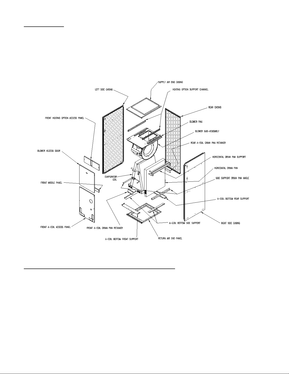
The construction of the air handler permits easy knockdown and reassembly. See Figure A & B.
Figure A.
FOLLOW THESE STEPS FOR KNOCKDOWN OF AH2436:
1. Start with unit setting in a vertical position (Figure A).
2. Remove blower access door.
3. Remove screws from front a-coil access panel, front heating option access panel, front middle panel
and supply air end casing.
4. Remove the front A-coil drain pan retainer and the horizontal drain pan support shipping screw(s)
from the right side casing.
5. Remove the evaporator a-coil assembly.
6. Remove the side support drain pan angles and A-coil bottom front and rear supports.
7. Disconnect power leads and unplug circulation pump connector from the blower control board.
8. Remove the screws that secure the blower assembly to the blower pan and pull blower sub-assembly
out the front of the unit.
Page 5
3
9. Remove screws that secure the blower pan to the side & rear casings.
10. Push the front edges of the side casings slightly apart and remove the blower pan.
11. Remove screws from the return air end panel and side & rear casings.
12. Remove side & rear casings from the return air end panel.
REASSEMBLY OF AH2436
To reassemble the air handler, reverse steps above starting with number 12.
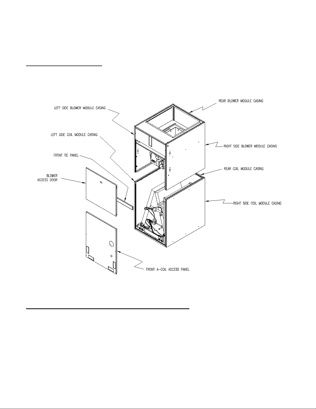
Figure B.
FOLLOW THESE STEPS FOR KNOCKDOWN OF AH4260
1. Start with unit setting in a vertical position (Figure B).
2. Remove the blower access door and front A-coil access panel.
3. Remove front tie panel (four screws).
4. Remove four screws between left/right side blower module casings and left/right side coil module
casings.
5. Remove two screws between rear blower module casing and rear coil module casing.
6. Top blower section is now disengaged from bottom coil section. Lift top off of bottom section.
7. If the Air Handler needs to be completely knocked down, follow steps in procedure for the
knockdown of the AH2436.
Page 6

4
REASSEMBLY OF AH4260
To reassemble the air handler, reverse steps above starting with number 7.
SETTING UP THE A-COIL FOR AIR CONDITIONING
The AH2436 & AH4260 come with the A-coil pre-installed for vertical and left to right horizontal airflow. The A-coil can also be re-positioned for counterflow operation.
IMPORTANT: When air handler is installed in attic above a finished ceiling, it is recommended that a
safety overflow pan with its own separate drain be installed under the entire unit.
For a right to left horizontal air flow the following steps 1-7 must be followed.
Otherwise skip to step 8.
Reversing the horizontal orientation
1. Remove the front a-coil access panel of the air handler.
2. Remove the front a-coil drain pan retainer.
3. Remove the horizontal drain pan support shipping screw(s) from the right side casing.
4. Remove the A-coil assembly and slip the horizontal drain pan assembly off of the right side of the
A-coil.
5. Slip the horizontal drain pan assembly onto the left side of the A-coil.
6. Re-install the A-coil assembly into the air handler. The A-coil drain pan should slide under the rear
retention clip. The horizontal drain pan assembly should rest against the left side casing insulation
and the side support angle.
7. Re-install the front a-coil drain pan retainer in front of the a-coil drain pan.
For all orientations
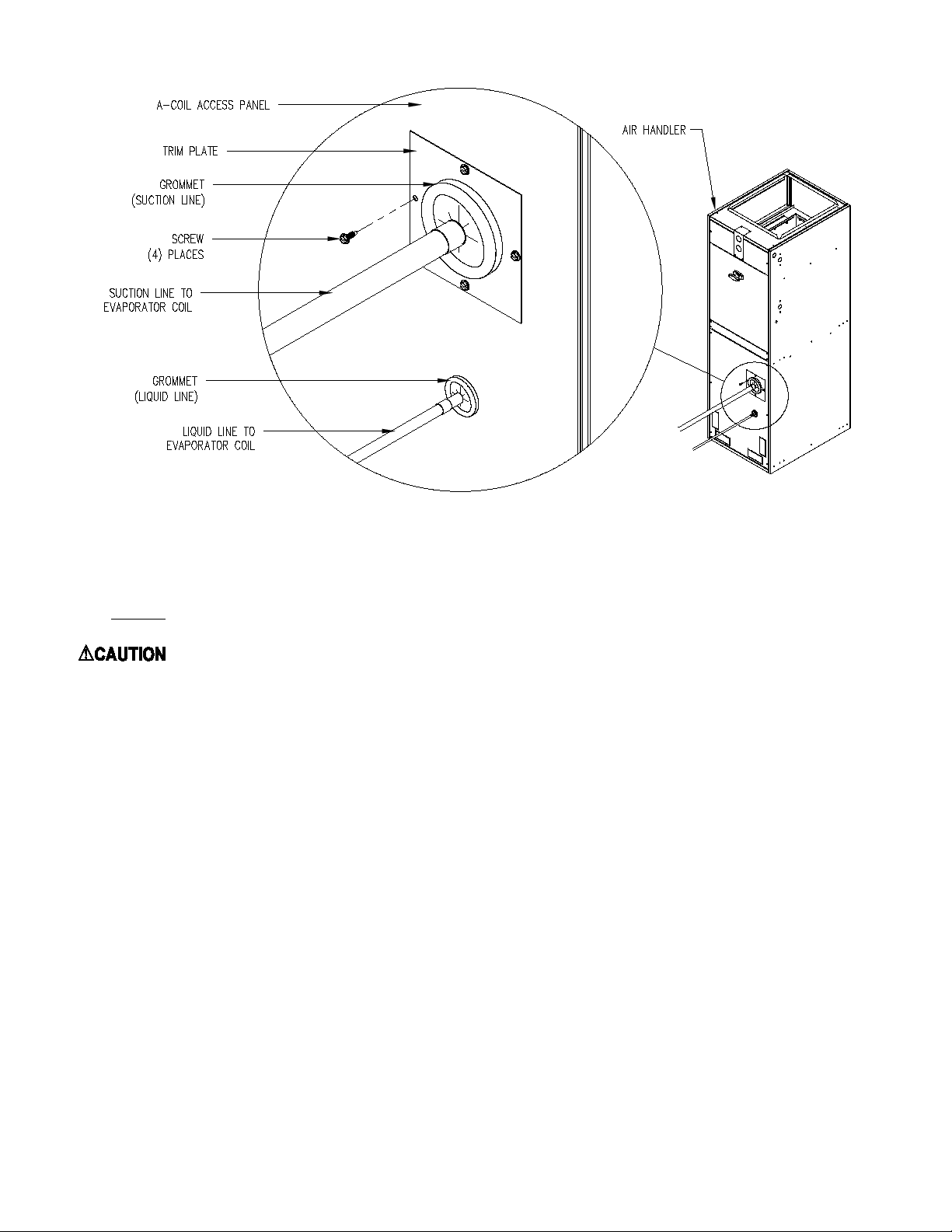
8. Cut open the appropriate drain pan drain access hole in the front A-coil access panel.
9. Slip the Suction line grommet panel over the suction line up to the access panel surface.
Page 7
5
Figure C
11. Make appropriate liquid and suction line connections to coil and braze connections.
NOTE: A wet rag makes an excellent heat sink for tubing and grommets.
: If drilling or screwing into panel of plate is necessary, make certain drill does not penetrate
into any part of evaporator coil or hot water coil to avoid personal injury and/or property damage.
13. Position grommet panel on bottom door surface and secure in place with screws. Refer to Figure C.
14. Make appropriate condensate drain connections and seal the access opening.
Page 8
6
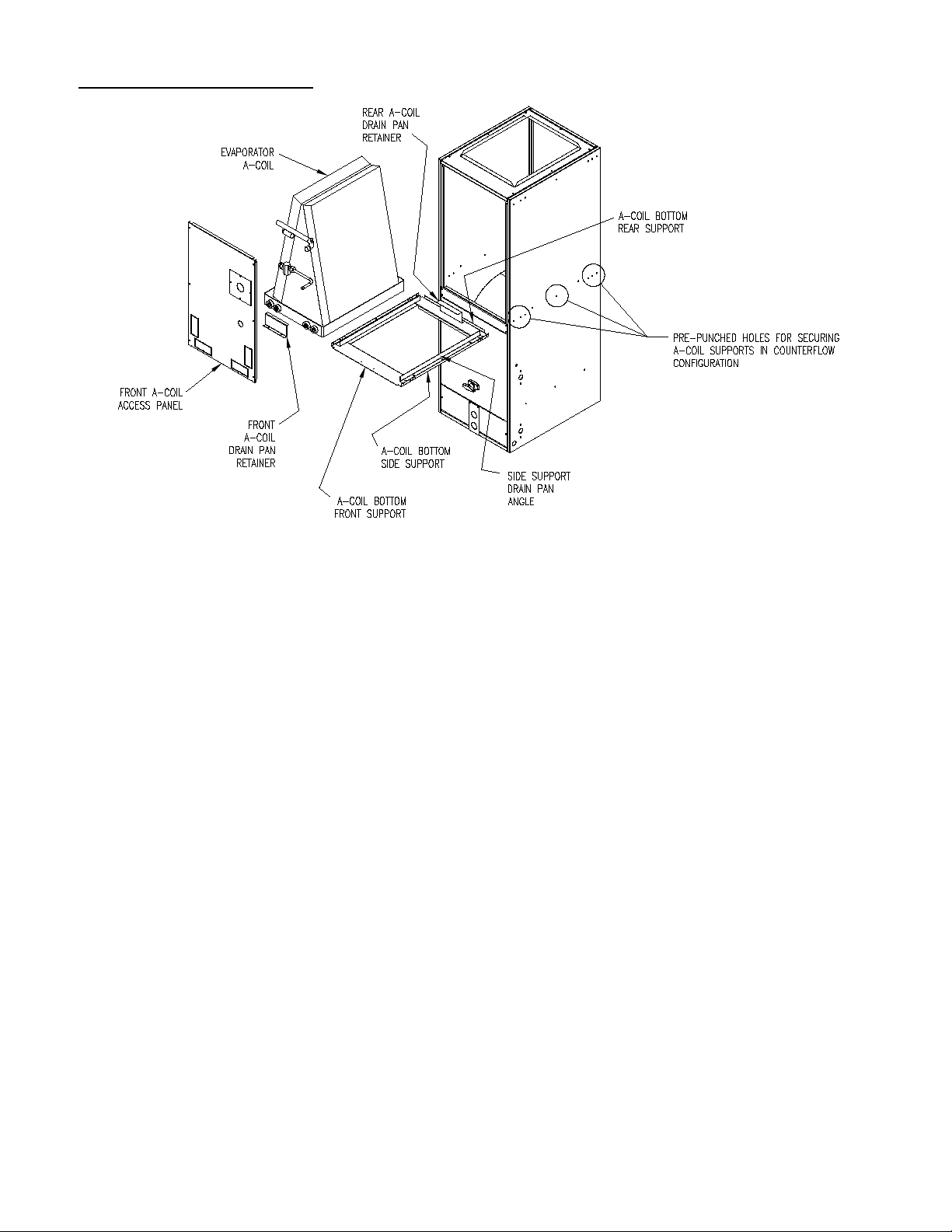
For counterflow orientations:
Figure D
To convert AH2436 to counterflow:
1. Remove front A-coil access panel
2. Remove front a-coil drain pan retainer and the horizontal drain pan support shipping screws from
the right side casing.
3. Remove the A-coil assembly. Slide the horizontal drain pan assembly off of the right side of the
A-coil and discard.
4. Remove A-coil bottom front, side, rear supports, side support drain pan angles and rear a-coil
drain pan retainer.
5. Turn air handler over.
6. Re-install supports, angles and retainer removed in step 4 in the counterflow configuration using
pre punched holes located in the center of the casings.
7. Re-install A-coil and front a-coil drain pan retainer.
8. Re-install front A-coil access panel.
Page 9
7
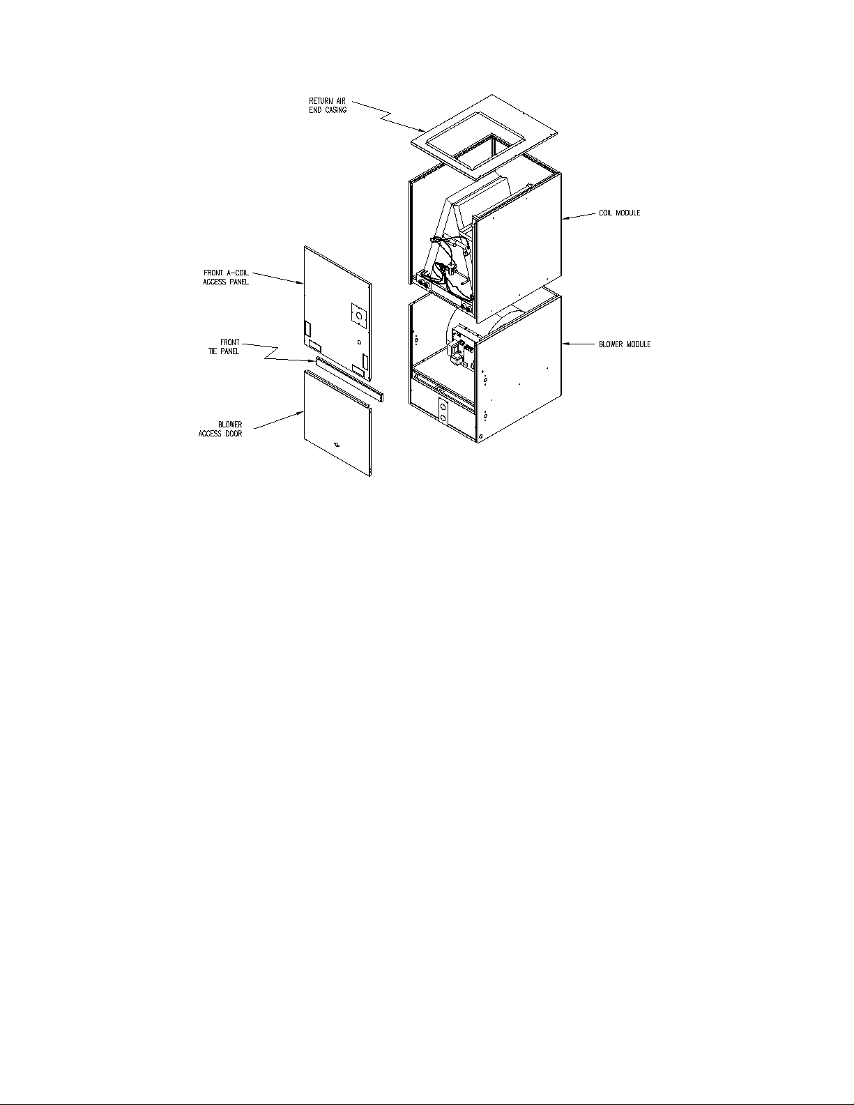
Figure E
To convert AH4260 to counterflow:
1. Remove the blower access door and front a-coil access panel.
2. Remove front tie panel (four screws).
3. Remove four screws between left/right side blower module casings and left/right side coil module
casings.
4. Remove two screws between rear blower module casing and rear coil module casing.
5. Top blower section is now disengaged from bottom coil section.
6. Lift blower module off of coil module.
7. Turn blower module over.
8. Remove return air end casing from coil module.
9. Place coil module on top of inverted blower module.
10. Re-install return air end casing on top of coil module and secure with screws.
11. Re-install all screws which secure blower module to coil module.
12. Re-install front tie panel.
13. Re-install blower access door and front a-coil access panel.
Page 10
8
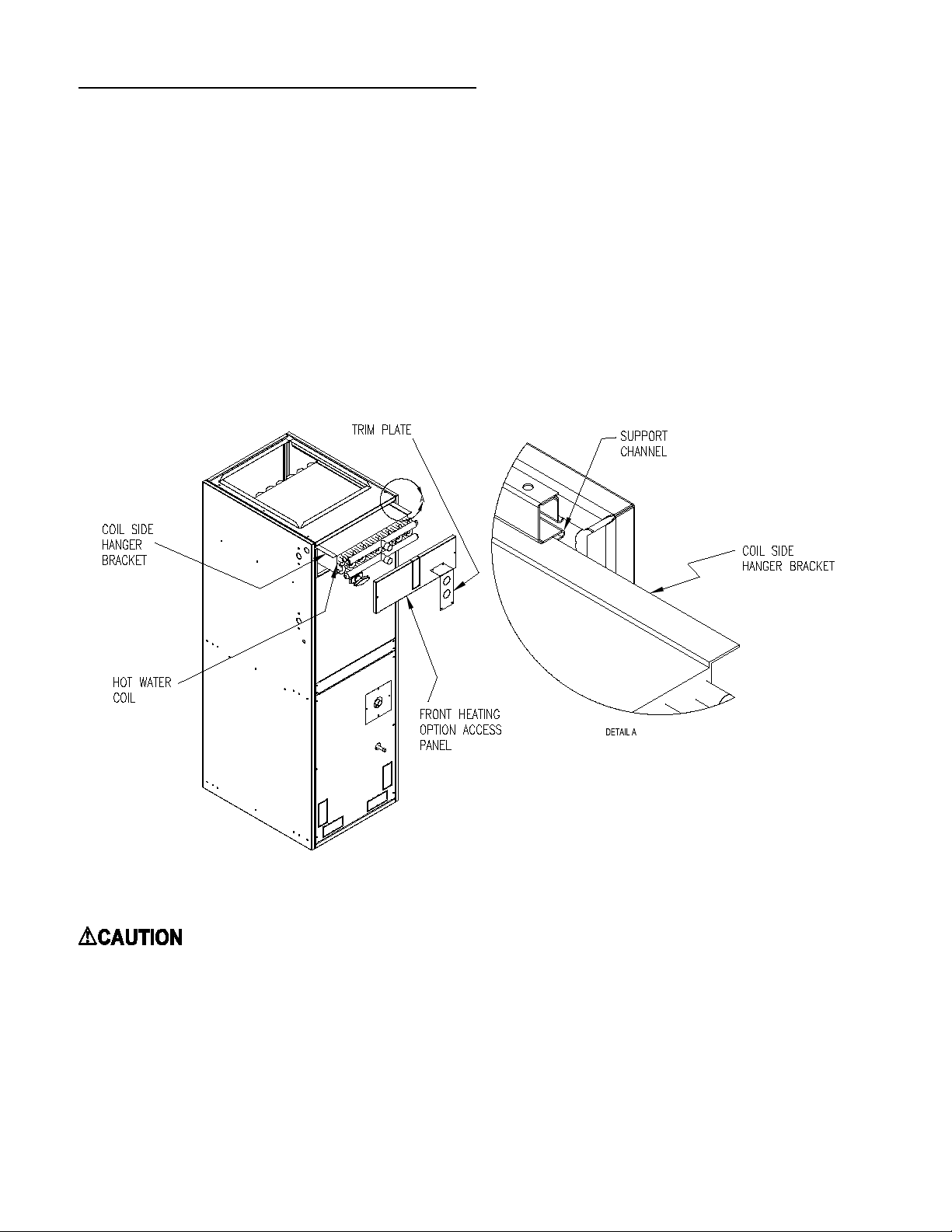
INSTALLATION OF THE HOT WATER COIL:
1. Remove top door of air handler.
2. Slide hot water coil's side hanger brackets into coil channel (retaining channel) in the air handler. See
Figure F.
3. Push coil into unit until the coil is stopped by the back casing.
4. Cut out appropriate holes in insulation, realign top door and secure into place.
5. Make appropriate hydronic connections to inlet (blower side) and outlet (duct side) of coil and braze
into place.
6. Seal connections through panel with duct sealer or equivalent.
Figure F
: If drilling or screwing into panel or plate is necessary, make certain drill does not penetrate
into any part of evaporator coil or hot water coil. Personal injury and/or property damage may result.
Page 11

9
Figure G
NOTE: Drain lines must be pitched no less than 1/4" per foot away from the air handler.
BLOWER AIR ADJUSTMENT
The ECM blower control must be set in order to establish p rop er a ir movement. Use th e f o ll ow i n g s tep s to do this:
1. Identify to tonnage of the condensing unit that will be
used.
2. If Hydronic heat is to be used, identify your BTU heat
requirements, preferred supply air temperature, water
temperature and water flow through the coil in gallons per
minute.
3. Locate the blower control board mounted to the front of
the blower assembly.
4. Locate the red switch block labeled SW1 for adjusting the
Heating and Cooling blower speed.
5. Locate SW2, just below SW1, for adjusting Blower
delays.
Figure H
Page 12

10
Table C1 COOLING SWITCH SETTINGS
AH2436A/BE1 COOL
Settings (SW1)
AH4260A/BE1 COOL
Settings (SW1)
4 5 6 4 5 6 2
800
OFF
OFF
OFF
2-1/2
1000
ON
OFF
OFF
3 1200
OFF
ON
OFF
OFF
ON
OFF
3-1/2
1400
ON
ON
OFF
4
1600 OFF
OFF
ON
1800
ON
OFF
ON
2000
OFF
ON
ON
2200
ON
ON
ON
Shaded cells represent the factory settings
BLOWER COOLING SPEEDS Refer Table C1 for setting switches 4, 5 & 6 for the A/C sizing.
A/C
TONS
CFM
5
BLOWER HEATING SPEEDS WITH HYDRONIC COIL
In the next two pages:
1. Locate the page that refers to the Air Handler to be set up.
2. Find the line(s) on the chart that best represents the water temperature and gallons per minute available.
3. Find the point along the curve that best fits the BTU and Supply Air temperature desired.
4. Read the letter associated with that point and use it to find the switch settings in the table below the chart.
(The table below the switch settings represent the actual numbers represented by the chart.)
Page 13

11
AH2436*E1 Temperature & Heat Values at 140, 160 & 1800F and
3,4,5,6 & 7 gallons per minute at selected speeds
95
105
115
125
135
145
155
25 35 45 55 65 75 85
Heating Capacity (KBTU/H)
Supply Air w/70º Return (ºF)
7gpm:180
6pgm
5gpm
4gpm
3gpm
7gpm:160
6gpm
5gpm
4gpm
3gpm
7gpm:140
6gpm
5gpm
4gpm
3gpm
1400F
Water
1800F
1600F Water
A
B
C
D
E
F
G
H
Motor Speed (A,B,C etc.)
SPEED CFM
1 2 3
A
689 OFF OFF OFF
B
754 ON OFF OFF
C 819
OFF ON OFF
D 897
ON ON OFF
E 975 OFF OFF ON
F 1066 ON
OFF ON
G
1170
OFF
ON ON
H
1300 ON ON ON
Water
Temperature
Flow
Tubeside
PD
CFM 689 (A) 754 (B)
819 (C) 897 (D) 975 (E) 1066 (F)
1170 (G) 1300 (H)
Supply Air (ºF) 151º 148º 145º 142º
139º 136º 133º 129º
Heat (Kbtu/H)
61517 64858 67946 71362
74504 77871 81378 85332
Supply Air (ºF) 149º 146º 143º
140º 137º 134º 131º 127º
Heat (Kbtu/H) 60283 63437 66346
69553 72493 75631 78888 82545
Supply Air (ºF)
147º 144º 141º 138º 135º 132º 128º
125º
Heat (Kbtu/H) 58593 61512 64191 67131
69813 72663 75606 78893
Supply Air (ºF) 144º 140º 137º 134º 131º 128º
125º 121º
Heat (Kbtu/H) 56163 58766 61139 63727
66073 68549 71090 73907
Supply Air (ºF)
139º 135º 132º 129º 126º 123º 120º 116º
Heat (Kbtu/H) 52393 54554 56507
58615 60509 62490 64505 66717
Supply Air (ºF) 136º 133º 131º 128º 126º 124º
121º 118º
Heat (Kbtu/H)
50092 52795 55294 58057 60597 63317 66151 69343
Supply Air (ºF) 134º 132º 129º 127º
124º 122º 119º 116º
Heat (Kbtu/H) 49061
51611 53962 56554 58928 61461 64090 67039
Supply Air (ºF) 132º 130º 127º 125º 122º 120º
117º 114º
Heat (Kbtu/H)
47654 50011 52174 54547 56711 59009 61382 64031
Supply Air (ºF) 130º 127º 125º 122º
120º 117º 114º 111º
Heat (Kbtu/H) 45639 47738 49652 51738 53629 55624 57670 59939
Supply Air (ºF) 126º 123º 120º 118º
115º 113º 110º 107º
Heat (Kbtu/H)
42530 44272 45845 47544 49069 50664 52286 54068
Supply Air (ºF) 121º 119º 117º 115º
113º 111º 109º 107º
Heat (Kbtu/H) 38730 40806 42723 44842 46788 48872 51041 53484
Supply Air (ºF) 120º
118º 116º 114º 112º 110º 108º 106º
Heat (Kbtu/H) 37900 39865 41666 43651 45468 47406 49417 51672
Supply Air (ºF) 118º 116º
114º 112º 110º 108º 106º 104º
Heat (Kbtu/H) 36792 38597 40252 42067 43721 45478 47290 49313
Supply Air (ºF) 116º
114º 112º 110º 108º 106º 104º 102º
Heat (Kbtu/H) 35200 36806 38268 39862 41305 42828 44390 46121
Supply Air (ºF) 113º 111º 109º 107º
105º 103º 101º 99º
Heat (Kbtu/H) 32760 34090 35291 36588 37751 38968 40206 41565
1.16
1.94
1.13
5.67
4.25
4.15
2.95
3.02
1.99
2.88
1.89
1.11
5.54
Heat Settings (SW1)
180º F
7 gpm
6 gpm
5 gpm
4 gpm
3 gpm
5.42
4.05
160º F
7 gpm
6 gpm
5 gpm
4 gpm
3 gpm
140º F
7 gpm
6 gpm
5 gpm
4 gpm
3 gpm
HYDRONIC COIL MODEL HC1-B
Page 14

12
AH4260*E1 Temperature & Heat Values at 140, 160 & 180°F
and 7,8,9 & 10 gallons per minute at selected speeds
100
110
120
130
140
150
40 60 80 100 120
Heating Capacity (KBTU/H)
Supply Air w/ 70° Return (°F)
10gpm:180
9gpm
8gpm
7gpm
10gpm:160
9gpm
8gpm
7gpm
10gpm:140
9gpm
8gpm
7gpm
1800 F Water
1600 F Water
1400 F
Water
A
B
C
D
E
F
G
H
Motor Speed (A,B,C etc.)
Heat Settings (SW1)
SPEED CFM 1 2 3
A 1007 OFF OFF OFF
B 1102 ON OFF
OFF
C 1197 OFF ON OFF
D 1311 ON ON OFF
E 1425 OFF OFF ON
F
1558 ON OFF ON
G 1710 OFF ON ON
H
1900 ON
ON ON
Supply Air (oF)
148 146 144 141 139 136 133 130
Heat (Kbtu/H) 86 91 96 101 106 112 117 124
Supply Air (oF)
147 145 142 140 137 135 132 129
Heat (Kbtu/H) 85 90
94 99 104 109 115 121
Supply Air (oF)
146 144 141 138 136 133 130 127
Heat (Kbtu/H) 83 88 92 97 102 107 112 118
Supply Air (
o
F)
145
142 139 137 134 131 129 125
Heat (Kbtu/H) 82 86 90 95 99 104
109 114
Supply Air (oF)
134 132 130 128 126 124
121 119
Heat (Kbtu/H)
70 74 78 82 86 91 95 101
Supply Air (oF)
133 131 129 127 125 123 120 118
Heat (Kbtu/H) 69 73 77 81 85 89 94 99
Supply Air (oF)
132 130 128 126 124 121 119 117
Heat (Kbtu/H) 68 72 75 79 83 87 91 96
Supply Air (oF)
131 129 127 124 122 120 118 115
Heat (Kbtu/H) 66 70 73 77 81 84 88 93
Supply Air (oF)
119 118 116 115 113 111 110 108
Heat (Kbtu/H) 54 57 60 64 67 70 74 78
Supply Air (oF)
119 117 116 114 112 111 109 107
Heat (Kbtu/H) 53 56 59 62 66 69 72 76
Supply Air (oF)
118 116 115 113 111 110 108 106
Heat (Kbtu/H) 52 55 58 61 64 67 70 74
Supply Air (oF)
117 115 114 112 110 109 107 105
Heat (Kbtu/H) 51 54 57 60 62 65 68 72
Inlet Water
Temperature
Flow
Tubeside
PD
CFM
1007 (A)
1102 (B)
1197 ('C)
1311 (D)
1425 (E)
1558 (F)
1710 (G)
1900 (H)
180oF H2O
10 gpm
1.88
9 gpm
1.54
8 gpm
1.23
7 gpm
0.95
160OF H2O
10 gpm
1.92
9 gpm
1.57
8 gpm
1.25
7 gpm
0.97
140oF H2O
10 gpm
1.95
9 gpm
1.6
8 gpm
1.27
7 gpm
0.99
HYDRONIC COIL MODEL HC2-A
Page 15

13
Table D1: Delays before blower cycles “ON or “OFF”
SW2 Positions
“ON” Delay
SW2 Positions
“OFF” Delay
1 2 (Seconds)
3 4 (Minutes)
OFF
OFF
30
OFF
OFF
2
ON
OFF
60
ON
OFF
4
OFF
ON
120
OFF
ON
6
ON
ON
480
ON
ON
8
BLOWER TIME DELAY
In cases where the yellow wires are used to start and stop the hydronic pump, SW2 may be used to delay
when the blower is cycled on or off to increase comfort and efficiency.
Use Table D1 to set the switches appropriately
DUCT SYSTEM
The duct system and load sizing calculation should follow the design standards of Air Conditioning
Contractors of America (ACC A) - manuals D & J - or t he Am eri can S oci et y of Heating, Refri geratio n and
Air Conditioning Engineers, Inc. (ASHRAE) Latest Edition Fundamentals Volume.
To aid you in evaluating existing duct systems quickly, review the chart on Page 14 which shows the CFM
capacity for square inch areas, based on .10" wc static pressure (SP) loss on the supply systems.
Each of the system's components (trunk lines, take-offs, runs and register and grill-free areas) must be
properly sized and matched together to ensure you are obtaining the air handling capacity of the duct
system. A 12x8 duct with a 400 CFM capacity, for example, MAY NOT flow 400 CFM if the register(s)
to which it connects can only flow a total of 200 CFM.
The air handling capacity MUST BE EQUAL TO the supply system at a minimum when sizing the
return air duct system. It is recommended to follow design parameters set down by ACCA or ASHRAE on
the return air duct systems.
Page 16

14
DUCT SIZES FOR HOMES
Velocity Approximately 800 Feet Per Minute
THE INDOOR EVAPORATOR COIL
1. EVAPORATO R COIL is a finned coil through which air in the home is circulated. Heat from the air
is transferred to the liquid refrigerant inside the evaporator coil. The coils for use in AH air handlers are in
an A-shaped configuration (A Models).
2. CONDENSATE DRAIN PAN is attached to the bottom of the evaporator coil to collect water
condensed out of the air. Two drain fittings are provided for connection to a convenient drain point.
3. HORIZONTAL CONDENSATE DRAIN PAN is attached to the right side of the first one for
horizontal left to right air flow. It may relocated to the left side as well. A drain fitting is provided for
connection to a convenient drain point.
TUBING LINE SETS
1. SUCTION LINE is an insulated large copper tube connecting the outlet of the A/C evaporator to the
suction inlet of the A/C CONDENSER.
Page 17

15
Tube Diameter for Total Line Length
0-50’
50-75’
75-100’
MODEL
Suction
Liquid
Suction
Liquid
Suction
Liquid
HP14241A1, HP14301A1,
AC14241E2, AC14301E2
HP14361A1, HP14421A1,
HP1448xA1, HP1460xA1
AC14361E2, AC14421E2,
2. LIQUID LINE is a single small tube connecting the outlet of the A/C condenser to the expansion valve
inlet on the A/C evaporator coil.
TUBING SIZE REFERENCE CHART
3/4” 3/8” 7/8” 3/8” 1-1/8” 1/2”
7/8” 3/8” 1-1/8” 1/2” 1-1/8” 5/8”
AC1448xE2, AC1460xE 2
7/8” 1/2” 1-1/8” 1/2” 1-1/8” 5/8”
NOTES:
For line lengths over 25’ adjust charge accordingly per foot of variation from chart.
.65 oz. per foot for 3/8” and 3/4” line set
.674 oz. per foot for 3/8” and 7/8” line set
.694 oz. per foot for 1/2” and 7/8” line set
.72 oz. per foot for 1/2” and 1” line set
.76 oz. per foot for 5/8” and 1-1/8” line set
These charges are to be used in conjunction with a liquid sub-cooling measurement for best performance.
Page 18

16
TUBING INSTALLATION
The compressor oil is constantly pumped through the refrigerant lines in normal operation of an air
conditioning system. To ensure proper lubrication of the compressor by avoiding oil accumulation at
undesirable points in the system, follow the guidelines listed below:
1. No traps in the suction line are necessary if the outdoor condensing unit is level with the indoor
evaporator coil or the indoor evaporator coil is 4 feet or less lower then the outdoor condensing unit.
Any horizontal runs of suction line should have minimum 1/2" pitch for every 10 feet of line towards
the outdoor condensing unit. See Figure I.
Figure I.
2. A trap is necessary in the suction line at the indoor evaporator coil if the indoor evaporator coil is
more than 4 feet below the outdoor condensing unit.
Figure J.
Page 19

17
NOTE: Multiple suction line traps are recommended for longer or multiple suction lines. See Figure J.
An inverted trap should be installed on the horizontal suction line near the evaporator coil to prevent
liquid flood back to the compressor (See Figure K.) if the indoor evaporator coil is located 10’ or more
above the condensing unit.
Figure K.
A gradual loop in the tubing can be constructed to take up the excess tubing if you find that too much
tubing has been brought onto a job. Such a loop MUST be kept in a horizontal (flat) plane to avoid
trapping the oil.
Refrigerant lines should be inserted into a suitable conduit or raceway when the lines are to be buried
between the building and the outdoor condensing unit. The lines must be provided with sufficient
protection and support to prevent damage when installed above ground.
When making "on the job" tubing, a solder of 95% tin, 5% antimony or any of the silver solders such as
SilFos, Phos-Copper, Easy-Flo 35 or 45, should be used. No attempt will be made here to instruct proper
soldering or brazing technique but it is necessary that the installer be properly instructed in accordance
with good existing practices.
All joints and fittings must be properly leak tested as per EPA guidelines after “on the job” tubing has
been made up. The line set and the evaporator coil must be evacuated to 29.96” Hg (1000 microns) or
lower when all joints and fittings are leak free. The service valves on the condenser may then be opened to
release the refrigerant to th e system. Verify proper system performance. See condensing unit manual for
additional performance data.
Page 20

18
HOW TO MEASURE LIQUID SUB-COOLING
(NOTE: A good electronic thermometer and accurate liquid pressure gauge with a check valve in the
Schraeder fitting are necessary).
: Failure to use a liquid side hose fitting with a built in check valve may result in personal
injury and significant refrigerant loss.
Sub-cooling is measured by taking a temperature and pressure reading. See Figure L. The pressure reading
is gauged at the pressure port located on the liquid service valve. The temperature reading is taken at the
liquid line at the 3:00 o'clock or 9:00 o'clock position with the liquid line as the center of the clock.
Figure L.
Make sure the tube where the temperature is measured is not in direct sunlight.
Read the temperature at the liquid line.
Read the liquid pressure.
Then convert pressure into temperature.
Next, subtract the measured tube temperature from the converted suction temperature.
The end result is the liquid sub-cooling.
EXAMPLE:
Measured Temp = 95oF
Measured Pressure = 211PSI which equates to a 105oF saturation temperature.
(Listed temperature for measured pressure according to R-22 temperature scale on manifold gauge or R22 section of pressure temperature chart)
The difference equals the degrees superheat = 10oF
Page 21

19
A liquid sub-cooling of about 10oF leaving the condenser is good over a wide range of operating
conditions for a system with a TXV in the evaporator like the AH2436A/BE1 & AH4260A/BE1.
MEASURING TEMPERATURE DROP ACROSS THE “A” COIL:
The temperature drop across the coil should be around 18oF to 23oF difference between inlet an d outlet
air. This should be measured as close to the air handler as possible, to eliminate duct losses.
ELECTRICAL
All wiring must conform to the provisions of local codes or in the absence of local codes with the
provisions of the National Electrical Code, ANSI/NFPA No. 70-Latest Edition and this instruction
manual. Equivalent type wire must be used if any of the original wire supplied with the unit needs to be
replaced.
NOTE: Condensing unit is not included in above amp rating.
Page 22

20
Max fuse size for AH2436BE1 w\ EH104A 30A EH108A 45A
Max fuse size for AH4260BE1 w\ EH208A 50A EH212A 70A EH216A 85A
The following points must be checked by the installer and/or electrician before the air conditioning system
is started:
1. Check every electrical connecti on of "PUSH-ON " or "SCR EW-ON" terminals to ensure it is on tightly
on its proper post.
2. Review wiring diagram for proper routing.
Page 23

21
Page 24

22
UA ADAPTER CABINET
The UA adapter cabinet is designed to be used in conjunction with the AH AIR HANDLER to allow a
free standing (vertical discharge) installation. The UA cabinet is shipped completely assembled and ready
for installation.
The return air opening can face either left or right by exchanging the front filter door and rear filter blockoff assemblies.
The AH AIR HANDLER is then placed on the UA adapter cabinet, inlet side down.
The UA cabinet is equipped with a permanent washable air filter.
AH AIR HANDLER RECOMMENDED SUSPENSION PROCEDURE
The detail below is the proper and safest way to suspend the AH. These components should be easily
found at your local hardware store.
FIG M
Page 25

23
SYMPTOM
CAUSE/PROCEDURE
Motor rocks slightly when starting
• This is normal start-up for ECM
Motor won’t start
• Check power at motor
• Run Moisture Check
• Motor rocks, but won’t start
• Check for loose or compliant motor mount
• Perform motor/control replacement check
Motor oscilla tes up & down while being tested off
of blower
• It is normal for motor to oscillate with no load on
shaft.
Motor starts, but runs erratically
• Perform Moisture Check
• “Hunts” or “puffs” at high CFM (speed)
• Does removing panel or filter reduce “puffing”?
Reduce max airflow
• Stays at low CFM despite system call for cool or
• Check low voltage (T’stat) wires and connections
• Perform motor/control replacement check
ECM TROUBLE SHOOTING
DIAGNOSTC FEATURES
The control board is equipped with 4 green Input Status LEDs and 1 red Board Status LED. These are
intended to provide a quick view into furnace performance without requiring a voltmeter.
The green Input Status LEDs are driven by the “Y”, “W”, “G”, and “DEHUM” inputs and are located
directly below those inputs. They will light to indicate the presence of these signals.
The red Board Status LED has two functions:
It will light when the board recognizes a valid input signal and will stay lit until all valid signals are
removed. This is intended to show that the board is functioning and able to respond to input signals.
B. GENERAL GUIDELINES TO TROUBLESHOOTING GE ECM – DRIVEN SYSTEMS
: Disconnect power from unit before removing or replacing connectors, or servicing
motor. Wait at least 5 minutes after disconnecting power before opening motor.
• No movement
• Varies up and down or intermittent
• Check low voltage (24 VAC R to C) at motor
• Check low voltage connections (G,PWM,W,R,C,)
at motor
• Check for unseated pins in connectors on motor
harness
• Test with a temporary jumper between R – G
• Check motor for tight shaft
• Perform motor/control replacement check
• Make sure blower wheel is tight on shaft
• Check line voltage for variatio n or “sag”
• Check low voltage connections (G,PWM,W,R,C,)
at motor, unseated pins in motor harness
connectors
• Check “Bk” for erratic CFM command (in
variable speed applications)
• Check-out system controls – T’stat?
heat CFM
Reduce restriction
• Verify fan is not in delay mode – wait until delay
complete
• “R” missing/not connected at motor
Page 26

24
• Stays at high CFM
• “R” missing/not connected at motor
• Perform motor/control replacement check
• Blower won’t shut off
• Current leakage fr om controls into G,Y or W?
Check for Triac switched t’stat or solid state relay
Excessive noise
• Determine if it’s air noise, cabinet, duct or motor
noise – interview customer, if necessary
• Noisy blower or cabinet
• Check for loose blower housing, panels, etc.
Check for cabinet/duct deformation
• “Hunts” or “puffs” at high CFM (speed)
• Does removing panel or filter reduce “puffing”?
Reduce max airflow
Evidence of Moisture
• Motor failure or malfunction has occurred and
moisture is present
• Replace motor and perform Moisture Check
• Evidence of moisture present inside air mover
• Perform Moisture Check
DO
DON’T
• Check-out motor, controls, wiring and
connections thoroughly before replacing motor
• Automatically assume the motor is bad.
• Orient connectors down so water can’t get in
Install “drip loops”
• Locate connectors above 7 and 4 o’clock
positions
• Use authorized motor and control model #’s for
replacement
• Replace one motor or control model # with
another (unless an authorized replacement)
• Keep static pressure to a minimum:
replacement
• Use high pressure drop filters – some have ½”
• Size the equipment wisely
• Oversize system then compensate with low
airflow
• Check orientation before inserting motor
connectors
• Plug in power connector backwards
• Force plugs
• Is fan in delay mode? – wait until delay time
complete
• High static creating high blower speed?
Check for air whistli ng t hru
seams in ducts, cabinets or panels
Reduce restriction
Recommend high efficiency, low static
filters
Recommend keeping filters clean
Design ductwork for min sta tic, max
comfort
Look for and recommend ductwork
improvement, where necessary, in
Moisture Check
• Connectors are orientated “down” (or as recommended by equipment manufacturer)
• Arrange harnesses with “drip loop” under motor
• Is condensate drain plugged?
• Check for low airflow (too much latent capacity)
• Check for undercharged condition
• Check and plug leaks in return ducts, cabinet
H2O drop!
• Use restricted returns
Page 27

25
Comfort Check
• Check proper airflow settings
• Low static pressure for lowest noise
• Set low continuous-fan CFM
• T’stat in bad location?
120V or 240V
120V or 240V
Figure N: ECM PIN CONNECTORS
Troubleshooting table above and Figure N adapted from GE Industrial Systems publication GED-7161C,
“Troubleshooting GE ECM – Driven Systems”.
Page 28

26
CONFIRM IF EITHER BLOWER
WHEEL IS RUBBING AGAINST
HOUSING OR MOTOR SHAFT
IS SPINNING FREELY, REPAIR
OR REPLACE AS NECESSARY.
DOES BLOWER SPIN FREELY
?
IS THERE 120V or 240V
SUPPLIED TO MOTOR?
CHECK 120V or 240V SUPPLY,
CONNECTION FUSES,
SERVICE SWITCH AND
DOOR SWITCH.
CHECK HARNESS
CONNECTIONS
AND WIRE.
NO
YES
YES
YES
YES
NO
NO
NO
NO
NO
YES
YES
DISCONNECT 16 PIN
HARNESS FROM
MOTOR. IS THERE 12VDC
ACROSS PIN12 & PIN1
AND PIN12 & PIN3
AT THE HARNESS PLUG?
CHECK CONNECTION ON HARNESS AND MOTOR,
RECONNECT HARNESS TO MOTOR, IF
CONNECTIONS ARE GOOD AND MOTOR STILL
DOES NOT RUN REPLACE MOTOR.
THIS GUIDE SHOULD BE USED IN THE CASE OF A STO P P E D O R MA NFUNCTIONED ECM
BLOWER MOTOR. THE FOLLOWING SHOULD HELP ESTABLISH THE TYPE OF
MALFUNCTION OR DEVIATION FROM THE NORMAL BLOWER OPERATION.
TO USE THIS DIAGRAM, YOU JUST NEED TO FOLLOW THE INSTRUCTIONS IN THE BOXES.
CHECK 24VAC
TO INTEGRATED CONTROL.
IS THERE 24VAC
ACROSS R &
B/C ON THE
INTEGRATED
CONTROL?
REPLACE
INTEGRATED
CONTROL.
TURN THERMOSTAT MANUAL FAN
SWITCH ON (IF AVAILABLE) OR JUMPER
BETWEEN R & G ON INTEGRATED CONTROL.
IS THERE VOLTAGE GREATER THAN
12VDC BETWEEN PIN15 & PIN1?
CHECK CONNECTIONS AND WIRES
AT INTEGRATED CONTROL, IF OK
REPLACE INTEGRATED CONTROL.
DISCONNECT 16PIN
HARNESS FROM
INTEGRATED CONTROL.
IS THERE 12VDC ACROSS
PIN 6 & PIN 1
AT THE CONROL?
TROUBLESHOOTING CHARTS
Page 29

27
BLOWER Off-
Delay Active?
Sequence of Operation
BURNER On
1. A/C Off
BLOWER
= LOW
BLOWER = COOL
COOL
Y
On-Delay
Yes
Yes
Yes
Yes
No
No
No
No
DEHUM
BLOWER = LOW
1. BLOWER Of f (No Delay)
1. HEAT mode On
1. COOL mode On
1. FAN mode On
G Active?
Y Active?
LIMIT
FAN Mode
G
W Act ive?
1. HEAT mode On
Yes
Yes
Yes
Yes
Yes
Yes
No
No
No
No
No
No
Yes
No
1.BURNER Off
HEAT
W
Active?
LIMIT
On-Delay
Yes
Yes
Yes
Yes
No
N
No
No
Mode On?
Mode On?
On?
2. HEAT mode Off
3. BLOWER Of f -Delay S tarted
4. Status LED Off
Active?
2. COOL mode Off
3.BLOWER Of f -Delay S tarted
4. Status LED Off
Active?
Ended?
Ended?
Active?
Active?
Active?
2. Status LED Off
2. BLOWER = HEAT
3. Status LED Flashes
2. Blower On-Delay Started
3. Burner On
4. Status LED On (conti nuous )
2. Blower On-Delay Started
3. Condenser On
4. Status LED On (conti nuous )
2. BLOWER = LOW
3. Status LED On (conti nuous )
Page 30

28
Sequence of Operation Glossary
Inputs:
W- Switched 24vac indicating a Heat call from the thermostat.
Y - Switched 24vac indicating a Cool call from the thermostat.
G - Switched 24vac indicating a call for blower operation from the thermostat.
DEHUM - Switched 24vac indicating a call for Dehumidification from a de-humidistat.
BLOWER Speeds:
HEAT - The Heating Blower speed selected by positions 1, 2 & 3 of SW1
(CFM tables on page 11-12)
COOL - The Cooling Blower speed selected by positions 4, 5 & 6 of SW1
(CFM tables on page 10)
LOW - The LOW Blower speed selected by positions 4, 5 & 6 of SW1
(CFM tables on page 10)
ECM – PSC Replacement for AH2436AE1 or AH4260AE1 only
In an emergency situation, a defective ECM motor can be replace with a PSC motor to provide temporary
circulating air flow for heating or cooling. This is done by replacing the ECM motor in the motor
mounting bracket with a PSC motor of similar Horsepower. Wire the common lead (typically white) of
the replacement PSC motor to the neutral (common) terminal on the fan control board (N - 1 through 7).
Connect the high-speed replacement PSC motor lead (typically black) to the EAC terminal on the fan
control board. The EAC contact is energized with 115VAC any time the control board is calling for fan
operation whether in heating or cooling mode. This replacement should be only used in emergency
situations and only until a replacement ECM motor can be obtained and reinstalled.
ECM – PSC Replacement for AH2436BE1 or AH4260BE1 - call Tech Service.
Page 31

29
REPLACEMENT PARTS
Page 32

30
 Loading...