

Page 1
MODULAR
INSTALLATION MANUAL
MAC-225
ECN 5287-MA 121005
NON-VARIABLE SPEED AIR HANDLERS
MODELS: MA
LIST OF SECTIONS
GENERAL . . . . . . . . . . . . . . . . . . . . . . . . . . . . . . . . . . . . . . . . . . . . . . 1
SAFETY . . . . . . . . . . . . . . . . . . . . . . . . . . . . . . . . . . . . . . . . . . . . . . . . 1
UNIT INSTALLATION . . . . . . . . . . . . . . . . . . . . . . . . . . . . . . . . . . . . . 2
ELECTRIC HEATER INSTALLATION . . . . . . . . . . . . . . . . . . . . . . . . 5
LOW VOLTAGE CONTROL CONNECTIONS . . . . . . . . . . . . . . . . . . 6
REQUIRED CONTROL
LIST OF FIGURES
Typical Installation with MC Multi-Position Coils . . . . . . . . . . . . . . . . . 3
Coil and Air Handler Attachment Details . . . . . . . . . . . . . . . . . . . . . . .3
Gasket Location . . . . . . . . . . . . . . . . . . . . . . . . . . . . . . . . . . . . . . . . . .4
Dimensions & Duct Connection Dimensions . . . . . . . . . . . . . . . . . . . . 4
Typical Horizontal Installation . . . . . . . . . . . . . . . . . . . . . . . . . . . . . . . 5
Control Board . . . . . . . . . . . . . . . . . . . . . . . . . . . . . . . . . . . . . . . . . . . . 5
Line Power Connections . . . . . . . . . . . . . . . . . . . . . . . . . . . . . . . . . . .8
LIST OF TABLES
Dimensions . . . . . . . . . . . . . . . . . . . . . . . . . . . . . . . . . . . . . . . . . . . . . 4
Low Voltage Connections . . . . . . . . . . . . . . . . . . . . . . . . . . . . . . . . . . 6
Fault Codes . . . . . . . . . . . . . . . . . . . . . . . . . . . . . . . . . . . . . . . . . . . . .7
Low Fan Control Inputs . . . . . . . . . . . . . . . . . . . . . . . . . . . . . . . . . . . . 7
Blower Delays . . . . . . . . . . . . . . . . . . . . . . . . . . . . . . . . . . . . . . . . . . .7
Heat Relays . . . . . . . . . . . . . . . . . . . . . . . . . . . . . . . . . . . . . . . . . . . . . 7
Physical and Electrical Data . . . . . . . . . . . . . . . . . . . . . . . . . . . . . . . . . 9
Electrical Data - Cooling Only (60 Hz) - 208/230 . . . . . . . . . . . . . . . . .9
Electrical Data - Cooling Only (60 Hz) - 460 . . . . . . . . . . . . . . . . . . . .9
Conversion Table . . . . . . . . . . . . . . . . . . . . . . . . . . . . . . . . . . . . . . . . . 9
Electrical Data - 1 Ø - 208/230-1-60 . . . . . . . . . . . . . . . . . . . . . . . . . 10
Electrical Data - (For Multi-Source Power Supply) -
Copper Wire 1 Ø - 208/230-1-60 . . . . . . . . . . . . . . . . . . . . . . . . . . . . 10
ISO 9001
Certified Quality
Management System
SET-UP . . . . . . . . . . . . . . . . . . . . . . . . . . . . . . . . . . . . . . . . . . . . . . . . 6
LINE POWER CONNECTIONS . . . . . . . . . . . . . . . . . . . . . . . . . . . . . 8
BLOWER SPEED CONNECTIONS . . . . . . . . . . . . . . . . . . . . . . . . . . 8
UNIT DATA . . . . . . . . . . . . . . . . . . . . . . . . . . . . . . . . . . . . . . . . . . . . 9
MAINTENANCE . . . . . . . . . . . . . . . . . . . . . . . . . . . . . . . . . . . . . . . . 15
WIRING DIAGRAM . . . . . . . . . . . . . . . . . . . . . . . . . . . . . . . . . . . . . 16
460V - Line Power Connections . . . . . . . . . . . . . . . . . . . . . . . . . . . . . 8
Blower Speed Connections . . . . . . . . . . . . . . . . . . . . . . . . . . . . . . . . 8
460V - Blower Speed Connections . . . . . . . . . . . . . . . . . . . . . . . . . . . 8
Cooling Models with Electric Heat Wiring . . . . . . . . . . . . . . . . . . . . . 15
Single-Stage Cooling Wiring . . . . . . . . . . . . . . . . . . . . . . . . . . . . . . . 15
Wiring Diagram . . . . . . . . . . . . . . . . . . . . . . . . . . . . . . . . . . . . . . . . . 16
Electrical Data - (For Single Source Power Supply) -
Copper Wire 1 Ø - 208/230-1-60 . . . . . . . . . . . . . . . . . . . . . . . . . . . 11
Electrical Data - 3 Ø - 208/230-3-60 . . . . . . . . . . . . . . . . . . . . . . . . . 11
Electrical Data - (For Multi-Source Power Supply) -
Copper Wire 3 Ø - 208/230-3-60 . . . . . . . . . . . . . . . . . . . . . . . . . . . 12
Electrical Data - (For Single Source Power Supply) -
Copper Wire 3 Ø - 208/230-3-60 . . . . . . . . . . . . . . . . . . . . . . . . . . . 12
Electrical Data - 460-3-60 . . . . . . . . . . . . . . . . . . . . . . . . . . . . . . . . . 12
Electrical Data - (For Single Source Power Supply) -
Copper Wire 3 Ø - 460-3-60 . . . . . . . . . . . . . . . . . . . . . . . . . . . . . . . 12
Air Flow Data - 60 Hz Models (230 & 460 Volt) . . . . . . . . . . . . . . . . 13
Air Flow Data - 60 Hz Models (208 Volt) . . . . . . . . . . . . . . . . . . . . . 14
SECTION I: GENERAL
This modular air handler provides the flexibility for installation in any
upflow, downflow, or horizontal application. These versatile models may
be used for cooling or heat pump operation with or without electric heat.
A BRAND LABEL (available from Distribution) may be applied to the
center of the blower access panel.
The unit can be positioned for bottom return air in the upflow position,
top return air in the downflow position, and right or left return in the horizontal position.
Top and side power wiring and control wiring, accessible screw terminals for control wiring and easy to install electric heaters all combine to
make the installation easy, and minimize installation cost.
SECTION II: SAFETY
This is a safety alert symbol. When you see this symbol on
labels or in manuals, be alert to the potential for personal
injury.
Understand and pay particular attention to the signal words DANGER,
WAR NIN G, or CAUTION.
DANGER indicates an imminently hazardous situation, which, if not
avoided, will result in death or serious injury
WAR NIN G indicates a potentially hazardous situation, which, if not
avoided, could result in death or serious injury
.
.
CAUTION indicates a potentially hazardous situation, which, if not
avoided may result in minor or moderate injury.
alert against unsafe practices and hazards involving only property damage.
Improper installation may create a condition where the operation of
the product could cause personal injury or property damage.
Improper installation, adjustment, alteration, service or maintenance can cause injury or property damage. Refer to this manual
for assistance or for additional information, consult a qualified contractor, installer or service agency.
This product must be installed in strict compliance with the installation instructions and any applicable local, state, and national codes
including, but not limited to building, electrical, and mechanical
codes.
FIRE OR ELECTRICAL HAZARD
Failure to follow the safety warnings exactly could result in serious
injury, death or property damage.
A fire or electrical hazard may result causing property damage, per-
sonal injury or loss of life.
It is also used to
Page 2
1. Install this air handler only in a location and position as specified in
SECTION III of these instructions.
2. Always install the air handler to operate within the air handler’s
intended maximum outlet air temperature. Only connect the air
handler to a duct system which has an external static pressure
within the allowable range, as specified on the air handler rating
plate.
3. When an air handler is installed so that supply ducts carry air circulated by the air handler to areas outside the space containing
the air handler, the return air shall also be handled by duct(s)
sealed to the air handler casing and terminating outside the space
containing the air handler.
4. The air handler is not to be used for temporary heating of buildings
or structures under construction.
5. The size of the unit should be based on an acceptable heat loss or
gain calculation for the structure. ACCA, Manual J or other
approved methods may be used.
SAFETY REQUIREMENTS
1. This air handler should be installed in accordance with all national
and local building/safety codes and requirements, local plumbing
or wastewater codes, and other applicable codes.
2. Refer to the unit rating plate for the air handler model number, and
then see the dimensions page of this instruction for supply air plenum dimensions in Figure 3. The plenum must be installed according to the instructions.
3. Provide clearances from combustible materials as listed under
Clearances to Combustibles.
4. Provide clearances for servicing ensuring that service access is
allowed for electric heaters and blower.
5. Failure to carefully read and follow all instructions in this manual
can result in air handler malfunction, death, personal injury and/or
property damage.
6. Check the rating plate and power supply to be sure that the electrical characteristics match.
7. Air handler shall be installed so the electrical components are protected from water.
8. Installing and servicing heating/cooling equipment can be hazardous due to the electrical components. Only trained and qualified
personnel should install, repair, or service heating/cooling equipment. Untrained service personnel can perform basic maintenance
functions such as cleaning and replacing the air filters. When
working on heating/cooling equipment, observe precautions in the
manuals and on the labels attached to the unit and other safety
precautions that may apply.
9. These instructions cover minimum requirements and conform to
existing national standards and safety codes. In some instances
these instructions exceed certain local codes and ordinances,
especially those who have not kept up with changing residential
and non-HUD modular home construction practices. These
instructions are required as a minimum for a safe installation.
INSPECTION
As soon as a unit is received, it should be inspected for possible damage during transit. If damage is evident, the extent of the damage
should be noted on the carrier’s freight bill. A separate request for
inspection by the carrier’s agent should be made in writing. Also, before
installation the unit should be checked for screws or bolts, which may
have loosened in transit. There are no shipping or spacer brackets
which need to be removed.
Also check to be sure all accessories such as heater kits, suspension
kits, and coils are available. Installation of these accessories or field
conversion of the unit should be accomplished before setting the unit in
place or connecting any wiring, electric heat, ducts or piping.
LIMITATIONS
These units must be wired and installed in accordance with all national
and local safety codes.
Voltage limits are as follows:
1
Air Handler Voltage Voltage code
208/230-1-60 21 187-253
460-3-60 41 432-504
1. Rated in accordance with ARI Standard 110, utilization range “A”.
Airflow must be within the minimum and maximum limits approved for
electric heat, evaporator coils and outdoor units.
Entering Air Temperature Limits
Wet Bulb Temp.°F Dry Bulb Temp. °F
Min. Max. Min. Max.
57 72 65 95
Normal Operating
Voltage Range
SECTION III: UNIT INSTALLATION
CLEARANCES
Clearances must be taken into consideration, and provided for as follows:
1. Refrigerant piping and connections - minimum 12” recommended.
2. Maintenance and servicing access - minimum 36” from front of unit
recommended for blower motor / coil replacement.
3. Condensate drain lines routed to clear filter and panel access.
4. Filter removal - minimum 36” recommended.
5. A combustible floor base accessory is available for downflow
applications of this unit, if required by local code.
LOCATION
Location is usually predetermined. Check with owner’s or dealer’s
installation plans. If location has not been decided, consider the following in choosing a suitable location:
1. Select a location with adequate structural support, space for service access, clearance for air return and supply duct connections.
2. Use hanging brackets to wall mount unit as shown.
3. Normal operating sound levels may be objectionable if the air handler is placed directly over some rooms such as bedrooms, study,
etc.
4. Select a location that will permit installation of condensate line to
an open drain or outdoors allowing condensate to drain away from
structure.
5. When an evaporator coil is installed in an attic or above a finished
ceiling, an auxiliary drain pan should be provided under the air
handler as is specified by most local building codes.
6. Proper electrical supply must be available.
NOTICE
In severe high humidity, high temperature indoor unit environments,
seal completely with adequate fiberglass insulation using vapor barrier on the outside.
2
Page 3
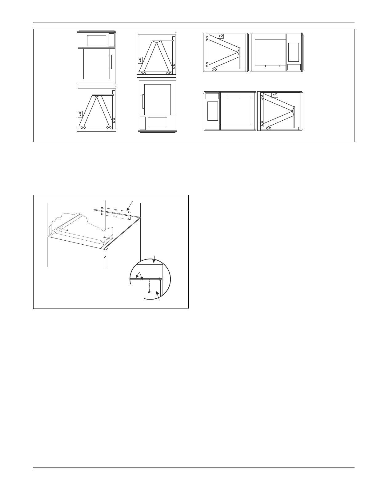
FIGURE 1: Typical Installation with MC Multi-Position Coils
UPFLOW
DOWNFLOW
HORIZONTAL RIGHT
HORIZONTAL LEFT
DOWNFLOW AND HORIZONTAL CONVERSION
These air handler units are supplied ready to be installed in a upflow,
downflow and left or right hand horizontal position.
If the unit is to be installed with an evaporator coil, refer to Figure 1 for
unit positioning information.
TIE PLATE
AIR HANDLER
COIL
COIL
UPFLOW & HORIZONTAL
APPLICATIONS
DOWNFLOW
APPLICATION
TOP PLATE
AIR HANDLER
FIGURE 2: Coil and Air Handler Attachment Details
AIR HANDLER AND COIL UPFLOW AND
HORIZONTAL
1. Apply neoprene gasket to top of coil casing.
2. Position blower casing over coil opening.
3. Attach tie plate to casings of air handler and coil using screws.
4. Remove blower access panel and coil filter door.
5. Disconnect wiring to blower motor. *Note location of wires as these
will be reconnected in a later step.
6. Remove blower motor and housing.
7. Fasten duct flanges of coil to duct flanges of air handler with
screws. See Figure 1.
8. Secure base of air handler to top of coil using screws.
9. Locate 2” wide foam gasket.
10. On the interior of the air handler/coil attachment point, apply foam
gasket over duct flanges on the sides and back.
11. Reinstall blower motor and housing by reversing the process in
Steps 3 and 4.
12. Complete electrical and blower speed connections as outlined in
other sections of this document.
13. Reposition and replace blower access panel.
AIR HANDLER AND COIL DOWNFLOW
1. Position blower casing over duct connection and secure such that
the supply air end of the blower is down.
2. Apply neoprene gasket to return-air side of air handler.
3. Place coil casing over blower return opening.
4. Attach tie plate to casings of air handler and coil using screws.
5. Remove blower access panel and coil filter door.
6. Disconnect wiring to blower motor.
*Note location of wires as these will be reconnected in a later step.
7. Remove blower motor and housing.
8. Fasten duct flanges of coil to base of air handler with screws. See
Figure 1.
9. Secure base of air handler to base of coil using screws.
10. Locate 2” wide foam gasket.
11. On the interior of the air handler/coil attachment point, apply foam
gasket over duct flanges on the sides and back.
12. Reinstall blower motor and housing by reversing the process in
Steps 3 and 4.
13. Complete electrical and blower speed connections as outlined in
other sections of this document.
14. Reposition and replace blower access panel.
3
Page 4
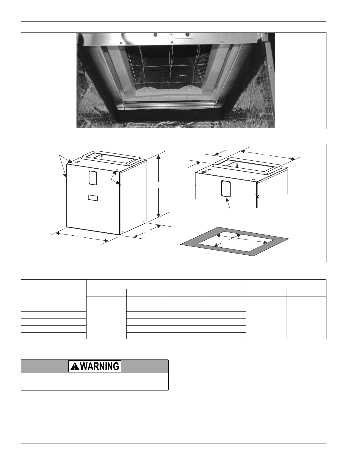
FIGURE 3: Gasket Location
J
K
B
A
22”
FIGURE 4: Dimensions & Duct Connection Dimensions
TABLE 1:
Dimensions
Dimensions
MA
MODELS
ABDE JK
Height Width Power Control
08B
17-1/2 16-1/2 14-19/32
12B 17-1/2 16-1/2 14-19/32
14D 24-1/2 23-1/2 21-19/32
25
16C 21 20 18-3/32
20D 24-1/2 23-1/2 21-19/32
1. Actual size (Conduit size).
DUCT CONNECTORS
Use 1/2" screws to connect ductwork to bottom of unit. Longer
screws will pierce the drain pan and cause leakage. If pilot holes
are drilled, drill only though field duct and unit bottom flange.
Air supply and return may be handled in one of several ways best
suited to the installation. See Figure 3 for dimensions for duct inlet and
outlet connections.
The vast majority of problems encountered with combination heating
and cooling systems can be linked to improperly designed or installed
duct systems. It is therefore highly important to the success of an installation that the duct system be properly designed and installed.
10-3/8”
CIRCUIT BREAKER
20-1/2”
PANEL
E
D
Wiring Knockouts
TOP OUTLET
DIMENSIONS
BOTTOM INLET
DIMENSIONS
1
7/8” (1/2”)
1 3/8” (1”)
7/8” (1/2”)
1 23/32” (1 1/4”)
Use flexible duct collars to minimize the transmission of vibration/noise
into the conditioned space. If electric heat is used, non-flammable
material must be used.
Where return air duct is short, or where sound may be a problem,
sound absorbing glass fiber should be used inside the duct. Insulation
of duct work is a must where it runs through an unheated space during
the heating season or through an uncooled space during the cooling
season. The use of a vapor barrier is recommended to prevent absorption of moisture from the surrounding air into the insulation.
The supply air duct should be properly sized by use of a transition to
match unit opening. All ducts should be suspended using flexible hangers and never fastened directly to the structure. This unit is not
designed for non-ducted (freeblow) applications. Size outlet plenum or
transition to discharge opening sizes shown in Figure 3.
4
Page 5
Duct work should be fabricated and installed in accordance with local
and/or national codes. This includes the standards of the National Fire
Protection Association for Installation of Air-Conditioning and Ventilating Systems, NFPA No. 90B.
AIR FILTERS
Air filters and filter racks must be field supplied.
.
Equipment should never be operated without filters.
SUSPENSION KITS
A suspension kit is available. Models 1BH0601 (unit size 018-060) is
designed specifically for the units contained in this instruction (upflow
application only). For installation of these accessory kits, see the
instructions packed with the kit.
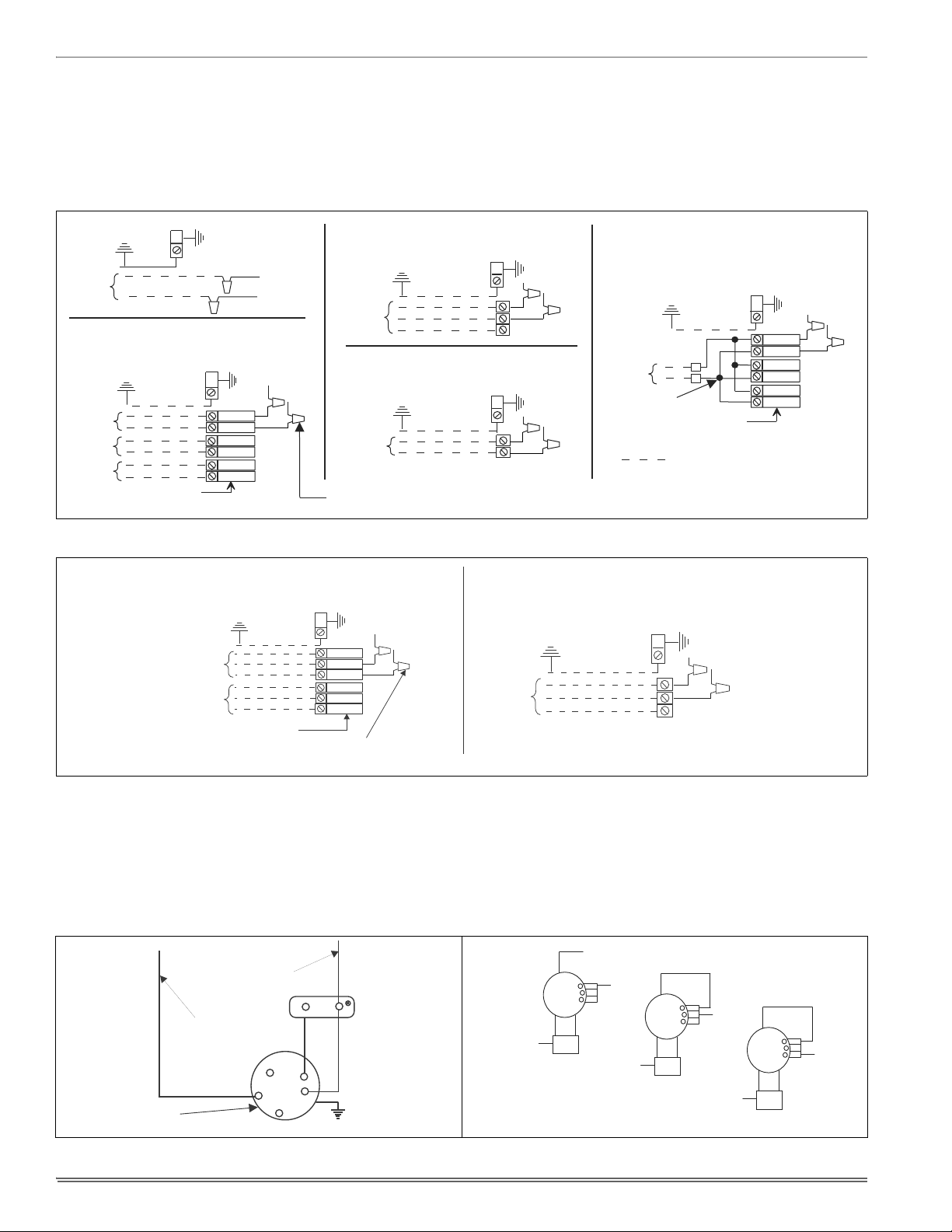
HORIZONTAL SUSPENSION
For suspension of these units in horizontal applications, it is recommended to use angle steel support brackets with threaded rods, supporting the units from the bottom, at the locations shown in Figure 4.
SUSPENSION SUPPORT LOCATIONS FOR HORIZONTAL APPLICATIONS
MIN. 3/8”
THREADED ROD
3-1/2 - 5 Ton 24” 53” - 58” 22”
FIGURE 5: Typical Horizontal Installation
SECTION IV: ELECTRIC HEATER
INSTALLATION
If the air handler requires electric heat, install the electric heat kit
according to the installation instructions included with the kit. After
installing the kit, mark the air handler nameplate to designate the heater
kit that was installed. If no heater is installed, mark the name plate
appropriately to indicate that no heat kit is installed.
The HEAT ENABLE jumper (See Figure 5) must be moved to the HEAT
position to enable operation of the heater.
Use only 4HK heater kits, as listed on Air Handler name plate and in
these Instructions. Use data from Tables 11 through 18 for information
on required minimum motor speed tap to be used for heating operation,
maximum over-current protection device required and minimum electrical supply wiring size required for listed combination of Air Handler and
Heater Kit.
For Upflow, Downflow and Horizontal right hand applications the kits
can be installed without modification.
Field modification is required for Horizontal left-hand airflow application
only. Follow instructions with heater for modification.
MIN. 1-1/2” x 1-1/2” Angle
Recommended length
26” minimum
with 2” clearance on
both sides of Air Handler
2
WW
Units
(Nominal Tons)
XX
Dimension
WW XX YY
1-1/2 - 3 Ton 16” 48” 22”
FIGURE 5: Typical Horizontal Installation
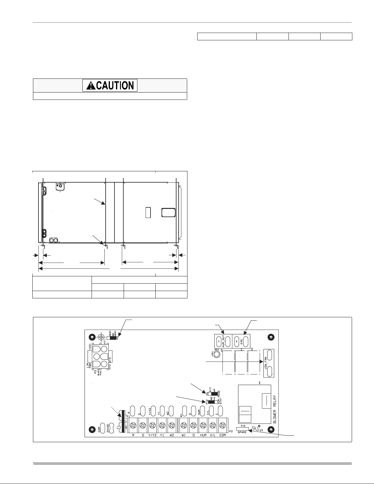
HEAT ENABLE
YY
JUMPER
1-1/2
MODE JUMPER
HUM OUT
RELAY OUTPUT
LOW FAN
RELAY OUTPUT
EAC RELAY
OUTPUT
HUM STAT JUMPER
FUSE
SPARE
JUMPER
FIGURE 6: Control Board
5
Page 6
SECTION V: LOW VOLTAGE CONTROL
CONNECTIONS
The 24 volt power supply is provided by an internally wired low voltage
transformer which is standard on all models, However, if the unit is connected to a 208 volt power supply, the low voltage transformer must be
rewired to the 208 volt tap. See the unit wiring label.
Field supplied low voltage wiring can exit the unit on the top right hand
corner or the right hand side panel. Refer to Figure 3.
Remove desired knockout and pierce foil faced insulation to allow wiring to pass through. Use as small of a hole as possible to minimize air
leakage.
Install a 7/8” plastic bushing in the selected hole and keep low voltage
wiring as short as possible inside the control box.
To further minimize air leakage, seal the wiring entry point at the outside
of the unit.
The field wiring is to be connected at the screw terminals of the control
board. Refer to Figures 10 & 11.
NOTICE
All wiring must comply with local and national electrical code requirements. Read and heed all unit caution labels.
NOTICE
It is possible to vary the amount of electric heat turned on during the
defrost cycle of a heat pump. Standard wiring will only bring on the
first stage of electric heat during defrost. See Heat Output and Limit
Connections and Table 6 for additional information on heat during
defrost cycle.
TABLE 2:
Terminal Signal Comment
The low voltage connections may be connected to the screw terminals
or the quick connect terminals. The screw terminals and the quick connect terminals are physically connected on the control board.
HUMIDITY SWITCH INPUT
The air handler control is designed to work with a humidity control that
closes when the humidity is below the set-point. The control is open
when the humidity is above the set-point. This humidity control may be
referred to as a humidistat or a dehumidistat.
The humidity switch controls both humidification and de-humidification
operation of the control. The control provides humidification using the
HUM OUT relay output and de-humidification by lowering the blower
Low Voltage Connections
R 24 VAC power (fused)
G Continuous Fan operation
Y/Y2
HUM Humidity switch input
COM 24 VAC common
Second or full stage
compressor operation
First stage compressor
Y1
operation
W2 Second stage heat operation
W1 First stage heat operation
O Reversing valve operation
Connection point for
X/L
heat pump fault indicator
Not used with outdoor units
having one stage compressors.
24 VAC will be present at this
terminal when the MODE
jumper is in the AC position.
This is normal.
24 VAC will be present at this
terminal when the HUM STAT
jumper is in the NO position.
This is normal.
This terminal is a connection
point only and does not affect
air handler control operation.
speed. This is accomplished using the LOW FAN output and a field
installed two-speed fan relay kit for non-variable speed models and the
de-humidification input of the motor for variable speed models. The
humidity switch should be connected to the R and HUM terminals of the
control. See Figures 10 & 11.
SECTION VI: REQUIRED CONTROL
SET-UP
IMPORTANT: The following steps must be taken at the time of installation to insure proper system operation.
1. Consult system wiring diagram to determine proper thermostat
wiring for your system.
2. If heat kit is installed, change HEAT ENABLE jumper from NO
HEAT to HEAT position.
3. If a humidstat is installed, change HUM STAT jumper from NO to
YES.
4. Set the MODE jumper to A/C (Air Conditioner) or HP (Heat Pump)
position depending on the outdoor unit included with the system.
FUNCTIONALITY AND OPERATION
Jumper Positions
Heat Enable Jumper
The HEAT ENABLE jumper configures the control for heat kit operation.
The jumper must be in the HEAT position if a heat kit is installed with
the air handler.
With the jumper in the NO HEAT position, the control will not energize
the heat relay outputs or sense the limit switch input.
If the jumper is not present, the control will operate as if the jumper is in
the HEAT position. If the jumper is not present and a heat kit is not present, the control will sense an open limit condition and the blower will run
continuously.
Hum Stat Jumper
The HUM STAT jumper configures the control to monitor the humidity
switch input. With the jumper in the NO position, the control will energize the HUM terminal with 24 VAC continually. With the jumper in the
YES position, the control will monitor the HUM input to control the HUM
OUT output to control an external humidifier.
If the jumper is not present, the control will operate as if the jumper is in
the YES position.
Mode Jumper
The MODE jumper configures the control to operate properly with an air
conditioner (AC position) or heat pump (HP position). With the jumper in
the AC position, the control will energize the O terminal with 24 VAC
continually. With the jumper in the HP position, the O input signal is
received from the room thermostat.
If the jumper is not present, the control will operate as if the jumper is in
the HP position.
SPARE Jumper
The control includes a spare jumper that can be used if a jumper is lost.
The SPARE jumper does not have any effect on the operation of the
control.
Status and Fault Codes
The control includes an LED that displays status and fault codes. These
codes are shown in Table 3. The control will display the fault codes until
power is removed from the control or the fault condition is no longer
present.
6
Page 7
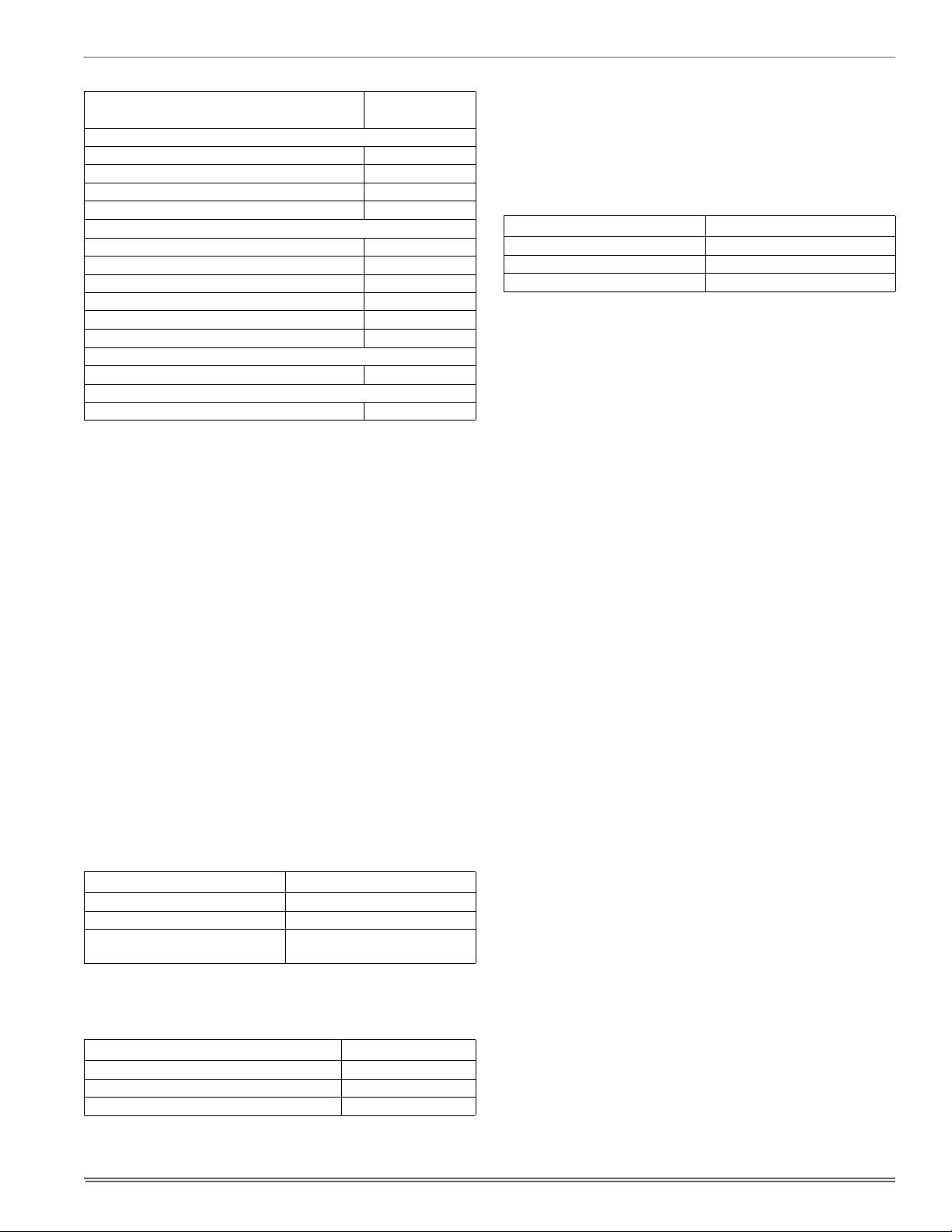
TABLE 3:
Status
No power to control OFF
Normal operation 2s ON / 2s OFF
Control in test mode Rapid Flash
Control failure ON
Limit Faults
Limit switch currently open (not in lockout) 1
Multiple limit openings with no call for heat 2
Multiple limit openings during one call for heat 3
Single long duration limit opening 4
Multiple long duration limit openings 5
Fan failure 6
Wiring Related Faults
Simultaneous call for heating and cooling 7
Internal Control Faults
Control recovered from internal event 9
Fault Codes
Fault or Status Condition
LED1 (RED)
Flash Code
External Relay Outputs
The control includes three outputs to drive external relays having 24
VAC coils. The outputs have a maximum rating of 1.0 Amp pilot duty at
24 VAC.
HUM OUT
The HUM OUT output can be used to drive an external relay or solenoid
(24 VAC coil) to control a humidifier. The output is energized when the
HUM input is energized, the HUM STAT is in the YES position, and the
control has a thermostat call for heating (heat pump or electric heat).
EAC
The EAC output can be used to drive an external relay (24 VAC coil) to
control an electronic air cleaner. The output is energized whenever the
blower relay on the control is energized. Models having a high efficiency non-variable speed motor use the EAC output as an input to the
motor. The EAC output can also be used to drive an electronic air
cleaner relay as long as the load of the EAC relay does not exceed 1.0
Amp. An additional connection to the EAC terminals must be made
using a piggyback terminal or similar device.
LOW FAN
The LOW FAN output can be used to drive an external relay (24 VAC
coil) that switches the power input to the motor to a lower speed tap. An
accessory kit is available for this application.
The LOW FAN output is energized when the control has the following
inputs.
TABLE 4:
Y/Y2 and HUM de-energized with
HUM STAT jumper in YES position
Low Fan Control Inputs
Input Operational Mode
G Continuous Fan operation
Y1 or Y1 and O First stage compressor operation
Dehumidification during cooling
Blower Delays
The control includes the following blower delays:
TABLE 5:
Condition Blower Delay
Following call for cooling 60 seconds
Following call for heat pump heating 30 seconds
Following call for electric heat heating 10 seconds
Blower Delays
Heat Output and Limit Connections
The control is connected to the heater relays and limit switch using the
6-pin connector. The relay outputs and the limit switch signal are 24
VDC.
The control energizes the heat relays and senses the limit switch input
as shown in Table 6 when the HEAT ENABLE jumper is in the HEAT
position.
TABLE 6:
The control energizes the first stage of electric heat immediately, the
second stage 10 seconds after the call for second stage heat, and the
third stage 20 seconds after the call for third stage heat.
Depending on the heat kit installed in the air handler, the control provides the flexibility to configure the amount of heat delivered with the
first stage heating call. As an example, when the control’s W1 input is
connected to the room thermostat’s first stage heat signal, a call for first
stage heat will energize one heating element (HT1). If the control’s W2
input is connected to the room thermostat’s first stage heat signal, a call
for first stage heat will energize two heating elements (HT1 & HT2).
With either configuration, the control will energize three heating elements (HT1, HT2, & HT3) when it receives a first and second stage
heat input from the thermostat.
Heat Relays
Input Heat Relay Output
W1 HT1
W2 HT1 and HT2
W1 and W2 HT1 and HT2 and HT3
Limit Switch and Lockout Operation
Limit Switch Operation
If the HEAT ENABLE jumper is in the HEAT position and the limit switch
opens (fault code 1), the control will immediately de-energize all electric
heat relay outputs and energize the blower (if it wasn’t already energized). When the limit switch closes, the control will re-energize electric
heat according to the thermostat inputs using normal timings.
Fan On Lock Condition
If the limit switch opens multiple times during a single call for electric
heat (fault code 3) or if the limit switch opens for a long duration (fault
code 4), the control will energize the blower until power is removed from
the control. The control will cycle the heat outputs on and off as the limit
re-closes and opens. The constant fan operation will signal the homeowner that a problem has occurred and a service call is required.
Soft Lockout
If the limit switch opens for a second long duration period during a single call for heat (fault code 5), the control will keep the blower locked on
and lock out the heat outputs for one hour. The control will only reset
this one hour lockout when the power is removed from the control. After
the one hour period has passed, the control will re-energize electric
heat according to the thermostat inputs using normal timings. The
blower will remain locked on from the first long duration limit opening.
Hard Lockout
The control has a hard lockout condition during which the control will
keep all heat outputs de-energized until power is removed from the control. The control de-energizes the blower five minutes after entering the
hard lockout condition.
If the limit switch closes and re-opens during the one hour soft lockout
period, the control will enter a hard lockout condition and continue to
indicate a fault code 5.
If the limit switch opens twice when no call for electric heat is present
(fault code 2), the control will enter a hard lockout condition.
If the limit switch opens multiple times soon after a soft lockout reset
(fault code 6), the control will enter a hard lockout condition.
Wiring Related Faults
If the control receives a simultaneous call for heating and cooling (fault
code 7), the control will perform both heating and cooling operations.
7
Page 8
SECTION VII: LINE POWER
ELECTRIC HEAT
WITHOUT CIRCUIT BREAKER
SINGLE SOURCE (2.5 - 10 KW)
GND. LUG
POWER
SUPPLY
GND.
LUG
ELECTRIC HEAT
WITHOUT CIRCUIT BREAKER
3 PHASE (10 - 15 KW)
GND. LUG
POWER
SUPPLY
GND.
LUG
1 PHASE ELECTRIC HEAT
WITH CIRCUIT BREAKER
AS SHIPPED FROM FACTORY
SINGLE SOURCE
(2.5 - 25 KW) - 25 KW SHOWN
GND. LUG
POWER
SUPPLY
GND.
LUG
1 PHASE ELECTRIC HEAT
WITH CIRCUIT BREAKER
& BREAKER BAR REMOVED
MULTI-SOURCE (15 - 25 KW) - 25 KW SHOWN
GND. LUG
POWER
SUPPLY 1
GND.
LUG
POWER
SUPPLY 2
POWER
SUPPLY 3
TYPICAL WIRING WITHOUT ELECTRIC HEAT
GND. LUG
POWER
SUPPLY
GND.
LUG
POWER WIRING (208/230-1-60)
NOTE: USE ONLY COPPER CONDUCTORS
TERMINAL
BLOCK
TERMINAL
BLOCK
MAYBE1,2,OR3
CIRCUIT BREAKERS
MAYBE1,2,OR3
CIRCUIT BREAKERS
(JUMPER BAR)
CONNECT LEADS WITH WIRE NUTS
(TYPICAL ALL HEAT KITS)
ELECTRIC HEAT
WITHOUT CIRCUIT BREAKER
3 PHASE (10 - 15 KW)
GND. LUG
POWER
SUPPLY
GND.
LUG
3 PHASE ELECTRIC HEAT
WITH CIRCUIT BREAKER
MULTI-SOURCE - 25 KW
GND. LUG
POWER
SUPPLY 1
GND.
LUG
POWER
SUPPLY 2
TERMINAL
BLOCK
CONNECT TRANSFORMER LEADS WITH WIRE NUTS
(TYPICAL ALL HEAT KITS)
(2) 3-PHASE
BREAKERS
FACTORY WIRED TO
TRANSFORMER
FACTORY WIRED TO
FAN MOTOR RELAY
TERMINAL ON
CONTROL BOARD
YEL
PUR
PUR
HIGH
MED
LOW
GND.
230 VOLT
BLOWER MOTOR
CAP
BRN
ORG
TAPE END & CAP
WITH WIRE NUT
L1
460 VOLT
BLOWER
MOTOR
L2
HIGH
HIGH
MED
LOW
PUR
BRN
460 VOLT BLOWER MOTOR
ORG
L1
460 VOLT
BLOWER
MOTOR
L2
MEDIUM
HIGH
MED
LOW
PUR
BRN
ORG
460 VOLT
BLOWER
MOTOR
L2
LOW
HIGH
MED
LOW
PUR
BRN
L1
CONNECTIONS
Power may be brought into the unit through the supply air end of the
unit (top when unit is vertical) or the left side panel. Use the hole appropriate to the unit’s orientation in each installation to bring conduit from
the disconnect. The power lead conduit should be terminated at the
electrical control box. To minimize air leakage, seal the wiring entry
point at the outside of the unit. See Figure 3.
Refer to Tables to determine proper wire sizing:
Tables 8 & 9 for cooling only or,
Tables 12 & 13 for single phase or,
Tables 15 & 16 for three phase or,
Table 18 for 460V.
FIGURE 7: Line Power Connections
FIGURE 8: 460V - Line Power Connections
SECTION VIII: BLOWER SPEED
CONNECTIONS
All air handlers contain 3-speed blower motors which are prewired to
the control board.
FIGURE 9: Blower Speed Connections FIGURE 10: 460V - Blower Speed Connections
8 Unitary Products Group
Adjust blower motor speed to provide airflow within the minimum and
maximum limits approved for evaporator coil, electric heat and outdoor
unit. Speed tap adjustments are made at the motor terminal block, See
Figure 8 or 9. Airflow data is shown in Tables 19 & 20.
Connect motor wires to motor speed tap receptacle for speed desired.
See wiring label for motor wiring details.
Page 9
SECTION IX: UNIT DATA
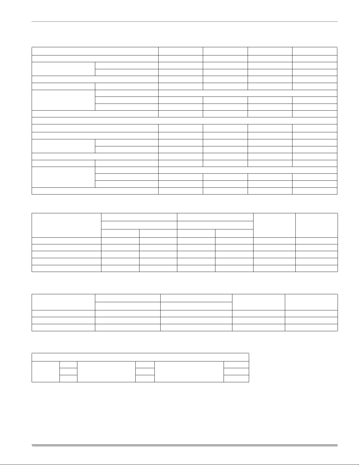
TABLE 7:
Models: MA MA08BN21 MA12BN21 MA12BN41 MA14DN21
Blower - Diameter x Width 10 x 9 10 x 9 10 x 9 10 x 10
Motor
Voltage 208/230 208/230 460 208/230
Amps Full Load 1.5 3.5 2.3 2.4
Permanent Filter
Shipping / Operating Weight (lbs.) 75/71 82/78 82/78 94/88
Models: MA MA16CN21 MA16CN41 MA20DN21 MA20DN41
Blower - Diameter x Width 10 x 10 10 x 10 11 x 10 11 x 10
Motor
Voltage 208/230 460 208/230 460
Amps Full Load 4.0 2.6 7.4 3.7
Permanent Filter
Shipping / Operating Weight (lbs.) 90/84 90/84 97/91 97/91
1. Field Supplied.
TABLE 8:
1. OCP = Over Current Protection device, must be HACR type Circuit Breaker or Time Delay fuse.
Physical and Electrical Data
HP 1/4 HP 3/4 HP 3/4 HP 1/2 HP
Nominal RPM 1075 1075 1075 1075
Type DISPOSABLE OR PERMANENT
1
Size 16 x 20 x 1 16 x 20 x 1 16 x 20 x 1 24 x 20 x 1
Filter Bulk Pack 1PF0601BK 1PF0601BK 1PF0601BK 1PF0604BK
HP 1 HP 1 HP 1 HP 1 HP
Nominal RPM 1075 1075 1075 1075
Type DISPOSABLE OR PERMANENT
1
Size 20 x 20 x 1 20 x 20 x 1 24 x 20 x 1 24 x 20 x 1
Filter Bulk Pack 1PF0602BK 1PF0602BK 1PF0604BK 1PF0604BK
Electrical Data - Cooling Only (60 Hz) - 208/230
Models
MA
Total Motor Amps Minimum Circuit Ampacity
60 Hertz 60 Hertz
208V230V208V230V
Max. O.C.P.
Amps/Type
1
Minimum Wire
Size A.W.G.
08BN21 1.4 1.5 1.8 1.9 15 14
12BN21 2.1 3.5 2.6 3.0 15 14
14DN21 3.3 2.4 4.1 4.4 15 14
16CN21 3.6 4.0 4.5 5.0 15 14
20DN21 4.8 7.4 6.0 6.5 15 14
TABLE 9:
Electrical Data - Cooling Only (60 Hz) - 460
Models
MA
Total Motor Amps Minimum Circuit Ampacity
60 Hertz 60 Hertz
Max. O.C.P.
Amps/Type
1
Minimum Wire
Size A.W.G.
12BN41 2.3 3.5 15 14
16CN41 2.6 3.9 15 14
20DN41 3.7 5.6 15 14
1. OCP = Over Current Protection device, must be HACR type Circuit Breaker or Time Delay fuse.
TABLE 10:
Conversion Table
KW & MBH Conversions - for Total Power Input Requirement
FOR
208V
230V 240V .918
OPERATION MULTIPLY
240V
.751
TABULATED KW & MBH BY
220V 240V .840
9
Page 10
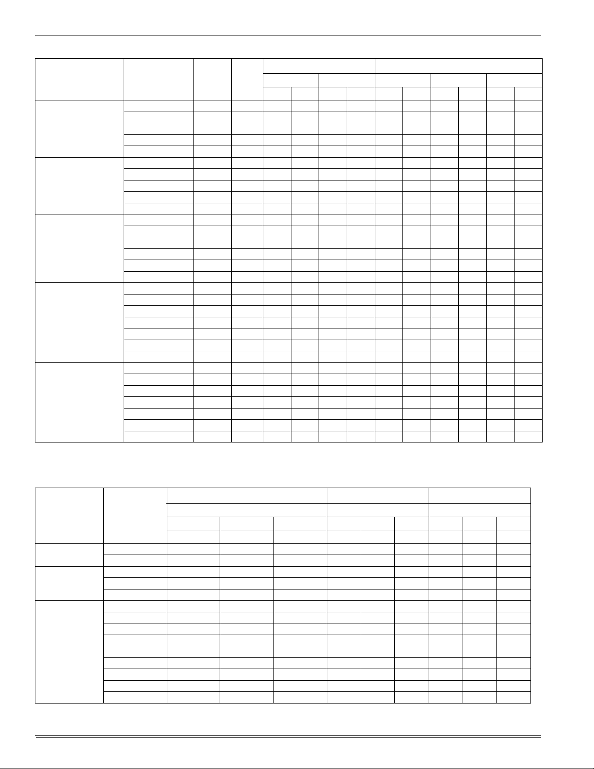
TABLE 11:
Electrical Data - 1 Ø - 208/230-1-60
Models
MA
Heat Kit - Single
Phase
4HK*6500206 0.5 Lo 1.9 2.5 6.4 8.5 1.9 2.5 1.9 2.5 1.9 2.5
4HK*6500506 0.5 Lo 3.6 4.8 12.3 16.4 3.6 4.8 3.6 4.8 3.6 4.8
08BN21
4HK*6500806 0.5 Med 5.6 7.5 19.2 25.6 2.8 3.75 5.6 7.5 5.6 7.5
4HK*6501006 0.5 Hi 7.2 9.6 24.6 32.8 3.6 4.8 7.2 9.6 7.2 9.6
4HK16501306 0.5 Hi 9.8 13.0 33.3 44.4 3.3 4.3 6.5 8.6 9.8 13.0
4HK*6500506 0.5 Lo 3.6 4.8 12.3 16.4 3.6 4.8 3.6 4.8 3.6 4.8
4HK*6500806 0.5 Med 5.6 7.5 19.2 25.6 2.8 3.75 5.6 7.5 5.6 7.5
12BN21
4HK*6501006 0.5 Med 7.2 9.6 24.6 32.8 3.6 4.8 7.2 9.6 7.2 9.6
4HK16501306 0.5 Med 9.8 13.0 33.3 44.4 3.3 4.3 6.5 8.6 9.8 13.0
4HK165N1506 0.5 Med 10.8 14.4 36.9 49.1 3.6 4.8 7.2 9.6 10.8 14.4
4HK*6500506 0.5 Lo 3.6 4.8 12.3 16.4 3.6 4.8 3.6 4.8 3.6 4.8
4HK*6500806 0.5 Lo 5.6 7.5 19.2 25.6 2.8 3.75 5.6 7.5 5.6 7.5
14DN21
4HK*6501006 0.5 Med 7.2 9.6 24.6 32.8 3.6 4.8 7.2 9.6 7.2 9.6
4HK16501506 0.5 Med 10.8 14.4 36.9 49.1 3.6 4.8 7.2 9.6 10.8 14.4
4HK16501806 0.5 Hi 13.2 17.6 45.1 60.1 3.3 4.4 6.6 8.8 13.2 17.6
4HK16502006 0.5 Hi 14.4 19.2 49.2 65.5 3.6 4.8 7.2 9.6 14.4 19.2
4HK*6500506 0.5 Lo 3.6 4.8 12.3 16.4 3.6 4.8 3.6 4.8 3.6 4.8
4HK*6500806 0.5 Lo 5.6 7.5 19.2 25.6 2.8 3.75 5.6 7.5 5.6 7.5
4HK*6501006 0.5 Med 7.2 9.6 24.6 32.8 3.6 4.8 7.2 9.6 7.2 9.6
16CN21
4HK16501306 0.50 Med 9.8 13 33.3 44.4 3.3 4.3 6.5 8.7 9.8 13.0
4HK16501506 0.5 Med 10.8 14.4 36.9 49.1 3.6 4.8 7.2 9.6 10.8 14.4
4HK16501806 0.5 Hi 13.2 17.6 45.1 60.1 3.3 4.4 6.6 8.8 13.2 17.6
4HK16502006 0.5 Hi 14.4 19.2 49.2 65.5 3.6 4.8 7.2 9.6 14.4 19.2
4HK*6500806 0.5 Lo 5.6 7.5 19.2 25.6 2.8 3.75 5.6 7.5 5.6 7.5
4HK*6501006 0.5 Lo 7.2 9.6 24.6 32.8 3.6 4.8 7.2 9.6 7.2 9.6
4HK16501306 0.50 Med 9.8 13 33.3 44.4 3.3 4.3 6.5 8.7 9.8 13.0
20DN21
4HK16501506 0.5 Med 10.8 14.4 36.9 49.1 3.6 4.8 7.2 9.6 10.8 14.4
4HK16501806 0.5 Med 13.2 17.6 45.1 60.1 3.3 4.4 6.6 8.8 13.2 17.6
4HK16502006 0.5 Med 14.4 19.2 49.2 65.5 3.6 4.8 7.2 9.6 14.4 19.2
4HK16502506 0.5 Med 18.0 24.0 61.5 81.9 3.6 4.8 10.8 14.4 18.0 24.0
1. See conversion Table 10.
* May be 0 (no breaker) or 1 (with breaker).
Max.
Static
Min.
Speed
Tap
Total Heat
1
KW Staging
KW MBH W1 Only W2 Only W1 + W2
208V 240V 208V 240V 208V 240V 208V 240V 208V 240V
TABLE 12:
Electrical Data - (For
Multi-Source
Power Supply) - Copper Wire 1 Ø - 208/230-1-60
Min. Circuit Ampacity
Models
MA
Heater
Model
1st 2nd 3rd 1st 2nd 3rd 1st 2nd 3rd
Circuit Circuit Circuit
208/240 208/240 208/240 208/240 208/240 208/240 208/240 208/240 208/240
12BN21
4HK16501306 41.8/49.5 19.5/22.5 – 45/50 20 / 25 – 8/8 10/10 –
4HK165N1506 47.5/54.4 21.7/25.0 – 50/60 25 / 25 – 8/6 10/10 –
4HK16501506 47.8/55.0 21.7/25.0 – 50/60 25 / 25 – 8/6 10/10 –
14DN21
4HK16501806 44.2/50.8 39.7/45.8 – 50/60 40 / 50 – 8/6 8/8 –
4HK16502006 47.8/55.0 43.3/50.0 – 50/60 45 / 50 – 8/6 8/8 –
4HK16501306 42.2/48.9 22.9/26.0 – 50/50 30/30 – 6/6 12/10 –
16CN21
4HK16501506 47.8/55.0 21.7/25.0 – 50/60 25 / 25 – 8/6 10/10 –
4HK16501806 44.2/50.8 39.7/45.8 – 50/60 40 / 50 – 8/6 8/8 –
4HK16502006 47.8/55.0 43.3/50.0 – 50/60 45 / 50 – 8/6 8/8 –
4HK16501306 43.5/49.9 24.2/27.0 – 50/50 30/30 – 6/6 10/10 –
4HK16501506 49.3/56.5 21.7/25.0 – 50/60 25 / 25 – 8/6 10/10 –
20DN21
4HK16501806 45.7/52.3 39.7/45.8 – 50/60 40 / 50 – 8/6 8/8 –
4HK16502006 49.3/56.5 43.3/50.0 – 50/60 45 / 50 – 8/6 8/8 –
4HK16502506 49.3/56.5 43.3/50.0 21.7/25.0 50/60 45 / 50 25/25 8/6 8/8 10/10
1. O.C.P. = Over Current Protection device, must be HACR type Circuit Breaker or Time Delay fuse.
10
Max. O.C.P.
1
Amps/Type
75°C Wire Size - AWG
Page 11

TABLE 13:
Electrical Data - (For
Models
MA
Single Source
Heat Kit - Single
Phase*
Power Supply) - Copper Wire 1 Ø - 208/230-1-60
Heater
Amps
Min. Circuit Ampacity
240V 208V 240V 208V 240V 208V 240V
4HK*6500206 10.4 13.03 14.88 15 15 14 14
4HK*6500506 20.0 23.42 26.88 30 30 10 10
08BN21
4HK*6500806 31.3 35.60 41.00 40 45 8 8
4HK*6501006 40.0 45.08 51.88 50 60 8 6
4HK16501306 54.2 60.4 69.6 70 70 4 4
4HK*6500506 20.0 25.79 29.38 30 30 10 10
4HK*6500806 31.3 37.98 43.50 40 45 8 8
12BN21
4HK*6501006 40.0 47.46 54.38 50 60 8 6
4HK16501306 54.2 61.3 72.1 70 90 4 3
4HK165N1506 60.0 69.13 79.38 70 90 4 3
4HK*6500506 20.0 24.29 28.00 30 30 8 10
4HK*6500806 31.3 36.48 42.13 40 45 8 8
14DN21
4HK*6501006 40.0 45.96 53.00 50 60 8 6
4HK16501506 60.0 67.63 78.00 70 90 4 3
4HK16501806 73.3 82.07 94.63 90 100 4 3
4HK16502006 80.0 89.29 103.00 100 110 3 2
4HK*6500506 20.0 26.17 30.00 30 30 8 8
4HK*6500806 31.3 38.35 44.13 40 45 8 8
4HK*6501006 40.0 47.83 55.00 50 60 8 6
16CN21
4HK16501306 54.2 65.2 74.80 70 80 4 2
4HK16501506 60.0 69.50 80.00 70 90 4 3
4HK16501806 73.3 83.94 96.63 90 100 4 3
4HK16502006 80.0 91.17 105.00 100 110 3 2
4HK*6500806 31.3 42.60 48.38 45 50 8 8
4HK*6501006 40.0 52.08 59.25 60 60 8 6
4HK16501306 54.2 67.7 77.00 70 80 4 2
20DN21
4HK16501506 60.0 73.75 84.25 90 90 3 3
4HK16501806 73.3 88.19 100.88 90 110 3 2
4HK16502006 80.0 95.42 109.25 100 125 3 2
4HK16502506 100.0 117.08 134.25 125 150 1 1/0
1. O.C.P. = Over Current Protection device, must be HACR type Circuit Breaker or Time Delay fuse.
* May be 0 (no breaker) or 1 (with breaker).
Field Wiring
Max. O.C.P.
1
Amps/Type
75°C Wire Size - AWG
TABLE 14:
Electrical Data - 3 Ø - 208/230-3-60
Models
MA
Heat Kit -
Three Phase
Max.
Static
Min.
Speed
Tap
Total Heat
1
KW Staging
KW MBH W1 Only W2 Only W1 + W2
208V 240V 208V 240V 208V 240V 208V 240V 208V 240V
08B 4HK06501025 0.5 Hi 7.2 9.6 24.6 32.8 7.2 9.6 7.2 9.6 7.2 9.6
12B
4HK06501025 0.5 Med 7.2 9.6 24.6 32.8 7.2 9.6 7.2 9.6 7.2 9.6
4HK065N1525 0.5 Hi 10.8 14.4 36.9 49.1 10.8 14.4 10.8 14.4 10.8 14.4
4HK06501025 0.5 Med 7.2 9.6 24.6 32.8 7.2 9.6 7.2 9.6 7.2 9.6
14D
4HK06501525 0.5 Med 10.8 14.4 36.9 49.1 10.8 14.4 10.8 14.4 10.8 14.4
4HK06501825 0.5 Hi 12.9 17.2 44.7 58.7 12.9 17.2 12.9 17.2 12.9 17.2
4HK06501025 0.5 Med 7.2 9.6 24.6 32.8 7.2 9.6 7.2 9.6 7.2 9.6
16C
4HK06501525 0.5 Med 10.8 14.4 36.9 49.1 10.8 14.4 10.8 14.4 10.8 14.4
4HK06501825 0.5 Hi 12.9 17.2 44.7 58.7 12.9 17.2 12.9 17.2 12.9 17.2
4HK06501025 0.5 Lo 7.2 9.6 24.6 32.8 7.2 9.6 7.2 9.6 7.2 9.6
20D
4HK06501525 0.5 Med 10.8 14.4 36.9 49.1 10.8 14.4 10.8 14.4 10.8 14.4
4HK16501825 0.5 Med 12.9 17.2 44.7 58.7 12.9 17.2 12.9 17.2 12.9 17.2
4HK16502525 0.5 Med 18.0 24.0 61.4 81.4 9.0 12.0 18.0 24.0 18.0 24.0
1. See conversion Table 10.
11
Page 12

TABLE 15:
Electrical Data - (For
Multi-Source
Power Supply) - Copper Wire 3 Ø - 208/230-3-60
Min. Circuit Ampacity
Models
MA
Heater
Model
1st 2nd 3rd 1st 2nd 3rd 1st 2nd 3rd
Circuit Circuit Circuit
208/240 208/240 208/240 208/240 208/240 208/240 208/240 208/240 208/240
20D
1. O.C.P. = Over Current Protection device, must be HACR type Circuit Breaker or Time Delay fuse.
4HK16501825 31.1/35.1 22.4/25.9 – 35/40 25/35 – 8/8 10/10 –
4HK16502525 40.0/45.4 31.3/36.1 – 40/50 35/40 – 8/8 8/8 –
Max. O.C.P.
1
Amps/Type
75°C Wire Size - AWG
TABLE 16:
Electrical Data - (For
Models
MA
Single Source
Heat Kit -
Three Phase
Power Supply) - Copper Wire 3 Ø - 208/230-3-60
Heater
Amps
240V
Min. Circuit Ampacity
Max. O.C.P.
208V 240V 208V 240V 208V 240V
Field Wiring
1
Amps/Type
75°C Wire Size - AWG
08B 4HK06501025 23.1 26.8 30.8 30 35 10 8
12B
4HK06501025 23.1 27.6 31.9 30 35 10 8
4HK065N1525 34.7 40.1 47.8 45 50 8 8
4HK06501025 23.1 29.1 33.3 30 35 10 8
14D
4HK06501525 34.7 41.6 46.4 45 50 8 8
4HK06501825 41.4 48.9 56.1 50 60 8 6
4HK06501025 23.1 29.5 33.9 30 35 10 8
16C
4HK06501525 34.7 42.0 48.4 45 50 8 8
4HK06501825 41.4 49.3 56.8 50 60 6 6
20D
1. O.C.P. = Over Current Protection device, must be HACR type Circuit Breaker or Time Delay fuse.
2. Heaters are 3 Phase.
TABLE 17:
Electrical Data - 460-3-60
MA
Models
4HK06501025 23.1 33.8 38.1 35 40 8 8
4HK06501525 34.7 43.5 52.6 45 60 8 6
Heater
Models
MAX. STATIC & MIN. CFM
Static Taps 480V 480V 480V 480V 480V
Total Heat1 KW Staging
KW MBH W1 Only W2 Only W1 + W2
12BN41 4HK06501046 0.5” Med 9.6 3.28 9.6 9.6 9.6
16CN41
4HK06501046 0.5” Med 9.6 3.28 9.6 9.6 9.6
4HK06501546 0.5” Med 14.4 4.92 14.4 14.4 14.4
4HK06501046 0.5” Med 9.6 3.28 9.6 9.6 9.6
20DN41
4HK06501546 0.5” Med 14.4 4.92 14.4 14.4 14.4
4HK06502946 0.5” Med 28.8 9.84 14.4 28.8 28.8
TABLE 18:
Electrical Data - (For
MA
Models
Single Source
Heater
Models
Power Supply) - Copper Wire 3 Ø - 460-3-60
Min. Circuit Ampacity Max. O.C.P.
480V 480V 480V
12BN41 4HK06501046 17.4 20 12
16CN41
4HK06501046 17.8 25 10
4HK06501546 24.9 25 10
4HK06501046 19.1 25 10
20DN41
4HK06501546 26.3 30 8
4HK06502946 48.0 50 8
1. OCP = Over Current Protection device, must be HACR type Circuit Breaker or Time Delay fuse.
12
Field Wiring
1
Amps/Type
Wire Size - AWG
75°C
Page 13

TABLE 19:
Air Flow Data - 60 Hz Models (230 & 460 Volt)
230 / 460 Volt - 60 Hz
Models
MA
08B
12B
14D
16C
20D
1. Includes return air filter, coil, and 10kW electric heater.
All MA series air handler units are UL Listed up to 0.50" w.c. external static pressure, including air filter, wet coil, and largest KW size heater.
ModelsMCBlower Motor
Speed
High 1102 986 870 754 638
MC18B
Med. 831 737 644 551 457
Low 615 537 458 379 300
High 1112 1001 890 780 669
MC24B
Med. 851 759 667 576 484
Low 643 562 480 399 317
MC30B
MC35B
High 1429 1363 1290 1212 1133
Med. 1213 1153 1097 1037 977
Low 1075 1032 990 927 873
High 1607 1533 1463 1395 1319
MC36B
Med. 1308 1258 1197 1146 1097
Low 1148 1108 1061 1017 976
High 1462 1396 1322 1254 1172
MC43B
Med. 1205 1154 1102 1046 980
Low 1075 1020 969 906 842
High 1715 1671 1608 1547 1460
MC48D
Med. 1471 1438 1367 1318 1263
Low 1379 1330 1276 1227 1157
High 1763 1713 1649 1581 1511
MC60D
Med. 1487 1462 1412 1356 1280
Low 1381 1353 1292 1225 1186
High 1746 1699 1655 1579 1486
MC62D
Med. 1486 1442 1393 1333 1270
Low 1392 1336 1285 1226 1158
High 1959 1874 1802 1708 1606
MC42C
Med. 1631 1587 1542 1473 1395
Low 1447 1431 1401 1363 1304
MC43C
MC35C
High 1825 1742 1660 1578 1486
Med. 1637 1572 1507 1431 1361
Low 1510 1456 1403 1341 1278
High 2018 1895 1772 1649 1525
MC48C
Med. 1684 1595 1506 1417 1328
Low 1561 1476 1392 1308 1223
High 1830 1748 1670 1590 1518
MC60C
Med. 1638 1573 1510 1443 1370
Low 1522 1479 1426 1364 1314
High 2226 2190 2103 2035 1931
MC48D
Med. 2115 2087 2017 1951 1851
Low N/A N/A N/A 1716 1643
High 2326 2235 2192 2107 2027
MC60D
Med. 2150 2089 2036 2008 1944
Low 2012 1923 1834 1718 1676
High 2357 2321 2254 2191 2139
MC62D
Med. 2212 2144 2111 2069 1986
Low 2066 1934 1910 1817 1723
1
@ External Static Pressure - IWC
CFM
0.1 0.2 0.3 0.4 0.5
0.6 0.7 0.8 0.9 1
521 405 289 173 57
364 271 178 84 N/A
221 142 63 N/A N/A
558 447 336 225 114
392 300 208 116 25
236 154 73 N/A N/A
1037 929 670 534 375
896 697 549 453 220
770 611 494 405 212
1044 851 725 673 673
887 742 648 608 609
807 690 613 582 582
1067 941 693 585 464
897 704 560 441 220
735 592 470 364 190
1338 1232 1003 727 508
1180 920 824 587 503
1047 866 681 567 392
1407 1276 995 852 N/A
1210 1087 795 726 N/A
1057 863 780 669 N/A
1399 1264 1093 796 581
1189 1081 776 628 450
1061 882 740 680 445
1486 1408 1264 953 810
1315 1218 967 821 533
1241 1098 844 751 712
1396 1306 1187 802 577
1276 1171 1043 722 493
1202 1088 785 684 456
1402 1279 1156 1033 910
1240 1151 1062 973 884
1139 1055 970 896 801
1428 1320 1199 772 543
1289 1185 992 679 475
1218 1114 885 652 487
1845 1683 1541 1465 1328
1744 1542 1466 1406 1254
1554 1451 1379 1292 1151
1906 1786 1538 1469 1368
1852 1692 1499 1416 1295
1600 1447 1389 1311 1200
1951 1859 1656 1556 1472
1862 1727 1566 1498 1369
1646 1514 1442 1381 1245
13
Page 14

TABLE 20:
Air Flow Data - 60 Hz Models (208 Volt)
208 Volt - 60 Hz
Models
MA
08B
12B
14D
16C
20D
1. Includes return air filter, coil, and 10kW electric heater.
All MA series air handler units are UL Listed up to 0.50" w.c. external static pressure, including air filter, wet coil, and largest KW size heater.
ModelsMCBlower Motor
Speed
High 1080 964 848 732 615
MC18B
Med. 712 628 544 461 377
Low 529 452 376 299 223
High 1039 932 825 717 610
MC24B
Med. 743 659 575 491 407
Low 532 460 387 315 242
MC30B
MC35B
High 1399 1339 1267 1192 1098
Med. 1080 1039 994 943 876
Low 932 895 868 829 776
High 1434 1267 1099 932 764
MC36B
Med. 1083 955 827 699 571
Low 933 818 703 588 473
High 1444 1377 1311 1247 1172
MC43B
Med. 1086 1047 1005 959 905
Low 942 920 887 827 768
High 1549 1498 1448 1383 1325
MC48D
Med. 1275 1269 1225 1181 1115
Low 1190 1162 1112 1074 975
High 1545 1490 1463 1378 1337
MC60D
Med. 1266 1248 1207 1140 1101
Low 1192 1186 1126 1067 992
High 1564 1520 1455 1400 1336
MC62D
Med. 1303 1262 1225 1165 1117
Low 1204 1161 1104 1060 1001
High 1782 1712 1619 1524 1435
MC42C
Med. 1468 1415 1355 1298 1233
Low 1310 1278 1239 1185 1125
MC35C
MC43C
High 1771 1705 1619 1528 1450
Med. 1486 1445 1393 1325 1265
Low 1314 1300 1258 1214 1164
High 1983 1865 1747 1629 1511
MC48C
Med. 1529 1446 1363 1280 1197
Low 1312 1249 1185 1122 1059
High 1819 1738 1657 1570 1491
MC60C
Med. 1489 1452 1409 1349 1293
Low 1321 1310 1271 1233 1184
High 2250 2180 2139 2062 1971
MC48D
Med. 1953 1956 1905 1858 1755
Low N/A N/A 1544 1538 1455
High 2251 2186 2144 2073 2003
MC60D
Med. 1987 1945 1926 1887 1836
Low 1492 1517 1521 1523 1507
High 2208 2123 2092 2054 1910
MC62D
Med. 1959 1945 1913 1862 1766
Low N/A N/A N/A 1546 1491
1
@ External Static Pressure - IWC
CFM
0.1 0.2 0.3 0.4 0.5
0.6 0.7 0.8 0.9 1
499 383 267 150 34
293 210 126 42 N/A
146 70 N/A N/A N/A
502 395 288 180 73
323 239 156 72 N/A
169 97 24 N/A N/A
1023 915 673 534 377
778 639 525 415 211
656 543 447 351 214
597 430 262 95 N/A
443 315 187 59 N/A
359 244 129 14 N/A
1091 971 721 573 442
819 647 534 438 220
655 536 477 366 209
1235 1125 936 658 548
997 811 684 548 392
817 737 625 493 358
1231 1115 850 739 572
1005 839 687 564 469
842 740 638 507 347
1257 1154 813 755 549
1028 827 744 590 398
870 745 554 532 462
1323 1213 985 798 557
1144 1005 791 669 493
1045 934 725 561 424
1361 1261 1102 721 504
1198 1041 791 663 457
1108 891 753 550 410
1393 1275 1157 1039 921
1114 1031 948 865 782
995 932 868 805 742
1396 1289 1178 777 544
1207 1112 834 627 475
1120 1022 725 583 419
1855 1683 1553 1461 1342
1649 1528 1440 1355 1245
1401 1346 1285 1195 1081
1921 1809 1574 1478 1370
1761 1643 1472 1387 1213
1436 1379 1308 1213 1128
1762 1595 1496 1435 1298
1661 1513 1420 1315 1182
1407 1354 1258 1184 1088
14
Page 15

FIGURE 11: Cooling Models with Electric Heat Wiring
MA SERIES - Air Handler Control Wiring
Typical A/C - Cooling only Applications
THERMOSTAT
AIR HANDLER
BOARD
1-STAGE
AIR CONDITIONING
RR
G
Y
W1
W2
C
G
W1
W2
Y
C
Y/Y2
Y1
O
HUM
X/L
COM
HUMIDISTAT
*
THERMOSTAT
AIR HANDLER
BOARD
1-STAGE
AIR CONDITIONING
RR
G
Y
W1
W2
C
G
W1
W2
Y
C
Y/Y2
Y1
O
HUM
X/L
COM
HUMIDISTAT
*
MA SERIES - Air Handler Control Wiring
Typical A/C with Electric Heat Applications
* Optional dehumidification humidistat switch contacts open on humidity rise.
Notes:
1. “Y” Terminal on Air Handler Control Board must be connected for full CFM and applications requiring 60 second blower off delay for SEER enhancement.
2. Move HUM STAT Jumper on AH Control Board to YES position if Humidistat is used.
3. MODE Jumper on AH control board should be set to A/C for air conditioners.
CONTROL WIRING - AHP or MA Series Air Handler
And Newer UPG Single Stage HP Systems
Single Stage H/P with Standard Demand Defrost Control Board
THERMOSTAT
R
G
Y
AIR HANDLER
BOARD
R
G
Y/Y2
HEAT PUMP
R
Y
Y1
W2
E
W/W1
O
X/L
C
W2
W1
O
HUM
X/L
COM
HUMIDISTAT
W1 66
W
O
*
X/L
C
FIGURE 12: Single-Stage Cooling Wiring
* Optional dehumidification humidistat switch contacts open on rise.
Notes:
1. “Y” Terminal on Air Handler Control Board must be connected for full CFM and applications requiring 60 second blower off delay for SEER enhancement.
2. Move HUM STAT Jumper on AH Control Board to YES position if Humidistat is used.
3. MODE Jumper on AH control board should be set to HP for heat pumps.
4. To change quantity of heat during HP defrost cycle - Reverse connections at W1 & W2 on Air Handler Control Board.
SECTION X: MAINTENANCE
Filters must be cleaned or replaced when they become dirty. Inspect at
least once per month. The frequency of cleaning depends upon the
hours of operation and the local atmospheric conditions. Clean filters
keep unit efficiency high.
15
LUBRICATION
The bearings of the blower motor are permanently lubricated.
Page 16

SECTION XI: WIRING DIAGRAM
Thermo Products, LLC
5235 West State Road 10
North Judson, IN 46366
www.thermopride.com
Copyright © 2012 by Johnson Controls, Inc. All rights reserved.
FIGURE 13: Wiring Diagram
Page 17

MODULAR
INSTALLATION MANUAL
MAC-226
ECN 5287-MA 121005
VARIABLE SPEED AIR HANDLERS
MODELS: MV
LIST OF SECTIONS
GENERAL . . . . . . . . . . . . . . . . . . . . . . . . . . . . . . . . . . . . . . . . . . . . . . 1
SAFETY . . . . . . . . . . . . . . . . . . . . . . . . . . . . . . . . . . . . . . . . . . . . . . . . 1
UNIT INSTALLATION . . . . . . . . . . . . . . . . . . . . . . . . . . . . . . . . . . . . . 2
ELECTRIC HEATER INSTALLATION . . . . . . . . . . . . . . . . . . . . . . . . 5
LOW VOLTAGE CONTROL CONNECTIONS . . . . . . . . . . . . . . . . . . 5
REQUIRED CONTROL SET-UP . . . . . . . . . . . . . . . . . . . . . . . . . . . . .8
LIST OF FIGURES
Typical Installation with MC or FC Evaporator Coil . . . . . . . . . . . . . . .3
Coil and Air Handler Attachment Details . . . . . . . . . . . . . . . . . . . . . . .3
Gasket Location . . . . . . . . . . . . . . . . . . . . . . . . . . . . . . . . . . . . . . . . . .4
Dimensions & Duct Connection Dimensions . . . . . . . . . . . . . . . . . . . . 4
Typical Horizontal Installation . . . . . . . . . . . . . . . . . . . . . . . . . . . . . . . 5
Air Handler Control Board – Communications Connections . . . . . . . .6
LIST OF TABLES
Dimensions . . . . . . . . . . . . . . . . . . . . . . . . . . . . . . . . . . . . . . . . . . . . . 4
Low Voltage Connections . . . . . . . . . . . . . . . . . . . . . . . . . . . . . . . . . . 6
Fault Codes . . . . . . . . . . . . . . . . . . . . . . . . . . . . . . . . . . . . . . . . . . . . .9
Heat Relays . . . . . . . . . . . . . . . . . . . . . . . . . . . . . . . . . . . . . . . . . . . . . 9
Comfort Setting Selection . . . . . . . . . . . . . . . . . . . . . . . . . . . . . . . . . 10
Physical and Electrical Data - Cooling Only (60 Hz) . . . . . . . . . . . . . 11
Electrical Data - Cooling Only (60 Hz) . . . . . . . . . . . . . . . . . . . . . . . . 11
Conversion Table . . . . . . . . . . . . . . . . . . . . . . . . . . . . . . . . . . . . . . . . 11
Electrical Data - 1 Ø - 208/230-1-60 . . . . . . . . . . . . . . . . . . . . . . . . . 12
Electrical Data - 208/230-3-60 . . . . . . . . . . . . . . . . . . . . . . . . . . . . . . 12
ISO 9001
Certified Quality
Management System
LINE POWER CONNECTIONS . . . . . . . . . . . . . . . . . . . . . . . . . . . . . 9
AIRFLOW AND COMFORT SETTING SELECTION . . . . . . . . . . . . 10
UNIT DATA . . . . . . . . . . . . . . . . . . . . . . . . . . . . . . . . . . . . . . . . . . . 11
MAINTENANCE . . . . . . . . . . . . . . . . . . . . . . . . . . . . . . . . . . . . . . . . 16
WIRING DIAGRAM . . . . . . . . . . . . . . . . . . . . . . . . . . . . . . . . . . . . . 16
Cooling Models with and without Electric Heat Wiring . . . . . . . . . . . . 7
Two-Stage Heat Pump Wiring . . . . . . . . . . . . . . . . . . . . . . . . . . . . . . 7
Air Handler with Communicating AC or HP . . . . . . . . . . . . . . . . . . . . 8
Line Power Connections . . . . . . . . . . . . . . . . . . . . . . . . . . . . . . . . . . 10
Wiring Diagram . . . . . . . . . . . . . . . . . . . . . . . . . . . . . . . . . . . . . . . . . 16
Electrical Data - (For Single Source Power Supply) -
Copper Wire 1 Ø - 208/230-1-60 . . . . . . . . . . . . . . . . . . . . . . . . . . . 13
Electrical Data - (For Single Source Power Supply) -
Copper Wire - 208/230-3-60 . . . . . . . . . . . . . . . . . . . . . . . . . . . . . . . 13
Electrical Data - (For Multi-Source Power Supply) -
Copper Wire 1 Ø - 208/230-1-60 . . . . . . . . . . . . . . . . . . . . . . . . . . . 14
Electrical Data - (For Multi-Source Power Supply) -
Copper Wire - 208/230-3-60 . . . . . . . . . . . . . . . . . . . . . . . . . . . . . . . 14
Air Handler Air Flow Data . . . . . . . . . . . . . . . . . . . . . . . . . . . . . . . . . 15
SECTION I: GENERAL
This modular air handler provides the flexibility for installation in any
upflow, downflow, or horizontal application. These versatile models may
be used for cooling or heat pump operation with or without electric heat.
A BRAND LABEL (available from Distribution) may be applied to the
center of the blower access panel.
The unit can be positioned for bottom return air in the upflow position,
top return air in the downflow position, and right or left return in the horizontal position.
Top and side power wiring and control wiring, accessible screw terminals for control wiring and easy to install electric heaters all combine to
make the installation easy, and minimize installation cost.
SECTION II: SAFETY
This is a safety alert symbol. When you see this symbol on
labels or in manuals, be alert to the potential for personal
injury.
Understand and pay particular attention to the signal words DANGER,
WAR NIN G, or CAUTION.
DANGER indicates an imminently hazardous situation, which, if not
avoided, will result in death or serious injury
WAR NIN G indicates a potentially hazardous situation, which, if not
avoided, could result in death or serious injury
CAUTION indicates a potentially hazardous situation, which, if not
avoided may result in minor or moderate injury.
alert against unsafe practices and hazards involving only property damage.
.
.
It is also used to
Improper installation may create a condition where the operation of
the product could cause personal injury or property damage.
Improper installation, adjustment, alteration, service or maintenance can cause injury or property damage. Refer to this manual
for assistance or for additional information, consult a qualified contractor, installer or service agency.
This product must be installed in strict compliance with the installation instructions and any applicable local, state, and national codes
including, but not limited to building, electrical, and mechanical
codes.
FIRE OR ELECTRICAL HAZARD
Failure to follow the safety warnings exactly could result in serious
injury, death or property damage.
A fire or electrical hazard may result causing property damage, personal injury or loss of life.
Page 18

1. Install this air handler only in a location and position as specified in
SECTION III of these instructions.
2. Always install the air handler to operate within the air handler’s
intended maximum outlet air temperature. Only connect the air
handler to a duct system which has an external static pressure
within the allowable range, as specified on the air handler rating
plate.
3. When an air handler is installed so that supply ducts carry air circulated by the air handler to areas outside the space containing
the air handler, the return air shall also be handled by duct(s)
sealed to the air handler casing and terminating outside the space
containing the air handler.
4. The air handler is not to be used for temporary heating of buildings
or structures under construction.
5. The size of the unit should be based on an acceptable heat loss or
gain calculation for the structure. ACCA, Manual J or other
approved methods may be used.
SAFETY REQUIREMENTS
1. This air handler should be installed in accordance with all national
and local building/safety codes and requirements, local plumbing
or wastewater codes, and other applicable codes.
2. Refer to the unit rating plate for the air handler model number, and
then see the dimensions page of this instruction for supply air plenum dimensions in Figure 3. The plenum must be installed according to the instructions.
3. Provide clearances from combustible materials as listed under
Clearances to Combustibles.
4. Provide clearances for servicing ensuring that service access is
allowed for electric heaters and blower.
5. Failure to carefully read and follow all instructions in this manual
can result in air handler malfunction, death, personal injury and/or
property damage.
6. Check the rating plate and power supply to be sure that the electrical characteristics match.
7. Air handler shall be installed so the electrical components are protected from water.
8. Installing and servicing heating/cooling equipment can be hazardous due to the electrical components. Only trained and qualified
personnel should install, repair, or service heating/cooling equipment. Untrained service personnel can perform basic maintenance
functions such as cleaning and replacing the air filters. When
working on heating/cooling equipment, observe precautions in the
manuals and on the labels attached to the unit and other safety
precautions that may apply.
9. These instructions cover minimum requirements and conform to
existing national standards and safety codes. In some instances
these instructions exceed certain local codes and ordinances,
especially those who have not kept up with changing residential
and non-HUD modular home construction practices. These
instructions are required as a minimum for a safe installation.
INSPECTION
As soon as a unit is received, it should be inspected for possible damage during transit. If damage is evident, the extent of the damage
should be noted on the carrier’s freight bill. A separate request for
inspection by the carrier’s agent should be made in writing. Also, before
installation the unit should be checked for screws or bolts, which may
have loosened in transit. There are no shipping or spacer brackets
which need to be removed.
Also check to be sure all accessories such as heater kits, suspension
kits, and coils are available. Installation of these accessories or field
conversion of the unit should be accomplished before setting the unit in
place or connecting any wiring, electric heat, ducts or piping.
LIMITATIONS
These units must be wired and installed in accordance with all national
and local safety codes.
Voltage limits are as follows:
Air Handler Voltage Voltage code
208/230-1-60 21 187-253
1. Rated in accordance with ARI Standard 110, utilization range “A”.
Airflow must be within the minimum and maximum limits approved for
electric heat, evaporator coils and outdoor units.
Entering Air Temperature Limits
Wet Bulb Temp.°F Dry Bulb Temp. °F
Min. Max. Min. Max.
57 72 65 95
Normal Operating
Voltage Range
1
SECTION III: UNIT INSTALLATION
CLEARANCES
Clearances must be taken into consideration, and provided for as follows:
1. Refrigerant piping and connections - minimum 12” recommended.
2. Maintenance and servicing access - minimum 36” from front of unit
recommended for blower motor / coil replacement.
3. Condensate drain lines routed to clear filter and panel access.
4. Filter removal - minimum 36” recommended.
5. A combustible floor base accessory is available for downflow
applications of this unit, if required by local code.
LOCATION
Location is usually predetermined. Check with owner’s or dealer’s
installation plans. If location has not been decided, consider the following in choosing a suitable location:
1. Select a location with adequate structural support, space for service access, clearance for air return and supply duct connections.
2. Use hanging brackets to wall mount unit as shown.
3. Normal operating sound levels may be objectionable if the air handler is placed directly over some rooms such as bedrooms, study,
etc.
4. Select a location that will permit installation of condensate line to
an open drain or outdoors allowing condensate to drain away from
structure.
5. When an evaporator coil is installed in an attic or above a finished
ceiling, an auxiliary drain pan should be provided under the air
handler as is specified by most local building codes.
6. Proper electrical supply must be available.
NOTICE
In severe high humidity, high temperature indoor unit environments,
seal completely with adequate fiberglass insulation using vapor
barrier on the outside.
2
Page 19

FIGURE 1: Typical Installation with MC or FC Evaporator Coil (MC required for horizontal applications)
UPFLOW
DOWNFLOW
HORIZONTAL RIGHT
HORIZONTAL LEFT
DOWNFLOW AND HORIZONTAL CONVERSION
These air handler units are supplied ready to be installed in a upflow,
downflow and left or right hand horizontal position.
If the unit is to be installed with an evaporator coil, refer to Figure 1 for
unit positioning information.
TIE PLATE
AIR HANDLER
COIL
COIL
UPFLOW & HORIZONTAL
APPLICATIONS
DOWNFLOW
APPLICATION
TOP PLATE
AIR HANDLER
FIGURE 2: Coil and Air Handler Attachment Details
AIR HANDLER AND COIL UPFLOW AND
HORIZONTAL
1. Apply neoprene gasket to top of coil casing.
2. Position blower casing over coil opening.
3. Attach tie plate to casings of air handler and coil using screws.
4. Remove blower access panel and coil filter door.
5. Disconnect wiring to blower motor. *Note location of wires as these
will be reconnected in a later step.
6. Remove blower motor and housing.
7. Fasten duct flanges of coil to duct flanges of air handler with
screws. See Figure 1.
8. Secure base of air handler to top of coil using screws.
9. Locate 2” wide foam gasket.
10. On the interior of the air handler/coil attachment point, apply foam
gasket over duct flanges on the sides and back.
11. Reinstall blower motor and housing by reversing the process in
Steps 3 and 4.
12. Complete electrical and blower speed connections as outlined in
other sections of this document.
13. Reposition and replace blower access panel.
AIR HANDLER AND COIL DOWNFLOW
1. Position blower casing over duct connection and secure such that
the supply air end of the blower is down.
2. Apply neoprene gasket to return-air side of air handler.
3. Place coil casing over blower return opening.
4. Attach tie plate to casings of air handler and coil using screws.
5. Remove blower access panel and coil filter door.
6. Disconnect wiring to blower motor.
*Note location of wires as these will be reconnected in a later step.
7. Remove blower motor and housing.
8. Fasten duct flanges of coil to base of air handler with screws. See
Figure 1.
9. Secure base of air handler to base of coil using screws.
10. Locate 2” wide foam gasket.
11. On the interior of the air handler/coil attachment point, apply foam
gasket over duct flanges on the sides and back.
12. Reinstall blower motor and housing by reversing the process in
Steps 3 and 4.
13. Complete electrical and blower speed connections as outlined in
other sections of this document.
14. Reposition and replace blower access panel.
3
Page 20

FIGURE 3: Gasket Location
J
K
B
FIGURE 4: Dimensions & Duct Connection Dimensions
TABLE 1:
Dimensions
Models
MV
ABDE JK
Height Width Power Control
12B
12D 24-1/2 23-1/2 21-19/32
16C 21 20 18-3/32
25
20D 24-1/2 23-1/2 21-19/32
1. Actual size (Conduit size).
10-3/8”
A
CIRCUIT BREAKER
PANEL
21-1/2”
20-1/2”
Dimensions
17-1/2 16-1/2 14-19/32
E
TOP OUTLET
DIMENSIONS
D
BOTTOM INLET
DIMENSIONS
Wiring Knockouts
1
7/8” (1/2”)
1 3/8” (1”)
7/8” (1/2”)
1 23/32” (1 1/4”)
DUCT CONNECTORS
Use 1/2" screws to connect ductwork to bottom of unit. Longer
screws will pierce the drain pan and cause leakage. If pilot holes
are drilled, drill only though field duct and unit bottom flange.
Air supply and return may be handled in one of several ways best
suited to the installation. See Figure 3 for dimensions for duct inlet and
outlet connections.
The vast majority of problems encountered with combination heating
and cooling systems can be linked to improperly designed or installed
duct systems. It is therefore highly important to the success of an installation that the duct system be properly designed and installed.
Use flexible duct collars to minimize the transmission of vibration/noise
into the conditioned space. If electric heat is used, non-flammable
material must be used.
4
Where return air duct is short, or where sound may be a problem,
sound absorbing glass fiber should be used inside the duct. Insulation
of duct work is a must where it runs through an unheated space during
the heating season or through an uncooled space during the cooling
season. The use of a vapor barrier is recommended to prevent absorption of moisture from the surrounding air into the insulation.
The supply air duct should be properly sized by use of a transition to
match unit opening. All ducts should be suspended using flexible hangers and never fastened directly to the structure. This unit is not
designed for non-ducted (freeblow) applications. Size outlet plenum or
transition to discharge opening sizes shown in Figure 3.
Duct work should be fabricated and installed in accordance with local
and/or national codes. This includes the standards of the National Fire
Protection Association for Installation of Air-Conditioning and Ventilating Systems, NFPA No. 90B.
Page 21

AIR FILTERS
Air filters and filter racks must be field supplied.
.
Equipment should never be operated without filters.
SUSPENSION KITS
A suspension kit is available. Models 1BH0601 (unit size 018-060) is
designed specifically for the units contained in this instruction (upflow
application only). For installation of these accessory kits, see the
instructions packed with the kit.
HORIZONTAL SUSPENSION
For suspension of these units in horizontal applications, it is recommended to use angle steel support brackets with threaded rods, supporting the units from the bottom, at the locations shown in Figure 4.
SUSPENSION SUPPORT LOCATIONS FOR HORIZONTALAPPLICATIONS
MIN. 3/8”
THREADED ROD
MIN. 1-1/2” x 1-1/2” Angle
Recommended length
26” minimum
with 2” clearance on
both sides of Air Handler
2
WW
Units
(Nominal Tons)
1-1/2 - 3 Ton 16” 48” 22”
3-1/2 - 5 Ton 24” 53” - 58” 22”
FIGURE 5: Typical Horizontal Installation
XX
Dimension
WW XX YY
1-1/2
YY
SECTION IV: ELECTRIC HEATER
INSTALLATION
If the air handler requires electric heat, install the electric heat kit
according to the installation instructions included with the kit. After
installing the kit, mark the air handler nameplate to designate the heater
kit that was installed. If no heater is installed, mark the name plate
appropriately to indicate that no heat kit is installed.
The HEAT ENABLE jumper (See Figure 5) must be moved to the HEAT
position to enable operation of the heater
Use only 4HK heater kits, as listed on Air Handler name plate and in
these Instructions. Use data from Tables 9 and 12 for information on
required minimum motor speed tap to be used for heating operation,
maximum over-current protection device required and minimum electrical supply wiring size required for listed combination of Air Handler and
Heater Kit.
For Upflow, Downflow and Horizontal right hand applications the kits
can be installed without modification.
Field modification is required for Horizontal left-hand airflow application
only. Follow instructions with heater for modification.
NOTICE
If a heat kit with a circuit breaker is installed in the air handler, the
circuit breaker cover cladding must be removed to gain access to
the sheet metal cover plate. Some local codes may require that the
circuit breaker remain visible. If so, do not re-install circuit breaker
cover cladding.
SECTION V: LOW VOLTAGE CONTROL
CONNECTIONS
This air handler can be connected to the wall thermostat and outdoor A/
C or heat pump using either conventional low voltage (24 VAC) thermostat wiring OR using four-wire digital communications wiring. To use
conventional low voltage wiring, see the section below entitled “Conventional Low Voltage Control Wiring”. To use four-wire communications control wiring, see the section below entitled “Control Wiring using
Communicating Controls”.
The Communicating System consists of several intelligent communicating components including the Communicating Thermostat Control
(touch-screen wall thermostat), variable speed air handler, air conditioner (15 and 18 SEER premium air conditioners) or heat pump (13, 15
and 18 SEER premium heat pumps), which continually communicate
with each other via a four-wire connection called the A-R-C-B. Commands, operating conditions, and other data are passed continually
between components over the A-R-C-B bus. See Figure 8. The result is
a new level of comfort, versatility, and simplicity.
In order to use this air handler in full communications (COMM) mode, it
MUST be installed with the matching touch-screen Communicating
Control (wall thermostat) and an outdoor air conditioner or heat pump
with a fully communicating control.
This air handler may also be used along with the Communicating Thermostat Control and a non-communicating outdoor air conditioner
through the addition of a communicating Outdoor Aux Control board to
the outdoor unit. This system allows full communication between the air
handler and thermostat and limited communication to the outdoor unit.
5
Page 22

FIGURE 6: Air Handler Control Board – Communications Connections
SPARE JUMPER
HEAT ENABLE JUMPER
HUMIDIFIER OUT PUT
EAC OUTPUT
THERMOSTAT CONNECTIONS
CONTINUOUS FAN JUMPER
BLOWER SPEED
JUMPERS
HUMIDSTAT
JUMPER
AC/HP JUMPER
CONVENTIONAL LOW VOLTAGE CONTROL WIRING
(24 VAC)
The 24 volt power supply is provided by an internally wired low voltage
transformer which is standard on all models, However, if the unit is connected to a 208 volt power supply, the low voltage transformer must be
rewired to the 208 volt tap. See the unit wiring label.
Field supplied low voltage wiring can exit the unit on the top right hand
corner or the right hand side panel. Refer to Figure 3.
Remove desired knockout and pierce foil faced insulation to allow wiring to pass through. Use as small of a hole as possible to minimize air
leakage.
Install a 7/8” plastic bushing in the selected hole and keep low voltage
wiring as short as possible inside the control box.
To further minimize air leakage, seal the wiring entry point at the outside
of the unit.
The field wiring is to be connected at the screw terminals of the control
board. Refer to Figure 6 or 7.
NOTICE
All wiring must comply with local and national electrical code
requirements. Read and heed all unit caution labels.
It is possible to vary the amount of electric heat turned on during the
defrost cycle of a heat pump. Standard wiring will only bring on the
first stage of electric heat during defrost. See Heat Output and Limit
Connections and Table 4 for additional information on heat during
defrost cycle.
TABLE 2:
Low Voltage Connections
Terminal Signal Comment
R 24 VAC power (fused)
G Continuous Fan operation
Y/Y2
HUM Humidity switch input
COM 24 VAC common
Second or full stage
compressor operation
First stage compressor
Y1
operation
W2 Second stage heat operation
W1 First stage heat operation
O Reversing valve operation
Connection point for
X/L
heat pump fault indicator
Not used with outdoor units
having one stage compressors.
24 VAC will be present at this
terminal when the MODE
jumper is in the AC position.
This is normal.
24 VAC will be present at this
terminal when the HUM STAT
jumper is in the NO position.
This is normal.
This terminal is a connection
point only and does not affect
air handler control operation.
The low voltage connections may be connected to the screw terminals
or the quick connect terminals. The screw terminals and the quick connect terminals are physically connected on the control board.
6
Page 23

Air Handler Control Wiring
Typical A/C - Cooling only Applications
THERMOSTAT
AIR HANDLER
BOARD
1-STAGE
AIR CONDITIONING
RR
G
Y
W1
W2
C
G
W1
W2
Y
C
Y/Y2
Y1
O
HUM
X/L
COM
HUMIDISTAT
*
THERMOSTAT
AIR HANDLER
BOARD
1-STAGE
AIR CONDITIONING
RR
G
Y
W1
W2
C
G
W1
W2
Y
C
Y/Y2
Y1
O
HUM
X/L
COM
HUMIDISTAT
*
Air Handler Control Wiring
Typical A/C with Electric Heat Applications
FIGURE 7: Cooling Models with and without Electric Heat Wiring
* Optional dehumidification humidistat switch contacts open on humidity rise.
NOTES:
1. “Y/Y2” Terminal on air handler control board must be connected for full CFM and applications requiring 60 second blower off delay for SEER enhancement.
2. Remove humidistat jumper on air handler control board.
3. For heat pump applications - set MODE jumper on air handler control board to the HP position.
4. To change quantity of heat during HP defrost cycle - reverse connections at W1 and W2 on air handler control board.
.
CONTROL WIRING - Air Handler & UPG HP Systems
Two Stage H/P with York Guard VI Board & Copeland “Ultra Tech”
Conventional Application - Not Hot Heat Pump
FIGURE 8: Two-Stage Heat Pump Wiring
* Optional dehumidification humidistat switch contacts open on humidity rise.
NOTES:
1. “Y/Y2” Terminal on air handler control board must be connected for full CFM and applications requiring 60 second blower off delay for SEER enhancement.
2. Remove humidistat jumper on air handler control board.
3. For heat pump applications - set MODE jumper on air handler control board to the HP position.
4. To change quantity of heat during HP defrost cycle - reverse connections at W1 and W2 on air handler control board
CONTROL WIRING USING COMMUNICATING
CONTROLS
Use the wiring diagram below to connect the air handler control, Communicating Control (wall thermostat) and communicating outdoor unit.
Be sure that all of the “A” terminals are connected together, all of the “B”
terminals are connected together, all of the “C” terminals are connected
7
THERMOSTAT
RR R
GG
Y2
Y1
E
W
O O
X/L X/L X/L
C
AIR HANDLER
BOARD
Y/Y2
Y1
W2
W1
O
HUM
COM
HUMIDISTAT
together and all of the “R” terminals are connected together. See Figure
8. When using a fully communicating system, the large screw terminals
(C, G, R, etc.) on the air handler control are not used. The four small
screw terminals in the terminal block on the end of the furnace control
should be used.
2 - STAGE SCROLL
HEAT PUMP
Y2 OUT
W2 OUT
W1 OUT
*
Y2
Y1
W
BS
C
Page 24

Touch Screen
Communicating
Control
A+
R
C
B-
Modulating Furnace
Communicating
Control
A+
R
C
B-
LO
COMP
HI
COMP
O
DHUM
Y1
Y/Y2
W
R
G
C
Air Conditioner/Heat Pump
Communicating Control
A+
R
GND
B-
FIGURE 9: Air Handler with Communicating AC or HP
HUMIDITY SWITCH INPUT
The air handler control is designed to work with a humidity control that
closes when the humidity is below the set-point. The control is open
when the humidity is above the set-point. This humidity control may be
referred to as a humidistat or a dehumidistat.
The humidity switch controls both humidification and de-humidification
operation of the control. The control provides humidification using the
HUM OUT relay output and de-humidification by lowering the blower
speed. This is accomplished using the de-humidification input of the
motor for variable speed models. The humidity switch should be connected to the R and HUM terminals of the control. See Figures 6 or 7.
The 24 volt power supply is provided by an internally wired low voltage
transformer which is standard on all models, However, if the unit is connected to a 208 volt power supply, the low voltage transformer must be
rewired to the 208 volt tap. See the unit wiring label.
Field supplied low voltage wiring can exit the unit on the top right hand
corner or the right hand side panel. Refer to Figure 3.
Remove desired knockout and pierce foil faced insulation to allow wiring to pass through. Use as small of a hole as possible to minimize air
leakage.
Install a 7/8” plastic bushing in the selected hole and keep low voltage
wiring as short as possible inside the control box.
To further minimize air leakage, seal the wiring entry point at the outside
of the unit.
The field wiring is to be connected at the screw terminals of the control
board. Refer to Figures 6 or 7.
NOTICE
All wiring must comply with local and national electrical code
requirements. Read and heed all unit caution labels.
It is possible to vary the amount of electric heat turned on during the
defrost cycle of a heat pump. Standard wiring will only bring on the
first stage of electric heat during defrost. See Heat Output and Limit
Connections and Table 4 for additional information on heat during
defrost cycle.
The low voltage connections may be connected to the screw terminals
or the quick connect terminals. The screw terminals and the quick connect terminals are physically connected on the control board.
SECTION VI: REQUIRED CONTROL
SET-UP
The following steps must be taken at the time of installation to
insure proper system operation.
1. Consult system wiring diagram to determine proper thermostat
wiring for your system.
2. If heat kit is installed, change HEAT ENABLE jumper from NO
HEAT to HEAT position.
3. If a humidistat is installed, change HUM STAT jumper from NO to
YES.
4. Set the MODE jumper to A/C (Air Conditioner) or HP (Heat Pump)
position depending on the outdoor unit included with the system.
5. Set airflow and comfort setting jumper to proper positions.
FUNCTIONALITY AND OPERATION
Jumper Positions
HEAT ENABLE Jumper
The HEAT/NO HEAT jumper configures the control for heat kit operation. The jumper must be in the HEAT position if a heat kit is installed
with the air handler.
With the jumper in the NO HEAT position, the control will not energize
the heat relay outputs or sense the limit switch input.
If the jumper is not present, the control will operate as if the jumper is in
the HEAT position. If the jumper is not present and a heat kit is not present, the control will sense an open limit condition and the blower will run
continuously.
Hum Stat Jumper
The HUM STAT jumper configures the control to monitor the humidity
switch input. With the jumper in the NO position, the control will energize the HUM terminal with 24 VAC continually. With the jumper in the
YES position, the control will monitor the HUM input to control the HUM
OUT output to control an external humidifier.
If the jumper is not present, the control will operate as if the jumper is in
the YES position.
Mode Jumper
The MODE jumper configures the control to operate properly with an air
conditioner (AC position) or heat pump (HP position). With the jumper in
the AC position, the control will energize the O terminal with 24 VAC
continually. With the jumper in the HP position, the O input signal is
received from the room thermostat.
If the jumper is not present, the control will operate as if the jumper is in
the HP position.
SPARE Jumper
The control includes a spare jumper that can be used if a jumper is lost.
The SPARE jumper does not have any effect on the operation of the
control.
Airflow and Comfort Setting Jumpers
See separate section.
Status and Fault Codes
The control includes an LED that displays status and fault codes. These
codes are shown in Table 3. The control will display the fault codes until
power is removed from the control or the fault condition is no longer
present.
8
Page 25

TABLE 3:
Status
No power to control OFF
Normal operation 2s ON / 2s OFF
Control in test mode Rapid Flash
Control failure ON
Limit Faults
Limit switch currently open (not in lockout) 1
Multiple limit openings with no call for heat 2
Multiple limit openings during one call for heat 3
Single long duration limit opening 4
Multiple long duration limit openings 5
Fan failure 6
Wiring Related Faults
Simultaneous call for heating and cooling 7
Internal Control Faults
Control recovered from internal event 9
Fault Codes
Fault or Status Condition
LED1 (RED)
Flash Code
External Relay Outputs
The control includes two outputs to drive external relays having 24 VAC
coils. The outputs have a maximum rating of 1.0 Amp pilot duty at 24
VAC .
HUM OUT
The HUM OUT output can be used to drive an external relay or solenoid
(24 VAC coil) to control a humidifier. The output is energized when the
HUM input is energized, the HUM STAT is in the YES position, and the
control has a thermostat call for heating (heat pump or electric heat).
EAC
The EAC output can be used to drive an external relay (24 VAC coil) to
control an electronic air cleaner. The output is energized whenever the
blower relay on the control is energized.
Heat Output and Limit Connections
The control is connected to the heater relays and limit switch using the
6-pin connector. The relay outputs and the limit switch signal are 24
VDC.
The control energizes the heat relays and senses the limit switch input
as shown in Table 4 when the HEAT ENABLE jumper is in the HEAT
position.
TABLE 4:
The control energizes the first stage of electric heat immediately, the
second stage 10 seconds after the call for second stage heat, and the
third stage 20 seconds after the call for third stage heat.
Depending on the heat kit installed in the air handler, the control provides the flexibility to configure the amount of heat delivered with the
Heat Relays
Input Heat Relay Output
W1 HT1
W2 HT1 and HT2
W1 and W2 HT1 and HT2 and HT3
first stage heating call. As an example, when the control’s W1 input is
connected to the room thermostat’s first stage heat signal, a call for first
stage heat will energize one heating element (HT1). If the control’s W2
input is connected to the room thermostat’s first stage heat signal, a call
for first stage heat will energize two heating elements (HT1 and HT2).
With either configuration, the control will energize three heating elements (HT1, HT2, and HT3) when it receives a first and second stage
heat input from the thermostat.
Limit Switch and Lockout Operation
Limit Switch Operation
If the HEAT ENABLE jumper is in the HEAT position and the limit switch
opens (fault code 1), the control will immediately de-energize all electric
heat relay outputs and energize the blower (if it wasn’t already energized). When the limit switch closes, the control will re-energize electric
heat according to the thermostat inputs using normal timings.
Fan On Lock Condition
If the limit switch opens multiple times during a single call for electric
heat (fault code 3) or if the limit switch opens for a long duration (fault
code 4), the control will energize the blower until power is removed from
the control. The control will cycle the heat outputs on and off as the limit
re-closes and opens. The constant fan operation will signal the homeowner that a problem has occurred and a service call is required.
Soft Lockout
If the limit switch opens for a second long duration period during a single call for heat (fault code 5), the control will keep the blower locked on
and lock out the heat outputs for one hour. The control will only reset
this one hour lockout when the power is removed from the control. After
the one hour period has passed, the control will re-energize electric
heat according to the thermostat inputs using normal timings. The
blower will remain locked on from the first long duration limit opening.
Hard Lockout
The control has a hard lockout condition during which the control will
keep all heat outputs de-energized until power is removed from the control. The control de-energizes the blower five minutes after entering the
hard lockout condition.
If the limit switch closes and re-opens during the one hour soft lockout
period, the control will enter a hard lockout condition and continue to
indicate a fault code 5.
If the limit switch opens twice when no call for electric heat is present
(fault code 2), the control will enter a hard lockout condition.
If the limit switch opens multiple times soon after a soft lockout reset
(fault code 6), the control will enter a hard lockout condition.
Wiring Related Faults
If the control receives a simultaneous call for heating and cooling (fault
code 7), the control will perform both heating and cooling operations.
SECTION VII: LINE POWER CONNECTIONS
Power may be brought into the unit through the supply air end of the
unit (top when unit is vertical) or the left side panel. Use the hole appropriate to the unit’s orientation in each installation to bring conduit from
the disconnect. The power lead conduit should be terminated at the
electrical control box. Refer to Tables 10, 11, 13 or 14 to determine
proper wire sizing. Also see Figure 3. To minimize air leakage, seal the
wiring entry point at the outside of the unit.
9
Page 26

ELECTRIC HEAT
WITHOUT CIRCUIT BREAKER
SINGLE SOURCE (2.5 - 10 KW)
GND. LUG
POWER
SUPPLY
GND.
LUG
ELECTRIC HEAT
WITHOUT CIRCUIT BREAKER
3 PHASE (10 - 15 KW)
GND. LUG
POWER
SUPPLY
GND.
LUG
1 PHASE ELECTRIC HEAT
WITH CIRCUIT BREAKER
AS SHIPPED FROM FACTORY
SINGLE SOURCE
(2.5 - 25 KW) - 25 KW SHOWN
GND. LUG
POWER
SUPPLY
GND.
LUG
1 PHASE ELECTRIC HEAT
WITH CIRCUIT BREAKER
& BREAKER BAR REMOVED
MULTI-SOURCE (15 - 25 KW) - 25 KW SHOWN
GND. LUG
POWER
SUPPLY 1
GND.
LUG
POWER
SUPPLY 2
POWER
SUPPLY 3
TYPICAL WIRING WITHOUT ELECTRIC HEAT
GND. LUG
POWER
SUPPLY
GND.
LUG
POWER WIRING (208/230-1-60)
NOTE: USE ONLY COPPER CONDUCTORS
TERMINAL
BLOCK
TERMINAL
BLOCK
MAYBE1,2,OR3
CIRCUIT BREAKERS
MAYBE1,2,OR3
CIRCUIT BREAKERS
(JUMPER BAR)
CONNECT TRANSFORMER LEADS WITH WIRE NUTS
(TYPICAL ALL HEAT KITS)
FIGURE 10: Line Power Connections
SECTION VIII: AIRFLOW AND COMFORT
SETTING SELECTION
AIRFLOW SELECTION
The airflow and comfort setting selection jumpers must be set properly
at the time of installation for proper system operation. Place jumpers in
the proper locations based on the information shown in Table 15 and
Figure 5.
Inputs to air handler control board are passed to the motor which determines the target CFM to be delivered. The following inputs will produce
the CFM per the appropriate table and selected tap settings.
NOTICE
Incorrect airflow and comfort settings may result in decreased system efficiency and performance.
These variable speed air handlers are designed to deliver constant airflow (CFM) regardless of the external static pressure (ESP) in the ductwork. Therefore, if too many supply registers are closed, a filter
becomes clogged, or there is a restriction in the ductwork, the motor will
automatically operate at a higher speed to compensate for the higher
ESP. This may result in a higher operating sound level.
To Set Cooling Airflow:
Refer to the outdoor unit technical guide for the recommended airflow
with the matching evaporator coil. Refer to Table 15 for the possible
high speed cooling and heat pump airflow selections.
Find the recommended system airflow in Table 15 for the installed air
handler model.
Select the COOL airflow you need from Table 15. Set the COOL and
ADJUST Jumpers on the control as indicated in Table 15.
To Set Heat Pump Airflow:
The heat pump airflow setting is the same as the cooling airflow setting.
No additional airflow setting is required. However, you must set the
MODE jumper to the HP position for proper system operation (See Figure 5).
To Set Electric W1 Heat Airflow:
The blower speed required for 1st stage electric heat is different than
cooling. Refer to Table 15 for the possible CFM selections. Refer to
Table 9 for the minimum required airflow for the electric heater installed.
Find the desired airflow in Table 15 for low heat. Set the HEAT jumper
on the control as indicated in Table 15.
10
To Set W2 Electric Heat Airflow:
Airflow for any W2 input, which is for Stages 2 & 3 of electric heat, is the
indicated CFM for high heat tap selection on Table 15.
DO NOT change the ADJUST tap position on the control as this will
change your cooling airflow previously selected.
Fan Only CFM:
When the connection is made from "R" to "G", the fan only mode is activated. In this mode, the airflow will depend on the position of the CONT
Fan jumper. In the “H” position, the blower will deliver 85-90% of full
capacity. In the “M” position, the blower will deliver 60-65% of full
capacity. In the “L” position, the blower will deliver 30-35% of full capacity.
Blower Ramp-Up /Ramp-Down
:
To minimize the sound made by the blower when it speeds up or slows
down, the blower will slowly ramp up or down from one speed to
another. Changes in blower speed during A/C or heat pump heating can
take up to 30 seconds. Changes in blower speed during electric strip
heating can take up to 15 seconds.
COMFORT SETTINGS
TABLE 5:
Normal
The normal setting provides a ramp-up from zero airflow to full capacity
and a ramp-down from full capacity back to zero airflow.
Humid
The humid setting is best-suited for installations where the humidity is
frequently very high during cooling season, such as in the southern part
of the country. On a call for cooling, t
he blower will ramp up to 50% of full capacity and will stay there for two
minutes, then will ramp up to 82% of full capacity and will stay there for
five minutes, and then will ramp up to full capacity, where it will stay until
the wall thermostat is satisfied.
Comfort Setting Selection
DELAY TAP COMFORT SETTING
ANormal
BHumid
CDry
D Temperate
Page 27

Dry
The dry setting is best suited to parts of the country where excessive
humidity is not generally a problem, where the summer months are usually dry. On a call for cooling the motor will ramp up to full capacity and
will stay there until the thermostat is satisfied. At the end of the cooling
cycle, the blower will ramp down to 50% of full capacity where it will stay
for 60 seconds. Then it will ramp down to zero.
Temper at e
The temperate setting is best suited for most of the country, where neither excessive humidity nor extremely dry conditions are the norm. On
a call for cooling, the motor will ramp up to 63% of full capacity and will
stay there for 90 seconds, then will ramp up to full capacity. At the end
of the cooling cycle, the motor will ramp down to 63% of full capacity
and will stay there for 30 seconds, then will ramp down to zero.
SECTION IX: UNIT DATA
TABLE 6:
Models MV12B MV12D MV16C MV20D
Blower - Diameter x Width 10 x 7 10 x 10 10 x 10 10 x 10
Motor
Voltage 230
Amps Full Load (230) 4.3 4.3 5.0 7.0
Permanent Filter
Shipping / Operating Weight (lbs.) 75/71 88/82 88/82 94/88
1. Field Supplied.
TABLE 7:
1. OCP = Over Current Protection device, must be HACR type Circuit Breaker or Time Delay fuse.
TABLE 8:
Physical and Electrical Data - Cooling Only (60 Hz)
HP 1/2 1/2 3/4 1
Nominal RPM 1200 1200 1200 1200
Type DISPOSABLE OR PERMANENT
1
Size 16 x 20 x1 24 x 20 x 1 20 x 20 x 1 24 x 20 x1
Filter Bulk Pack 1PF0601BK 1PF0604BK 1PF0602BK 1PF0604BK
Electrical Data - Cooling Only (60 Hz)
Total Motor Amps Minimum Circuit Ampacity
Models
12B 4.7 4.3 5.9 5.4 15 14
12D 4.7 4.3 5.9 5.4 15 14
16C 6.1 5.0 7.6 6.9 15 14
20D 7.8 7.0 9.7 8.8 15 14
Conversion Table
kW & MBH Conversions - for Total Power Input Requirement
208V
FOR
230V 240V .918
220V 240V .840
OPERATION MULTIPLY
60 Hertz 60 Hertz
208V 230V 208V 230V
240V
TABULATED kW & MBH BY
Max. O.C.P.
Amps/Type
.751
1
Minimum Wire
Size A.W.G.
11
Page 28

TABLE 9:
Electrical Data - 1 Ø - 208/230-1-60
Models
MV
Heater
Models*
4HK*6500506 0.5 Heat-C 3.6 4.8 12.3 16.4 3.6 4.8 3.6 4.8 3.6 4.8
4HK*6500806 0.5 Heat-C 5.6 7.5 19.2 25.6 2.8 3.75 5.6 7.5 5.6 7.5
12B
4HK*6501006 0.5 Heat-B 7.2 9.6 24.6 32.8 3.6 4.8 7.2 9.6 7.2 9.6
4HK16501306 0.5 Heat B 9.8 13 33.3 44.4 3.3 4.3 6.5 8.7 9.8 13.0
4HK165N1506 0.5 Heat-B 10.8 14.4 36.9 49.1 3.6 4.8 7.2 9.6 10.8 14.4
4HK*6500506 0.5 Heat-C 3.6 4.8 12.3 16.4 3.6 4.8 3.6 4.8 3.6 4.8
4HK*6500806 0.5 Heat-C 5.6 7.5 19.2 25.6 2.8 3.75 5.6 7.5 5.6 7.5
4HK*6501006 0.5 Heat-B 7.2 9.6 24.6 32.8 3.6 4.8 7.2 9.6 7.2 9.6
12D
4HK16501306 0.5 Heat B 9.8 13 33.3 44.4 3.3 4.3 6.5 8.7 9.8 13.0
4HK16501506 0.5 Heat-B 10.8 14.4 36.9 49.1 3.6 4.8 7.2 9.6 10.8 14.4
4HK16501806 0.5 Heat-A 13.2 17.6 45.1 60.1 3.3 4.4 6.6 8.8 13.2 17.6
4HK16502006 0.5 Heat-A 14.4 19.2 49.2 65.5 3.6 4.8 7.2 9.6 14.4 19.2
4HK*6500506 0.5 Heat-D 3.6 4.8 12.3 16.4 3.6 4.8 3.6 4.8 3.6 4.8
4HK*6500806 0.5 Heat-D 5.6 7.5 19.2 25.6 2.8 3.75 5.6 7.5 5.6 7.5
4HK*6501006 0.5 Heat-C 7.2 9.6 24.6 32.8 3.6 4.8 7.2 9.6 7.2 9.6
16C
4HK16501306 0.5 Heat C 9.8 13 33.3 44.4 3.3 4.3 6.5 8.7 9.8 13.0
4HK16501506 0.5 Heat-C 10.8 14.4 36.9 49.1 3.6 4.8 7.2 9.6 10.8 14.4
4HK16501806 0.5 Heat-B 13.2 17.6 45.1 60.1 3.3 4.4 6.6 8.8 13.2 17.6
4HK16502006 0.5 Heat-B 14.4 19.2 49.2 65.5 3.6 4.8 7.2 9.6 14.4 19.2
4HK*6500506 0.5 Heat-C 3.6 4.8 12.3 16.4 3.6 4.8 3.6 4.8 3.6 4.8
4HK*6500806 0.5 Heat-C 5.6 7.5 19.2 25.6 2.8 3.75 5.6 7.5 5.6 7.5
4HK*6501006 0.5 Heat-C 7.2 9.6 24.6 32.8 3.6 4.8 7.2 9.6 7.2 9.6
20D
4HK16501306 0.5 Heat C 9.8 13 33.3 44.4 3.3 4.3 6.5 8.7 9.8 13.0
4HK16501506 0.5 Heat-C 10.8 14.4 36.9 49.1 3.6 4.8 7.2 9.6 10.8 14.4
4HK16501806 0.5 Heat-C 13.2 17.6 45.1 60.1 3.3 4.4 6.6 8.8 13.2 17.6
4HK16502006 0.5 Heat-C 14.4 19.2 49.2 65.5 3.6 4.8 7.2 9.6 14.4 19.2
4HK16502506 0.5 Heat-C 18.0 24.0 61.5 81.9 3.6 4.8 10.8 14.4 18.0 24.0
1. See conversion Table 10.
* May be 0 (no breaker) or 1 (with breaker).
Max.
Static
Min.
Speed Tap
Total Heat
1
kW Staging
kW MBH W1 Only W2 Only W1 & W2
208v 230v 208v 230v 208v 230v 208v 230v 208v 230v
TABLE 10:
Electrical Data - 208/230-3-60
Models
12B 4HK06501025 0.5 Heat-B 7.2 9.6 24.6 32.8 7.2 9.6 7.2 9.6 7.2 9.6
12D
16C
20D
1. See conversion Table 10.
12
Heat Kit -
Three Phase
Max.
Static
Min.
Speed
Tap
Total Heat
1
KW MBH W1 Only W2 Only W1 + W2
208V 230V 208V 230V 208V 230V 208V 230V 208V 230V
KW Staging
4HK06501025 0.5 Heat-B 7.2 9.6 24.6 32.8 7.2 9.6 7.2 9.6 7.2 9.6
4HK06501525 0.5 Heat-B 10.8 14.4 36.9 49.1 10.8 14.4 10.8 14.4 10.8 14.4
4HK06501825 0.5 Heat-A 12.9 17.2 44.7 58.7 12.9 17.2 12.9 17.2 12.9 17.2
4HK06501025 0.5 Heat-C 7.2 9.6 24.6 32.8 7.2 9.6 7.2 9.6 7.2 9.6
4HK06501525 0.5 Heat-C 10.8 14.4 36.9 49.1 10.8 14.4 10.8 14.4 10.8 14.4
4HK06501825 0.5 Heat-B 12.9 17.2 44.7 58.7 12.9 17.2 12.9 17.2 12.9 17.2
4HK06501025 0.5 Heat-C 7.2 9.6 24.6 32.8 7.2 9.6 7.2 9.6 7.2 9.6
4HK06501525 0.5 Heat-C 10.8 14.4 36.9 49.1 10.8 14.4 10.8 14.4 10.8 14.4
4HK16502525 0.5 Heat-C 18.0 24.0 61.4 81.4 9.0 12.0 18.0 24.0 18.0 24.0
Page 29

TABLE 11:
Electrical Data - (For
Models
MV
Single Source
Heater
Models*
Power Supply) - Copper Wire 1 Ø - 208/230-1-60
Heater
Amps
240V
Min. Circuit Ampacity
208V 230V 208V 230V 208V 230V
4HK*6500506 20.0 27.54 30.38 30 35 10 8
4HK*6500806 31.3 39.73 44.50 40 45 8 8
12B
4HK*6501006 40.0 49.21 55.38 50 60 8 6
4HK16501306 54.2 64.00 72.80 70 80 4 2
4HK165N1506 60.0 70.88 80.38 90 90 4 3
4HK*6500506 20.0 27.54 30.38 30 35 10 8
4HK*6500806 31.3 39.73 44.50 40 45 8 8
4HK*6501006 40.0 49.21 55.38 50 60 8 6
12D
4HK16501306 54.2 64.00 72.80 70 80 4 2
4HK16501506 60.0 70.88 80.38 90 90 4 3
4HK16501806 73.3 85.32 97.00 90 100 4 3
4HK16502006 80.0 92.54 105.38 100 125 3 1
4HK*6500506 20.0 29.29 31.88 30 35 10 8
4HK*6500806 31.3 41.48 46.00 45 50 8 8
4HK*6501006 40.0 50.96 56.88 60 60 6 6
16C
4HK16501306 54.2 66.40 75.20 70 80 4 2
4HK16501506 60.0 72.63 81.88 90 90 3 3
4HK16501806 73.3 87.07 98.50 90 100 3 2
4HK16502006 80.0 94.29 106.88 100 125 3 1
4HK*6500506 20.0 29.29 31.88 30 35 10 8
4HK*6500806 31.3 41.48 46.00 45 50 8 8
4HK*6501006 40.0 53.08 58.75 60 60 6 6
20D
4HK16501306 54.2 68.40 77.20 70 80 4 2
4HK16501506 60.0 74.75 83.75 90 90 3 3
4HK16501806 73.3 89.19 100.38 90 110 3 2
4HK16502006 80.0 96.42 108.75 100 125 3 1
4HK16502506 100.0 118.08 133.75 125 150 1 1/0
1. O.C.P. = Over Current Protection device, must be HACR type Circuit Breaker or Time Delay fuse.
* May be 0 (no breaker) or 1 (with breaker).
Field Wiring
Max. O.C.P.
Amps/Type
1
75°C Wire Size - AWG
TABLE 12:
Electrical Data - (For
Models
Single Source
Heat Kit -
Three Phase
Power Supply) - Copper Wire - 208/230-3-60
Heater
Amps
240V
Min. Circuit Ampacity
208V 230V 208V 230V 208V 230V
Field Wiring
Max. O.C.P.
1
Amps/Type
75°C Wire Size - AWG
12B 4HK06501025 23.1 30.9 34.3 35 35 8 8
4HK06501025 23.1 30.9 34.3 35 35 8 8
12D
4HK06501525 34.7 43.4 48.8 45 50 8 8
4HK06501825 41.4 50.6 57.1 50 60 8 6
4HK06501025 23.1 32.6 35.1 35 35 8 8
16C
4HK06501525 34.7 45.1 49.6 45 50 8 8
4HK06501825 41.4 52.4 58.0 60 60 6 6
20D
1. O.C.P. = Over Current Protection device, must be HACR type Circuit Breaker or Time Delay fuse.
2. Heaters are 3 Phase.
4HK06501025 23.1 34.8 37.6 35 40 8 8
4HK06501525 34.7 47.3 52.1 50 60 8 6
13
Page 30

TABLE 13:
Electrical Data - (For
Models
MV
Heater
Models
Multi-Source
1st 2nd 3rd 1st 2nd 3rd 1st 2nd 3rd
Power Supply) - Copper Wire 1 Ø - 208/230-1-60
Min. Circuit Ampacity
Max. O.C.P.
Circuit Circuit Circuit
Amps/Type
1
75°C Wire Size - AWG
208/230 208/230 208/230 208/230 208/230 208/230 208/230 208/230 208/230
12B
4HK16501306 41.7/47.9 22.4/25.0 – 50/50 30/30 – 6/6 12/10 –
4HK165N1506 49.2/55.4 21.7 / 25.0 – 50/60 25/25 – 8 / 6 10/10 –
4HK16501306 41.7/47.9 22.4/25.0 – 50/50 30/30 – 6/6 12/10 –
12D
4HK16501506 49.2/55.4 21.7/25.0 – 50/60 25/25 – 8 / 6 10/10 –
4HK16501806 45.6/51.2 39.7/45.8 – 50/60 40/50 – 8 / 6 8/8 –
4HK16502006 49.2/55.4 43.3/50.0 – 50/60 45/50 – 8 / 6 8/8 –
4HK16501306 42.9/49.1 23.6/26.2 – 50/50 30/30 – 6/6 12/10 –
16C
4HK16501506 51.0/56.9 21.7/25.0 – 50/60 25/25 – 8 / 6 10/10 –
4HK16501806 17.3/52.7 39.7/45.8 – 50/60 40/50 – 8 / 6 8/8 –
4HK16502006 51.0/56.9 43.3/50.0 – 50/60 45/50 – 8 / 6 8/8 –
4HK16501306 43.9/50.1 24.6/27.2 – 50/60 30/30 – 6/6 10/10 –
4HK16501506 53.1/58.8 21.7/25.0 – 60/60 25/25 – 6 / 6 10/10 –
20D
4HK16501806 49.5/54.6 39.7/45.8 – 50/60 40/50 – 8 / 6 8/8 –
4HK16502006 53.1/58.8 43.3/50.0 – 60/60 45/50 – 6 / 6 8/8 –
4HK16502506 49.3/56.5 43.3/50.0 21.7/25.0 50/60 45/50 25/25 8 / 6 8/8 10/10
1. O.C.P. = Over Current Protection device, must be HACR type Circuit Breaker or Time Delay fuse.
TABLE 14:
Electrical Data - (For
Models
Heater
Model
Multi-Source
Power Supply) - Copper Wire - 208/230-3-60
Minimum Circuit Ampacity
Max. O.C.P.
1
Amps/Type
75°C Wire Size - AWG
Circuit
1st 2nd 3rd 1st 2nd 3rd 1st 2nd 3rd
208/230 208/230 208/230 208/230 208/230 208/230 208/230 208/230 208/230
20D 4HK16502525 41.0/44.9 31.3/36.1 – 45/45 35/40 – 8/8 8/8 –
1. O.C.P. = Over Current Protection device, must be HACR type Circuit Breaker or Time Delay fuse.
14
Page 31

TABLE 15:
Air Handler Air Flow Data
HIGH/LOW SPEED COOLING AND HEAT PUMP AIRFLOW
CFM m³/min
12B 12D 12B 12D
High Low High Low High Low High Low COOL Tap ADJ Tap
1385 896 1411 907 39.2 25.4 39.9 25.7 A B
1137 745 1159 767 32.2 21.1 32.8 21.7 B B
1203 777 1227 799 34.1 22.0 34.7 22.6 A A
1019 650 1007 662 28.8 18.4 28.5 18.7 B A
1085 690 1083 716 30.7 19.5 30.7 20.3 A C
943 615 958 629 26.7 17.4 27.1 17.8 C B
889 585 908 603 25.2 16.6 25.7 17.1 B C
746 493 767 537 21.1 14.0 21.7 15.2 D B
817 537 840 568 23.1 15.2 23.8 16.1 C A
646 467 660 516 18.3 13.2 18.7 14.6 D A
738 481 780 532 20.9 13.6 22.1 15.1 C C
580 465 603 517 16.4 13.2 17.1 14.6 D C
16C 20D 16C 20D JUMPER SETTINGS
High Low High Low High Low High Low COOL Tap ADJ Tap
2005 1433 2404 1579 56.8 40.6 68.1 44.7 A B
1768 1145 2022 1313 50.1 32.4 57.2 37.2 B B
2009 1299 2167 1388 56.9 36.8 61.3 39.3 A A
1615 1040 1801 1159 45.7 29.4 51.0 32.8 B A
1787 1159 1924 1256 50.6 32.8 54.5 35.6 A C
1524 988 1818 1175 43.1 28.0 51.5 33.3 C B
1445 940 1620 1024 40.9 26.6 45.9 29.0 B C
1350 883 1638 1049 38.2 25.0 46.4 29.7 D B
1384 906 1628 1030 39.2 25.6 46.1 29.2 C A
1215 800 1442 929 34.4 22.6 40.8 26.3 D A
1236 810 1434 911 35.0 22.9 40.6 25.8 C C
1086 716 1305 859 30.7 20.3 36.9 24.3 D C
JUMPER SETTINGS
HIGH / LOW SPEED ELECTRIC HEAT AIRFLOW
CFM m³/min
12B 12D 12B 12D
High Low High Low High Low High Low HEAT Tap ADJ Tap
1385 900 1411 913 39.2 25.5 39.9 25.8 A N / A
1228 795 1258 817 34.8 22.5 35.6 23.1 B N / A
1137 748 1159 769 32.2 21.2 32.8 21.8 C N / A
917 603 928 619 26.0 17.1 26.3 17.5 D N / A
16C 20D 16C 20D JUMPER SETTINGS
High Low High Low High Low High Low HEAT Tap ADJ Tap
2006 1411 2408 1515 56.8 39.9 68.2 42.9 A N / A
1868 1243 2218 1285 52.9 35.2 62.8 36.4 B N / A
1468 983 1902 1070 41.6 27.8 53.8 30.3 C N / A
1248 840 1407 823 35.3 23.8 39.8 23.3 D N / A
1. Airflow at nominal voltage, bottom return at 0.5 external static pressure, tested without filter installed, dry coil conditions.
2. These units have variable speed motors that automatically adjust to provide constant CFM from 0.0” to 0.6” w.c. static pressure.
3. From 0.6” to 1.0” static pressure, CFM is reduced by 2% per 0.1” increase in static.
4. Operation on duct systems with greater than 1.0” w.c. external static pressure is not recommended.
5. Both the COOL and the ADJUST tap must be set to obtain the cooling airflow desired (CFM).
6. The ADJ tap does not affect the HEAT tap setting.
7. Low speed cooling used only with two stage outdoor units. (Speed is preset to 65% of high speed).
8. Dehumidification speed is 85% of jumper selected COOL tap and ADJUST tap.
9. When operating in both heat pump and electric heat modes, the airflow (CFM) will be per HEAT Tap CFM values only.
10. At some settings, LOW COOL and/or LOW HEAT airflow may be lower than what is required to operate an airflow switch on certain models of electronic air
cleaners. Consult the instructions for the electronic air cleaner for further details.
11. Airflow (CFM) indicator light (LED2) flashes once for every 100 CFM (i.e.: 12 Flashes is 1200 CFM) – blinks are approximate +/- 10% of actual CFM.
JUMPER SETTINGS
15
Page 32

SECTION X: MAINTENANCE
Thermo Products, LLC
5235 West State Road 10
North Judson, IN 46366
www.thermopride.com
Copyright © 2012 by Johnson Controls, Inc. All rights reserved.
Filters must be cleaned or replaced when they become dirty. Inspect at
least once per month. The frequency of cleaning depends upon the
hours of operation and the local atmospheric conditions. Clean filters
keep unit efficiency high.
SECTION XI: WIRING DIAGRAM
LUBRICATION
The bearings of the blower motor are permanently lubricated.
FIGURE 11: Wiring Diagram
 Loading...