

ThermoPlus Air KACE-018A, KACE-009A, KACE-012A, KACE-015A, KACE-024A Installation, Operation And Maintenance Manual
...
WATER COOLED AIR CONDITIONERS
HORIZONTAL & VERTICAL MODELS
R410A
INSTALLATION, OPERATION AND MAINTENANCE
SERIES KACE-009A KACE-012A KACE-015A KACE-018A
KACE-024A KACE-030A KACE-036A KACE-042A
KACE-048A KACE-060A KACE-072A KACE-096A
KACE-120A KACE-144A
Warning
Mechanical Thermostat may affect Electronic
Control card in unit. Connect an electronic
Thermostat to unit.
Each air conditioner has been operated and checked out
prior to shipment. Failure to operate after installation
indicates damage in transit or improper installation.
INSPECTION
Check packaging during unloading. Note transit damage on
all copies of bill of lading. Inspect air conditioners for hidden
shipping damage after packaging is removed. Transit
damage claims must be filed promptly with Freight
Company by purchaser.
HANDLING
Always handle Vertical units upright and Horizontal
units flat on their base. Moving a vertical unit on its side,
placing a horizontal unit on end, or dropping it may damage
internal parts and displace oil from the compressor's
crankcase.
STORAGE
If job site storage is necessary, place the unit in a clean,
warm dry area. Follow instructions under Handling.
LOCATION
Note that units with different capacities may have identical
dimensions. Labels on unit packaging must be carefully
scrutinized and matched to job location. These units are not
approved for outdoor installation and therefore must be
installed inside the space being conditioned.
PLACEMENT
Install air conditioners in a level plane and locate unit
around the service panel to ensure that proper access is
available including that for filter removal.
¨ For Vertical Units: Install the air conditioner with a piece of
sound insulating material between unit and floor to avoid
possible transmission of noise into the building structure.
(rubber backed carpeting will suffice for vertical models).
For units installed in closets adjacent to conditioned space,
provide insulated return air ducting with at least one 90o
elbow or provide a sound baffle between the return air grille
and unit filter.
1
¨ Horizontal units are provided with isolation hanger
support. See Fig. 2 for proper installation when the unit is
suspended.
LOCATION OF SUPPLY & RETURN CONNECTIONS
(SEE FIG. 1 & 2)
WIRING
All wiring should conform to the CEC and/or local code
requirements. Power disconnect shall be field provided (by
others). The wiring diagram is located on electrical box
cover on vertical models and on the back of the service
panel on horizontal models. Make certain the line voltage
and the 24 volt control circuit are properly identified and
wired in accordance with the unit wiring diagram.
¨ Water cooled air conditioners are classified as direct
(permanently) connected devices by the CEC. Air
conditioners must be properly grounded as per instructions
on the unit wiring diagram.
CONDENSATE DRAINAGE
Vertical Units: Ensure that the plastic drain tube is
connected to the bottom of the coil drain pan at one end
and the other end of the condensate drain tube should
extend through the left post on the front side of the unit, see
Fig. 1. Connect the drain through a trap to the condensate
drain system in conformance to local plumbing codes.
Slope the drain line for proper gravity flow of condensate
away from unit. The top of the trap and further connections
must be below the unit drain connection level.
Horizontal Units: The condensate drain tube should be
connected to the side of the unit, see Fig. 2. Follow the
above instructions (given for the vertical units) for proper
condensate draining.
WATER SUPPLY (UNIT CONNECTED ON OPEN WATER
CIRCUIT)
The source of water for air conditioner operation is the
responsibility of the owner and/or the installing contractor.
The air conditioner must not function without water, and
predetermined rates of flow (l/s or USGPM) must be
maintained for the unit to opera-te at rated capacity. Since
the water function is to absorb heat from the refrigerant, the
flow rate for each model varies with the entering water
temperature (EWT). A pressure-operated water valve is
installed for this reason inside the unit and SAE-13 calibra-

ted at the factory for a condensing pressure of 1400 kPa
"gauge" (205 PSIG.). Piping size to and from unit must
match or exceed the inlet and outlet water connection
sizes on the air conditioner.
¨ Never use a hose of a smaller inside diameter than that of
the water connection sizes on the unit.
¨ The hoses must be rated to match or exceed
temperatures and pressures which occur during normal
operation of system (temperature between 4o C (40o F) and
43o C (110o F); and pressures up to 1380 kPa (200 PSI).
¨ When hoses are connected they must not be subjected to
any stress in tension or by twisting or kinking.
¨ Hoses available as an accessory to the unit are provided
with hexagonal surfaces on the fittings as are the water
fittings on units. Use a properly sized wrench on the
hexagonal surface to tighten connections. Never use a
wrench on the hose or sleeve that crimps the fitting into the
hose.
¨ Do not over-tighten connections. Turn in the mating
threads by hand or with a wrench until snug, then tighten
with a wrench beyond the point just enough to seal the joint
(for tapered pipe threads this would be an additional 1/2 to
one full turn; for union or flare connections no more than
1/4 of a turn).
¨ Before pressurizing the system, closely inspect the hose
and fittings to be sure there are no cuts, abrasions, twists or
kinks. Hoses must not be in contact with any sharp edge
while in use.
¨ Hose supplier will not take responsibility for hose leakage,
failure or damage resulting from water leaks.
SUPPLY DUCTING
Flanges around the blower opening are intended for a
flexible supply air duct connection to unit. Be certain
blower wheel turns freely before making the duct
connection. Supply air ductwork must be insulated with 25
or 38 mm thick (1" or 1 1/2") fibreglass, sealed at all joints
and must have an exterior vapour barrier. The air
conditioner's life expectancy and efficient performance are
dependent on adequate air flow. Under no circumstance
should the unit be installed where the total external static
pressure exceed those shown in the Table 1.
TABLE 1
MODEL EXTERNAL STATIC PRESSURE
Pa inch wg
009 75 0.30
012 75 0.30
015 75 0.30
018 75 0.30
024 188 0.75
030 188 0.75
036 188 0.75
042 188 0.75
048 188 0.75
060 188 0.75
072 25 to 275 0.10 to 1.1
096 25 to 275 0.10 to 1.1
120 25 to 275 0.10 to 1.1
144 25 to 275 0.10 to 1.1
WIRING - LINE VOLTAGE
WATER CONNECTIONS
If flexible hoses are used to make the water in-out
connections to the unit, certain precautions must be taken
to ensure proper unit operation and avoid hose damage.
Check mainpower voltage. Refer to unit wiring diagram and
make changes (if required) to permit the unit to operate on
the available supply voltage. Connect power as per the unit
wiring diagram, conforming to the local and national
electrical code requirements.
CONNECTION AND LOCATION OF THERMOSTAT
Wiring the thermostat to the unit should be done as per the
wiring diagram (inside the panel of the electrical box on the
vertical units and on the inside of the service panel for
horizontal units). Thermostat must be absolutely level when
installed and located to best sense the actual room
temperature. Avoid false sensing heat or cold from sunlight,
open doors or window drafts, supply air outlets, fireplaces,
ovens, etc.
HIGH PRESSURE PROTECTION
Your unit is protected against excessive high pres-sure by a
pressure limiting control. If the pressure rises above 560 psi
(2,758 kPa), the pressure switch will shut down the unit.
RESET UNIT
To restart, the unit must be turned "OFF" at the thermostat
or at the main power switch. Then switch to "ON" position;
the unit will start functioning. If not, call a technician to
solve the problem. Repeated resetting on unit without
getting the fault corrected will cause compressor failure.
START UP INSTRUCTIONS
After installation of unit and the ductwork, water and
condensate connections, the wiring in accordance with
preceding instructions, the unit is ready for start-up. Check
all wire connections to the unit and to external control
devices for tightness.
¨ Set temperature on the thermostat below room
temperature and start the unit. After operating for five(5)
minutes, air supply should have a minimum temperature
drop of 10-12o C (18-22o F). Use a surface temperature
device or any other device to check the temperature of
supply water and return water. The minimum temperature
rise should be 6o C (10o F).
¨ If the above conditions are not met, one or more of the
following problems exist: low air flow, low water flow, or unit
is possibly defective.
MAINTENANCE AND SERVICE
¨ Do not operate the air conditioner without the air filter in
place. Filters should be serviced regularly, at least every
three months.
Dirty filters will result in inefficient performance.
¨ Check the air coil and fan wheel yearly for cleanliness and
clean if necessary.
MAN-KACE-A-E-001
2
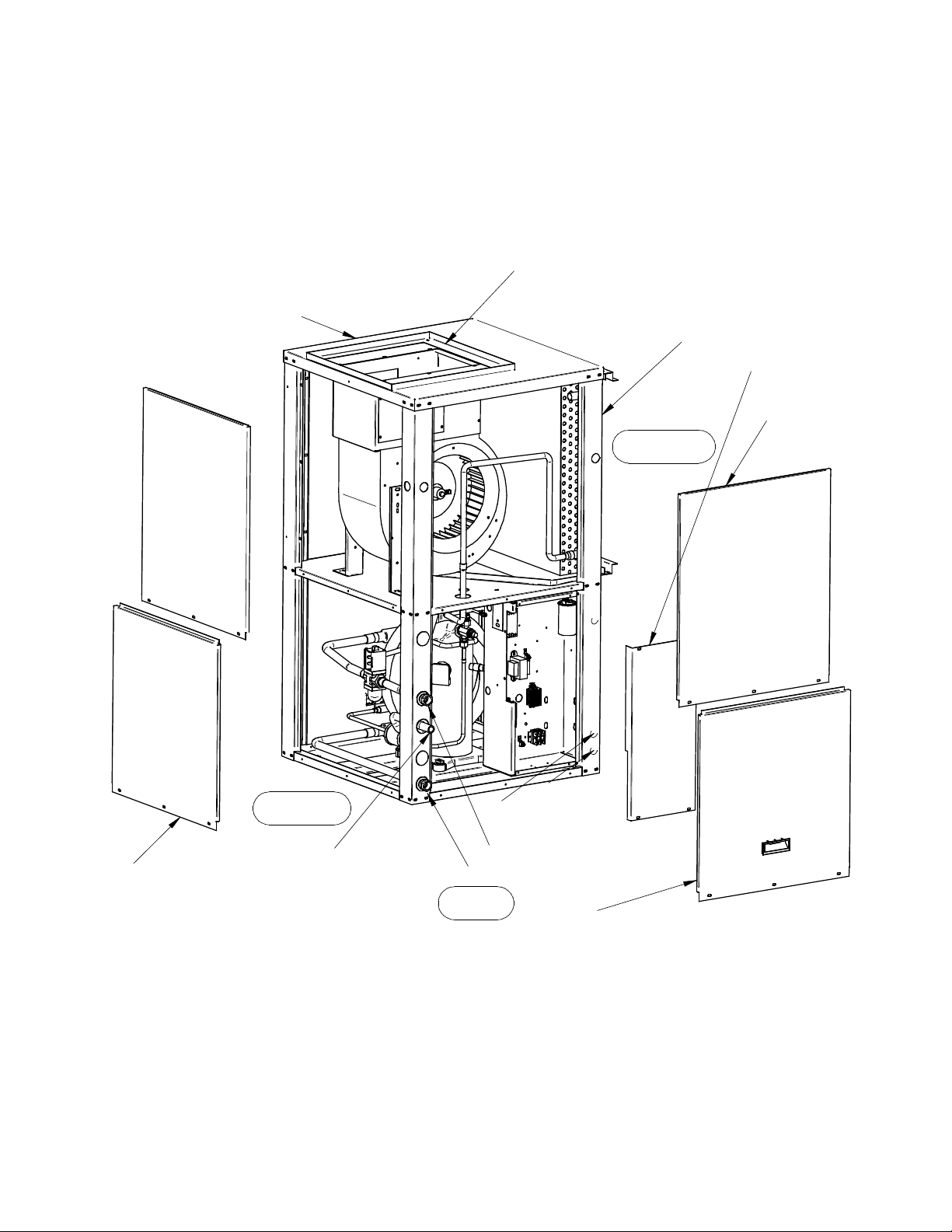
FIGURE 1
BLOWER AND MOTOR
ACCESS PANEL
SUPPLY AIR
RETURN AIR
RIGHT SIDE
ELECTRICAL
ACCESS PANEL
BLOWER
ACCESS PANEL
WATER REGULATING
ACCESS PANEL
3
LEFT SIDE
CONDENSATE
DRAIN TUBE
POWER IN
LOW VOLTAGE IN
WATER OUT
WATER IN
FRONT
ELECTRICAL AND
COMPRESSOR ACCESS PANEL
 Loading...