

Page 1
REV-1
6.1
CT / CTM / CTS / CTMS / CBT / CBTM / CTMC / TS
SECTION 6
© 2011 by Thermoplan AG, Änderungen vorbehalten
Technical manual
TROUBLESHOOTING
FOX2
Page 2
REV-1
6.2
1 X X
2 X X
3 X X
4 X X
5 X X
6 X X
7 X X
8 X X
9 X X
10 X X
11 X X
12 X X
13 X X
14 X X
15 X X
16 X X
17 X X
18 X X
19 X X
20 X X
21 X X
22 X X
23 X X
24 X X
25 X X
26 X X
27 X X
28 X X
29 X X
30 X X
31 X X
32 X X
33 X X
34 X X
35 X X
36 X X
37 X X
38 X X
39 X X
40 X X
41 X X
42 X X
43 X X
44 X X
45 X X
46 X X
47 X X
48 X X
49 X X
50 X X
51 X X
0 1 2 3 4 5 6 7 8 9 10
0 1 2 3 4 5 6 7 8 9 10
0 1 2 3 4 5 6 7 8 9 10
Page
REVISION
Page
REVISION
Page
REVISION
© 2011 by Thermoplan AG, Änderungen vorbehalten
SECTION 6
Technical manual
X Changes in content, corrections S New paging
Overview modications
Modication journal:
Revision: Data: Modication Initials:
0 2011-01-04 Basic document SO
1 2013-03-05 Various changes SO
2
3
4
5
6
7
8
9
10
Document: Troubleshooting
Page 3

REV-1
6.3
SECTION 6
© 2011 by Thermoplan AG, Änderungen vorbehalten
Technical manual
Index
1 Overview display messages ..................................................................................................................................4
2 Service menu „System Check“ ..............................................................................................................................7
2.1 Entering the service menu ...........................................................................................................................................................7
2.2 Inputs .........................................................................................................................................................................................8
2.3 Outputs ......................................................................................................................................................................................9
2.4 Touchpanel Test .........................................................................................................................................................................10
3 Touchscreen FOX .................................................................................................................................................11
3.1 Possible problems with the touchscreen .....................................................................................................................................11
3.2 Troubleshooting on touch screen................................................................................................................................................11
3.3 Overview FOX-Print ...................................................................................................................................................................12
3.4 Overview CPU ...........................................................................................................................................................................13
4 Chassis ................................................................................................................................................................14
4.1 Error messages ..........................................................................................................................................................................14
4.2 CTM Front view .........................................................................................................................................................................17
4.3 CTM Back view .........................................................................................................................................................................18
4.4 CTM Bottom view .....................................................................................................................................................................19
4.5 CTM ISO view ...........................................................................................................................................................................20
4.6 CTM ISO view 2 ........................................................................................................................................................................21
4.7 CBTM Front view .......................................................................................................................................................................22
4.8 CBTM Back view .......................................................................................................................................................................23
4.9 CBTM Bottom view ...................................................................................................................................................................24
4.10 CBTM ISO view .......................................................................................................................................................................25
4.11 CBTM ISO view 2 ....................................................................................................................................................................26
5 Mechanical module .............................................................................................................................................27
5.1 Error messages ..........................................................................................................................................................................27
5.2 Water circulation .......................................................................................................................................................................29
5.3 ISO view ...................................................................................................................................................................................30
5.4 Top view ...................................................................................................................................................................................31
5.5 Back view .................................................................................................................................................................................32
5.6 Bottom view .............................................................................................................................................................................33
5.7 ISO view Brewing unit ...............................................................................................................................................................34
5.8 Quick test .................................................................................................................................................................................35
6 Hydraulic module ................................................................................................................................................36
6.1 Error messages ..........................................................................................................................................................................36
6.2 Top view ...................................................................................................................................................................................37
6.3 Back view .................................................................................................................................................................................38
6.4 Milk way pump unit ..................................................................................................................................................................39
6.5 Water way pump unit ................................................................................................................................................................40
6.6 ISO view Pump unit ...................................................................................................................................................................41
6.7 ISO view Valve block .................................................................................................................................................................42
6.8 Quick test .................................................................................................................................................................................43
7 Brew module .......................................................................................................................................................44
1 Error messages .............................................................................................................................................................................44
2 ISO view ......................................................................................................................................................................................45
3 Back view ....................................................................................................................................................................................46
4 ISO view Sensor ...........................................................................................................................................................................47
5 ISO view Chassis ..........................................................................................................................................................................48
6 Quick test ....................................................................................................................................................................................49
8 Steam module .....................................................................................................................................................50
8.1 Error messages ..........................................................................................................................................................................50
8.2 ISO view ...................................................................................................................................................................................51
8.3 Front view .................................................................................................................................................................................52
8.4 Back view .................................................................................................................................................................................53
8.5 Quick test steam module ...........................................................................................................................................................54
Page 4
REV-1
6.4
© 2011 by Thermoplan AG, Änderungen vorbehalten
SECTION 6
Technical manual
1 Overview display messages
Error no. Text Affects module
TX0101 NTC coffeeboiler open Hydraulics (Kap. 6.1)
TX0104 Empty grounds drawer Chassis (Kap. 4.1)
TX0105 Drain tub Brew module (Kap. 7.1)
TX0106 Grounds drawer missing Chassis (Kap. 4.1)
TX0107 Bean hopper empty (left-hand side) Mechanics (Kap. 5.1)
TX0108 Service required Chassis (Kap. 4.1)
TX0109 Clean appliance Chassis (Kap. 4.1)
TX0110 Voltage low Chassis (Kap. 4.1)
TX0111 Voltage high Chassis (Kap. 4.1)
TX0113 Piston error Chassis (Kap. 4.1) / Mechanics (Kap. 5.1)
TX0114 Bean hopper empty (right-hand side) Mechanics (Kap. 5.1)
TX0115 Flow error Mechanics (Kap. 5.1) / Hydraulics (Kap. 6.1)
TX0116 Overtime error Mechanics (Kap. 5.1) / Hydraulics (Kap. 6.1)
TX0117 Change water lter Chassis (Kap. 4.1)
TX0118 Interface error Chassis (Kap. 4.1)
TX0119 Powder error Mechanics (Kap. 5.1)
TX0121 NTC steamboiler error Steam (Kap. 8.1)
TX0122 Steamboiler not ready Steam (Kap. 8.1)
TX0123 Low water level in steamboiler Steam (Kap. 8.1)
TX0124 Hot water rinse
Press rinse key
Steam (Kap. 8.1)
TX0125 Waterow error Hydraulics (Kap. 6.1)
Page 5
REV-1
6.5
SECTION 6
© 2011 by Thermoplan AG, Änderungen vorbehalten
Technical manual
1 Overview display messages
Error no. Text Affects module
TX0128 Cleaning interrupted
Open POD
Chassis (Kap. 4.1)
TX0136 Please ask for assistance Chassis (Kap. 4.1)
TX0137 Please add milk Chassis (Kap. 4.1)
TX0138 Steamboiler ll error Steam (Kap. 8.1)
TX0139 Bean hopper missing or command unit open Chassis (Kap. 4.1) / Mechanics (Kap. 5.1)
TX0141 NTC coffee boiler short-circuit Hydraulics (Kap. 6.1)
TX0143 Machine locked
Start cleaning
Chassis (Kap. 4.1)
TX0145 Add coffee beans
Press ok to proceed product dispensing
Mechanics (Kap. 5.1)
TX0146 Press stop key Chassis (Kap. 4.1)
TX0149 Insert coffe pad Chassis (Kap. 4.1)
TX0150 Remove cleaning tablets Chassis (Kap. 4.1)
TX0151 No waterow detected Hydraulics (Kap. 6.1)
TX0153 Cleaning done
Standby
Chassis (Kap. 4.1)
TX0154 Milk pump: no pulse Hydraulics (Kap. 6.1)
TX0155 Water pump: no pulse Hydraulics (Kap. 6.1)
TX0161 Please wait Hydraulics (Kap. 6.1)
TX0162 Error grinder right-hand side Mechanics (Kap. 5.1)
TX0163 Error grinder left-hand side Mechanics (Kap. 5.1)
TX0164 Cleaning interrupted
Please press rinse key
Chassis (Kap. 4.1)
TX0167 Cleaning interrupted
Remove grounds drawer
Chassis (Kap. 4.1)
TX0174 Remove and empty grounds drawer Chassis (Kap. 4.1)
Page 6

REV-1
6.6
© 2011 by Thermoplan AG, Änderungen vorbehalten
SECTION 6
Technical manual
Error no. Text Affects module
TX0188 Check milk temperature Chassis (Kap. 4.1)
TX0201 Cold start rinse
Please press rinse key
Chassis (Kap. 4.1) / Hydraulics (Kap. 6.1)
TX0241 Machine rinsing
ATTENTION HOT!
Chassis (Kap. 4.1)
1 Overview display messages
Page 7
REV-1
6.7
SECTION 6
© 2011 by Thermoplan AG, Änderungen vorbehalten
Technical manual
2. Service menu „System Check“
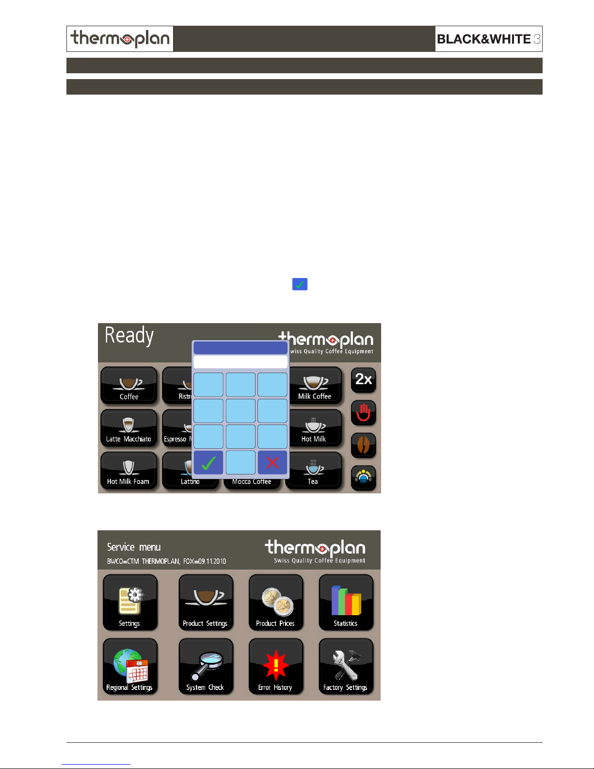
2.1 Entering the service menu
To enter the different service levels, follow these steps:
1. Push and hold left top corner.
2. The „Enter PIN“ window appears. Enter code and conrm with
.
The service menu can always be left by pressing the top left corner of the display.
23
1
56
4
89
7
Enter PIN
******
3. Following screen appears:
There are two different codes which each provide another programming level in the software:
User level: Code 111111
In the user level only few settings like product parameters, datetime and language can be set.
Technician level: Code 137900
In the technician level all settings can be looked-up and set.
Page 8
REV-1
6.8
© 2011 by Thermoplan AG, Änderungen vorbehalten
SECTION 6
Technical manual
Parameter Description
Status
NormalbetriebCTCTM
CTS
CTMS
CBT
CBTM
Boiler temperature
Shows the temperature of coffee boiler
91 °C
x x x x x x
Pot temperature
Shows the temperature of coffee brewer
50 °C
x x
Ground Drawer
detected
Remove grounds drawer to check the contact.
If a
is shown, insert the grounds drawer correctly.
x x x x x x
Flowmeter ticks/sec
The value (ticks) must not change in the system check menu. If the value changes, it
means that the owmeter turns without the machine running -> there is a leakage in the
area right after the owmeter.
0
x x x x x x
Brewing motor in
endposition
Shows if the brew chamber on the mechanical module is in it‘s starting position
(touches the end switch).
x x x x x x
Motorrotation
detected
Turn the spindle wheel of the brew chambre slowly manually to check the 24VDC
motor. The value should alternate between
and .
x x x x x x
Beanhopper &
panel ok
Remove bean hopper or move up the control panel to check the signal.
x x x x x x
Pot level
Shows current ll state in % of the full coffee brewer tank‘s capacity.
20%
x x
Pot level step
Shows the current level of the coffee brewer‘s tank.
0
x x
Milkcleaningkey
Remove cleaning key to check the contact.
x x x x x x
Milkcleaningtablet
Remove cleaning key and press the contact pin inside the cleaning key‘s housing to
check the contact.
x x x x x x
1.1 Inputs
2.2 Inputs
2. Service menu „System Check“
Page 9
REV-1
6.9
SECTION 6
© 2011 by Thermoplan AG, Änderungen vorbehalten
Technical manual
Press the output you wish to check to start it‘s function. For example press on „Grinder 1“ so the left grinder starts to
move. Press a valve to open it.
Following outputs can be checked:
Parameter Description
CT
CTM
CTS
CTMS
CBT
CBTM
Grinder 1
Function check: Grinder motor (230V). The rotation of the motor is in direction of the left
grinder which will grind coffee. If the grinder should be blocked, use the parameter
„Grinder 2“ so that grinder 1 turns in the opposite direction.
x x x x x x
Grinder 2
Function check: Grinder motor (230V). The rotation of the motor is in direction of the right
grinder which will grind coffee. If the grinder should be blocked, use the parameter
„Grinder 1“ so that grinder 2 turns in the opposite direction.
x x x x x x
Coffeeheater
Coffee boiler is heating. Attention: The heater is not secured against overheating!
x x x x x x
Coffeepump
Water pump starts. Attention: Only press shortly because the valves are closed and the
pump is heating up!
x x x
Milkpump
Milk pump starts.
x x x
Potpump
Tank pump starts. Attention: Only press shortly because the valves are closed and the pump
is heating up.
x x
Potheater
Tank is heating. Attention: Heater is not secured against overheating!
x x
Brewvalve
Brew valve on valve block opens (you should hear a „click“ noise)
x x x x x x
Bypassvalve
Bypass valve on valve block opens (you should hear a „click“ noise)
x x x x x x
Teavalve
Tea valve on valve block opens (you should hear a „click“ noise)
x x x x x x
Milkdrainvalve
Milk drain valve on valve block opens (you should hear a „click“ noise)
x x x
Milkselectvalve
Milk selection valve on valve block opens (you should hear a „click“ noise)
x x x
Milkdraingatevalve
Milk drain gate valve on valve block opens (you should hear a „click“ noise)
x x x
Milkairvalve
Milk air valve on valve block opens (you should hear a „click“ noise)
x x x
Milkrinsevalve
Milk rinse valve on valve block opens (you should hear a „click“ noise)
x x x
Milkcleanvalve
Milk clean valve on valve block opens (you should hear a „click“ noise)
x x x
Coldmilkvalve
Cold milk valve on valve block opens (you should hear a „click“ noise)
x x x
Refrigeratorrinsevalve
Refrigerator rinse valve on valve block opens (you should hear a „click“ noise)
x x x
POD/Cleaningvalve
Cleaning valve on valve block opens (you should hear a „click“ noise)
x x x x x x
Potvalve
Tank valve on valve block opens (you should hear a „click“ noise)
x x
Coffeeoutletvalve
Coffee outlet valve on valve block opens (you should hear a „click“ noise)
x x
Tankdrainvalve
Tank drain valve on valve block opens (you should hear a „click“ noise)
x x
2.3 Outputs
2. Service menu „System Check“
Page 10

REV-1
6.10
© 2011 by Thermoplan AG, Änderungen vorbehalten
SECTION 6
Technical manual
To leave the test screen, press for 2 seconds
on any place on the touchscreen.
The system check menu also contains an option to check the touchscreen for it‘s functionality. Press on „Touchpanel test“
to start the test program. A grid will appear on the screen. After every touch on the screen a red „dot“ should appear on
the same spot.
2.4 Touchpanel Test
2. Service menu „System Check“
Zum Verlassen Touch 2s berühren
to leave, press and hold for 2s
Page 11

REV-1
6.11
SECTION 6
© 2011 by Thermoplan AG, Änderungen vorbehalten
Technical manual
3.1 Possible problems with the touchscreen
3. Touchscreen FOX
3.2 Troubleshooting on touch screen
• Slow reaction of the touchscreen
• Screen is ickering
• Some product buttons have disappeared
• Display shows unreadable hieroglyphics instead of text
• Machine does not start completely: „Ready“ is not displayed
• Blue box with error message on left top corner of the screen
• Screen stays black
• White screen (screen only returns white light)
Follow these instructions step by step to determine the error the fastest way.
Requirement: The CF card must be formatted with FAT or FAT32!
NTFS data system does not work!
Step 1
• Switch off machine
• Wait for 10 seconds
• Switch machine back on
• If this action does not solve the problem, proceed with step 2
Step 2
• Switch off machine
• Remove CF card (position CF card can be seen in section „3.3 Overview FOX-Print“)
• Check if there are any defects on the pins in the CF card slot
• Reinsert the CF card
• Switch machine back on
• If this action does not solve the problem, proceed with step 3
Step 3
Check FOX-Print index (see section „3.3 Overview FOX-Print“)
• Recommendation of CF card for FOX 70-Print version A-C: CF card type „take MS“
• From FOX 70-Print version D the CF card type does not matter anymore
• If this action does not solve the problem, proceed with step 4
Page 12

REV-1
6.12
© 2011 by Thermoplan AG, Änderungen vorbehalten
SECTION 6
Technical manual
3.2 Troubleshooting on touch screen
3. Touchscreen FOX
Step 4
Perform a touch panel test in the service menu „System Check“ to check the reaction time
Zum Verlassen Touch 2s berühren
to leave, press and hold for 2s
Step 5
Communication control CPU <--> FOX-Print by LEDs.
LEDs must be blinking on both CPU and FOX-Print!
If the LEDs do not blink (LEDs are marked in section „3.3 Overview FOX-Print“ and „3.4 Overview CPU“), but are out
of action or glow permanently, follow these steps:
• Switch off machine
• Plug out connection cable (see section „3.3 Overview FOX-Print“ and „3.4 Overview CPU“)
CAUTION: The machine must be turned off at the main switch before plugging the connection cable in or out. Else
there can be discharges on the electronincs, which can cause errors like in section „3.1 Possible problems with the
touchscreen“.
• Control the contacts on both: CPU and FOX-Print
• Plug connection cable back in
• Switch machine back on and check LEDs
• If there is still no connection repeat this step using a new connection cable
• If this action does not solve the problem, proceed with step 6
Step 6
• Switch off machine
• Change the FOX-Print
• Reconnect all cables and switch machine back on
• If this action does not solve the problem, proceed with step 7
Step 7
• Switch off machine
• Change the CPU
• Reconnect all cables and switch machine back on
Page 13
REV-1
6.13
SECTION 6
© 2011 by Thermoplan AG, Änderungen vorbehalten
Technical manual
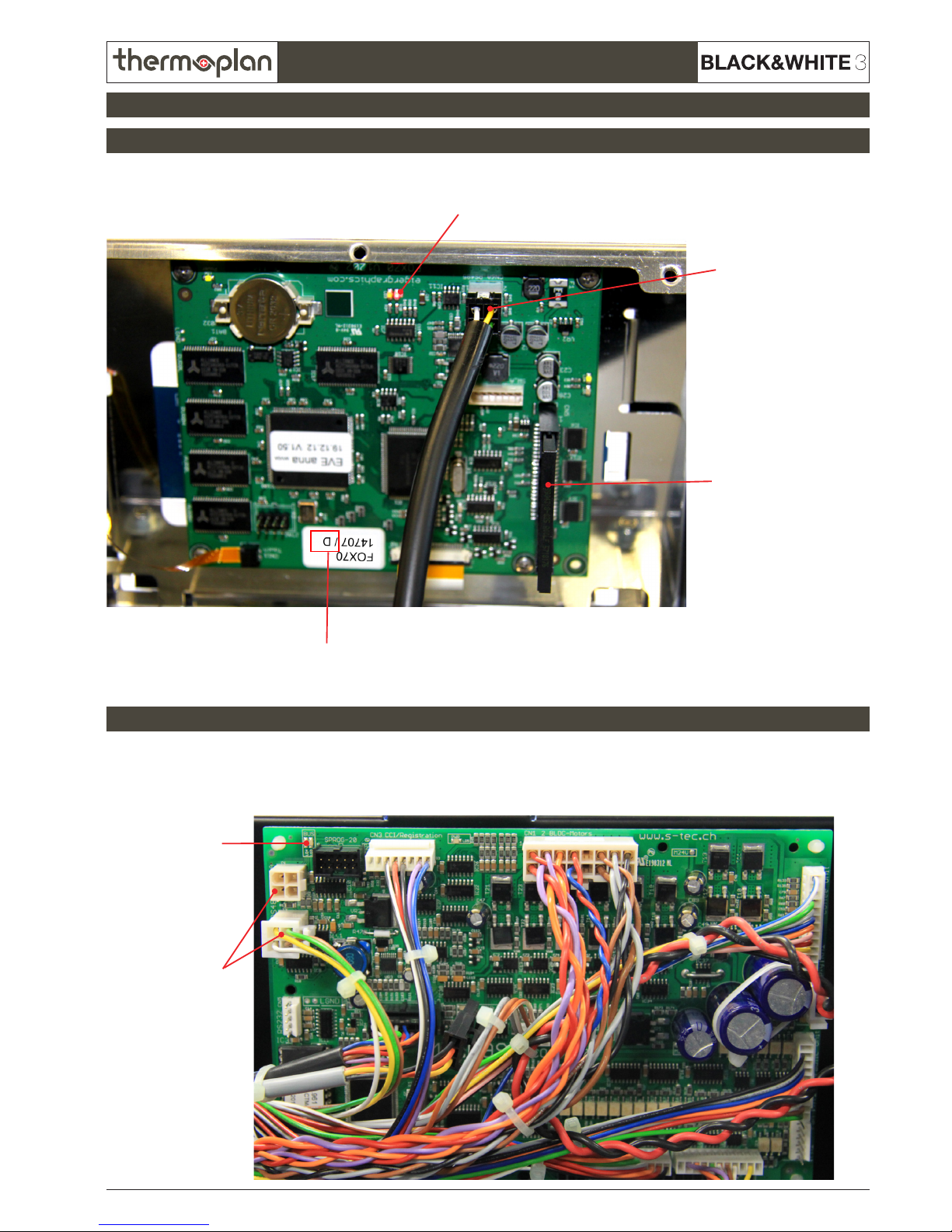
3.3 Overview FOX-Print
3.4 Overview CPU
3. Touchscreen FOX
Connection-LED CPU (blinking = connection OK)
The FOX-Print is located on the back of the touchscreen.
The CPU is located on the back of the chassis (see particular chassis ISO views).
Connection-
cable CPU - FOXPrint + slot
CF card in slot
FOX-Print index
Connection-LED
FOX-Print
(blinking =
connection OK)
Connection-
cable CPU -
FOX-Print slot
Page 14
REV-1
6.14
© 2011 by Thermoplan AG, Änderungen vorbehalten
SECTION 6
Technical manual
4.1 Error messages Chassis
4. Chassis
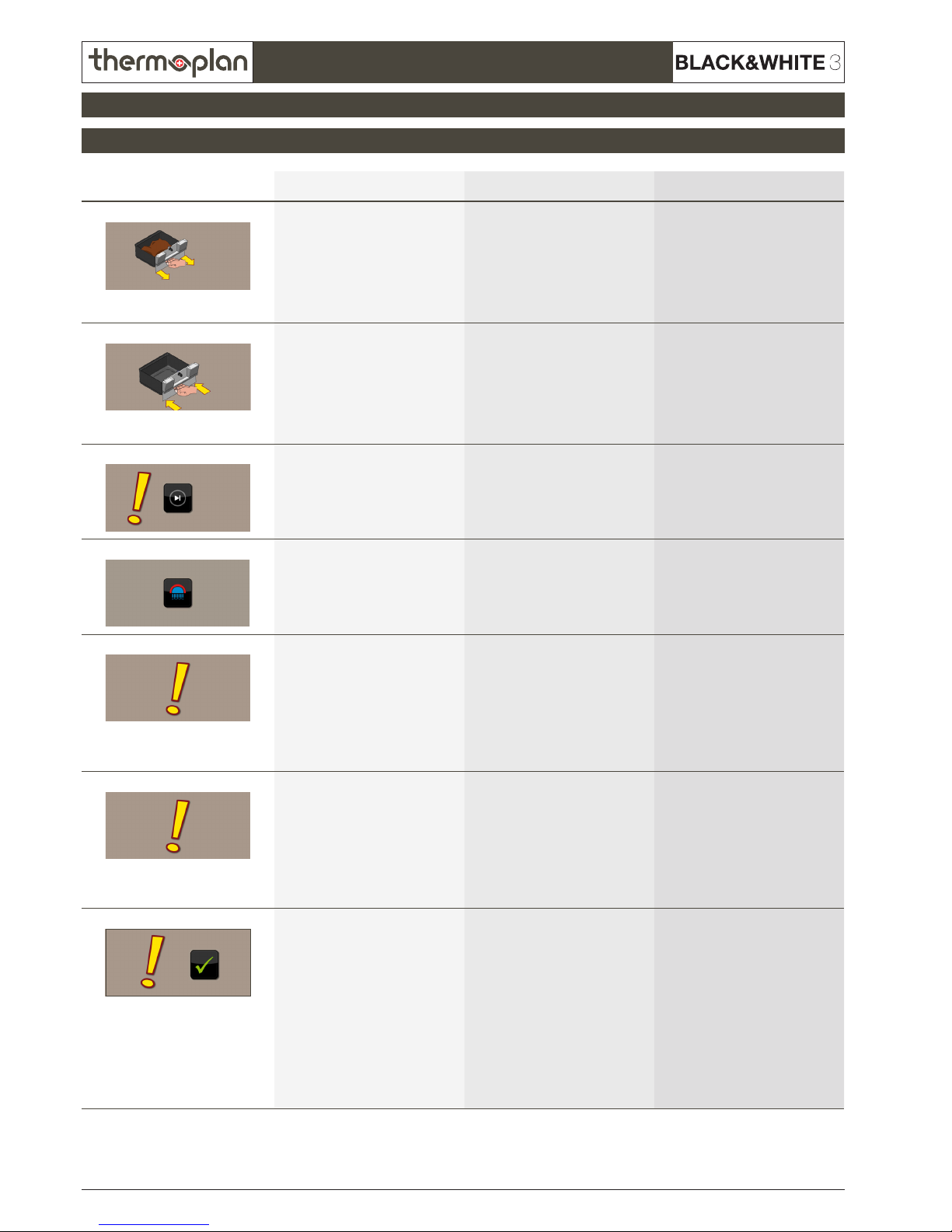
Error no. / picture Text Cause Fix
TX0104 Empty grounds drawer - Grounds drawer full
- No magnet on grounds drawer
- Magnet switch on chassis
defective
- Cable between magnet switch and
CPU has short circuit
- Remove grounds drawer, empty,
reinsert (wait min. 5 seconds)
- Mount magnet again
- Replace magnet switch
- Check cable and replace if
necessary
TX0106
Grounds drawer missing - Grounds drawer not inserted
correctly
- No magnet on grounds drawer
- Magnet switch on chassis
defective
- Cable between magnet switch and
CPU has short circuit
- Remove grounds drawer, empty,
reinsert (wait min. 5 seconds)
- Mount magnet again
- Replace magnet switch
- Check cable and replace if
necessary
TX0108
Service required Amount of brew cycles programmed
into machine has been reached
Provide annual service on machine.
Reset counter in service menu „Statistics“, to delete message. Machine
starts counter again from 0.
TX0109
Clean appliance Since the rst product dispensing
48 hours have passed (coffee products only) or 24 hours have passed
(if milk products were dispensed).
Machine must be cleaned to unlock.
Clean machine
TX0110
Voltage low Voltage too low, operation is
stopped as soon as voltage is below
the set tolerance (adjustable from
0-30%).
If the voltage gets too low during
a product dispensing, the product
will be nished, then the operation
stops.
Wait until voltage stabilises
TX0111
Voltage high Voltage too high, operation is
stopped as soon as voltage is above
the set tolerance (adjustable from
0-30%).
If the voltage gets too high during
a product dispensing, the product
will be nished, then the operation
stops.
Wait until voltage stabilises
TX0113
Piston error - Brew cylinder cannot travel to
desired position
- The gear belt between motor and
drive screw of the brew cylinder
is defective or not mounted
- The way of the brew cylinder is
blocked
- The mobile piston is blocked and
the brew cylinder cannot travel
back to the micro switch
- The brew cylinder cannot travel
over the x piston.
- Try dispensing product again
- Perform a rinse
- Check mechanical module
- gear belt
- brew cylinder
- mobile piston
- micro switch
- x piston
Page 15
REV-1
6.15
SECTION 6
© 2011 by Thermoplan AG, Änderungen vorbehalten
Technical manual
Chassis
4.1 Error messages Chassis
4. Chassis
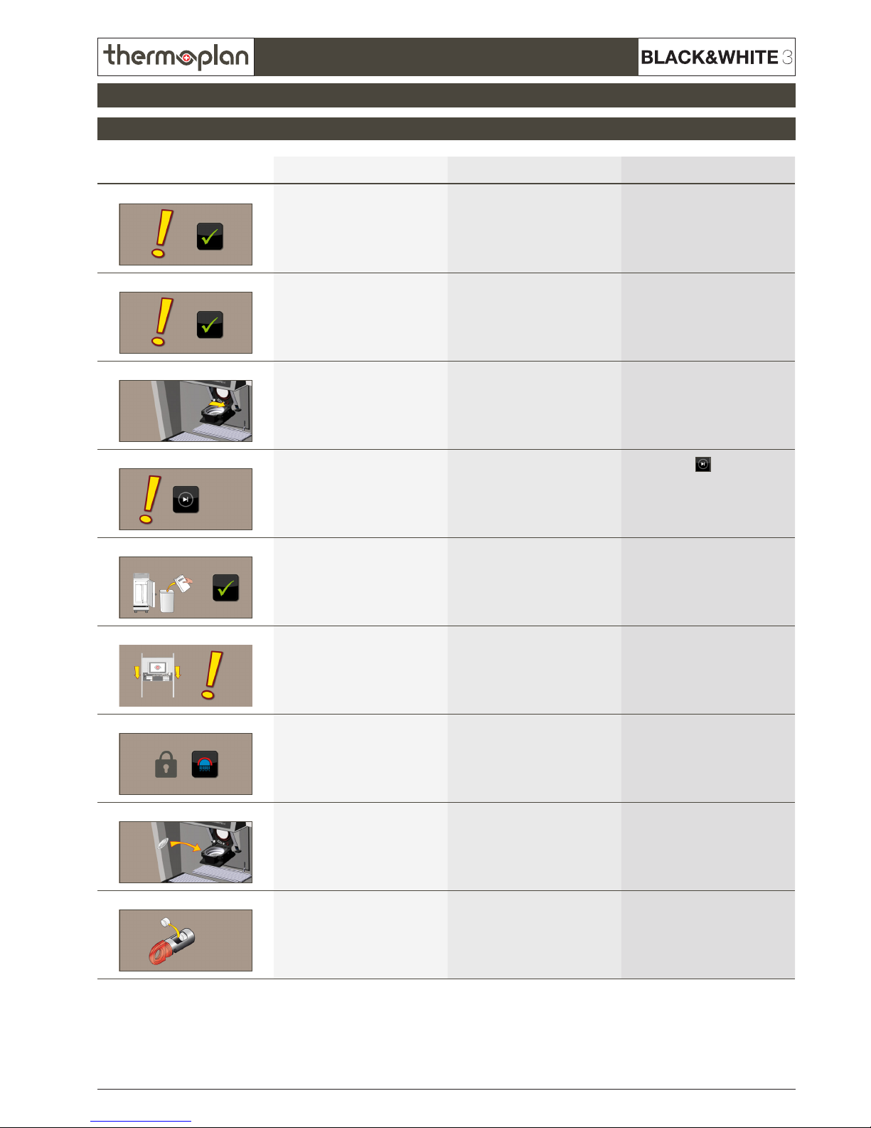
Error no. / picture Text Cause Fix
TX0117 Change water lter Pre-set amount of water has own
through water lter
Change water lter, then reset
counter in service menu.
TX0118
Interface error „Interface“ is activated in software:
- Wrong payment interface
- No payment interface connected
Check interface settings in service
menu. If no interface is connected,
switch option to „off“
TX0131
Cleaning interrupted
Open POD
Cleaning switch on POD on wrong
side
Change POD‘s switch to product
mode
TX0136
Please ask for assistance Only shows up in self-service mode
so consumers do not try to x the
problem themselves.
Press and hold
until actual
display message shows up.
Follow orders or look the actual
message up in error list for further
information.
TX0137
Please add milk Milk is empty 1. Rell milk
2. Check level sensor
TX0139
Bean hopper missing or command
unit open
Bean hopper is not mounted or the
command desk is open
1. Place bean hopper correctly
2. Close command desk
3. Check contacts
TX0143
Machine locked
Start cleaning
Cleaning has not been performed.
Machine is locked until cleaning is
done.
Clean machine
TX0149
Insert coffe pad Coffee machine preparing for
dispensing a POD product
Open POD, insert coffee pod, close
POD
TX0150
Remove cleaning tablets Cleaning tablets are in cleaning key
when cleaning not in progress
Remove cleaning tablets from cleaning key. They must only be inserted
during cleaning.
Page 16
REV-1
6.16
© 2011 by Thermoplan AG, Änderungen vorbehalten
SECTION 6
Technical manual
4.1 Error messages Chassis
4. Chassis
Error no. / picture Text Cause Fix
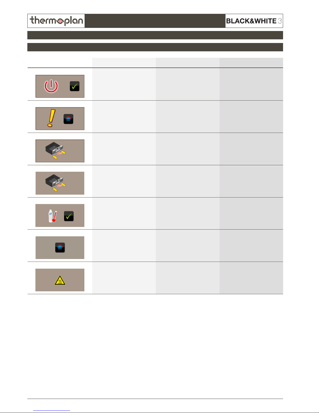
TX0153 Cleaning done
Standby
After daily cleaning, the machine
changes to standby mode
Press OK to get the machine back
from standby.
TX0164
Cleaning interrupted
Please press rinse key
Cleaning has been interrupted Press rinse key to restart cleaning
procedure
TX0167
Cleaning interrupted
Remove grounds drawer
Cleaning has been interrupted Remove and reinsert grounds
drawer
TX0174
Remove and empty grounds drawer Grounds drawer has to be removed
for next action
Remove grounds drawer
TX0188
Check milk temperature Milk temperature too high 1. Check milk temperature
2. Switch on refrigerator
3. Check temperature sensors
TX0201
Cold start rinse
Please press rinse key
Rinse for start- and warm-up of
machine
Press rinse key
TX0241
Machine rinsing
ATTENTION HOT!
Warning note during rinse Wait until rinse has nished
Page 17
REV-1
6.17
SECTION 6
© 2011 by Thermoplan AG, Änderungen vorbehalten
Technical manual
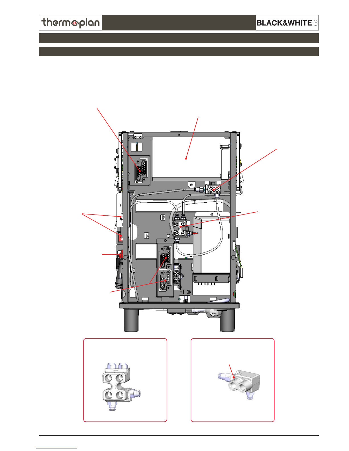
Hydraulic clip
Cleaning
Cleaning
Check valveTea
Brew
Brew
(not used)
Mechanical clip
Cleaning key
Connection mechanical module
Hydraulic clip
Mechanical clip
Main switches
CPU
Connections
hydraulic module
4.2 CTM Front view
4. Chassis
Page 18

REV-1
6.18
© 2011 by Thermoplan AG, Änderungen vorbehalten
SECTION 6
Technical manual
Connections hydraulic moduleNet clips
Connectioin mechanical module
4.3 CTM Back view
4. Chassis
Page 19

REV-1
6.19
SECTION 6
© 2011 by Thermoplan AG, Änderungen vorbehalten
Technical manual
Flooding area
Flooding sensors
Drain Main water connection
4.4 CTM Bottom view
4. Chassis
Page 20

REV-1
6.20
© 2011 by Thermoplan AG, Änderungen vorbehalten
SECTION 6
Technical manual
Main switch
Cleaning key
CPU
4.5 CTM ISO view
4. Chassis
Page 21

REV-1
6.21
SECTION 6
© 2011 by Thermoplan AG, Änderungen vorbehalten
Technical manual
Cleaning key
Power print
(Powerboard)
Milk valve Drain gate valve
4.6 CTM ISO view 2
4. Chassis
Page 22

REV-1
6.22
© 2011 by Thermoplan AG, Änderungen vorbehalten
SECTION 6
Technical manual
Connection
Hydraulic module
Main switch
Hydraulic clip
Hydraulic clip
Cleaning
Cleaning
Check valveTea
Brew
Brew
(not used)
Hydraulic clip
Cleaning
key
Connection
Brew module
Connection mechanical module
CPU Mechanical clip
4.7 CBTM Front view
4. Chassis
Page 23

REV-1
6.23
SECTION 6
© 2011 by Thermoplan AG, Änderungen vorbehalten
Technical manual
Connection hydraulic moduleNet clips
Connection
brew module
Connection mechanical module
4.8 CBTM Back view
4. Chassis
Page 24

REV-1
6.24
© 2011 by Thermoplan AG, Änderungen vorbehalten
SECTION 6
Technical manual
Flooding area
Flooding sensors
Check valve Main water connection
4.9 CBTM Bottom view
4. Chassis
Page 25

REV-1
6.25
SECTION 6
© 2011 by Thermoplan AG, Änderungen vorbehalten
Technical manual
Main switches
Cleaning key
CPU
4.10 CBTM ISO view
4. Chassis
Page 26

REV-1
6.26
© 2011 by Thermoplan AG, Änderungen vorbehalten
SECTION 6
Technical manual
Cleaning key
Powerprint
(Powerboard)
Milk valve Drain gate valve
4.11 CBTM ISO view 2
4. Chassis
Page 27

REV-1
6.27
SECTION 6
© 2011 by Thermoplan AG, Änderungen vorbehalten
Technical manual
5.1 Error messages mechanical module
5 Mechanical module
Error no. / picture Text Cause Fix
TX0107 Bean hopper empty (left-hand side) - Bean hopper left is empty
- Lock of bean hopper is closed /
not connected
- After grinding, the brew cylinder
moves completely over the x
piston (like in rinse).
- Grinder motor or starting
condenser is defective
- Grinder motor triac on power print
is defective.
- Rell coffee beans in left bean
hopper
- Check grinding position and
powder way
- Check if coffee beans are
grinded
- Check cable connections between
mechanical module - power print
and CPU.
- Check gear belt, gear belt plates
and voltage
TX0113
Piston error - Brew cylinder cannot travel to
desired position
- The gear belt between motor and
drive screw of the brew cylinder
is defective or not mounted
- The way of the brew cylinder is
blocked
- The mobile piston is blocked and
the brew cylinder cannot travel
back to the micro switch
- The brew cylinder cannot travel
over the x piston.
- Try dispensing product again
- Perform a rinse
- Check mechanical module
- gear belt
- brew cylinder
- mobile piston
- micro switch
- x piston
TX0114
Bean hopper empty (right-hand
side)
- Bean hopper right is empty
- Lock of bean hopper is closed /
not connected
- After grinding, the brew cylinder
moves completely over the x
piston (like in rinse).
- Grinder motor or starting
condenser is defective
- Grinder motor triac on power print
is defective.
- Rell coffee beans in right bean
hopper
- Check grinding position and
powder way
- Check if coffee beans are
grinded
- Check cable connections between
mechanical module - power print
and CPU.
- Check gear belt, gear belt plates
and voltage
TX0115
Flow error Too low water ow 1. Open mains water connection
2. Empty grounds drawer
3. Perform rinse
4. Check owmeter
5. Check pump
TX0116
Overtime error Product is not dispensed correctly
because of too low water ow
1. Dispense product again
2. Check owmeter
3. Check pump
TX0119
Powder error Grinders blocked 1. Empty grounds drawer +
vacuum-clean grinders
2. Perform rinse
3. Check mechanical module
TX0139
Bean hopper missing or command
unit open
Bean hopper is not mounted or the
command desk is open
1. Place bean hopper correctly
2. Close command desk
3. Check contacts
Page 28

REV-1
6.28
© 2011 by Thermoplan AG, Änderungen vorbehalten
SECTION 6
Technical manual
5.1 Error messages mechanical module
5 Mechanical module
Error no. / picture Text Cause Fix
TX0145 Add coffee beans
Press ok to proceed product
dispensing
Run out of beans during product
dispensing
Rell beans and conrm with OK
button
TX0162
Error grinder right-hand side Grinder error right-hand side 1. Empty grounds drawer +
vacuum-clean grinders
2. Perform rinse
3. Check mechanical module
TX0163
Error grinder left-hand side Grinder error left-hand side 1. Empty grounds drawer +
vacuum-clean grinders
2. Perform rinse
3. Check mechanical module
Page 29

REV-1
6.29
SECTION 6
© 2011 by Thermoplan AG, Änderungen vorbehalten
Technical manual
Brew cycle
Rinse cycle
Cleaning cycle
Every second cycle also runs through the brew valve!
Hot water from coffee boiler
Connector for mec. module
Teon pipe to brew chamber
Brew chamber over mobile piston
Through grinded coffee
Through x piston
Coffee outlet
Brew valve
Hot water from coffee boiler
Brew valve
Connector for mec. module
Teon pipe to brew chamber
Through x piston
Brew chamber over mobile piston
Coffee outlet
Hot water from coffee boiler (through cleaning key)
Connector for mec. module
Teon pipe to brew chamber
Through x piston
Brew chamber over mobile piston
Coffee outlet
5.2 Water circulation
5 Mechanical module
Page 30

REV-1
6.30
© 2011 by Thermoplan AG, Änderungen vorbehalten
SECTION 6
Technical manual
Grinder right
Brew chamber motor
Grinder left
Grinder motor
Brew chamber
Coffee outlet
Connection
Gear belt
Brew chamber drive
Coffee
outlet valve
5.3 ISO view
5 Mechanical module
Page 31

REV-1
6.31
SECTION 6
© 2011 by Thermoplan AG, Änderungen vorbehalten
Technical manual
Gear
Gear belt
Brew chamber drive
Connection
mechanical module
Connection
cleaning
Brew chamber motor
Grinder right
Grinder left
Coarsness setting Coarsness setting
Grinder motor
Brew chamber
ne necoarse coarse
Spindle
5.4 Top view
5 Mechanical module
Page 32

REV-1
6.32
© 2011 by Thermoplan AG, Änderungen vorbehalten
SECTION 6
Technical manual
GearConnection
cleaning
Gear belt
Grinder drive
Connection
mechanical module
Gear belt
Brew chamber drive
Grinder motor
5.5 Back view
5 Mechanical module
Page 33

REV-1
6.33
SECTION 6
© 2011 by Thermoplan AG, Änderungen vorbehalten
Technical manual
Connection
cleaning
Connection
mechanical module
Gear belt
Grinder drive
5.6 Bottom view
5 Mechanical module
Page 34

REV-1
6.34
© 2011 by Thermoplan AG, Änderungen vorbehalten
SECTION 6
Technical manual
Brew chamber
Spindle
Backmost
bearing block
Front
bearing block
Brew chamber motor
Fix piston
5.7 ISO view Brewing unit
5 Mechanical module
Page 35

REV-1
6.35
SECTION 6
© 2011 by Thermoplan AG, Änderungen vorbehalten
Technical manual
Rapid test mechanical module
Connection settings:
1 Brew motor 24VDC+ 8
not set
15
not set
22 L1 (Grinder motor, heaters)
2 Brew motor 24VDC- 9
not set
16
not set
23
not set
3 Brew motor 5VDC+ 10
not set
17
not set
24 N Grinder 1
4
GND micro switch, brew motor 11 Reed bean hopper 2 18
not set
25 N Grinder 2
5 Signal brew motor 12
24VDC+ (reed, valve) 19
not set
6 Micro switch 5VDC 13 Coffee outlet valve 20 Grounding
7
not set
14
not set
21 Heater N
1
20
25
6
5.8 Quick test
5 Mechanical module
Page 36

REV-1
6.36
© 2011 by Thermoplan AG, Änderungen vorbehalten
SECTION 6
Technical manual
6.1 Error messages Hydraulic module
6 Hydraulic module
Error no. / picture Text Cause Fix
TX0101 NTC coffeeboiler open Problem with NTC in coffee boiler Check NTC and if necessary
exchange
TX0115
Flow error Too low water ow 1. Open mains water connection
2. Empty grounds drawer
3. Perform rinse
4. Check owmeter
5. Check pump
TX0116
Overtime error Product is not dispensed correctly
because of too low water ow
1. Dispense product again
2. Check owmeter
3. Check pump
TX0125
Waterow error No water pressure or owmeter
defective
1. Open mains water connection
2. Empty grounds drawer
3. Perform rinse
4. Check owmeter
5. Check pump
TX0141
NTC coffee boiler short-circuit NTC on coffee boiler had a short
circuit
Change NTC on coffee boiler
TX0151
No waterow detected No water pressure or owmeter
defective
1. Open mains water connection
2. Empty grounds drawer
3. Perform rinse
4. Check owmeter
5. Check pump
TX0154
Milk pump: no pulse Milk pump not recognised
TX0155
Water pump: no pulse Milk pump not recognised
TX0161
Please wait Machine rinses Wait until rinse is nished
TX0201
Cold start rinse
Please press rinse key
Rinse for start- and warm-up of
machine
Press rinse key
Page 37

REV-1
6.37
SECTION 6
© 2011 by Thermoplan AG, Änderungen vorbehalten
Technical manual
Flowmeter
Cleaning
connection
Connection
hydraluic module
Tea
connection
Air regulator
warm
Air regulator
cold
Heater cutout
(after over-
heating press
middle button
in again)
Tea valve
Milk outlet
Overpressure
/ Drain
Hot water boiler Heater cutout
(after overheating press middle button in again)
Cleaning
valve
6.2 Top view Hydraulic module
6 Hydraulic module
Page 38

REV-1
6.38
© 2011 by Thermoplan AG, Änderungen vorbehalten
SECTION 6
Technical manual
Air valve
Tea valve
Connections
Hydraulic module
Flowmeter
Hot water boiler
Overpressure valve
Brew valve
Tea connection
Cleaning
connection
Brew
connection
Pump unit
NTC coffee boiler
6.3 Back view
6 Hydraulic module
Page 39

REV-1
6.39
SECTION 6
© 2011 by Thermoplan AG, Änderungen vorbehalten
Technical manual
Milk way / Cleaning way
Rinse way
6.4 Milk way pump unit
6 Hydraulic module
Page 40

REV-1
6.40
© 2011 by Thermoplan AG, Änderungen vorbehalten
SECTION 6
Technical manual
Water way
Cleaning way
6.5 Water way pump unit
6 Hydraulic module
Page 41

REV-1
6.41
SECTION 6
© 2011 by Thermoplan AG, Änderungen vorbehalten
Technical manual
Water pump
Clean valve
Rinse valve
Milk nozzle
Milk pump
Air valve
Rinse valve: Needed to rinse the milk system after every milk product dispensing.
Clean valve: Needed to clean the complete system.
Air valve: Needed to add air to the milk for producing milk froth.
Connection
to owmeter
Connection
from milk clip
Connection
to boiler
6.6 ISO view Pump unit
6 Hydraulic module
Page 42

REV-1
6.42
© 2011 by Thermoplan AG, Änderungen vorbehalten
SECTION 6
Technical manual
Tea valve
Cleaning valve
Brew valve
Cleaning
connection
Tea
connection
Brew
connection
6.7 ISO view Valve block
6 Hydraulic module
Page 43

REV-1
6.43
SECTION 6
© 2011 by Thermoplan AG, Änderungen vorbehalten
Technical manual
Rapid test hydraulic module
Connection settings 1:
1 Brew valve 8
not set
15 GND Flowmeter 22 Motor water pump hall C
2 Tea valve 9 Air selection valve / cold milk valve 16
not set
23 Motor milk pump hall A
3 Cleaning valve 10 24VDC+ Valves pump unit 17
not set
24 Motor milk pump hall B
4
not set
11 Milk clean valve 18 Signal Flowmeter 25 Motor milk pump hall C
5 Milk air valve 12 Pump motors 24VDC+ 19 Signal NTC coffee boiler
6 Milk rinse valve 13 Pump motors 24VDC- 20 Motor water pump hall A
7 Air selection valve / cold milk valve 14 NTC coffee boiler / flowmeter 5VDC+ 21 Motor water pump hall B
Connection settings 2:
1
not set
7 Motor water pump coil A A Heater N
2
not set
8 Motor water pump coil B B Heater L
3
not set
9 Motor water pump coil C C Grounding
4
not set
10 Motor milk pump coil A
5
not set
11 Motor milk pump coil B
6
not set
12 Motor milk pump coil C
1
1
A
B
C
3
6
25
Connection 1
Connection 2
20
6.8 Quick test
6 Hydraulic module
Page 44

REV-1
6.44
© 2011 by Thermoplan AG, Änderungen vorbehalten
SECTION 6
Technical manual
7.1 Error messages brew module
7 Brew module
Error no. / picture Text Cause Fix
TX0105 Drain tub - Leckage on mechanical or
hydraulic module.
- Short circuit on tub sensors in
chassis.
- Short circuit on cable between tub
sensors and CPU.
- Check mechanical and hydraulic
module
- Check tub sensors and replace if
necessary
- Check cable and replace if
necessary
Page 45

REV-1
6.45
SECTION 6
© 2011 by Thermoplan AG, Änderungen vorbehalten
Technical manual
Brew Tank
Sensor unit
7.2 ISO view
7 Brew module
Page 46

REV-1
6.46
© 2011 by Thermoplan AG, Änderungen vorbehalten
SECTION 6
Technical manual
Connection
brew tank
Brew tank
7.3 Ruckansicht
7 Brew module
Page 47

REV-1
6.47
SECTION 6
© 2011 by Thermoplan AG, Änderungen vorbehalten
Technical manual
7.4 ISO view Sensor
7 Brew module
Page 48

REV-1
6.48
© 2011 by Thermoplan AG, Änderungen vorbehalten
SECTION 6
Technical manual
Pump
Jug valve
Tank drain valve
7.5 ISO view Chassis
7 Brew module
Page 49

REV-1
6.49
SECTION 6
© 2011 by Thermoplan AG, Änderungen vorbehalten
Technical manual
Rapid test brew module
Connection settings:
1
NTC coffee tank 5VDC+ 8 Print pressure sensor 15
not set
22 Triac A2
2
NTC coffee tank signal 9
not set
16
not set
23 Triac G
3 Print pressure sensor 10
not set
17
not set
24 Triac A1 (N)
4 Print pressure sensor 11
not set
18 Tank drain valve 25 Heater (L)
5
not set
12
not set
19 24VDC+ (Motor coffee p. , print, valve)
6
not set
13 Motor coffee pump 24VDC- 20
not set
7 Print pressure sensor 14
not set
21 Grounding
1
20
25
6
7.6 Quick test Brew module
7 Brew module
Page 50

REV-1
6.50
© 2011 by Thermoplan AG, Änderungen vorbehalten
SECTION 6
Technical manual
8.1 Error messages
8 Steam module
Error no. / picture Text Cause Fix
TX0121 NTC steamboiler error NTC in steam boiler is defective or
short circuit
Exchange NTC in steam boiler
TX0122
Steamboiler not ready 1. Steam boiler is in warm-up phase
2. Temperature sensor defective
1. Let steam boiler heat up
2. Check and replace temp. sensor
TX0123
Low water level in steamboiler 1. Too low water level in steam
boiler
2. Level sensor defective
1. Warten, bis Boiler gefüllt ist
2. Check and replace level sensor
TX0124
Hot water rinse
Press rinse key
Boiler must be rinsed Press rinse button
TX0138
Steamboiler ll error 1. Steam boiler could not be lled
2. Level sensor defective
1. Wait until lled
2. Open mains water connection
3. Check and replace level sensor
Caution:
These error messages of the steam module are only shown on the model BW3-CTS. The BW3-CTMS does not show these messages, because in
the BW3-CTMS a complete TS module is built-in!
Page 51

REV-1
6.51
SECTION 6
© 2011 by Thermoplan AG, Änderungen vorbehalten
Technical manual
8.2 ISO view
8 Steam module
Level sensor
Tea valve
Fill valve
Purge mix
valve
Water inlet
Steam valve
Security probe
Pressure relief valve
Page 52

REV-1
6.52
© 2011 by Thermoplan AG, Änderungen vorbehalten
SECTION 6
Technical manual
8.3 Front view
8 Steam module
Pressure gauge
Tea valve
Main switch
Drain drop
Reset buttons
thermal breakers
Notice
If there is a temperature on the steam
boiler of greater than 165°C (329°F), the
thermal breaker will interrupt the electrical
current.
Pressure switch
Page 53

REV-1
6.53
20 Ω
2700 W
2700 W
20 Ω
SECTION 6
© 2011 by Thermoplan AG, Änderungen vorbehalten
Technical manual
8.4 Back view
8 Steam module
Heater 1
Heater 2
Page 54

REV-1
6.54
1
A
20
F
25
H
6
C
© 2011 by Thermoplan AG, Änderungen vorbehalten
SECTION 6
Technical manual
Connection settings lower connector:
1 Working Level Probe 8
not set
15 24VDC 22 Gate Triac Steam 1
2 Security Level Probe 9 Pressure Switch Signal 16
not set
23 A2 Triac Steam 1
3 GND 10
Pressure Switch 5VDC 17
not set
24 Gate Triac Steam 2
4
not set
11
not set
18
not set
25 A2 Triac Steam 2
5
not set
12 Mixing / tea valve 19
not set
6
not set
13 Steam valve 20 L
7
not set
14 Filling valve 21 N
Rapid test TS module
Connection settings upper connector:
A L2 C N E
not set
G
not set
B
not set
D GND F L3 H N
8.5 Quick test Steam module
8 Steam module
 Loading...