

Page 1

thermopatch.com
NL-33
Eng V1.0
JUN 2018 translation from NL V1.0 June 2018
ATTENTION!
These instructions must be made available to all persons involved in the assembly,
commissioning, operation, maintenance and repair of this product
User manual
Page 2
thermopatch.com
2
Copyrights
© 2018 Thermopatch bv, Almere, The Netherlands.
No part of this publication may be reproduced by any means without the prior written
permission of Thermopatch bv, The Netherlands.
Thermpatch, the Thermopatch logo, Thermo Seal and Thermocrest are registered
trademarks of Thermopatch.
Introduction
The products by Thermopatch are designed with special attention to your convenience.
Should you discover any fault or damage upon receipt of this product, please contact your
local Thermopatch vendor.
The manual has been prepared in accordance with NEN 5509 and in conformity with the Machinery Directive 2006/42/EC.
This user manual is intended not only for all users of the machine, but also for those who
install and maintain the NL-33. The goal is to familiarize you with the operation, to provide
for safe working instructions and guidelines for maintenance.
ATTENTION!
In order to make safe and optimal use of the NL-33 it is important to take notice of -
and understand the contents of this manual.
Page 3

thermopatch.com
3
Contents
Copyrights 2
Introduction 2
Contents 3
1. General description 4
1.1 Delivery 4
1.2 Warranty and product liability conditions 4
2. Intended use 4
3. Assembly and installation 5
3.1 Assembly and installation 5
4. Operating Instructions 6
4.1 Operating the NL-33 6
4.2 Operating the control panel 6
4.2.1 Setting the temperature and the heat sealing time 6
4.2.2 Settings by means of the touch screen 8
4.2.3 Full automatic mode 10
4.2.4 Error messages on screen: 11
4.3 Adjusting the setting for the automatic arm swing 12
5. Overview of safety measures and warnings 13
5.1 Safety 13
6. Technical specications 15
6.1 Specifications of the NL-33 15
7. Transport and storage 17
7.1 Transport 17
7.2 Storage 17
8. Maintenance 18
9. Technical annexes (English) 19
9.1 Spare Parts 19
9.2 Troubleshooting 19
9.3 Drawings with parts 20
9.4 Electric diagram 21
9.5 Pneumatics diagram 22
10. End of life 23
11. Declaration of conformity 24
12. Disclaimer 25
Page 4
thermopatch.com
4
1. General description
The pneumatic NL-33 is a practical, universal heat seal machine. Textile labels, emblems,
repair patches, transfers, in short all Thermopatch materials for marking and repair are
easily and durably pressed onto textile fabrics.
1.1 Delivery
The NL-33 machines are delivered on a pallet covered with a wooden crate.
In the delivery of your NL-33 machine you will nd the following:
• NL-33 heat seal machine
• Power cord
• Air tube 6 mm
• CE declaration with serial number
• Quick installation guide
• Quality checklist
• Manual including the CE declaration, on CD-ROM
1.2 Warranty and product liability conditions
Thermopatch points to its warranty and product liability conditions as laid down in our terms
and conditions. These can be obtained from your Thermopatch supplier.
2. Intended use
The NL-33 heat seal machine is practical and universally applicable.
The machine is designed for applying transfers, emblems and other Thermopatch heat seal
products.
WARNING!
Any use other than described above can be dangerous and cause damage and thus
qualies as ‘misuse’ which excludes Thermopatch bv from any liability.
Page 5
thermopatch.com
5
3. Assembly and installation
3.1 Assembly and installation
1. Unpacking:
• Remove the wooden protective crate.
• Use a 10 mm spanner to remove the four screws with which the machine is screwed to
the pallet
• Lift the machine onto the work table by means of the tongs that are mounted.
2. Electrical installation (1)
Take the NL-33 out of the box and place the machine on a stable work table in the vicinity of
a grounded socket. The NL-33 is connected to the power supply (230 V alternating current)
with the supplied mains cable. The NL-33 is grounded and equipped with two fuses type T
16 A.
3. Pneumatic installation (2)
In order to be able to work with the NL-33 without problems, it is very important that you
work with clean, dry air that is oered at a minimum of 3 bar up to a maximum of 8 bar.
The supplied water separator / pressure regulator is only an additional protection for the
machine. The user must ensure that the air pressure does not exceed 8 bar. Connect an air
tube with a diameter of 6 mm to the locally provided air pressure system and connect it to
the water separator / pressure regulator of the NL-33.
Page 6

thermopatch.com
6
4. Operating Instructions
4.1 Operating the NL-33
• Switch on the press by pressing the power switch located at the rear.
• Set the desired temperature according to the chosen type of transfer
• Set the desired time according to the chosen type of transfer
• Set the desired pressure by turning the pressure adjustment knob in the middle, below
the display. Turn left to decrease the heat sealing pressure, turn right to increase the
heat sealing pressure.
• Check the set pressure on the manometer which is mounted to the left of the pressure
adjustment knob.
4.2 Operating the control panel
The settings for temperature and time are displayed on the control panel.
4.2.1 Setting the temperature and the heat sealing time
a) Temperature
• Press the temperature symbol on the screen. Press - or + and hold for decreasing or increasing the setting.
• Press the 'WELCOME' key to conrm and storing of the setting.
• You can also choose to make use of presets by means of the arrow keys on the screen.
b) Time
• Press on one of the two elds for time setting on the screen. Each side, left or right, has
its own setting. Press - or + and hold for decreasing or increasing the setting.
• Press the 'WELCOME' key to conrm and storing of the setting.
• You can also choose to make use of presets by means of the arrow keys on the screen.
c) Pressure
• Use the grey pressure adjustment knob in the middle, under the display. The actual
pressure setting is shown on the manometer, placed to its left.
• Pull the knob outwards to unlock and turn left for a decrease in pressur and right for an
increased pressure.
• Push the knob back into place again to lock it.
d) Adjusting the swing speed of the press
• Please contact your supplier to adjust this setting.
Page 7

thermopatch.com
7
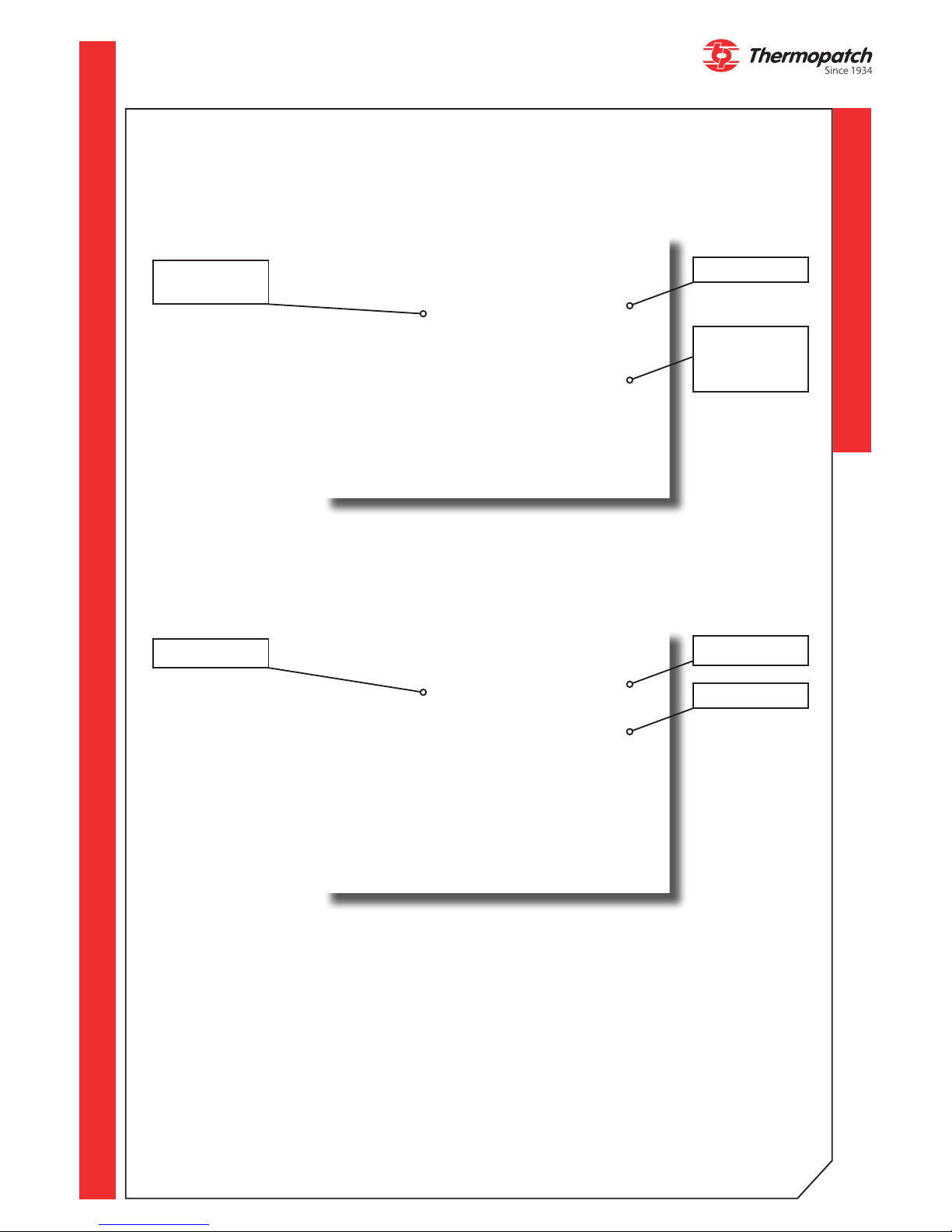
Presets
Date and
time
Actual temperature
Heat indicator
Timer left Timer right
resettable counter
Key for menu settings
decrease setting,
open next menu,
browse presets
increase setting,
open next menu,
browse presets
Touchscreen
Pressure
adjustment
knob
Emergency
Stop button
Manometer
Page 8

thermopatch.com
8
4.2.2 Settings by means of the touch screen
a) Presets
This menu contains 9 stored operating programs; for each of these 5 presets can be added
by entering the required parameters. The operating programs must be suited for the chosen
application. The temperature adjustment is set to each program.
Available programs:
Browsing program
presets
Browsing programs
End of cycle
buzzer settings
User comfort
settings
Sleeping mode Energy saving
Machine
settings
Diagnostic mode
Next screen
• Flex: for placing ex and ock
• DTG 1: for drying pre-treated materials
• DTG 2: for pressing pre-treated materials
• SUBLI T: for sublimation printing on textiles
• SUBLI R: for sublimation printing on rigid materials
• SCREEN: for placing screen transfers
• LASER: for placing laser transfers
• QUICKFLEX: for placing ex in under 5 seconds
b) Settings menu
Press the green button in the middle of the touch screen in order to open the settings
menu.
Press again to open the desired menu.
Press the arrow button in the middle, below to leave the settings screen.
c) Sleeping mode
Page 9
thermopatch.com
9
Internal menu
code
Internal menu
code
Start drying mode
The drying time is
set on the control
panel with the sealing time parameter.
Counters
Temperature in
sleeping mode
Error log
Start sleeping
mode
Switch on mem-
brane left
End sleeping
mode
Switch on mem-
brane right
Previous screen
The sleeping mode keeps the machine temperature to a certain level for a certain amount of
time.
d) Machine settings
e) User comfort settings
Page 10
thermopatch.com
10
f) Energy saving mode
°C -°F
Temperature
Time
Buzzer on - o
On - o
Set machine
temperature
range
The energy saving mode lowers the machine temperature to the set temperature after the
set time for that expires.
4.2.3 Full automatic mode
Page 11
thermopatch.com
11
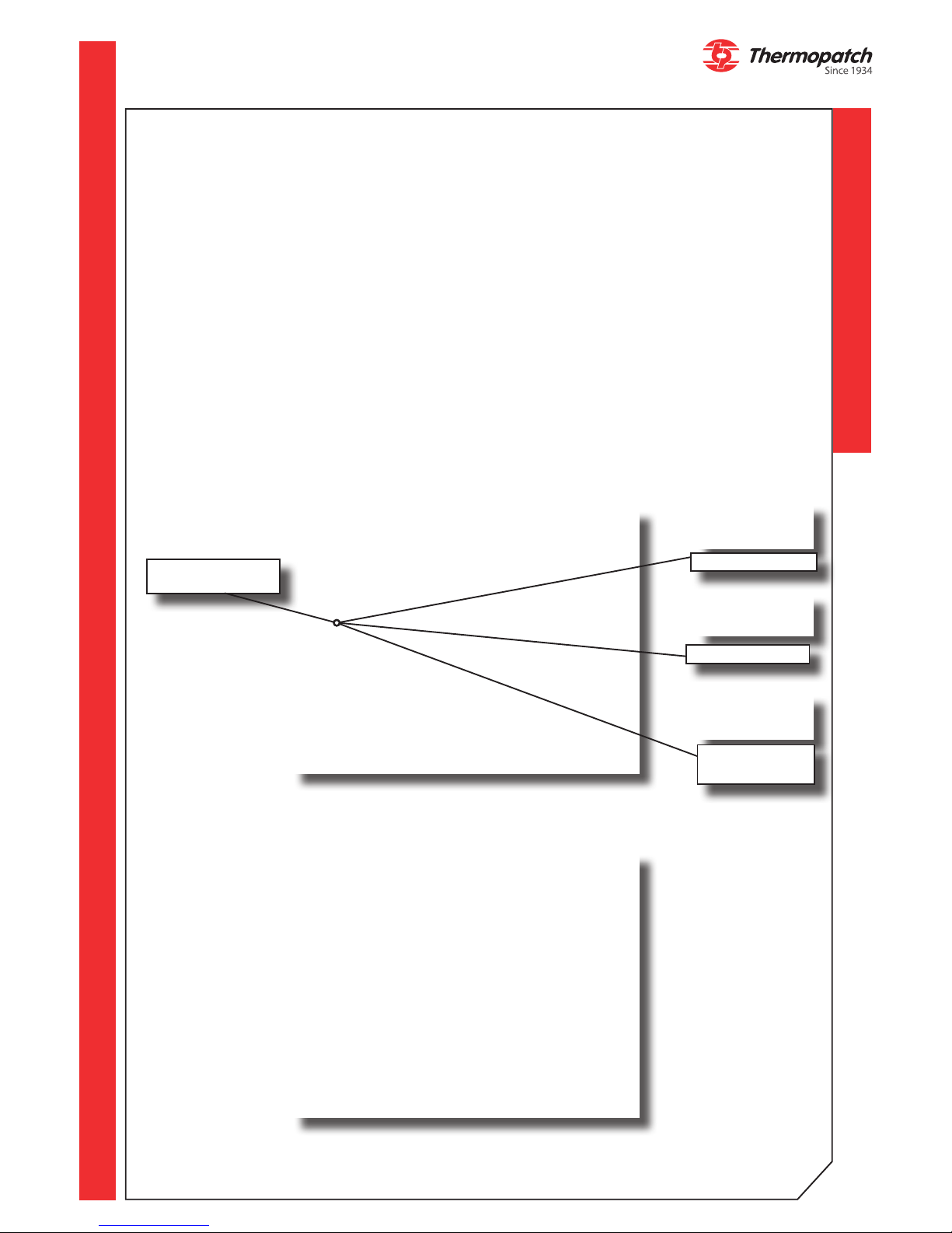
a) The NL-33 has 3 optional operation modes:
• Operation through a pedal
By pressing the foot switch, the press head will move to the other platen and will execute
the set press cycle there.
• Single work station
By pressing the foot switch the press head will move to the other platen en return back to
its position after nishing the press cycle.
• Fully automatic
By pressing the foot switch, the press head will move to the other platen. As soon as the
'post press' timer has count down, the press head will move to the start position and automatically start its cycle. This will be repeated until the operator presses the STOP iconon the
touch screen, or operates the foot switch.
Choosing the operation mode
c) Setting the 'Post-Press timer' (ONLY in Automatic mode)
Setting the opera-
tion mode
Fully automatic
Semi automatic
pedal operation
4.2.4 Error messages on screen:
Single workstation
Page 12
thermopatch.com
12
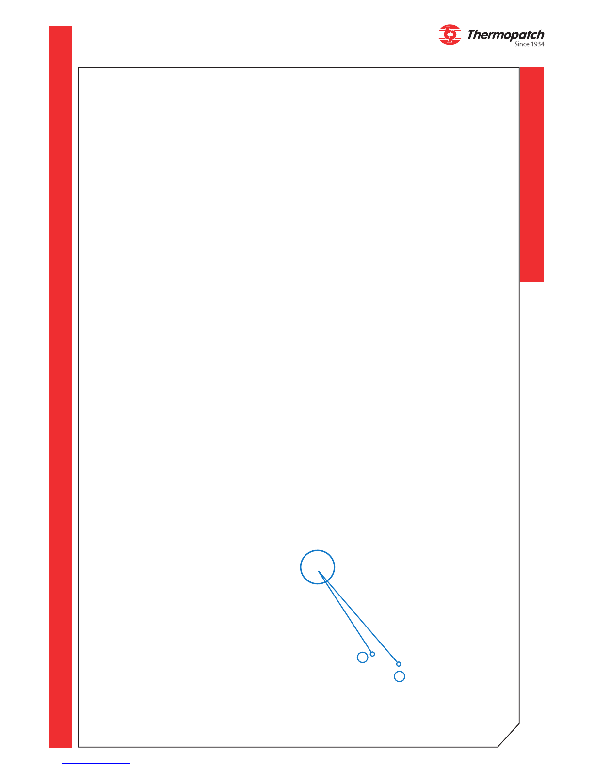
1
2
Alert 1: PT100 unplugged
Alert 2: Platen safety device
Alert 3: Triac 1 short-circuited
Alert 4: Triac 1 control out of order
Alert 5: Triac 1 relay short-circuited
Alert 7: Clock battery
Alert 8: Cylinder PR245 lift action
Alert 9: Cylinder PR245 lowering action
Alert 11: Machine cylinder manual lift
Alert 12: Heat platen timed out
Alert 14: PT100 > Max. temperature drop setpoint
Alert 15: PT100 > Max. permitted temperature setpoint
Alert 16: Triac 2 control out of order
Alert 17: Triac 2 relay short-circuited
Alert 18: RH travel limit not reached
Alert 19: LH travel limit not reached
Alert 20: Variance between lower travel limit and upper travel limit
Alert 21: Variance between RH travel limit and LH travel limit
4.3 Adjusting the setting for the automatic arm swing
1. Adjust the swing speed regularly with a tting screwdriver; due to deminishing lubrication and wear of the mechinical parts this will change.
• Turn the speed adjustment screw right to decrease speed.
• Turn the speed adjustment screw left to increase speed tegen de klok in, om de snelheid
te verhogen
2. When the press head bounces before or after pressing, the dampener should be adjusted
with an Allen key.
• Turn the Shock absorption adjustment screw to the right to increase dampening
• Turn the Shock absorption adjustment screw to the left to decrease dampening
Page 13
thermopatch.com
13
5. Overview of safety measures and
warnings
5.1 Safety
The NL-33 is equipped with all mandatory safety requirements that apply according to the
European guidelines for machine safety.
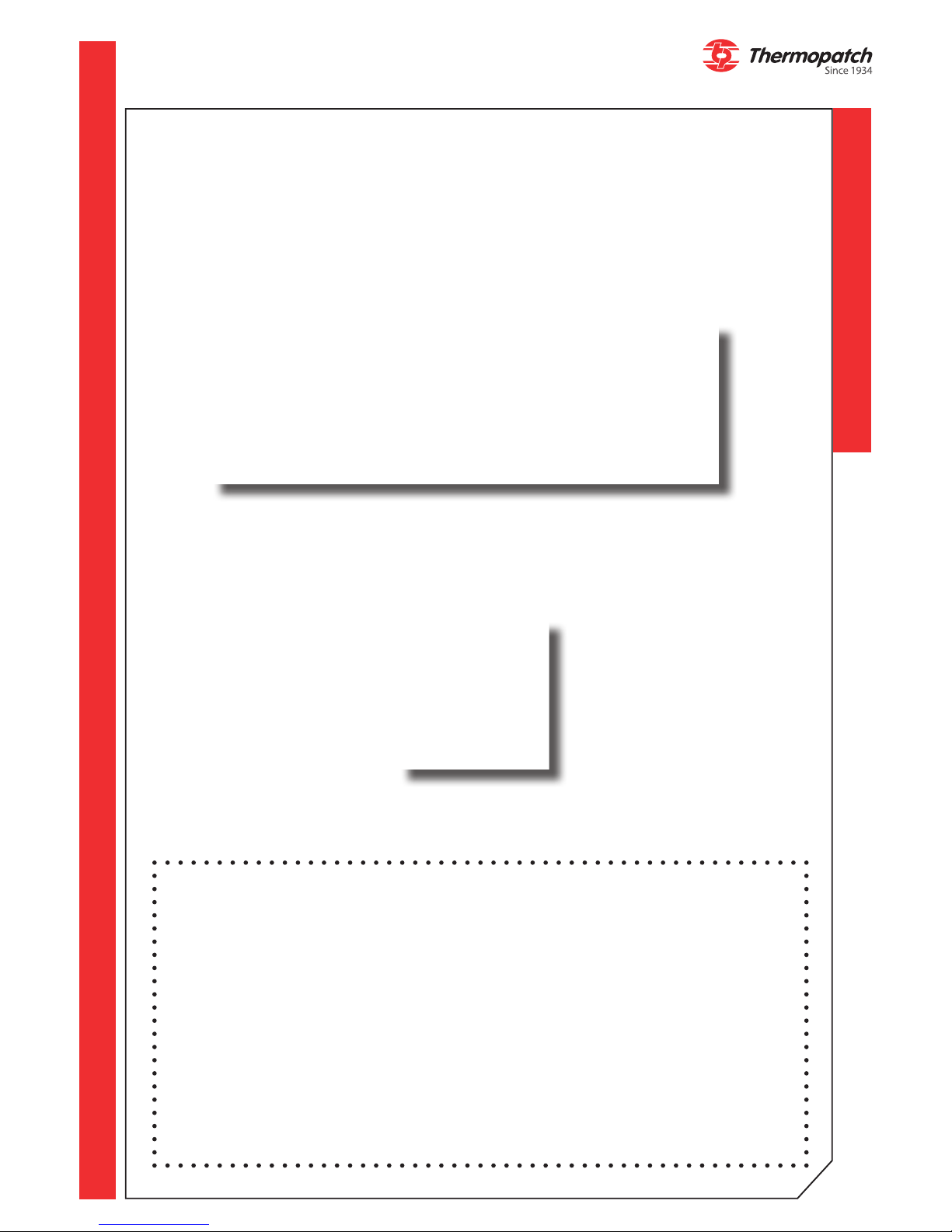
The safety frame
The heating element of the NL-33 is shielded with a safety rack. This is to prevent the risk
of pinching during heat sealing.
The emergency stop button
As required in the guidelines for machines, the machine is provided with an emergency
stop button.Press in case of emergency!
Turn the knob anti-clockwise to unlock again and the machine will reset automatically.
Warning symbols:
for additional safety the following symbols have been placed on the machine:
WARNING!
Hot surface
WARNING!
Electrical voltage
Page 14
thermopatch.com
14
ATTENTION!
Make sure you are informed about the contents of this manual before starting to work
with the NL-33. This ensures an optimal and safe use of the machine.
ATTENTION!
Always turn the power o (unplug it) when you need to carry out maintenance work or
when
cleaning the machine.
ATTENTION!
In case of emergency, press the emergency stop button!
ATTENTION!
Take care that there is enough space around the machine. Cables and connections must
not get pinched. Although the heat radiation of the press is low, there should be
enough space for cooling down.
ATTENTION!
Avoid contact with the press and the heating element.
ATTENTION!
Pull the fabrics tight around the lower platenn and ensure that your hands are away
from the machine before operating the machine
Page 15
thermopatch.com
15
6. Technical specications
6.1 Specifications of the NL-33
Energy consumption 3200 Watt
Connection voltage 220-240 Volt 50/60 Hz
Temperature adjustable up to max: 255°C (+/- 1%)
Height (open) 713 mm
Width 1071 mm
Diepte (met aansluitingen) 1005 mm
Net weight 153 kg
Dimensions of the press cushions 400 x 500 mm
Fuses 2 x T 16A 250 V
A -weighted sound pressure < 70 dB(A)
Compressed air consumption @ 4 bar 3.19 L/cycle
Compressed air consumption @ 6 bar 4.78 L/cycle
Compressed air consumption @ 8 bar 6.37 L/cycle
Prepressure > 3,5 bar - 8 bar
Maximum pressing force 925 DaN
Page 16
thermopatch.com
16
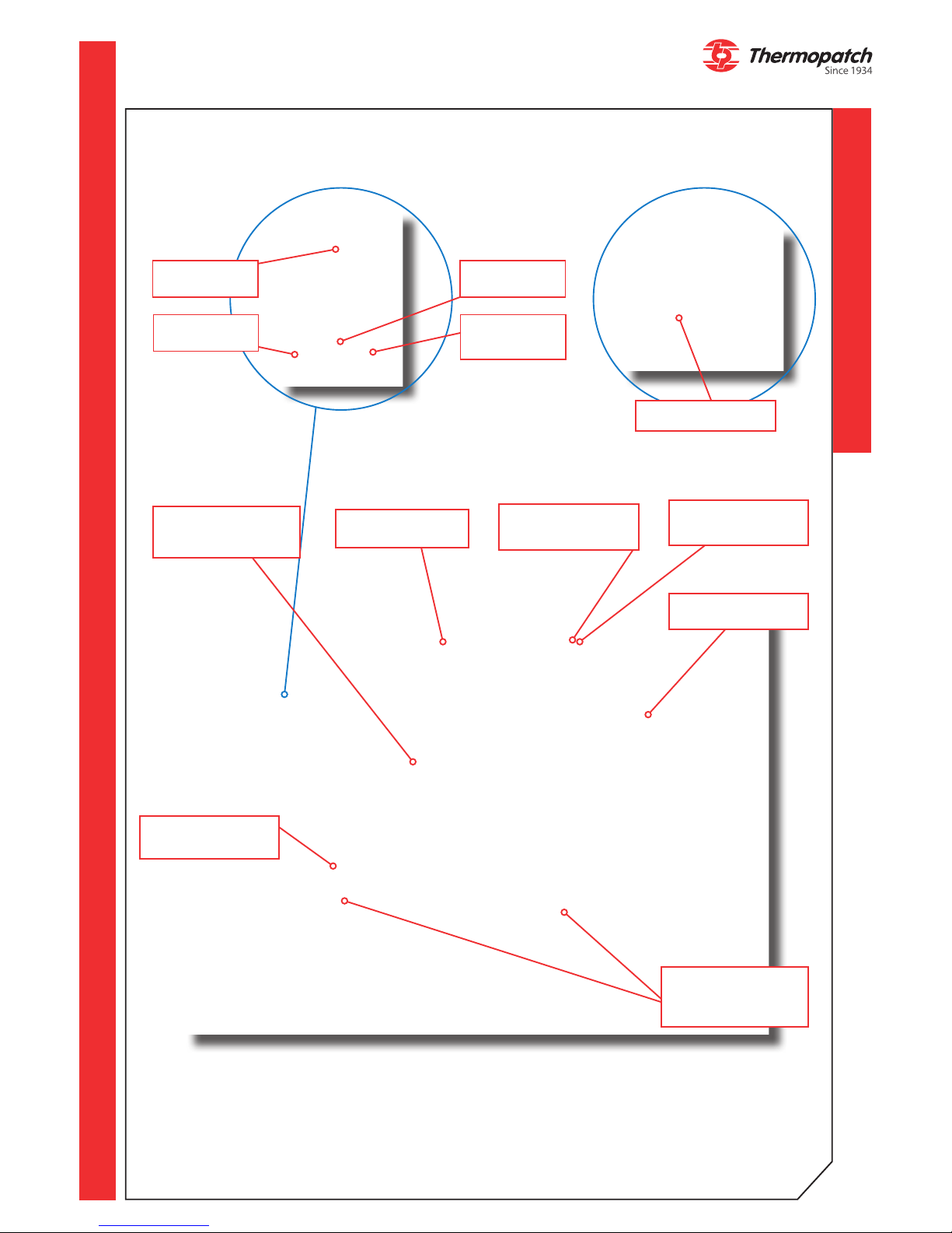
Hood + electronic
board
Plug and fuse box
Autoswing cilinder
Air pressure inlet
and air lter
Pedal
Heating platen with
safety frame
Connector
heating platen
2x exchangeable
under platens with
silicone rubber cush-
ions
Pressure
setting
Touchscreen
Emergency
stop button
Manometer
6.2 Overview
Page 17

thermopatch.com
17
7. Transport and storage
7.1 Transport
When the machine has to be moved, Thermopatch recommends to use the original
packaging.
7.2 Storage
If the machine has to be stored, Thermopatch recommends to use the original packaging.
The machine must be stored o the ground, preferably on a pallet in dry conditions.
Page 18
thermopatch.com
18
8. Maintenance
Make sure that the working cycle of the machine has ended before you start working on the
machine. Depending on the work to be performed, the power supply or the air supply can
be disconnected.
The air cylinder and other parts of the machine are virtually maintenance-free.
However, the condition is that clean and dry air is used for the heat seal machine. The
applied water separator / pressure regulator is an extra safety.
Have your machine serviced by technically qualied personnel. Moisture and polluted air
disturb the sustainable lubrication of the air cylinder.
Teon cover:
The teon lm protecting the element must be cleaned regularly to prevent sticking of la-
bels and patches or the transfer of dirt to the garments. Clean the Teon cover with a dry,
clean cloth while the machine is still warm. Repeat the process regularly as often as neces-
sary. Damaged or soiled Teon protection should be replaced. These are available from your
Thermopatch supplier.
Rubber cushion:
Clean the still warm rubber plate with a clean, lint-free cloth. Clean it as often as necessary.
Damaged or soiled rubber sheets must be replaced. These are available from your Thermopatch supplier.
Replacing the rubber cushion:
• Turn o the device and allow it to cool
• Make sure both the bottom metal plate and the rubber cushion are clean and free of
grease
• Apply SPA-AS1504 silicone adhesive (with a glue comb) to the metal plate and place the
rubber plate immediately with no air bubbles
• Allow to dry overnight at room temperature under light pressure without heating.
Air lter:
The air lter, or the water separator / pressure regulator, must be checked daily and, if nec-
essary, emptied by opening the cap on the underside of the lter.
Replace the fuses
Make sure that the machine is switched o and that the power cord is unplugged! Replace
the T16 A fuses at the back of the machine. Then plug in the power cord again and the machine is ready for use again.
ATTENTION!
Remove the plug from the wall socket BEFORE starting maintenance or repairs
Page 19
thermopatch.com
19
9. Technical annexes (English)
9.1 Spare Parts
Reference Description Quantity
ELECTRICAL PARTS
CAR-CO2 CONTROL BOARD 1
SPA27-005 MICA HEATING ELEMENT 400x500 2500W 1
SPA3X-024 TEMPERATURE PROBE 1
SPA3X-003 FUSE 5 x 20 mm T 16 A 250 V
2
PNEUMATIC PARTS
VER-SM29 CYLINDER Ø100 C50 1
FIL-013 AIR FILTER 1
ELE-SM3 SOLENOID CONTROL VALVE 5/2 G1/8 12V 1
TEFLON and SILICONE RUBBER
SPA3X-100-7 FOAM 9.53 mm 400 x 500 1
SPA3X-019 TEFLON SHEET 1
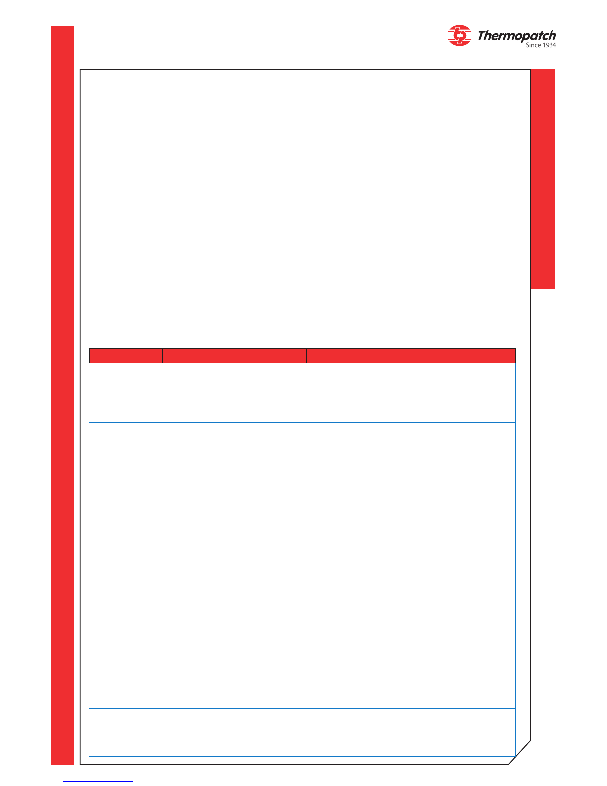
9.2 Troubleshooting
Problem Possible cause Solution
The machine
does not
switch on
• The plug is not connected
• The switch has not been
switched to 'on'
• Main fuse is not working
• Check the connection to the electric
mains and if the machine is plugged in
• Press the main switch to 'on
• The fuse is located in the fuse holder
next to the power cord connector.
The heating
platenn does
not heat up
• Faulty heating element
• Problem with the main
board
• Temperature set too low
• Check the connections and the condi-
tion of the wiring
• Remove the heating element
• Check the on-screen messages and
refer to the section error messages,
page 9
The heating element
overheats
• Problem with the probe
of electronic board
• Check de messages on the LCD
screen, page 9
• Contact your supplier
The timer
does not
count down
• Disabled or faulty cylinder sensor
• Problem with the electronic board
• Check the connections
• Check the on-screen messages and
refer to the section error messages,
page 9
The press
head does
not lower
• The buttons are not
working
• Leaking cylinder
• Too low pressure on air
supply
• Check the connections
• Check the seals and all connections,
contact your supplier
• Check the valve couplings, contact
your supplier for replacement
• Check that the air supplied is above 3
bar
The press
head does
not come up
• Faulty solenoid control
valve
• Leaking cylinder
• Check the valve couplings, contact
your supplier for replacement
• Check the seals and all connections,
contact your supplier
The press
head stays
down after
pressing
• The timer is not counting
down
• See above
Page 20
thermopatch.com
20
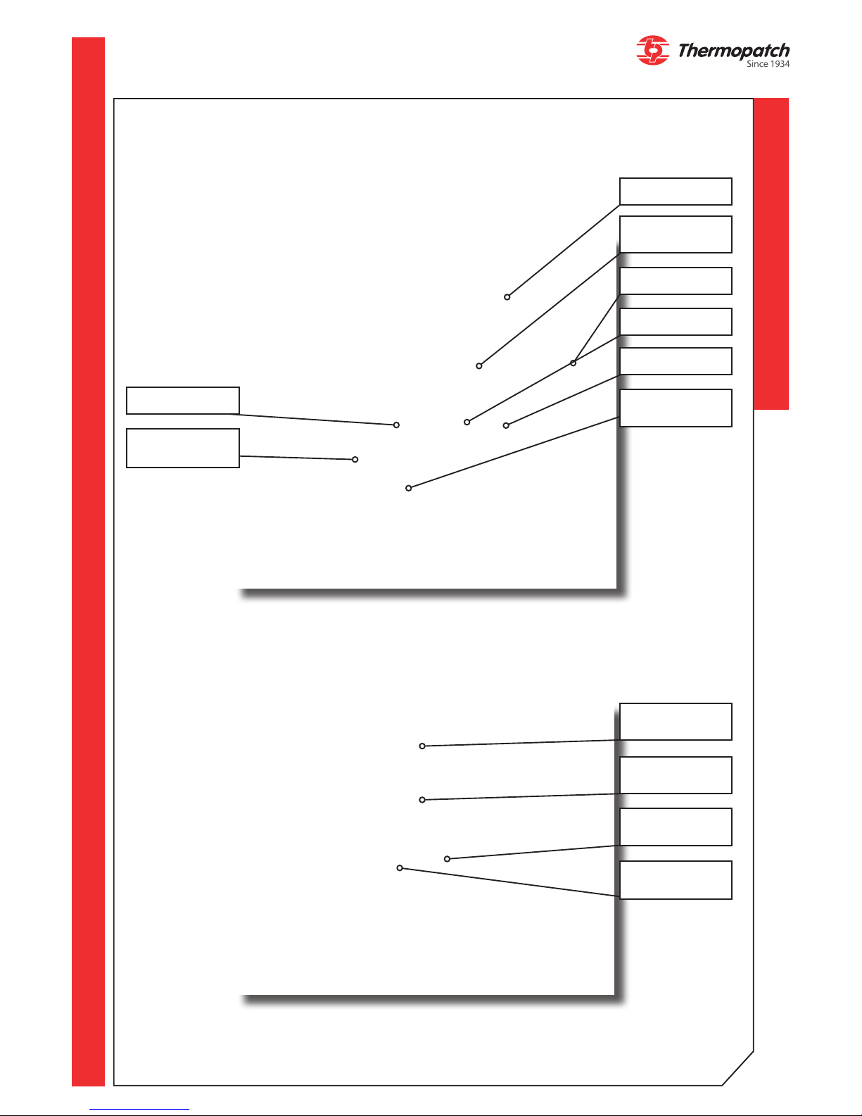
9.3 Drawings with parts
Press Cylinder
Safety sensors
Filter
Power inlet and
fuse box
Control board
Press cylinder
Magnetic sensor
UPPER travel limit
Magnetic sensor
LOWER travel limit
Swing controller
Air supply connec-
tion
Cylinder stop
Press function
solenoid valve
Page 21

thermopatch.com
21
9.4 Electric diagram
Thermopatch B.V. Draaibrugweg
14, 1332 AD Almere, Netherlands
NL-33
ELECTRIC
DIAGRAM
Page 22

thermopatch.com
22
9.5 Pneumatics diagram
PNEUMATICS
DIAGRAM
NL-33
Thermopatch B.V. Draaibrugweg
14, 1332 AD Almere, Netherlands
Page 23
thermopatch.com
23
10. End of life
Choose to dispose of the machine responsibly when it has reached its end of life.
Electrical machinery, accessories and packaging should be recycled as much as possible in
an environmentally responsible manner.
- Dismantle the machine groups: steel parts / pneumatic components / electrical components
- These can be separated and returned for recycling.
ATTENTION!
Always dispose according to current and locally applied guidelines for health and
safety and disposal requirements.
Page 24
thermopatch.com
24
11. Declaration of conformity
We,
Thermopatch B.V.
Draaibrugweg 14
1332 Almere
Netherlands
Declare under our own responsability that the heat sealing machine:
Thermopatch NL-33,
which this declaration refers to, is in accordance with the conditions of the following Directive(s):
2014/30/EU (emc directive)
2006/42/EG (machinery directive)
Netherlands, Almere, 01-02-2018
Jan Bausch,
Director
Page 25

thermopatch.com
25
12. Disclaimer
The information contained in these documents is condential, privileged and only for the
information of the intended recipient and may not be used, published or redistributed
without the prior written consent of Thermopatch B.V.
The opinions expressed are in good faith and whilst every care has been taken in preparing these documents, Thermopatch B.V. makes no representations and gives no warranties
of whatever nature in respect to these documents, including but not limited to the accuracy or completeness of any information, facts and/or opinions contained therein.
Thermopatch B.V., its subsidiaries, the directors, employees and agents cannot be held li-
able for the use and reliance of the opinions and ndings in this document.
For any warranty Thermopatch B.V. refers to its general terms and conditions.
We can conrm that the machines we supply conform to CE when in standard conguration.
Using sealing pads of any format other than the standard supplied with the machine may
render the CE declaration invalid.
Thermopatch accepts no responsibility for any damage or injury that may result from possible non-conformity.
Choosing an alternative conguration other than the standard is at the customer’s own
responsibility.
Page 26

thermopatch.com
Thermopatch Corporate Headquarters USA T +1 315 446-8110 F +1 315 445-8046 [email protected]
Thermopatch European Headquarters The Netherlands T +31 36 549 11 11 F +31 36 532 03 98 [email protected]
Thermopatch Australia Pty Ltd Australia T +61 395325722 F +386 2 80 55 232 [email protected]
Thermopatch Canada Inc Canada T +1 519 748-5027 F +1 519 748-1543 [email protected]
 Loading...