

Thermopatch HS11 Operation & Service Manual
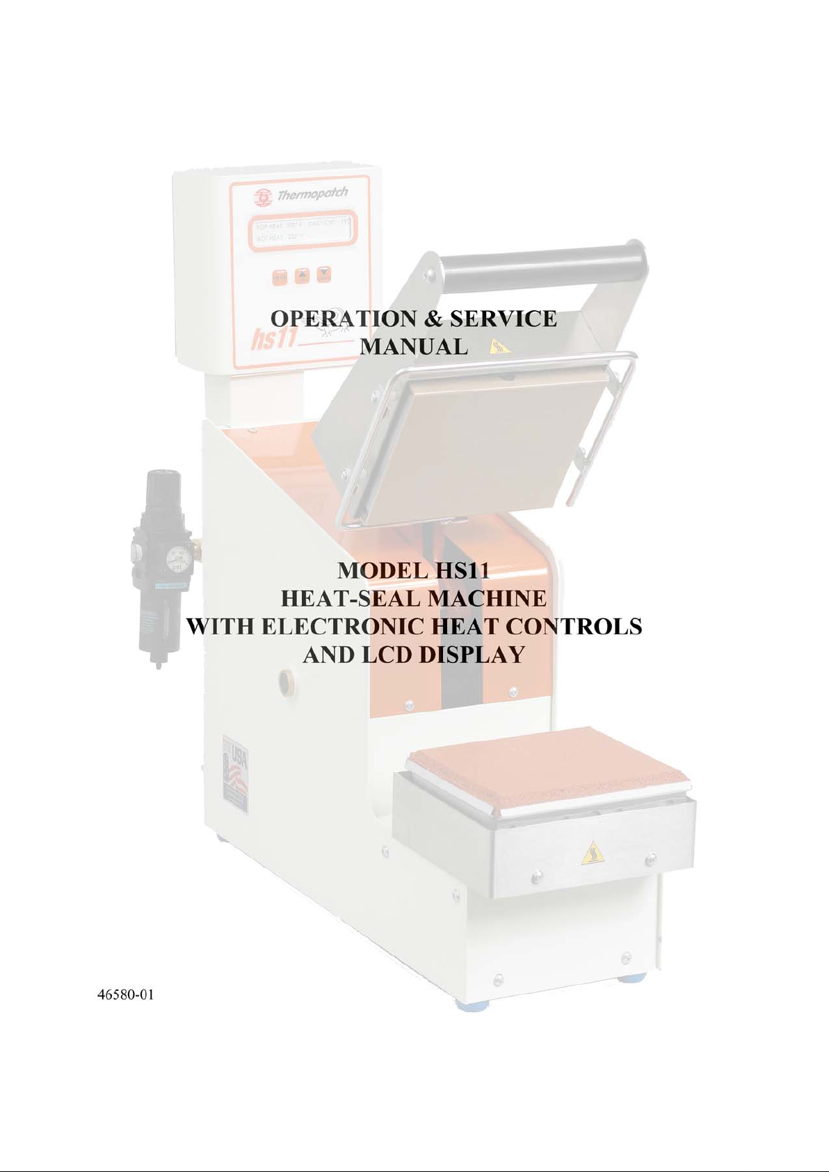

TABLE OF CONTENTS
WARRANTY II
SECTION 1 1-1
Introduction to the HS11 1-1
Safety Information 1-1
Machine Specifications 1-2
Operating Specifications 1-2
SECTION 2 2-1
Installation and Set-Up 2-1
SECTION 3 3-1
Machine Operation 3-1
Sealing Pads 3-3
Start-Up Screens 3-4
Menu Screens 3-5
Error Screens 3-6
SECTION 4 4-1
Operations and Problem Analysis 4-1
Problem Analysis and Solutions 4-2
SECTION 5 5-1
Maintenance 5-1
SECTION 6 6-1
Parts Identification and Location 6-1
SECTION 7 7-1
Customer Service 7-1

ii
WARRANTY
Thermopatch Corporation, Syracuse, New York ("Seller") warrants this product to be free from defects in
material and workmanship under normal use and service. Any part which proves to be defective in
material or workmanship within one (1) year of the date of original purchase for use will be repaired or
replaced, at Seller's option, free of service or labor charges, with a new or functionally operative part.
Seller's liability under the Warranty shall be limited to repairing or replacing at its own factory or through
an authorized service distributor or dealer, material which is determined by Seller to have been defective
in manufacture and upon which a claim has been made by the original purchaser or user to Seller (or an
authorized distributor or dealer) within the warranty period. Claims under this Warranty will be honored
only upon written approval by an authorized officer of Seller. Approved return of parts or products will
be on a prepaid transportation charges basis only. Claims under this Warranty will be honored only upon
Seller's determination that the claim is covered by this Warranty, and Seller shall incur no obligation
under this Warranty prior to such determination. This Warranty does not apply: (1) To any machinery or
equipment which has been altered or repaired, except by Seller or its authorized representatives, or (2) to
any machinery or equipment which has been subject to misuse, negligence, or accident, including,
without limitation, use and operation of such machinery or equipment while parts are loose, broken, out
of order, or damaged by the elements. Parts replaced under this Warranty are warranted only through the
remainder of the original Warranty. Any and all claims for warranty service must include such
information as Seller designates, and shall include specifically the serial number of each unit (if
appropriate).
The foregoing shall constitute the sole and exclusive remedy of any using purchaser and the sole and
exclusive liability of Seller in connection with this product. THIS WARRANTY IS IN LIEU OF ALL
OTHER WARRANTIES, EXPRESS, IMPLIED OR STATUTORY, INCLUDING BUT NOT LIMITED
TO, ANY WARRANTY OF MERCHANTABILITY OR FITNESS AND ALL OTHER OBLIGATIONS
OR LIABILITIES OF SELLER, INCLUDING ANY TORT LIABILITY, FOR NEGLIGENT DESIGN
OR MANUFACTURE OF THIS PRODUCT, OR OTHERWISE. It is expressly agreed that Buyer shall
not be entitled to recover any incidental or consequential damages, as those terms are defined in the
Uniform Commercial Code, and that Buyer shall have no right of rejection or of revocation of acceptance
of any part or of revocation of acceptance of any part or all of the goods covered hereby.

1-1
Section 1
INTRODUCTION TO THE HS11
The HS11 is designed as a heavy-duty heat-seal machine for applying patches, emblems, hot paper
transfers, and identification tapes.
The sealing cycle is initiated by hand, which causes the sealing head to lower.
Temperature, time, and sealing pressure can all be individually adjusted as required for the particular
materials being sealed. Upper and lower platen temperatures can be set independently in Fahrenheit or
Celsius. A new LCD screen with 3-button interface simplifies machine operation.
The machine develops 24 PSI inter-platen pressure with the standard 5” x 6” platens. Two optional
smaller platens are available for even higher inter-platen pressure.
SAFETY INFORMATION
Each HS11 is equipped with a safety-lock feature for the protection of the operator. The pneumatic
sealing cycle will not start until the upper sealing plate is within 5/32” (4mm) of the lower sealing platen.
If an obstruction is met before this point, the sealing cycle will not occur. THE SAFETY LOCK
FEATURE IS PRESET AND SHOULD NOT BE TAMPERED WITH.
In addition to the safety lock feature, there is a touch guard around the upper heater platen. Should any
obstruction contact the touch guard, the machine will become inoperative. An error message will appear
on the LCD screen, see Alarm Display Screens, page 3-6.
CLEAN MACHINE PARTS WITH NON-FLAMMABLE CLEANING FLUIDS ONLY!
CAUTION: WORKING AIR PRESSURE MUST NOT EXCEED 70 PSI (4.8 BAR)! AIR
SUPPLY SHOULD NOT BE CONTAMINATED WITH DIRT, OIL, OR WATER.
The electrical system is three-wire and fully grounded. THIS THREE-WIRE ELECTRICAL POWER
CORD AND PLUG MUST ALWAYS BE USED WITH A PROPERLY GROUNDED OUTLET.
WARNING
: THE SEALING IRONS MAY REACH TEMPERATURES AS HIGH AS
450qF(232qC) DURING NORMAL OPERATION. APPROPRIATE CARE
SHOULD BE TAKEN TO PREVENT SKIN BURNS. ALWAYS KEEP HANDS
CLEAR OF THE SEALING IRONS AND TOUCH GUARDS WHEN
OPERATING MACHINE!
Two back-up high limit thermostats prevent the temperature of either sealing iron from rising above
500qF (260qC) in case either heat control malfunctions.
Before operating, make sure all covers are in place, and keep loose jewelry and clothing clear of machine
during operation.
Before servicing machine, unplug electrical power cord, disconnect air supply, and let sealing irons cool.

1-2
MACHINE SPECIFICATIONS
Electrical requirements: 10 amp @ 110 VAC, 50/60 Hz
or
5.0 amp @ 220 VAC, 50/60 Hz
Maximum operating air pressure: 70 PSI (4.8 Bar)
Time settings: 1.0 – 30 seconds
Heat range: 150q - 450qF (66q - 232qC)
Shipping weight: 65 lbs (29.5 kg)
Length (open): 20” (51 cm)
(closed): 23” (58 cm)
Height (open): 21” (53 cm)
(closed): 21” (53 cm)
Width: 8” (20 cm)
Sealing iron size: 5” x 6” (13 x 15 cm)
Sealing pad size (standard): 5” x 6” (13 x 15 cm)*
(optional): 2” x 4” ( 5 x 10 cm)*
(optional): 1-3/16” x 4” ( 3 x 10 cm)*
Pedestal (optional): 32” (81 cm) high
Garment tray (optional): 17” x 25” (43 x 64 cm)
*See page 3-3 for inter-platen pressure.
OPERATING SPECIFICATIONS
Temperature
The HS11 heat-sealing machine will require approximately 10-15 minutes for the temperature to stabilize.
Check the digital readout for upper and lower platen temperatures.
CAUTION: NEVER EXCEED 450qF (232qC), THE MAXIMUM SEALING IRON
TEMPERATURE!
Sealing temperatures have been preset to: 425qF (218qC) upper iron
375qF (191qC) lower iron

1-3
Sealing Pressure
Sealing pressure is factory-preset at 60 PSI (4.1 Bar).
Time
CAUTION: NEVER EXCEED 70 PSI (4.8 Bar), THE MAXIMUM OPERATING PRESSURE!
Heat-sealing cycle time is factory set to 10.0 seconds. The sealing time can be changed as required to
apply or remove a label.
To adjust time or temperature settings, press the MODE key, and follow page 3-5, “Menu Screens”. To
adjust sealing pressure, see page 3-1 “Operating Instructions”.

2-1
Section 2
INSTALLATION AND SET-UP
Worktable Mounting
1. Set the machine on the worktable in desired location.
2. Draw a pencil line on the table at the front edge of the machine, near the center.
3. Move the machine out of the way and measure back 2” (5 cm) from the pencil line.
4. Drill a 9/32-inch (7 mm) diameter hole for a sheet metal table, or 3/16-inch (5 mm) diameter hole
for a wood table.
5. Mount the wood screw or shoulder bolt (supplied).
6. Reposition the machine so the keyhole slot in the bottom cover (at the front) drops over the head
of the screw.
7. Push the machine back slightly. (Note: The purpose of this screw is to prevent the machine from
bouncing or moving across the table.)
Pedestal Mounting (optional)
Mount per separate instructions included with the pedestal.
Garment Tray (optional)
The garment tray can be mounted so it is either level with the rubber platen, or reversed so it is about 5”
(13 cm) below.
1. Remove two screws from each side of the machine.
2. Place the garment tray in the desired position and attach with the four screws.
Completing the Installation
1. Attach filter assembly to air inlet at rear of machine. Use pipe thread sealant or tape.
2. Hand-tighten or tighten lightly with a pipe wrench on the short piece of pipe between the machine
and air filter.
3. Plug the electrical power cord into a properly grounded outlet of the correct voltage/amperage
rating.

3-1
Section 3
MACHINE OPERATION
Operating Instructions
1. Turn the “Power” switch to ON. The amber light on the switch will light indicating power is
being supplied. Allow approximately 10- 15 minutes for the temperature to stabilize.
2. Adjust upper and lower sealing temperatures as needed, see page 3-5 “Menu Screens–Screen2,3”.
WARNING
: THE HEATED PLATENS MAY REACH TEMPERATURES AS HIGH AS 450qF
(232qC) DURING NORMAL OPERATION. APPROPRIATE CARE SHOULD BE
TAKEN TO PREVENT SKIN BURNS. ALWAYS KEEP HANDS CLEAR OF THE
HEATER PLATENS AND TOUCH GUARD WHEN OPERATING MACHINE!
3. Adjust pressure as needed. Turn the large black knob clockwise to increase pressure,
counterclockwise to decrease. Check air gauge and repeat as needed.
DO NOT EXCEED 70 PSI!
To Apply a Patch or Emblem (non-embroidered):
1. Set the sealing time to desired period by pressing the up or down keypads to the proper setting
(see page 3-5 “Menu Screens – Screen 4”).
2. Center the workpiece over the lower sealing pad.
3. Place the patch, emblem, etc. over the workpiece with the adhesive side toward the fabric.
4. When hands are clear of the touch guard, grasp the upper sealing head handle and lower the
sealing head.
5. As soon as the upper iron comes all the way down to the lower platen, release.
The upper iron will automatically stay down to complete sealing. The digital display will show elapsed
time for the sealing cycle. When it reaches the set seal time, the upper iron will automatically return to the
upright position.
CAUTION: FOR BEST RESULTS, SEALED MATERIAL SHOULD BE HANDLED
CAREFULLY UNTIL IT HAS COOLED TO ROOM TEMPERATURE.
To Remove a Patch or Emblem:
1. Set the sealing time to the desired period by pressing up or down on the keypads (see page 3-5
“Menu Screens – Screen 4”).
2. Place the workpiece on the pad so the patch is centered.
3. Lower the upper platen until the sealing cycle begins.
4. When the upper iron releases, quickly peel the patch or emblem off the surface of the workpiece.
5. If the patch cools before it is removed, repeat the procedure.
CAUTION: USE EXTREME CARE IN HANDLING THE FABRIC. IT WILL BE VERY HOT!

3-2
Applying Embroidered Emblems
Embroidered emblems and emblems with embroidered borders (also called merrowed borders) are a
special case and usually should be sealed as follows:
See Section 5 “Maintenance” to remove the Teflon shield from the upper platen and to remove the sponge
rubber pad from the lower platen.
1. Mount the Teflon shield to the lower platen and the sponge rubber pad to the upper platen.
2. Readjust the temperatures so that the lower platen is at 410qF (210qC) and the upper platen is at
375qF (191qC).
3. Set pressure at 60 PSI (4.1 Bar) for the 5” x 6” (13 cm x 15 cm) platen.
4. Set at 12 seconds. This can be varied between 10 seconds (for light fabrics) and 14 seconds (for
heavy fabrics), see page 3-5 “Menu Screens – Screen 4”.
5. Follow procedure for non-embroidered emblems, see above.
Note: For very thick garments, it may be necessary to increase the time setting even higher, since it is
very difficult to get the heat through the garment.

3-3
SEALING PADS
Part No. 42477
(Standard)
42515
(Optional)
42516
(Optional)
Size 5” x 6”
(13 cm x 15 cm)
4” x 2”
(10 cm x 5 cm)
4” x 1-3/16”
(10 cm x 3 cm)
Material Silicone sponge rubber Silicone sponge rubber
(firm)
Silicone hard rubber (solid)
Use For: Applying mending
patches, emblems, hot
paper transfers and
label tapes to garments
and linens
Applying smaller-sized
heat-seal products, or
for higher sealing
pressure than standard
platen
Smallest size applications,
spot sealing, applying
labels to confined areas of
garments, such as between
trouser belt loops, where
extremely high inter-platen
pressure is required
INTER-PLATEN PRESSURE
42477 42515 42516
Gauge Air
Pressure
PSI (Bar)
PSI (Kg/cm
2
) PSI (Kg/cm2) PSI (Kg/cm2)
15 (1.0) 5 (0.4) 19 (1.3) 32 ( 2.3)
20 (1.4) 7 (0.5) 26 (1.8) 43 ( 3.0)
25 (1.7) 8 (0.6) 32 (2.2) 54 ( 3.8)
30 (2.1) 10 (0.7) 38 (2.7) 64 ( 4.5)
35 (2.4) 12 (0.8) 45 (3.1) 75 ( 5.3)
40 (2.8) 14 (1.0) 51 (3.6) 86 ( 6.0)
45 (3.1) 15 (1.1) 57 (4.0) 97 ( 6.8)
50 (3.4) 17 (1.2) 64 (4.5) 107 ( 7.5)
55 (3.8) 19 (1.3) 70 (4.9) 118 ( 8.3)
60 (4.1) 20 (1.4) 76 (5.4) 129 ( 9.1)
65 (4.5) 22 (1.6) 83 (5.8) 140 ( 9.8)
70 (4.8) 24 (1.7) 89 (6.3) 150 (10.6)

3-4
ENSURE TOUCH GUARD
IS CLEAR #####
START-UP SCREENS
The HS11 heat-sealing machine is equipped with a LCD display. When power is switched on to the
machine, the following start-up screens will be visible:
Screen 1:
THERMOPATCH
ALLIGATOR
Screen 1 is the first screen to appear when power is switched on.
Screen 2:
TOUCH GUARD TEST
RING=123 WIRE=456
Screen 2 appears while the machine self-tests the touch guard. Actual numbers may be different. If the
touch guard is activated, the following screen will appear. The start-up process will continue when the
touch guard is cleared.
Screen 3:
PERFORMING SELF TEST
PLEASE WAIT
Screen 3 appears while the machine self-checks its circuits..
Screen 4:
HEATING PLEASE WAIT UNIT READY FOR
UPPER 410F LOWER 375F OR PRODUCTION
(A) (B)
Screen 4(A) appears while the upper and lower heat platens are being heated to the default or user-set
Fahrenheit temperatures. If the user changes the temperature scale to Celsius during heating, the
temperatures will be displayed in degrees Celsius (e.g. 105C). Screen 4(B) appears if the machine is
turned on while the platens are at the default temperature.
Screen 5:
UPPER=410F TIME=10.0
LOWER=375F DC=123456
Screen 5 appears after the heat platens reach the default or user-set temperatures. The machine is now
ready to seal. The upper and lower temperatures are shown at left, the time and daily count (DC) at the
right. To change any of these values, see the following section “Menu Screens”

3-5
MENU SCREENS
The default settings in the HS11 heat-sealing machine can be changed as required.
To advance a menu screen, press the MODE key. To change the value or select an option, press the up or
down key. If no button is pressed for 8 seconds, the machine will exit the menu.
The following menu screens will appear in sequence:
Screen 1 (select temperature scale):
F/C SELECT SET=F
UP=C DN=F MODE=NEXT
Screen 1 appears when the MODE key is first pressed. The current temperature scale is indicated in the
upper right as an “F”, for Fahrenheit (default), or “C”, for Celsius. Press the UP key to change to Celsius.
Press the DOWN key to change to Fahrenheit. To advance to Screen 2, press the MODE key.
Screen 2 (set upper platen temperature):
SET UPPER TEMP=410F
UP=+ DN=- MODE=NEXT
Screen 2 appears when the MODE key is pressed as described above. The upper platen temperature is
displayed in the upper right, in the temperature scale chosen at Screen 1. Press the UP key to raise and the
DOWN key to lower temperature. The temperature can be changed in 2qF or 1qC increments.
To advance to Screen 3, press the MODE key.
Screen 3 (set lower platen temperature):
SET LOWER TEMP=375F
UP=+ DN=- MODE=NEXT
Screen 3 operates like Screen 2, setting the temperature for the lower platen. The lower platen
temperature is displayed in the upper right (shown is the default, 375qF). The temperature can be changed
in 2qF or 1qC increments.
To advance to Screen 4, press the MODE key.
CAUTION: DO NOT EXCEED 450qF (232qC) AT EITHER PLATEN!
Screen 4 (set seal time):
SET SEAL TIME=10.0
UP=+ DN=- MODE=NEXT
Screen 4 appears when the MODE key is pressed at Screen 3. The seal time is shown in the upper right
hand corner (shown is the default, 10.0 seconds). The seal time can be changed in 0.1 second increments
from 1.0 to 30.0 seconds. Press the UP key to increase and the DOWN key to decrease seal time.
To advance to Screen 5, press the MODE key.

3-6
TOUCH GUARD ACTIVE
PRESS ANY BUTTON
TOUCH GUARD WIRE
BROKEN-NOTFUCTIONAL
ENSURE TOUCH GUARD
IS CLEAR #####
Screen 5 (reset daily count):
DAILY COUNT=123456
DN=RESET MODE=NEXT
Screen 5 appears when the MODE key is pressed at Screen 4. The daily counter, displayed at upper right,
is the number of seals since the counter was last reset. To reset the counter, press the DOWN key, then
the MODE key to advance to Screen 6.
To continue without resetting the counter, simply press MODE to advance to Screen 6.
Screen 6 (information and exit):
TOTAL COUNT=12345678
PRESS MODE TO EXIT
Screen 6 appears when the MODE key is pressed at Screen 5. This screen displays the total seal count,
and is for information only. The total seal count cannot be changed.
Press the MODE key to exit and resume machine operation.
ERROR SCREENS
The following screens represent error messages shown in the digital display. Each screen is followed by
an explanation of the error, and the appropriate action to take.
Touch Guard Errors
The touch guard has been activated by contact. Keep hands clear of touch guard, and press any key to
resume operation.
There is a fault in the touch guard wire. This prevents the machine from operating without the touch
guard safety feature. This message will continue to appear until the wire is fixed. Turn off the machine,
and repair the wire before operating.
The touch guard was activated during startup. The startup sequence continues normally once the touch
guard is cleared.

3-7
NO HOOK SEAL RELEASE
HOOKSEAL OR SOLENOID
LOST HOOK SEAL SWITCH
PLEASE TRY AGAIN
UPPER HEATER FAILURE
PRESS ANY KEY
LOWER HEATER FAILURE
PRESS ANY KEY
LOWER HEATER > 250C
FAIL – PRESS ANY KEY
LOWER HEATER > 482F
FAIL – PRESS ANY KEY
UPPER HEATER > 250C
FAIL – PRESS ANY KEY
UPPER HEATER > 482F
FAIL – PRESS ANY KEY
Hook Seal Errors
The hook seal switch did not release within 4 seconds after elapsed seal time. The seal made is counted,
and the switch should release the upper sealing arm automatically. This message indicates a possible
failure of the solenoid that controls the hook seal switch.
The hook seal switch lost contact before the seal cycle was completed. The cycle is not counted. The
sealing arm reset automatically. Wait for the arm to reset, and try the seal again.
Heater and Temperature Errors
The heater did not reach the set temperature in 20 minutes. Press any key. Try to set a lower temperature.
If this error message re-occurs, there may be a more serious failure (see Problem Analysis and Solutions).
The heater has exceeded its maximum safe temperature, or a thermocouple or circuit board has failed.
Machine operation will stop and an alarm will sound. Press any key to silence the alarm and return to
normal mode. Shut down machine and check thermocouple and circuit boards. Repair or replace as
needed before resuming operation of machine.
CAUTION: HIGH TEMPERATURES CAN DAMAGE MACHINE AND CAUSE PERSONAL
HARM. DO NOT OPERATE IF HEATER FAILURE MESSAGE APPEARS!

4-1
Section 4
OPERATIONS AND PROBLEM ANALYSIS
Sequence of Operations
Connect air supply – no electrical operations; sealing head in upright position.
Switch power on – heat goes on, switch light goes on, LCD screen displays start-up menus.
Pull sealing head down – microswitch engages, energizing solenoid valve, engaging sealing hook. Timer
is activated and begins counting
Timer times out – seal arm solenoid valve is de-energized, returning sealing platen to top position.
If power goes off (or machine is unplugged) the sealing platen stays in the up position.
If air is removed sealing platen remains up.

4-2
PROBLEM ANALYSIS AND SOLUTIONS
Before referring to the information below, check for proper set-up and operation as outlined in Sections 2
and 3.
Solutions are listed with the most probable ones listed first.
Some procedures may require completion by a person with some mechanical skill. See Section 6 for
Customer Service assistance or to order replacement parts.
PROBLEM POSSIBLE CAUSE SOLUTION
-Machine is unplugged or outlet has no power -Check
-Electrical power switch or light is not “ON” or is defective
-Bad fuse at power entry module
-Check/Replace
-Check/Replace
Power “ON” light
not lighted
-Loose or broken wires or connections -Check/Repair
-Machine is unplugged or outlet has no power -Check
-Electrical power switch is not “ON” or is defective -Check/Replace
-Blown fuse on circuit board -Replace
-Defective sealing iron -Replace
-Defective heat sensor -Replace
-Defective temperature control -Replace
-Defective high-limit thermostat -Replace
No heat
-Loose or broken wires or connectors -Check/Repair
-Defective heat sensor -Replace
-Defective temperature control -Replace
High or low heat
-Short between sensor wires (high heat only) -Repair/Replace
-Leak in air supply hose -Repair/Replace Sealing pressure
drops, fluctuates,
or hisses
-Dust, oil, or water in air lines, regulator, or solenoid air
valves
-Disassemble and clean
-Garment or cloth is too thick -See Section 3-3
-Leak in hose or connections -Repair/Replace
-Defective micro switch -Replace
-Solenoid air valve not shifting -Disassemble and clean
or replace
-Mechanical binding -Check/Correct
-Cracked sealing hook -Replace
-Cracked sealing arm -Replace
-Missing or broken pins or cam rollers -Replace and add grease
Timed sealing
cycle does not
activate
-Loose or disconnected wiring -Check/Correct
-Air solenoid valve not shifting -Check/Replace Sealing head does
not fully rise
-Leak or restriction in air line or connections -Check/Repair
-Insufficient sealing time -Increase time
-Insufficient sealing pressure -Increase sealing pressure
-Insufficient temperature -Increase temperature on
Teflon platen
-Sponge rubber pad is worn -Replace
Heat transfers or
patches, etc. not
bonded properly to
garment
-Teflon cloth covers for upper/lower platens are worn -Clean/Replace
-Sealing time too long -Decrease by 2 second
increments
Adhesive bleed
through
-Sealing pressure too high -Decrease sealing air
gauge pressure by 5 PSI
or .5 Bar increments

5-1
Section 5
MAINTENANCE
Teflon/Fiberglass Shield
Clean often by wiping with a soft, clean rag. A non-flammable cleaner such as “EZ-Off”, part number
DH-6873, may be used according to the manufacturer’s instructions. Never use a flammable solvent or
abrasive cleaner! To ensure the best heat-sealing results, regularly replace shield whenever it becomes
torn or too soiled to clean.
From the side, gently wedge a screwdriver between the sealing iron and the aluminum backing plate. The
shield may now be removed by applying gentle pressure. Being careful of the heat, install the new shield
by holding it against the sealing iron and pressing to snap it into position.
Rubber Sealing Pads (without Teflon Cover)
Clean often by wiping with a soft, clean rag. Replace the pad when it becomes worn.
Note: To replace the rubber sealing pad, use the same procedure as for the shield.
Compressed Air Supply
Maintain a filtered air supply. Check air filter daily. Drain by pushing up on button at bottom of filter
bowl.
General
Keep inside of machine free of foreign material, including lint.
Lubrication
Place one drop of standard lubricating oil (SAE 10 or equivalent) at the following locations once a month:
x Pivot shafts for sealing arm: at both ends of shaft where it enters case (See Upper Iron and
Chassis Assembly)
x Air cylinders: where the rod enters the cylinder (See Machine Chassis Assembly)
x Sealing hook, pins, and cam rollers: both rollers and pins in the sealing hook and sealing arm
(See Sealing Hook and Bracket Assembly, Fulcrum Arm and Chassis Assembly)
Be sure to wipe off any excess oil.
 Loading...