

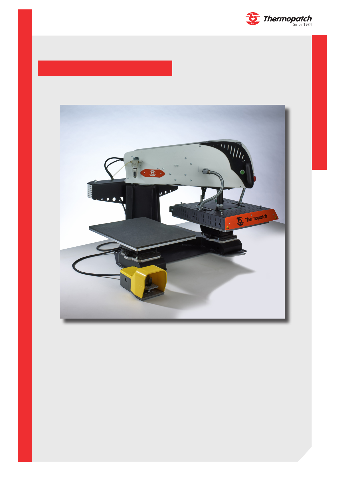
NL-33 Auto Maxi
User manual
These instructions must be made available to all persons involved in the assembly,
commissioning, operation, maintenance and repair of this product
thermopatch.com
Eng V1.1
JUN 2019 Original V1.1
ATTENTION!

Copyrights
© 2019 Thermopatch bv, Almere, The Netherlands.
No part of this publication may be reproduced by any means without the prior written
permission of Thermopatch bv, The Netherlands.
Thermopatch, the Thermopatch logo, Thermo Seal and Thermocrest are registered
trademarks of Thermopatch.
Introduction
The products by Thermopatch are designed with special attention to your convenience.
Should you discover any fault or damage upon receipt of this product, please contact your
local Thermopatch vendor.
The manual has been prepared in accordance with NEN 5509 and in conformity with the Machinery Directive 2006/42/EC.
This user manual is intended not only for all users of the machine, but also for those who
install and maintain the NL-33. The goal is to familiarize you with the operation, to provide
for safe working instructions and guidelines for maintenance.
ATTENTION!
In order to make safe and optimal use of the NL-33 it is important to take notice of -
and understand the contents of this manual.
thermopatch.com
2

Contents
Copyrights 2
Introduction 2
Contents 3
1. General description 4
1.1 Delivery 4
1.2 Warranty and product liability conditions 4
2. Intended use 4
3. Assembly and installation 5
3.1 Unpacking 5
3.2 Electrical installation (1) 7
3.3 Pneumatic installation (2) 7
4. Operating Instructions 8
4.1 Operating the NL-33 8
4.2 Operating the control panel 8
4.2.1 Setting the temperature and the heat sealing time 10
4.2.2 Description of the heat sealing cycle 11
4.2.3 Parameters 12
4.2.3.1 Status bar 12
4.2.3.2 Digital keypad 12
4.2.3.3 Presets 13
4.2.3.4 Settings menu and diagnosis 14
4.2.3.5 Ergonomic settings 15
4.2.3.6 Energy mode 15
4.2.3.7 Time and date 17
4.2.3.8 Information 17
4.2.3.9 Factory settings 18
5. Diagnosis 19
5.1 Alarms and warnings 19
5.2 Summary alarms and incidents 20
5.2.1 List of alarms and incidents 21
6. Operating Cycle 22
6.1 Number of timers 23
7. Overview of safety measures and warnings 24
7.1 Safety 24
8. Technical specications 26
8.1 Specifications of the NL-33 Auto Maxi 26
9. Transport and storage 28
9.1 Transport 28
9.2 Storage 28
10. Technical Manual 29
10.1 Maintenance 29
10.1 Replacement parts list 30
10.2 Troubleshooting 30
10.4 Electrical wiring diagram 34
10.5 Pneumatics diagram 35
11. End of life 36
12. Declaration of conformity 37
13. Disclaimer 38
thermopatch.com
3
1. General description
The pneumatic NL-33 is a practical, universal heat seal machine. Textile labels, emblems,
repair patches, transfers, in short all Thermopatch materials for marking and repair are
easily and durably pressed onto textile fabrics.
1.1 Delivery
The NL-33 machines are delivered on a pallet covered with a wooden crate.
In the delivery of your NL-33 machine you will nd the following:
• NL-33 heat seal machine
• Footswitch
• Power cord
• Air tube 6 mm
• CE declaration with serial number
• Quick installation guide
• Quality checklist
• Manual including the CE declaration, on CD-ROM
1.2 Warranty and product liability conditions
Thermopatch points to its warranty and product liability conditions as laid down in our terms
and conditions. These can be obtained from your Thermopatch supplier.
2. Intended use
The NL-33 heat seal machine is practical and universally applicable.
The machine is designed for applying transfers, emblems and other Thermopatch heat seal
products.
WARNING!
Any use other than described above can be dangerous and cause damage and thus
qualies as ‘misuse’ which excludes Thermopatch bv from any liability.
thermopatch.com
4
3. Assembly and installation
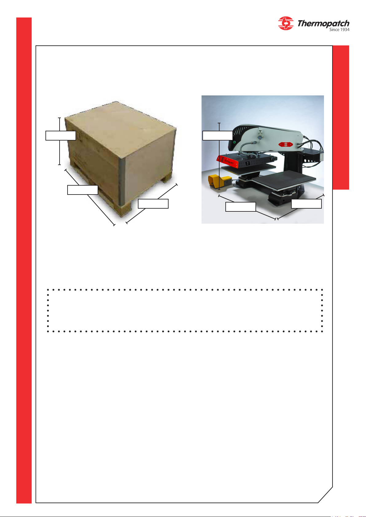
3.1 Unpacking
905 mm 713 mm
1180 mm
1000 mm 891 mm
• Remove the straps and the wooden protective crate.
• Use a 10 mm spanner to remove the four screws with which the machine is screwed to
the pallet.
• Remove the security screw using the Allen key 4 provided (2).
• Center the press between both plates.
1099 mm
WARNING!
Do not transport the machine by lifting it by the plates!
This will cause damage to the machine.
thermopatch.com
5
1
2
• Place the lifting bars which are packed with the machine. Place the short bar on the back
and the long bar on the front.
• NEVER LIFT THE MACHINE BY THE PLATES
• Lift the machine onto the work table by means of the lifting bars that are mounted front
and back (1).
• Place the sealing plates if they are not already mounted.
• Remove the transport bars from the machine.
• Connect the compressed air supply with a minimum pressure of 4 bar.
• Store the lifting bars for future use.
thermopatch.com
6
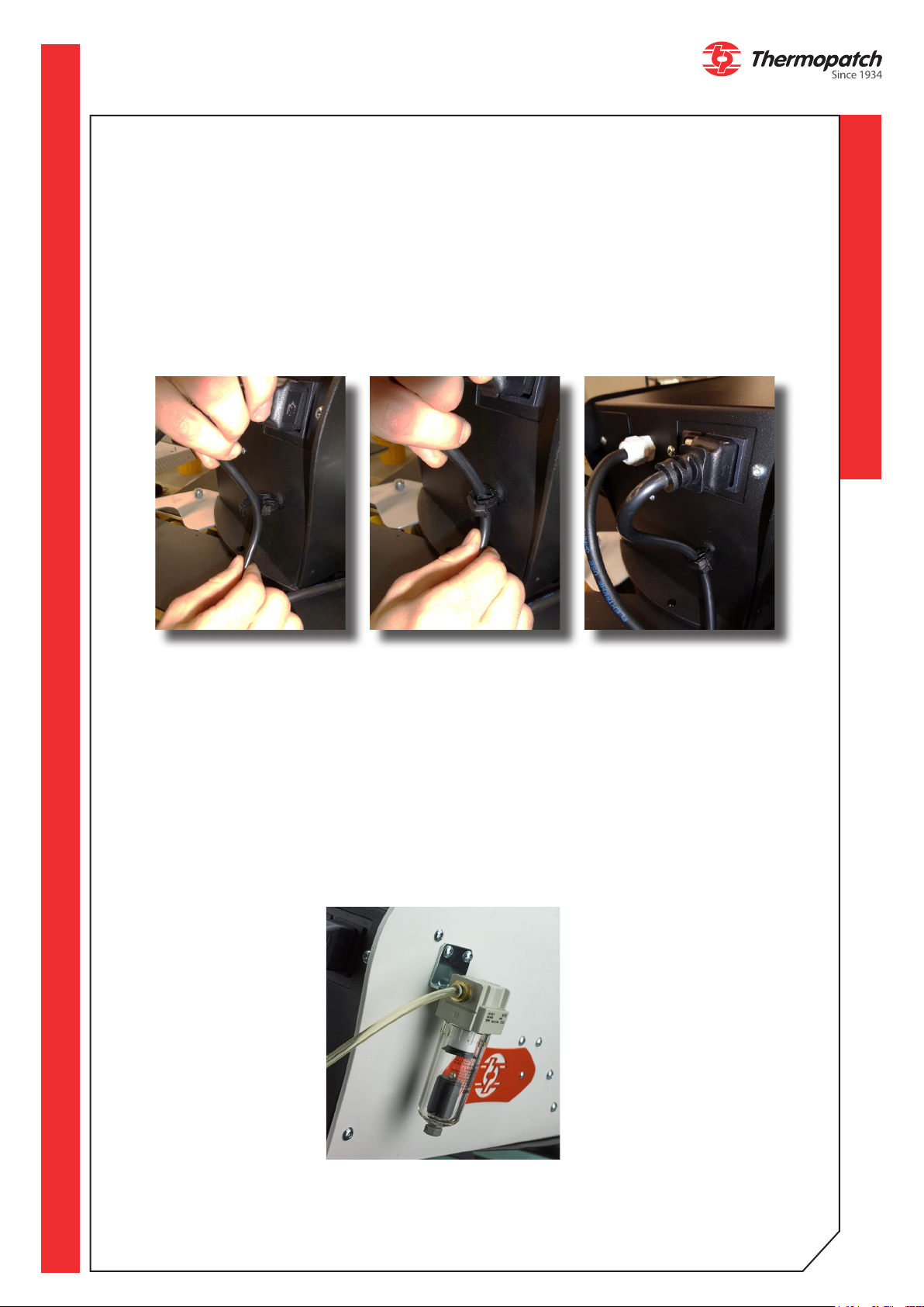
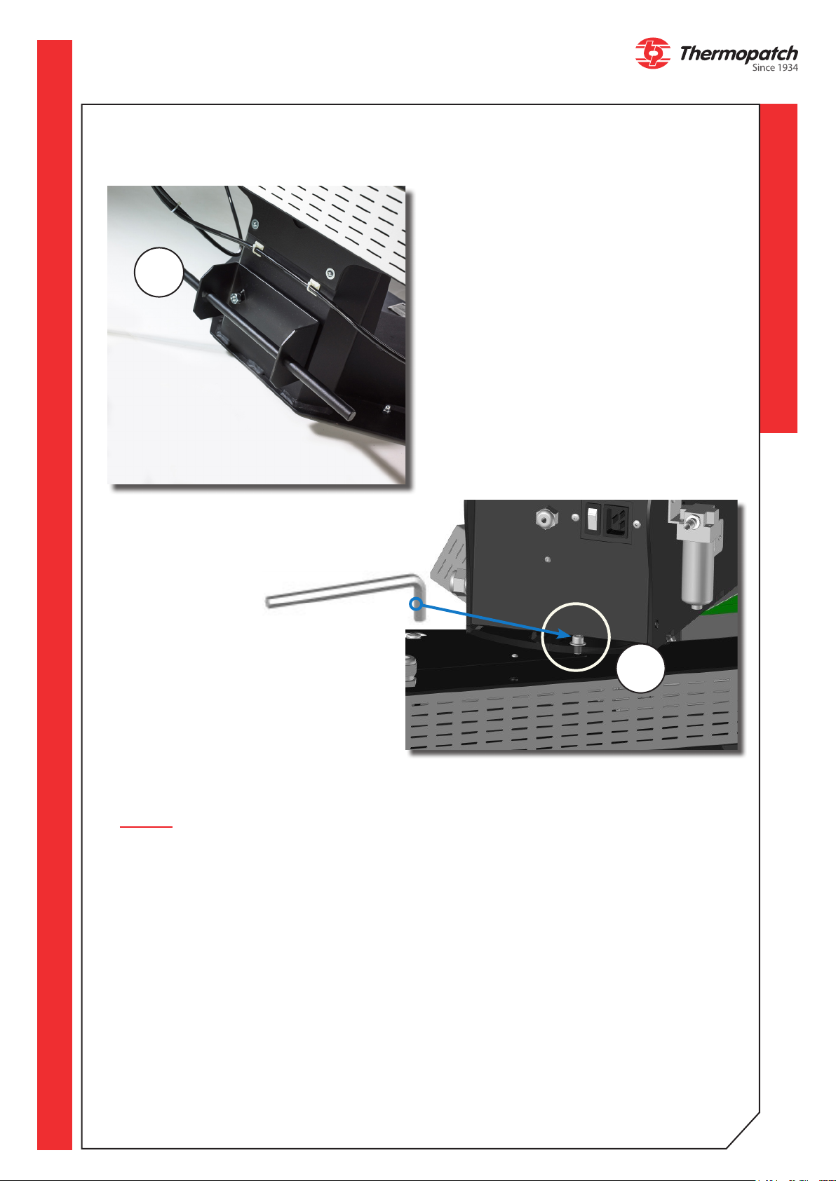
3.2 Electrical installation (1)
Take the NL-33 out of the box by using the lifting bars and place the machine on a stable
work table in the vicinity of a grounded socket. The NL-33 is connected to the power supply (230 V alternating current) with the supplied power cable. The NL-33 is grounded and
equipped with two fuses type T 16 A.
Place the power cord in the safety clip, which is mounted underneath the power switch on
the back of the machine, see below instruction.
place the cord in
front of the clip.
3.3 Pneumatic installation (2)
In order to be able to work with the NL-33 without problems, it is very important that you
work with clean, dry air that is oered at a minimum of 4 bar up to a maximum of 8 bar.
The supplied water separator / pressure regulator is only an additional protection for the
machine. The user must ensure that the air pressure does not exceed 8 bar. Connect an air
tube with a diameter of 6 mm to the locally provided air pressure system and connect it to
the water separator / pressure regulator of the NL-33.
close the clip The power cord is
safely mounted
thermopatch.com
7
4. Operating Instructions
4.1 Operating the NL-33
• Switch on the press by pressing the power switch located at the rear.
• Check that the Emergency Stop button is unlocked.
STOP button
• The touchscreen will show above start page.
• Tap the screen to access the following pages.
• Set the desired temperature according to the chosen type of transfer.
• Set the desired time according to the chosen type of transfer.
• Set the desired pressure by turning the pressure adjustment knob in the middle, below
the display. Turn left to decrease the heat sealing pressure, turn right to increase the
heat sealing pressure.
• Check the set pressure on the manometer which is mounted to the left of the pressure
adjustment knob.
4.2 Operating the control panel
The settings for temperature and time are displayed on the control panel (page 9).
1. Measured temperature and temperature setting (0 to 220 °C):
• The thermometer symbol shows RED when the temperature is above the set value
• The thermometer symbol shows BLUE when the temperature is below the set value
• The thermometer symbol shows
2. Time
3. Name of active preset
4. Status bar (HEAT - CYCLE - ECO MODE - WARNING)
5. Daily counter / Working mode
6. Active timer
7. Next timers (4 possible timers)
8. Preset button
9. Settings button
10. Exchange plate button - STOP during cycle .
The green two-hand control buttons on the side and the footswitch allow the start of the
heat sealing cycle. This is only possible when this start page on the touch screen is visible.
For a quick shut down, two modes are available:
• Press the STOP button
• Press the footswitch or green two-hand control: the plate goes up, moves to the opposite plate and stops moving.
: the plate goes up, and the press stops moving.
WHITE when the temperature is at the set value
thermopatch.com
8
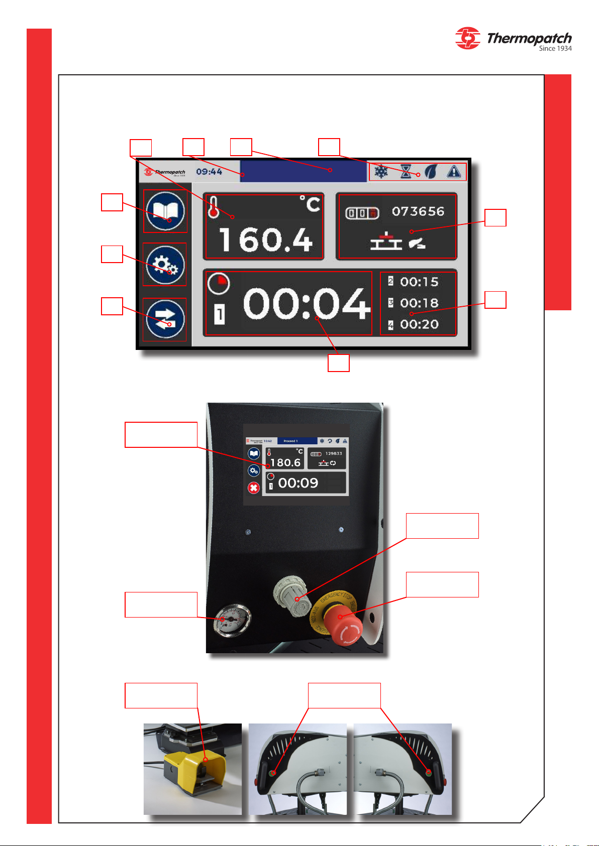
Control panel and other operating features
8
9
10
1
Touchscreen
2
3
Proceed 1
4
5
7
6
Manometer
Operating
footswitch
thermopatch.com
Pressure
adjustment
Emergency
Stop
Bi-manual
control
9
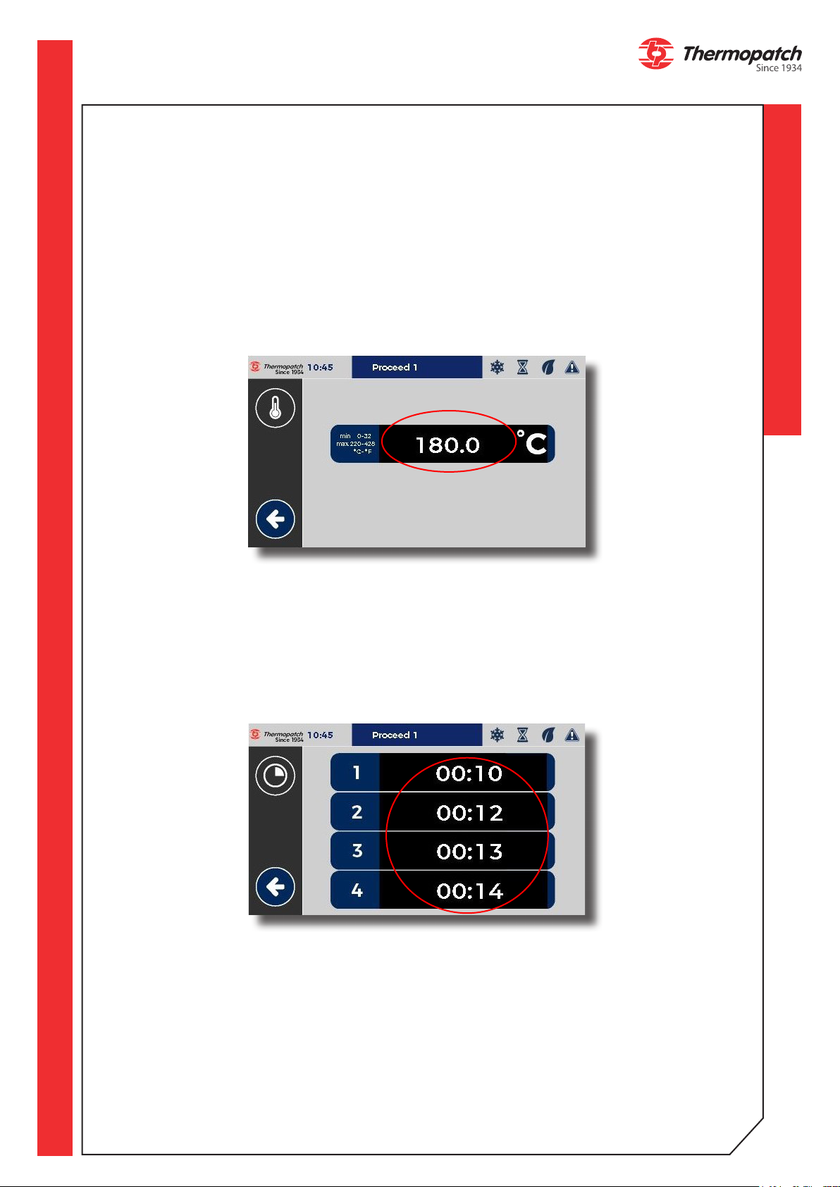
4.2.1 Setting the temperature and the heat sealing time
a) Temperature
• Touch the area of the screen where the temperature is indicated.
• Press the temperature setting.
A numeric keypad appears to enter the new value. This value is immediately entered in the
current preset.
Press the arrow at the bottom to return to the work screen.
b) Time
• Touch the area of the screen where the timers are indicated.
• Then enter using the numeric keypad each value of the timers.
Press the arrow at the bottom to return to the work screen.
These values are immediately entered in the current preset.
thermopatch.com
10
c) Counters and modes
• Press 3 seconds on
to reset the daily counter
• A totalizer is located below.
To change the operating mode press the following button:
• A: Mode single plate
• B: Mode Semi-Auto (footswitch)
• C: Mode Auto
A B C
d) Adjusting the swing speed of the press
• Please contact your supplier to adjust this setting.
Proceed 1
4.2.2 Description of the heat sealing cycle
• Rotate the heating plate to the opposite side of the one where you want to work.
• Test by pressing the footswitch or the green push button to validate your choice.
1. Place the item on the sealing plate.
2. Place the transfer.
3. Press the footswitch or the green buttons in order to start the heat sealing cycle. The
press arm automatically moves to the sealing plate, the heating plate automatically descends and activates the heat sealing timer.
4. Meanwhile, prepare the item and its transfer on the second station.
5. At the end of the countdown of the heat sealing timer, the heating plate will go up again.
6. If the machine is not in "FULL AUTO" mode, press the footswitch to activate the heat
sealing cycle. When in 'FULL AUTO" the rotation will be done automatically after raising
and counting o the "timer after pressing" (see c. Counters and Modes, above).
7. Remove the item from the rst and prepare the next item.
8. Repeat the operation at the third point.
During the cycle, pressing the footswitch or any one of the green pushbuttons stops the cycle and releases the pressarm from the opposite side.
During the cycle, pressing the stop button
on the screen stops the pressing cycle.
thermopatch.com
11
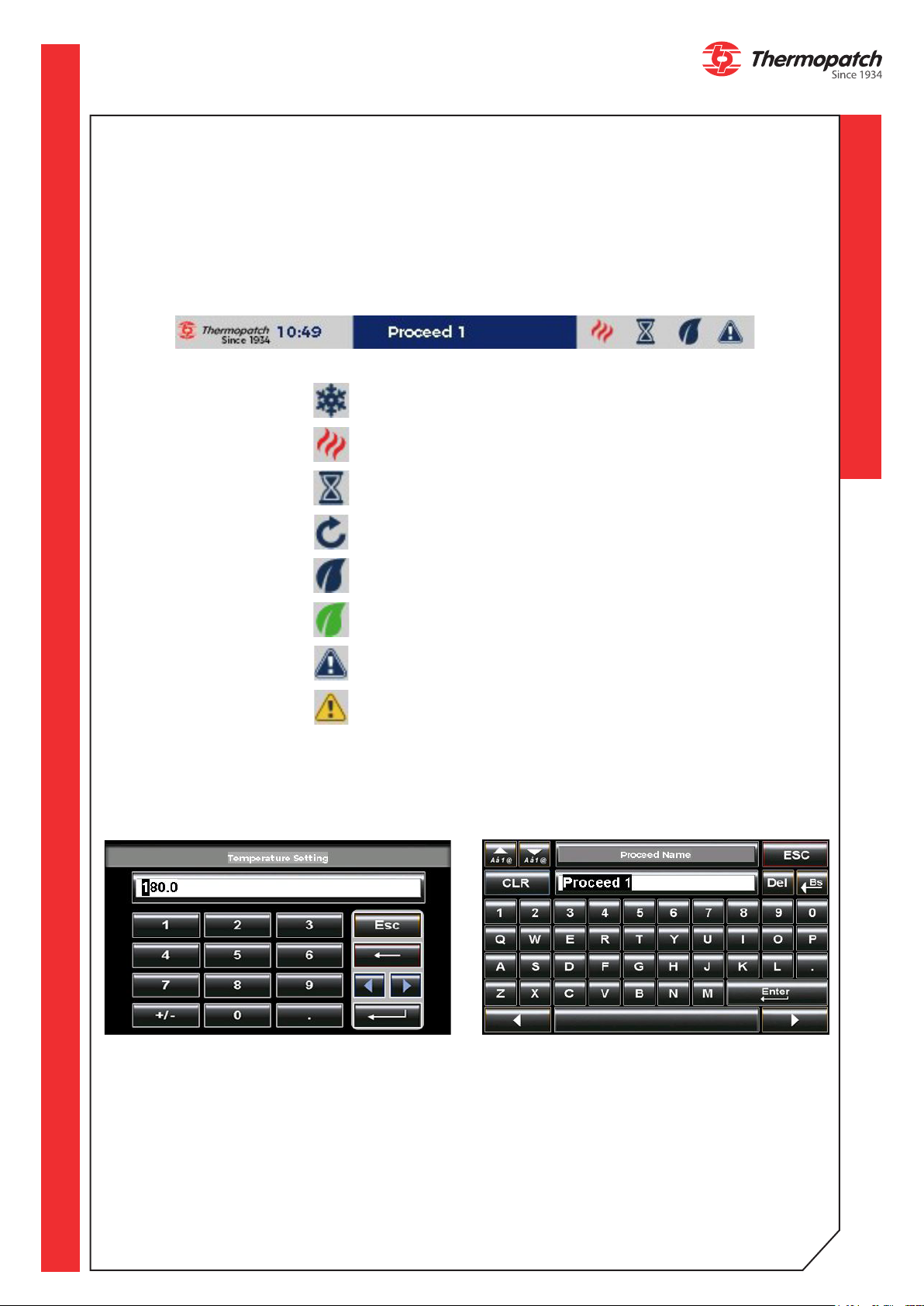
4.2.3 Parameters
4.2.3.1 Status bar
The status bar allows you to know the status of the machine on any activated page.
These symbols are not interactive; they are for information only.
LOGO TIME CYCLEACTIVE PRESET ECO WARNINGHEAT
Heating status:
Blue ake = stop
STATUS
Red ame = on
Cycle:
Machine = ready to work
Cycle = in progress
Eco mode:
Eco mode = OFF
Eco mode = ON
Warnings:
No active warning
Active warning
4.2.3.2 Digital keypad
The numeric keypad allows you to enter values such as temperature or times. An alphanumeric keyboard allows you to enter the name you want to give to the preset.
thermopatch.com
12

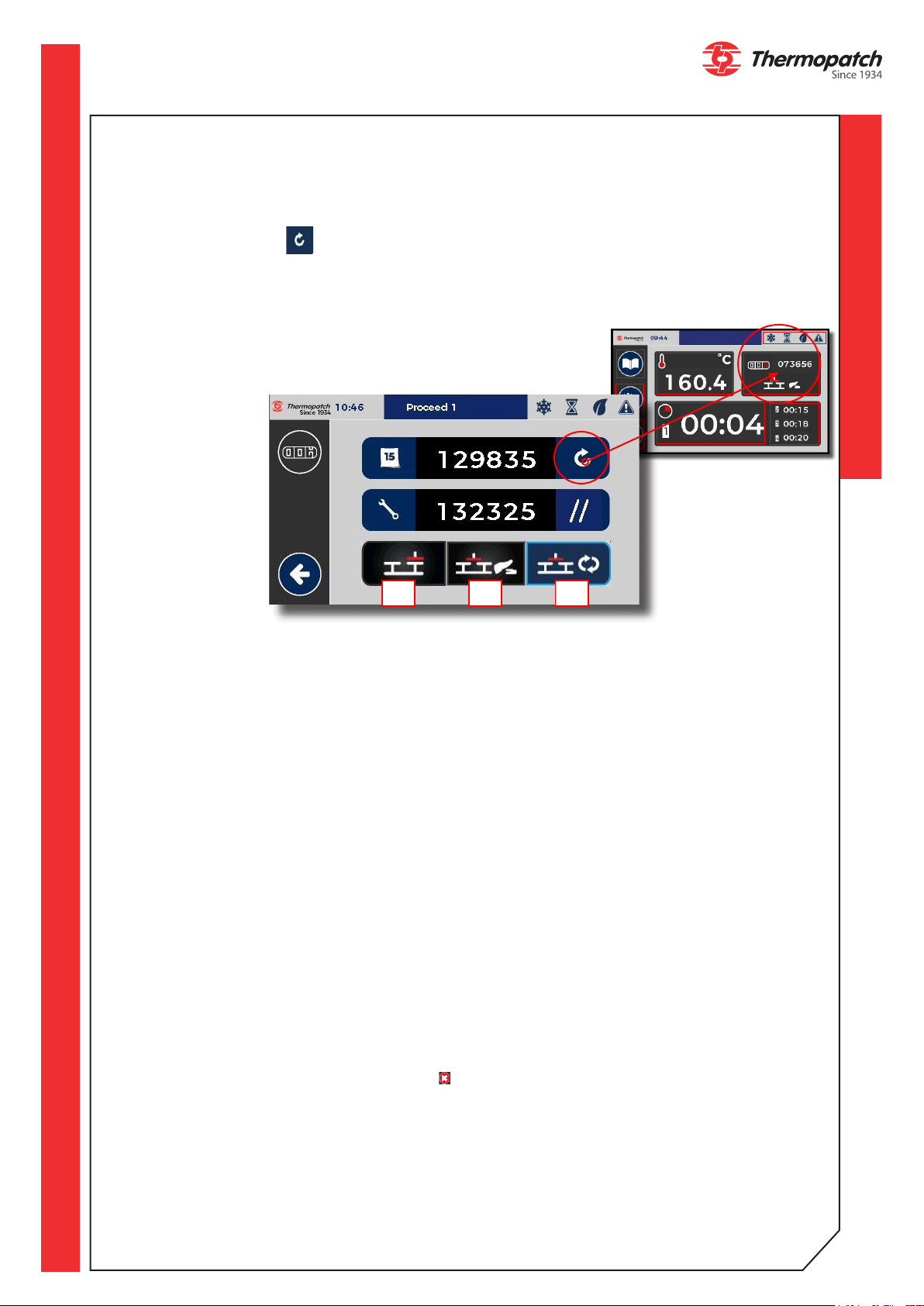
4.2.3.3 Presets
The system is designed to receive up to 6 dierent presets. Each preset can be renamed
with 16 characters. You can access the set-up page for presets and preferred settings as fol-
lows:
In the presets you can store:
• The name of the preset
• The type of control (3 types:
for textile (TEXTILE), for
rigid material sublimation
(RIGID) and drying of pretreatment on textiles (DTG).
• 4 dierent timers
Proceed 1
These values are summarized
on this screen.
The following controls are available for each type of product:
TEXTILE: silkscreen printed transfers, digital transfers, emblems, plotter foils
RIGID: Sublimation of rigid materials
DTG: Drying of pretreatment on textiles
thermopatch.com
13

In order to leave this screen, you must rst save the preset (A), even if there has not been
any change.
The Exit button (B), bottom left on the screen, appears so you can leave this screen.
AB
4.2.3.4 Settings menu and diagnosis
• Push the button on the left of the screen to access the settings.
• Click on the desired menu to access it.
• Press the arrow on the bottom right to get out.
Settings (buzzers,
timers, etc.)
Proceed 1
Time settings
Eco Modes
2 pages
Firmware
information
thermopatch.com
Diagnosis (I/O,
warnings etc.)
Protected
access
14

4.2.3.5 Ergonomic settings
1 3
2
4
8
5
1. Buzzer ON/OFF = Disables or activates the buzzer when touching the screen and at the
end of the cycle. The buzzer remains operational in the event of a fault (5x buzzing).
2. Buzzer « End of cycle » ON/OFF = buzzing for 2 seconds before the end of the cycle.
3. Access to the page "Rotation - temperature range"
4. Unit change : allows to change temperature unit (° Celsius or ° Fahrenheit)
5. Selection for the amount of timers: 3 positions => a single timer, 2 timers or 4 dierent
timers and congurable.
6. Switching delay: In auto mode, wait for rotation of the press arm before the next cycle
(settable in seconds and tenths of a second).
7. Operating temperature range of the machine: allows the start of the cycle to be con-
trolled when the temperature has not yet been reached or exceeded.
a. Minimum : from -30 to 0°C or from -86 to 0°F.
b. Maximum : from 0 to 30°C or from 0 to 86°F.
8. Back to Menu
4.2.3.6 Energy mode
6
7
The energy mode has two settings: a long standby setting and a short standby setting.
The long standby mode puts the machine into hibernation for the time dened by the two
parameters. The temperature is then turned o, it will drop to room temperature. (No en-
ergy consumption).
If the machine is in automatic mode, it stops at the set time.
The program displays the idle page to indicate that it is paused. The brightness decreases
and oscillates slightly. This mode also allows an early start of the heating, for example before taking station. For this, it is necessary to leave the machine powered on.
thermopatch.com
15

1
4
8
3
2
(1) Extended standby mode ON / OFF.
(2) Setting the sleep time.
(3) Setting the heating time.
(4) Next page: short sleep.
(5) Short standby mode ON / OFF.
(7) Short standby temperature.
a. Minimum: 40 ° C or 104 ° F.
b. Maximum: 140 ° C or 284 ° F.
(6) Displays the time after which the machine enters standby mode if there has been no activity with the control panel, foot switch, or two-hand operation.
(8) Return to the previous screen.
5
7
8
6
Short standby will lower the temperature after a time of inactivation (no cycle, no touch on
the screen). The program displays the idle page to indicate that it is paused. The brightness
decreases and oscillates slightly.
Regarding the temperature, in eco mode, it is impossible to ask for a lower temperature
than the set point of the current recipe.
In standby mode, it is impossible to ask for a temperature higher than the temperature of
the eco mode.
To exit the energy saving modes in progress, a touch on the screen is sucient and deactivates the mode (button (5) on "O").
thermopatch.com
16

4.2.3.7 Time and date
1
2
4
1. Set the time format
2. Set the time value
3. Set the date value
4. Set AM or PM
5. Back to MENU
3
Procedure to set the date:
• Choose format
• Set time
• Set date
• Check values
• Back
4.2.3.8 Information
Manufacture / rmware version
thermopatch.com
17

4.2.3.9 Factory settings
Change the factory settings for the machine.
Enter the password in the dedicated eld:
ATTENTION!
Changing the factory settings voids the warranty of the machine.
Additional protected
access
Oset setting
Factory setting
thermopatch.com
18

5. Diagnosis
This screen is only for information on the status of the inputs and outputs of the PLC (Programmable Logic Controller).
On this screen all operating cycles are possible by pressing the footswitch and the green
buttons.
To leave the screen, press .
This screen is used for troubleshooting and evaluating sensor - and actuator states. The
technical support service can ask the operator to display it during assistance by telephone,
for example.
1. Inputs
2. Outputs
3. Temperature in ° Celsius or ° Fahrenheit
4. Analogue value of the static relay (resistance control) (0 to 1000 pts)
5. Active SFC Step: number of the active steps during the cycle (0 to 10)
6. Totalizer counter (no reset)
7. Active mode: FULL AUTO, SEMI AUTO, 1 Station
8. Alarm in progress: access summary page alarms
9. PID control type (based on PID values)
10. Change plate and stop cycle button
11. Back to previous page
1 3 4 5
10
11
5.1 Alarms and warnings
If a fault is detected, the machine is in STOP (
Following screen is diplayed :
2
7968
)mode
thermopatch.com
Press the red area on the touchscreen to conrm the fault and the job page will be displayed.
19

If an incident is detected, the machine is put on hold ( ).
Press the orange part on the touchscreen to conrm the fault and the job page will be displayed.
If the incident is not conrmed, this screen will remain in place. To exit this screen, press
the 'back' symbol, to see which incident is still present on the list of activated alarms and if
shown, press the ashing triangle in this list.
1. Blinking indicator for active fault
2. Access to the Default page (ashin LED)
3. Back to MENU
1
3
2
5.2 Summary alarms and incidents
If the problem that caused the fault (faulty sensor, lack of air, temperature problem) is
solved, the fault indicator (
thermopatch.com
: Removes unpaid defects that are no longer in progress (repair done).
) goes out automatically.
If this support is not enough, stop and restart the machine (press the emergency stop).
20

5.2.1 List of alarms and incidents
Active Fault Inactive Fault
Alarm 00 : PT100 sensor
Alarm 01 : Overheat
Temperature over 220°C
Alarm 02: Plate security
activated
Alarm 03 : Temperature
regulation issue (Static
relay or other)
Alarm 05 : Press cylinder's upper sensor is not
reached
Loss of signal from the sensor (sensor
or cable). The heating control is instantly deactivated.
Temperature is over 220°C. The heating regulation is instantly deactivated.
The detection is immediate. Heating
control and pressing are instantly deactivated.
Indicates the abnormal dierence between the activation of the analog output and the delta of the corresponding
temperature. (Cable, resistance or
static relay problem).
Signal not detected after 5 seconds.
Result of sensor failure, lack of compressed air supply, mechanical lock,
...).
Alarm 06 : Press cylinder's lower sensor is not
reached
Alarm 8 : Right sensor
of the rotation cylinder is
not reached
thermopatch.com
Signal not detected after 5 seconds.
Result of sensor failure, lack of compressed air supply, mechanical lock,
...).
Signal not detected after 5 seconds.
Result of sensor failure, lack of compressed air supply, mechanical lock,
...)
21

Alarm 08: Left sensor of
the rotation cylinder is
not reached
Alarm 10: Temperature
setpoint not reached.
Alarm 11: Change of
temperature unit (Celsius
or Fahrenheit)
Alarm 12 : Maintenance
required
Alarm 13 : Sensors left
or right have not been
reached. Movement impossible.
Signal not detected after 5 seconds.
Result of sensor failure, lack of compressed air supply, mechanical lock,
...)
The temperature trips during rise or
fall before + or - 30 ° C around the
set point. An extra push on green Button and / or the footswitch within a
minute will start the press cycle
Appears when you change the unit of
temperature. Prevents the operator
from unwanted temperature unit selection.
unavailable
It activates when the operator presses
the footswitch or the green buttons
while the pressarm is not above one of
the plates.
Alarm 14 : PLC battery
End of life (shelf life: 7 years at 20 °
C)
6. Operating Cycle
The NL-33 Auto Maxi can operate through 3 cycle variants:
Semi-automatic footswitch mode: after pressing the footswitch, the press arm changes po-
sition and performs a heat sealing cyle.
Single station mode: after pressing the footswitch, the press arm changes position, presses
and returns back to its starting point.
Automatic mode: after pressing the footswitch, the press arm changes its station and
presses. At the end of the countdown of the "timer after pressing", it automatically changes
position and presses again. This automatic cycle will continue until interrupted by pressing
the STOP icon (
thermopatch.com
control buttons.
), pressing the footswitch or pressing the any one of the green bi-manual
22

6.1 Number of timers
It is possible to choose a single timer, two timers or four dierent congurable timers.
When you set 2 or 4 timers, the rst timer can operate over the left or right tray.
• It will keep this position as long as one does not stop voluntarily or by the appearance of
an alarm-event.
• At the next cycle start, the next timer will be the rst.
• Each separate timer is not linked to the working position.
thermopatch.com
23

7. Overview of safety measures and
warnings
7.1 Safety
The NL-33 is equipped with all mandatory safety requirements that apply according to the
European guidelines for machine safety.
The safety frame
The heating element of the NL-33 is shielded with a safety rack. This is to prevent the risk
of pinching during heat sealing.
The emergency stop button
As required in the guidelines for machines, the machine is provided with an emergency stop
button. Press in case of emergency!
Turn the knob counter-clockwise to unlock again and the machine will reset automatically.
Two-hand control
For added safety, the machine is tted with a two-hand control. In order to be able to operate the machine by hand it is required to press both green buttons, placed on the left and
right side op the press arm, simultaneously. This prevents hands and ngers being pinched
between both plates.
thermopatch.com
24

Warning symbols:
for additional safety the following symbols have been placed on the machine:
WARNING!
Hot surface
WARNING!
Electrical voltage
ATTENTION!
Make sure you are informed about the contents of this manual before starting to work
with the NL-33. This ensures an optimal and safe use of the machine.
ATTENTION!
Always turn the power o (unplug it) when you need to carry out maintenance work or
when
cleaning the machine.
ATTENTION!
In case of emergency, press the emergency stop button!
ATTENTION!
Take care that there is enough space around the machine. Cables and connections must
not get pinched. Although the heat radiation of the press is low, there should be
enough space for cooling down.
ATTENTION!
Avoid contact with the press and the heating element.
Pull the fabrics tight around the lower platen and ensure that your hands are away
thermopatch.com
ATTENTION!
from the machine before operating the machine
25

8. Technical specications
8.1 Specifications of the NL-33 Auto Maxi
Energy consumption 3200 Watt
Connection voltage 220-240 Volt 50/60 Hz
Temperature adjustable up to max: 255°C (+/- 1%)
Height (open) 713 mm
Width 1071 mm
Depth (with connections) 1005 mm
Net weight 153 kg
Dimensions of the press cushions 400 x 500 mm
Fuses 2 x T 16A 250 V
A -weighted sound pressure < 70 dB(A)
Compressed air consumption @ 4 bar 3.19 L/cycle
Compressed air consumption @ 6 bar 4.78 L/cycle
Compressed air consumption @ 8 bar 6.37 L/cycle
Prepressure > 3,5 bar - 8 bar
Maximum pressing force 925 DaN
thermopatch.com
26

8.2 Overview
Touchscreen
Manometer
Connector
heating plate
Cover + electronic
board
Pressure
setting
Emergency
stop button
Air pressure inlet
and air lter
Footswitch
Plug and fuse box
Autoswing cilinder
Heating plate with
safety frame
thermopatch.com
2x exchangeable seal-
ing plates with sili-
cone rubber
cushions
27

9. Transport and storage
9.1 Transport
When the machine has to be moved, Thermopatch recommends to use the original
packaging.
9.2 Storage
If the machine has to be stored, Thermopatch recommends to use the original packaging.
The machine must be stored o the ground, preferably on a pallet in dry conditions.
thermopatch.com
28

10. Technical Manual
10.1 Maintenance
Make sure that the working cycle of the machine has ended before you start working on the
machine. Depending on the work to be performed, the power supply or the air supply can
be disconnected.
The air cylinder and other parts of the machine are virtually maintenance-free.
However, the condition is that clean and dry air is used for the heat seal machine. The applied water separator / pressure regulator is an extra safety.
Have your machine serviced by technically qualied personnel. Moisture and polluted air
disturb the sustainable lubrication of the air cylinder.
It is recommended to have the following tools at hand:
• Phillips and at screwdrivers
• A set of at and pipe keys
• Allen key set
• A multimeter
ATTENTION!
Remove the plug from the wall socket BEFORE starting maintenance or repairs
Teon cover:
The teon lm protecting the element must be cleaned regularly to prevent sticking of labels and patches or the transfer of dirt to the garments. Clean the Teon cover with a dry,
clean cloth while the machine is still warm. Repeat the process regularly as often as neces-
sary. Damaged or soiled Teon protection should be replaced. These are available from your
Thermopatch supplier.
Rubber cushion:
Clean the still warm rubber plate with a clean, lint-free cloth. Clean it as often as necessary.
Damaged or soiled rubber sheets must be replaced. These are available from your Thermopatch supplier.
Replacing the rubber cushion:
• Turn o the device and allow it to cool
• Make sure both the bottom metal plate and the rubber cushion are clean and free of
grease
• Apply SPA-AS1504 silicone adhesive (with a glue comb) to the metal plate and place the
rubber plate immediately with no air bubbles
• Allow to dry overnight at room temperature under light pressure without heating.
Air lter:
The air lter, or the water separator / pressure regulator, must be checked daily and, if necessary, emptied by opening the cap on the underside of the lter.
Replace the fuses
Make sure that the machine is switched o and that the power cord is unplugged! Replace
the T16 A fuses at the back of the machine. Then plug in the power cord again and the machine is ready for use again.
For other parts, contact your supplier for their replacement or repair.
thermopatch.com
29

10.1 Replacement parts list
Reference Description Quantity
ELECTRICAL PARTS
CAR-CO2 CONTROL BOARD 1
SPA27-005 MICA HEATING ELEMENT 400x500 2500W 1
SPA3X-024 TEMPERATURE PROBE 1
SPA3X-003 FUSE 5 x 20 mm T 16 A 250 V 2
PNEUMATIC PARTS
VER-SM29 CYLINDER Ø100 C50 1
FIL-013 AIR FILTER 1
ELE-SM3 SOLENOID CONTROL VALVE 5/2 G1/8 12V 1
TEFLON and SILICONE RUBBER
SPA3X-100-7 FOAM 9.53 mm 400 x 500 1
SPA3X-019 TEFLON SHEET 1
10.2 Troubleshooting
Problem Possible cause Solution
The machine
does not
switch on
• The plug is not connected
• The switch is not connected
• The emergency stop button is activated
• The display is faulty
• Check your network and if the machine
is connected to it.
• Set the main ON / OFF switch to 1.
• Turn the red knob to unlock the emergency stop button
• Check that the cables are not damaged (possible short circuit)
The machine
is not heating
up
The heating element
overheats
The timer
does not
count down
The press
head does
not lower
The press
head does
not come up
The press
head stays
down after
thermopatch.com
pressing
• Faulty heating element
• Problem with the main
board
• Temperature is set too
low
• Problem with the temperature sensor
• Disabled or faulty cylinder sensor
• Problem with the electronic board
• The control buttons are
not working
• Leaking cylinder
• Too low pressure on air
supply
• Faulty solenoid control
valve
• Leaking cylinder
• The timer is not counting
down
• No compressed air provided.
• Check the connections and the condition of the wiring
• Remove the heating element
• Check the on-screen messages and
refer to the section error messages,
page 20-21
• Check de messages on the LCD
screen, page 20-21
• Contact your supplier
• Check the connections
• Check the on-screen messages and
refer to the section error messages,
page 20-21
• Check the connections
• Check the seals and all connections,
contact your supplier
• Check the valve couplings, contact
your supplier for replacement
• Check that the air supplied is above 3
bar
• Check the valve couplings, contact
your supplier for replacement
• Check the seals and all connections,
contact your supplier
• See above
30

Press Cylinder
Pressing Electrical
Distributor
Cylinder stopper
mounted on the
cylinder bottom
port
Rotation Electrical
Distributor
Rotation regulator
Pneumatic net-
work connection +
Filter
(mounted on the
outside)
Rotation cylinder
thermopatch.com
Rotation cylinder on the back of the machine
Inside the press arm
Left sensor
Right sensor
31

Limit switch
up
Connector
block
24V DC
0 VDC
Press
cylinder
Limit switch
down
Buzzer
Green bi-manual
control buttons
on the side of the
press arm
Manometer
Emergency
stop
button
The front panel
tilts forward,
leaving the two
screws
Opening the front panel
Rotation
regulator
USB cable
connector
(not included)
thermopatch.com
PLC-HMI
Inside the top cover
32

Laser option
power supply
220 VAC
Footswitch
connection
Power supply
220 V/24 V
Reheating
plate static
relay
Security
Relay
Protection
fuse
24 VDC
220 VAC
thermopatch.com
33

10.4 Electrical wiring diagram
ELECTRIC
DIAGRAM
Thermopatch B.V. Draaibrugweg
14, 1332 AD Almere, Netherlands
NL-33
NL-33 Auto Maxi
THERMOPATCH
thermopatch.com
34

10.5 Pneumatics diagram
NL-33 Auto Maxi
THERMOPATCH
thermopatch.com
35

11. End of life
Choose to dispose of the machine responsibly when it has reached its end of life.
Electrical machinery, accessories and packaging should be recycled as much as possible in
an environmentally responsible manner.
- Dismantle the machine groups: steel parts / pneumatic components / electrical components
- These can be separated and returned for recycling.
ATTENTION!
Always dispose according to current and locally applied guidelines for health and
safety and disposal requirements.
thermopatch.com
36

12. Declaration of conformity
We,
Thermopatch B.V.
Draaibrugweg 14
1332 Almere
Netherlands
Declare under our own responsability that the heat sealing ma-
chine:
Thermopatch NL-33 Auto Maxi,
which this declaration refers to, is in accordance with the condi-
tions of the following Directive(s):
2014/30/EU (emc directive)
2006/42/EG (machinery directive)
Netherlands, Almere, 01-02-2019
Jan Bausch,
Director
thermopatch.com
37

13. Disclaimer
The information contained in these documents is condential, privileged and only for the
information of the intended recipient and may not be used, published or redistributed
without the prior written consent of Thermopatch B.V.
The opinions expressed are in good faith and whilst every care has been taken in preparing these documents, Thermopatch B.V. makes no representations and gives no warranties
of whatever nature in respect to these documents, including but not limited to the accuracy or completeness of any information, facts and/or opinions contained therein.
Thermopatch B.V., its subsidiaries, the directors, employees and agents cannot be held li-
able for the use and reliance of the opinions and ndings in this document.
For any warranty Thermopatch B.V. refers to its general terms and conditions.
We can conrm that the machines we supply conform to CE when in standard conguration.
Using sealing plates and pads of any format other than the standard supplied with the machine may render the CE declaration invalid.
Thermopatch accepts no responsibility for any damage or injury that may result from possible non-conformity.
Choosing an alternative conguration other than the standard is at the customer’s own
responsibility.
thermopatch.com
38

Thermopatch Corporate Headquarters USA T +1 315 446-8110 F +1 315 445-8046 sales@thermopatch.com
Thermopatch European Headquarters The Netherlands T +31 36 549 11 11 F +31 36 532 03 98 sales@thermopatch.nl
Thermopatch Australia Pty Ltd Australia T +61 395325722 F +386 2 80 55 232 marktpatchaust@bigpond.com.au
Thermopatch Canada Inc Canada T +1 519 748-5027 F +1 519 748-1543 broussel@thermopatch.com
thermopatch.com
 Loading...