

Instruction Manual
Models 135A and 136S
Waterproof and Intrinsically Safe
Portable Conductivity Meters

Software V ersion: 1.x
TA–193.204–ORE02 260201
AQUAfast, Cahn, ionplus, KNIpHE, ORION, PerpHecT, perpHecTion, Sensing the future, SensorLink, Sure-Flow, Titrator PLUS and TURBO2 are registered trademarks of Thermo Orion.
1-888-pHAX-ION, All in One, AssuredAccuracy, AUTO-BAR, AUTO-CAL,
AUTO DISPENSER, AUTO-LOG, AUT O-STIR, AUT O-READ, Cable-Free,
CERTI-CAL, CISA, DataCOLLECT, digital LogR, DirectCal, DuraProbe,
Extra Easy/Extra Value, F AST QC, GLPcal, GLPcheck, GLPdoc, Ionalyzer,
KAP, KNIpHE, LogR, Minimum Stir Requirement, MSR, NISS, One-Touch,
One-Touch Calibration, One-Touch Measurement, Optimum Results, PENPal, pHISA, pHix, Phuture, Pure Water, QuicKcheK, rf link, ROSS, ROSS
Resolution, Sage, SAOB, Stat Face, The Enhanced Lab,ThermaSense,
Triode, TRIUMpH, Unbreakable pH, Universal Access and Wine Master are
trademarks of Thermo Orion.
Guaranteed Success and The Technical Edge are service marks of
Thermo Orion.
PerpHecT meters are protected by U.S. patent 4,321,544. Other patents
pending.
ROSS and PerpHecT ROSS are protected by U.S. patent 4,495,050. Other
patents pending.
ORION Series A meters and 900A printer are protected by U.S. patents
5,108,578, 5,198,093, D334,208, D346,753.
ORION 81, 82, 91, and 92 series glass electrodes are protected by U.S.
patents 4,661,236 and 4,687,500.
Sure-Flow electrodes are protected by European patent 278,979 and Canadian patent 1,286,720. Other patents pending.
ionplus electrodes and Optimum Results solutions have patents pending.
E Copyright 1999, Thermo Orion. All rights reserved.
The specifications, descriptions, drawings, ordering information and part
numbers within this document are subject to change without notice.
This publication supersedes all previous publications on this subject.

Models 135A and 136S Portable Conductivity Meters
Information III
Safety Precautions
Be sure to read and follow these instructions !
The Model 136S Conductivity Meters may only be opened
to change the batteries outside hazardous areas. If repairs
are necessary, the meter must be sent in to the factory.
Never operate the remote interface or printer within hazardous areas.
When using the meter in hazardous areas, watch for electrostatic charges! For example, never wipe off the meter
with a dry cloth. Observe the relevant regulations concerning ESD.
Whenever it is likely that the protection has been impaired, the meter shall
be made inoperative and secured against unintended operation.
The protection is likely to be impaired if, for example:
❏ the meter shows visible damage
❏ the meter fails to perform the intended measurements
❏ after prolonged storage at temperatures above 70 °C
❏ after severe transport stresses
Before recommissioning the meter, a professional routine test according to
EN 61 010-1 shall be performed. This test should be carried out at our factory.
cal
Note
Warning
Information IV
Information on this Instruction Manual
ITALICS are used for texts which appear in the display of
Thermo Orion Model 135A or 136S.
Bold print is used to represent keys, e.g. cal.
Display examples
or
keys whose functions are explained are frequently shown
in the left-hand column.
Notes provide important information which should always
be observed when using the meter .
Warning means that the instructions given must always be
followed for your own safety. Failure to follow these
instructions may result in injuries.

Models 135A and 136S Portable Conductivity Meters
Contents V
Contents
Safety Precautions III. . . . . . . . . . . . . . . . . . . . . . . . . . . . . . . . . . . . . . . . . . . . .
Information on this Instruction Manual IV. . . . . . . . . . . . . . . . . . . . . . . . . .
1 The Models 135A and 136S Conductivity Meters 1. . . . . . . . . . . . . . .
Package Contents 1. . . . . . . . . . . . . . . . . . . . . . . . . . . . . . . . . . . . . . .
Short Description of Meters 1. . . . . . . . . . . . . . . . . . . . . . . . . . . . . . .
2 Operation 3. . . . . . . . . . . . . . . . . . . . . . . . . . . . . . . . . . . . . . . . . . . . . . . . . .
Meter Design 3. . . . . . . . . . . . . . . . . . . . . . . . . . . . . . . . . . . . . . . . . . . .
Display 4. . . . . . . . . . . . . . . . . . . . . . . . . . . . . . . . . . . . . . . . . . . . . . . . .
Keypad 4. . . . . . . . . . . . . . . . . . . . . . . . . . . . . . . . . . . . . . . . . . . . . . . . .
Connection and Start-up 6. . . . . . . . . . . . . . . . . . . . . . . . . . . . . . . . . .
Configuration 8. . . . . . . . . . . . . . . . . . . . . . . . . . . . . . . . . . . . . . . . . . . .
Calibration 11. . . . . . . . . . . . . . . . . . . . . . . . . . . . . . . . . . . . . . . . . . . . . .
Measurement 15. . . . . . . . . . . . . . . . . . . . . . . . . . . . . . . . . . . . . . . . . . .
Data Log Memory 17. . . . . . . . . . . . . . . . . . . . . . . . . . . . . . . . . . . . . . . .
Data Log 18. . . . . . . . . . . . . . . . . . . . . . . . . . . . . . . . . . . . . . . . . . . . . . .
Clock Mode 20. . . . . . . . . . . . . . . . . . . . . . . . . . . . . . . . . . . . . . . . . . . . .
Serial Interface 21. . . . . . . . . . . . . . . . . . . . . . . . . . . . . . . . . . . . . . . . . .
Standard Setting for PRT300 Printer 22. . . . . . . . . . . . . . . . . . . . . . .
Configuring the PRT300 Printer 22. . . . . . . . . . . . . . . . . . . . . . . . . . . .
Printing Measured Values and GLPdoct Report 23. . . . . . . . . . . . .
3 Troubleshooting and Maintenance 24. . . . . . . . . . . . . . . . . . . . . . . . . . .
Error Messages 24. . . . . . . . . . . . . . . . . . . . . . . . . . . . . . . . . . . . . . . . .
Maintenance 27. . . . . . . . . . . . . . . . . . . . . . . . . . . . . . . . . . . . . . . . . . . .
Changing batteries 27. . . . . . . . . . . . . . . . . . . . . . . . . . . . . . . . . . . . . .
Cleaning the meter 28. . . . . . . . . . . . . . . . . . . . . . . . . . . . . . . . . . . . .

Contents VI
Appendix 29. . . . . . . . . . . . . . . . . . . . . . . . . . . . . . . . . . . . . . . . . . . . . . . . . . . . . .
Declarations of Conformity 29. . . . . . . . . . . . . . . . . . . . . . . . . . . . . . . .
Certificate of Conformity 31. . . . . . . . . . . . . . . . . . . . . . . . . . . . . . . . . .
Control Drawing 33. . . . . . . . . . . . . . . . . . . . . . . . . . . . . . . . . . . . . . . . .
Ordering Information 35. . . . . . . . . . . . . . . . . . . . . . . . . . . . . . . . . . . . .
Specifications 39. . . . . . . . . . . . . . . . . . . . . . . . . . . . . . . . . . . . . . . . . . .
Specifications for PRT300 Printer 40. . . . . . . . . . . . . . . . . . . . . . . . . .
Warranty 41. . . . . . . . . . . . . . . . . . . . . . . . . . . . . . . . . . . . . . . . . . . . . . .
Technical Terms 44. . . . . . . . . . . . . . . . . . . . . . . . . . . . . . . . . . . . . . . . . . . . . . . .
Index 46. . . . . . . . . . . . . . . . . . . . . . . . . . . . . . . . . . . . . . . . . . . . . . . . . . . . . . . . . .
Models 135A and 136S Portable Conductivity Meters
Models 135A and 136S 1
1 The Models 135A and 136S
Conductivity Meters
Package Contents
Please check the completeness of the shipment after unpacking.
The package should include:
❏ Thermo Orion Model 135A or 136S Conductivity Meter
(ready for operation)
❏ Neck strap
❏ This instruction manual
❏ Quickstart instructions
❏ Interface cable with adapter for printer and PC
❏ PC software
Short Description of Meters
❏ The Models 135A and 136S measure conductivity, sali-
nity, TDS and temperature in industry, the environment,
food processing and waste-water treatment.
❏ Operation of the Model 136S is also permitted in Zone 1
hazardous areas.
❏ The meters meet the European EMC regulations
(89-336-EEC) and the recommendations of NAMUR
NE 21.
❏ The meters are IP 66 protected to EN 60 529.
Warning
Models 135A and 136S 2
❏ T emperature compensation is automatic with a conducti-
vity probe with integral temperature sensor or a separate ATC probe, or the temperature may be manually
entered.
❏ Calibration can be carried out by directly entering the
cell constants, by calibrating with Thermo Orion Conductivity Standards, or with any other buffer solutions.
❏ The data log records up to 100 measured values with
the temperature, date and time. Recording takes place
either manually, interval or event-controlled.
❏ To minimize battery consumption, the meter switches off
after either one or twelve hours when it is not operated.
❏ Only three alkaline AA batteries are required for uninter-
rupted operation for approx. 1,000 hours.
❏ PC software allows complete remote control of the me-
ter via PC. All measured values and parameters can be
read out and easily processed further (e.g. using Microsoft Excel).
❏ Measured values and GLPdoct can also be sent di-
rectly to a printer via the serial interface.
Never use the remote interface to PC or printer in hazardous areas!
Models 135A and 136S Portable Conductivity Meters
Operation 3
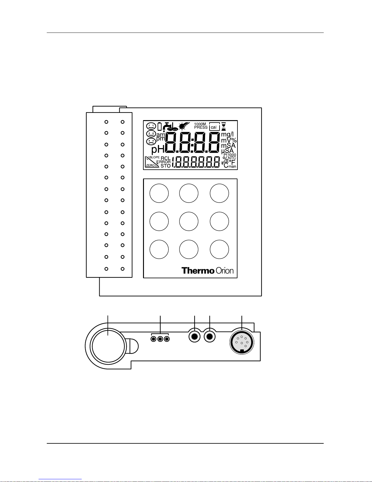
2 Operation
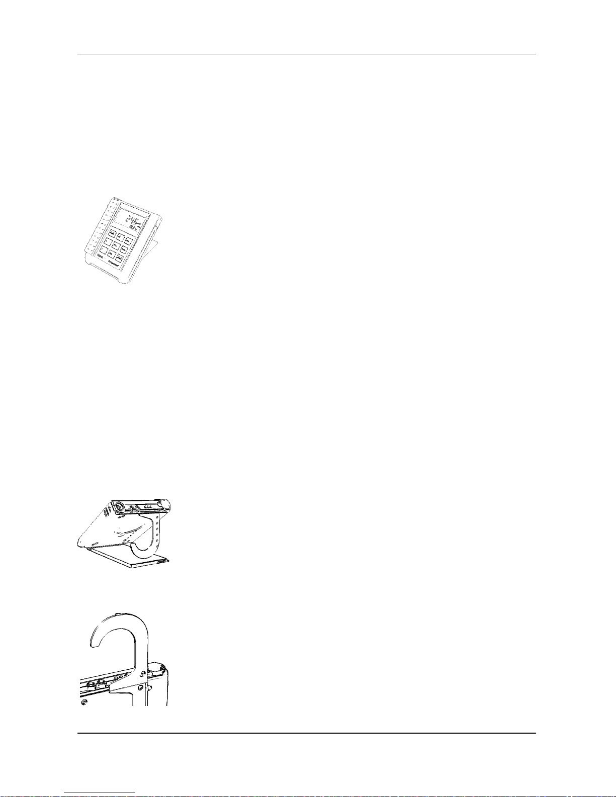
Meter Design
1
2
3
4
5
1 Sensor connection
2, 3 Separate temperature probe connection
4 PC/printer interface connection
5 Probe holder , removable
meas
cal
STO
RCL
Y
B
print
clock
power
power
meas
Note
cal
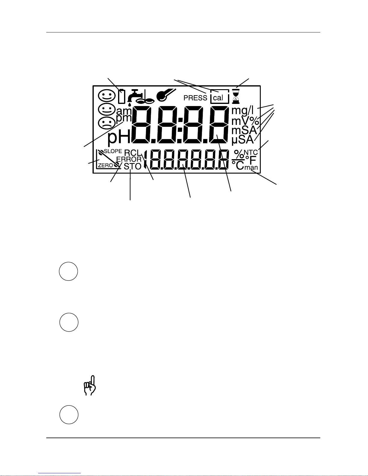
Operation 4
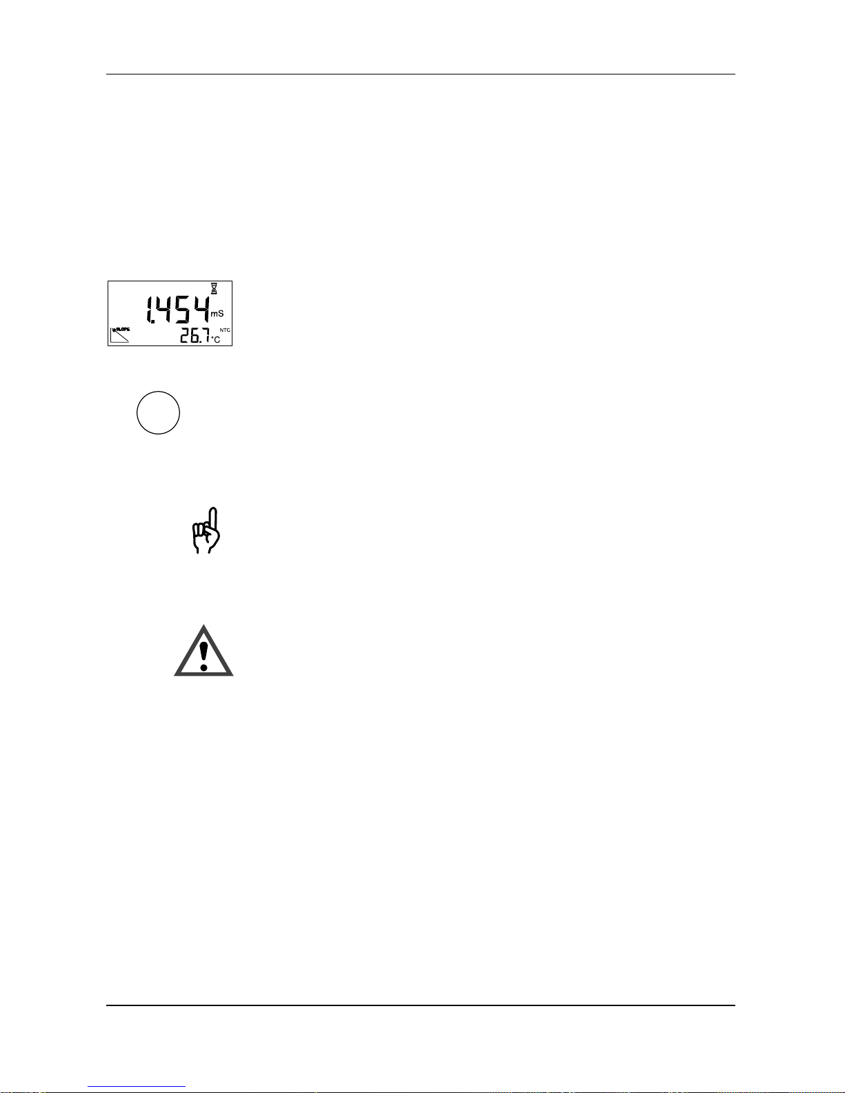
Display
Battery
empty
Press
cal key
Wait
Manual
temperature
detection
Temperature
detection
using NTC
Write
memory
Read
memory
Slope
(cell
constant)
Clock
Main
display
Secondary
display
Measurement units
Error
message
Keypad
Pressing the power key switches the meter on or off.
After switching on, the meter automatically performs a
self-test and checks for the presence of a temperature
probe. Then it goes into the measuring mode.
Pressing the meas key returns the meter to the measuring mode from any function. Pressing the meas key in the
measuring mode displays the following parameters:
Cond measuring mode: temperature compensation
tdS measuring mode: TDS factor
You can also power the meter up using the meas key.
However, only an abbreviated self-test is performed.
Pressing the cal key starts calibration.
Y B
clock
STO
RCL
print
RCL
+
print
cal
+
print
STO
+
clock
STO
+
clock
cal
+
power
Note
Models 135A and 136S Portable Conductivity Meters
Operation 5
With the
Y and B keys you can select and change parame-
ters and select a mode.
Pressing the clock key switches the meter into the clock
mode. All measurement processes are cancelled and the
battery consumption is reduced to a minimum.
Pressing the STO key activates the data logger for writing
measured values.
Pressing the RCL key activates the data logger for reading
measured values.
Pressing the print key sends the currently measured
value to a printer or PC.
Pressing the RCL and print keys prints out the logged
data in memory.
Pressing the cal and print keys prints out the GLPdoct
report.
Pressing the STO and clock keys switches the meter
into the data logger mode.
Pressing the clock and STO keys activates the mode for
setting the date and time.
Pressing the cal and power keys when the meter is
switched off, activates the configuration menu.
When pressing two keys simultaneously, make sure that
the key shown at the left is pressed first.
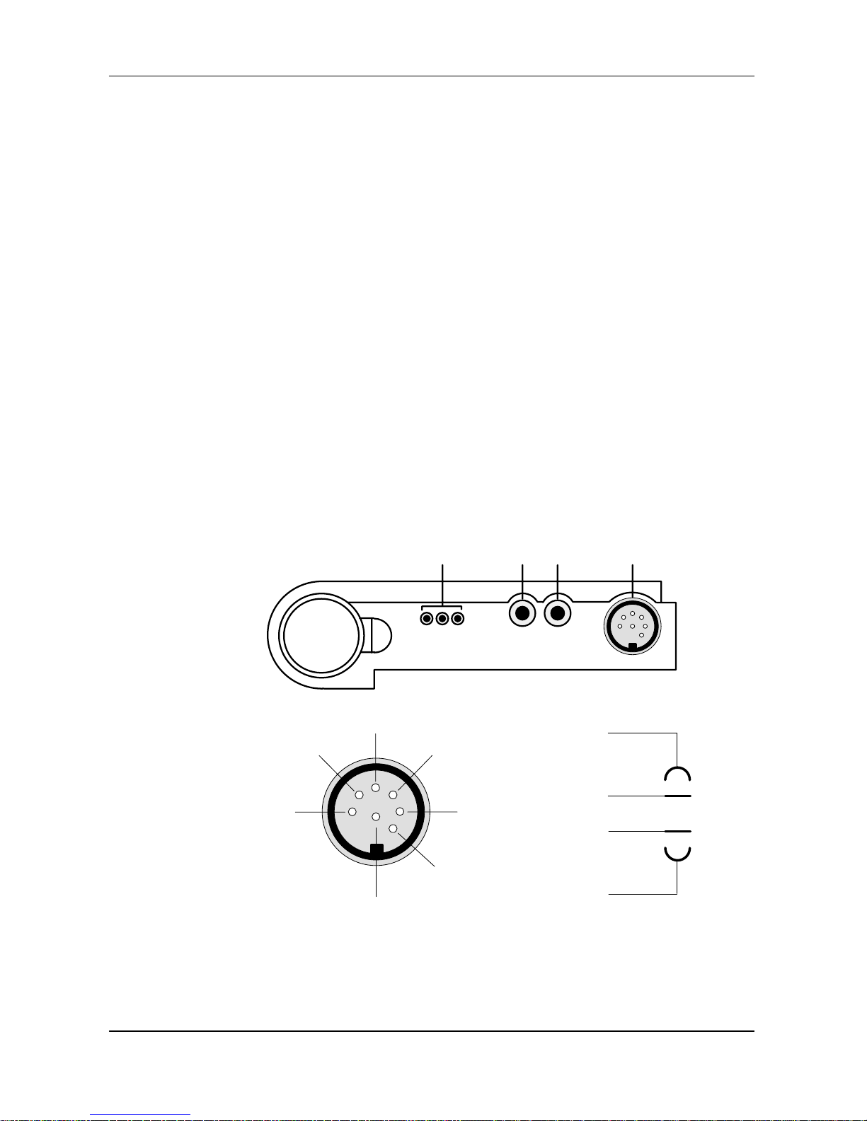
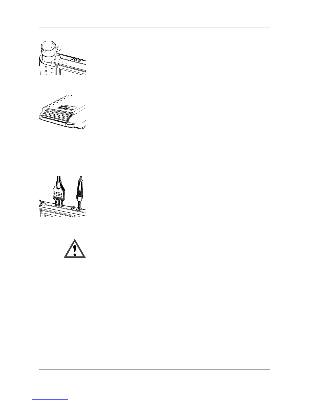
Connecting
sensor
Connection
assignment
Operation 6
Connection and Start-up
The following sensors from the line of accessories can be
connected to the meter .
013610 4-electrode epoxy/graphite sensor
with integrated temperature probe,
3 meter cable
K = 0.55 /cm
013660 4-electrode epoxy/graphite sensor
with integrated temperature probe,
20 meter cable
K = 0.55 /cm
Connection Socket. . . . . . . . . . . . . . . . . . . . . . . . . . .
Sensor 1. . . . . . . . . . . . . . . . . . . . . . . . . . . . . . . . . . . . .
Separate temperature probe 2, 3. . . . . . . . . . . . . . .
Interface 4. . . . . . . . . . . . . . . . . . . . . . . . . . . . . . . . . . .
1234
NTC
V–
V+
I+
Shield
NTC
I–
V+
V–
I–
I+
If no temperature probe is used for measurement, the meter operates with the manually set temperature and man
appears in the display.
Note
Note
Note
Note
power
Note
Note
Models 135A and 136S Portable Conductivity Meters
Operation 7
When using a sensor with temperature probe, an external
temperature probe may not be connected simultaneously.
If the meter is connected to a PC and is used to take measurements in a grounded liquid, measuring errors may
result.
Prior to first use, the cell constant, temperature compensation and time and date must be checked and set, if required.
The calibration and configuration data and the contents of
the data log remain permanently stored both with the meter
switched off and with the batteries removed (battery replacement).
Pressing the power key switches the meter into measuring mode.
When switched on, the meter determines the connected
temperature probe and conducts a self-test:
❏ Simultaneous appearance of all display segments
❏ Display of the model number
❏ Display of the software version
For recognition of the temperature probe, the conductivity
sensor must be connected to the meter before power-up.
The meter can also be switched on with the meas key.
However, only an abbreviated test is performed. The meter
assumes that the last temperature probe determined is
used.
cal
+
power
meas
Function
Operation 8
Configuration
The following basic settings can be changed in the configuration:
❏ Function Cond (conductivity), SAL (salinity) or tdS (Total
Dissolved Solids)
❏ Calibration by entering the cell constants (AutCal Off) or
calibration with Thermo Orion Conductivity Standards
(AutCal On)
❏ Autoshutoff after
1 hour or 12 hours
❏ Remote interface
Printer output On/Off, baud rate
❏ T emperature display
°C or °F
❏ Date and time format
24 hours and day, month, year or
12 hours (a.m./p.m.) and month, day, year
To activate the configuration hold down the cal key with
the meter switched off and then press the power key.
The menu items of the configuration menu are worked
through in sequence. Press the Y or B key to change the
setting of the respective menu item. The STO key saves
the parameters and switches to the next menu item.
Pressing the meas key exits the configuration menu at
any time. The value last displayed will not be saved unless
the STO key was pressed.
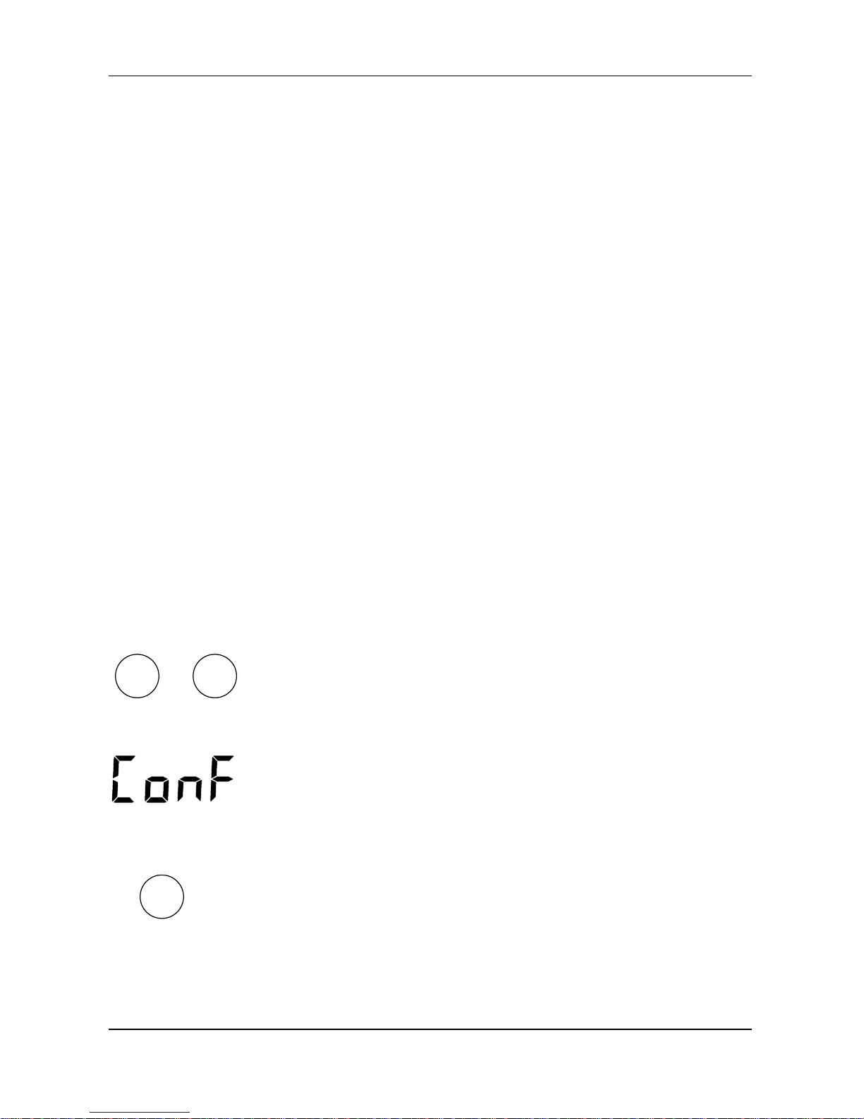
Select the measuring function Cond (conductivity), SAL
(salinity) or tdS (Total Dissolved Solids).
Automatic
or manual
calibration
Autoshutoff
Interface
Models 135A and 136S Portable Conductivity Meters
Operation 9
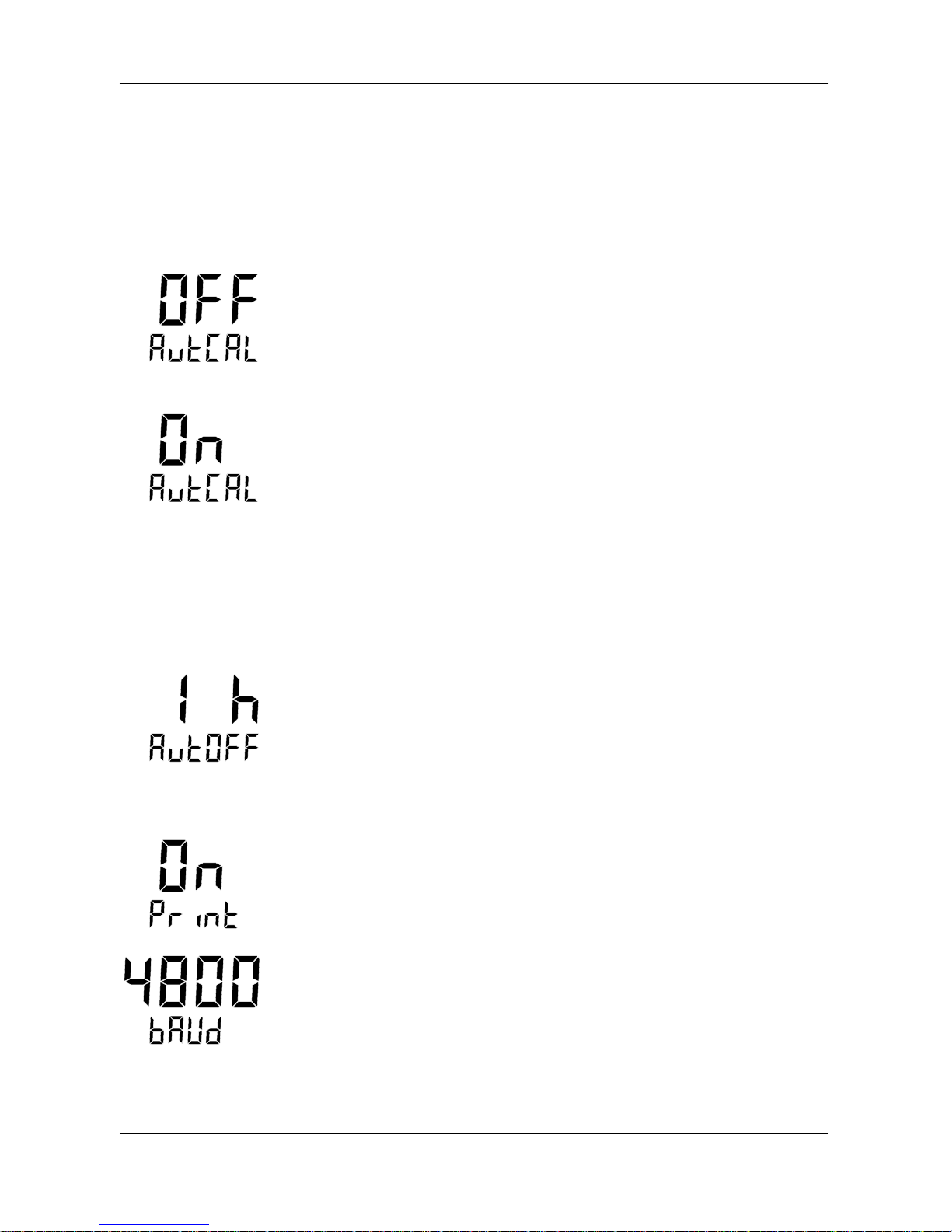
Select whether you wish to manually set the cell constant
or calibrate using Thermo Orion Conductivity Standards
and automatic drift check.
(Default setting: Direct entry of the cell constant [AutCAL
OFF])
Direct entry of the cell constants (AutCal OFF) from
0.010 cm
–1
to 199.9 cm–1.
(Default setting 0.475 cm
–1
)
Automatic calibration (AutCAL On) with 0.1 molar KCl solution (Thermo Orion 12.9 mS Conductivity Standard,
Cat. no. 011006), 0.01 molar KCl (Thermo Orion 1413 mS
Conductivity Standard, Cat. no. 011007) or entry of the
temperature-compensated conductivity of another known
calibration solution.
To protect the batteries, the meter switches off automatically when not operated for a longer time than specified.
You can select whether shut-off is to take place after one
hour or after twelve hours (default setting: 1 hour).
If the data logger is active and during remote interface
operation, the autoshutoff feature is disabled.
If the meter is controlled with a PC and interface conflicts
occur when the print key is pressed, the print function
should be deactivated (Print OFF).
(Default setting: Print On, 4,800 baud)
The transmission speed can be set to 600, 1,200, 2,400,
4,800 or 9,600 baud.
The transmission speed must correspond to that set in the
printer or PC.
The data format and protocol are permanently set to 7 bit,
one stop bit, even parity and XON/XOFF protocol
(NAMUR NE 28).

Temperature
display
Date and
time
format
Operation 10
The temperature can be displayed either in °C or °F.
(Default setting: °C)
You can choose between the display format 24 hours and
day.month.year and the format 12 hours a.m./p.m. and
month.day.year.
(Default setting: 24 hours and day.month.year)

Calibration
solutions
Clean
sensors
Cell constant
4-electrode
sensors
2-electrode
sensors
Models 135A and 136S Portable Conductivity Meters
Operation 11
Calibration
With calibration the Models 135A and 136S are adjusted to
the cell constants of the sensor .
General information on calibration
Solutions for calibration of conductivity meters are unbuffered systems. Care should be taken to use fresh
conductivity standards and to avoid contamination of the
conductivity standard by water droplets adhering to the
conductivity sensor .
Before calibration, make sure that the conductivity sensor
is clean. Residues should be rinsed off with distilled water.
Afterwards, the sensor should be wiped dry and rinsed with
the calibration solution to be used.
The cell constant is determined by the size and geometric
arrangement of the measuring electrodes. It is the characteristic parameter of conductivity sensors. The cell constant changes very little over time.
With 4-electrode sensors the principle of separate current/
voltage electrodes results in virtually no measuring errors
even in the case of partial soiling of the measuring electrodes. However, electrodes completely soiled with insulating coatings cause the measurement to fail.
With 2-electrode sensors for the measurement of low conductivities, e.g. ultrapure water , calibration should be carried out using Thermo Orion 100 mS Conductivity Standard
(Cat. no. 011008).

cal
Operation 12
Calibration by direct entry of the cell constants (AutCAL OFF)
Press the cal key to activate calibration. The cell constant
determined or set during the last calibration is displayed.
Pressing the meas key exits calibration again.
Set the cell constant of the sensor used with the Y and B
keys and confirm with the cal key. Then the meter
switches back into the measuring mode.

Note
cal
Models 135A and 136S Portable Conductivity Meters
Operation 13
Calibration with 0.1 or 0.01 molar KCl solution (AutCAL On)
(Thermo Orion 12.9 mS or 1413 mS Conductivity Standard)
Impurities must always be prevented from getting into the
calibration solutions.
Pressing the cal key activates calibration.
Calibration can be cancelled by pressing the meas key.
Then the cell constant of the last calibration is displayed
briefly.
Select the calibration solution used (CALSoL). A 0.1 and a
0.01 molar KCl solution are available to choose from. Confirm the corresponding solution with the cal key.
Immerse the clean and dry sensor in the calibration solution (also see “Clean sensors”, Pg. 11).
Press the cal key to start calibration. If calibration is not
desired, cancel the process with the meas key.
During calibration the lower line indicates the temperature.
The automatic drift check checks the stability of conductivity and temperature. The hour glass flashes.
When the measured values are stable, the temperaturecompensated table value of the KCl solution is displayed.
The measured conductivity value flashes.
Confirm with the cal key.
The determined cell constant is displayed for a few seconds. Then the meter switches back into the measuring
mode.

Note
cal
Operation 14
Calibration with any calibration solution (AutCAL ON)
Impurities must always be prevented from getting into the
calibration solutions.
Pressing the cal key activates calibration.
Calibration can be exited again with the meas key. Then
the cell constant of the last calibration is displayed briefly.
First confirm any of the 0.1 or 0.01 mol/l KCl solutions
(CALSoL) with the cal key.
Immerse the clean and dry sensor in the calibration solution (also see “Clean sensors” Pg. 11).
Press the cal key to start calibration. If calibration is not
desired, cancel the process with the meas key.
During calibration the lower line indicates the temperature.
The automatic drift check checks the stability of conductivity and temperature. The hour glass flashes.
When the measured values are stable, the temperaturecompensated table value of the KCl solution is displayed.
The measured conductivity value flashes.
See the table of your calibration solution for the conductivity value which belongs to the displayed measuring temperature.
Set the temperature-compensated conductivity in the meter with the Y and B keys, then confirm it with the cal
key.
The determined cell constant is displayed for a few seconds. Then the meter switches back into the measuring
mode.

Measuring
mode
Note
Temperature
compensation
Note
Models 135A and 136S Portable Conductivity Meters
Operation 15
Measurement
Pressing the meas key accesses the measuring mode
from all functions. In the measuring mode the main display
indicates the measured variable and the secondary display
shows the temperature.
If the meter is connected to a PC and measurements are
taken in a grounded liquid, measuring errors may result.
Measuring the conductivity (Cond)
The main display indicates the measured conductivity, the
secondary display shows the temperature.
The instrument offers various temperature compensation
methods. With the meas key and the Y or B key, the
temperature compensation method can be selected and
set:
(tc OFF) No temperature compensation
(tc nLF) Temperature compensation with non-linear characteristic for natural water and ultrapure water (reference
temperature 25 °C). In the secondary display tc also appears.
(tc 0.01 – 9.99 %/°C) Temperature compensation with linear characteristic and definable temperature coefficients
(reference temperature 25 °C). In the secondary display tc
also appears.
When you have selected temperature compensation with
linear characteristic, you can only exit this function or select the nonlinear function when the temperature coefficient
has been set to 0.00.

TDS factor
Note
Manual
temperature
Operation 16
Measuring the salinity (SAL)
The main display indicates the measured salinity in ‰
(parts per thousand), the secondary display shows the
temperature.
TDS determination (TDS)
The main display indicates the concentration of the dissolved solids contributing to the solution conductivity (TDS,
comparable to the evaporation residue) in mg/l, the secondary display shows the temperature.
Pressing the meas key and then the Y or B key sets the
TDS factor within the range 0.40 – 1.00.
The TDS factor depends on the composition of the water
to be tested and must be determined for each water type.
The man indicator signals that no temperature probe is
connected. The meter operates with the manually specified
temperature. The manual temperature can be edited with
the Y and B keys in the Cond measuring mode.

Write
memory
STO
Read
memory
RCL
Clear
memory
STO
clock
Models 135A and 136S Portable Conductivity Meters
Operation 17
Data Log Memory
Up to one hundred measured values can be stored in the
data log memory together with temperature, date and time.
Storage is performed either manually or automatically using the data log. The currently measured parameter (conductivtiy, salinity or TDS) is stored.
Press the STO key. The currently measured value is
shown on the display.
Select any memory location using the Y and B keys.
Press the STO key to store the measured value in the
selected memory location. After storing, the memory location number is automatically incremented and the meter
returns to measuring mode.
Pressing the RCL key displays the last measured values
stored.
Select any memory location using the Y and B keys.
Pressing the RCL key switches between the measured
value and the time/date of storage.
Pressing the meas key returns to the measuring mode.
To clear the entire data log memory , press the STO key to
access memory mode and then press the clock key to
access data log mode. Select Clear (Clr) using the Y and
B keys.
By confirming this with the STO key, the entire memory is
cleared.
If you do not want to clear the data log, press the meas
key to abort the procedure.

Data log
STO
clock
STO
meas
Data logging
modes
Operation 18
Data Log
The data log records up to 100 measured values together
with temperature, time and date. Data storage is performed either manually (at the press of a key), interval or
event-controlled. The data log always stores the currently
measured parameter (conductivtiy, salinity or TDS).
Press the STO key to access the memory mode and then
the clock key to access the data log mode. Now choose
between three different logging modes and the parameter
setting of the data logger using the Y or B keys.
Pressing the STO key confirms the selected mode. In the
Continue and Start mode this also activates the data log.
The current data memory location is shown on the display.
If “Clear” has been selected, all memory locations are
cleared and the meter returns to the measuring mode.
Pressing the meas key ends the data log mode.
After pressing the STO key, logging is continued after the
memory location in which the last measured value was
stored (continue). Press the meas key to end logging.
After pressing the STO key, the entire data log memory is
cleared without starting the data log (clear).
After pressing the STO key, the entire data log memory is
cleared. Storage begins from memory location “00” (start).
Press the meas key to end logging.

Setting
parameters of
the data log
Note
STO
Note
Models 135A and 136S Portable Conductivity Meters
Operation 19
In the parameter setting mode, you select whether data
storage is to be interval, event-controlled or manual.
Press the STO key to access the logging functions.
To select interval-controlled storage of measured values,
press the STO key and set the interval using the Y and B
keys. The interval range is between 5 seconds and 60
minutes. Default time (factory-set) is 2 minutes. After selecting the interval time, press the STO key to enter the
value.
With event-controlled data storage, a measured value is
not stored until it deviates from the last logged value by the
preset differential value. By using the storage time, you
can determine when the value had changed. The differential value is entered in the subsequent parameter-setting
step.
The differential value is always based on the currently set
measured variable (conductivtiy, salinity or TDS). This
means that if differential conductivity values are to be
logged, the meter must be set to conductivity measurement prior to parameter setting and data logging.
With manual data logging, the measured values are saved
with the STO key.
After selecting the above parameters, select “Continue” or
“Start” using the Y and B keys and then press the STO
key to commence logging.
The datalogger is a ring memory, i.e. it does not stop after
reaching the last memory location (99). Recording is automatically continued with memory location number 00. To
avoid losing data by overwriting, download stored data and
clear the logger before beginning a new set of data. Be
aware of this when using interval-controlled data collection.

clock
Setting clock
STO
clock
+
meas
Operation 20
Clock Mode
Pressing the clock key activates the clock mode. The
time and date are displayed.
In this mode the battery consumption of the meter is reduced to a minimum.
To set the time or the date, the clock mode must be activated.
Press the clock and STO keys simultaneously to set the
clock.
The time display flashes. Now the time can be set using
the Y and B keys.
Press the STO key again to store the displayed time. Now
the date can be set.
Press the STO key again to store the date. Now the year
can be set.
Press the STO key to confirm the year . The meter returns
to clock mode.
Press the meas key to return to measuring mode.

Note
Interface
parameters
Note
Models 135A and 136S Portable Conductivity Meters
Operation 21
Serial Interface
If the meter is connected to a PC and measurements are
taken in a grounded liquid, measuring errors may result.
With the remote interface, you can directly send data to a
printer with serial port or set up a direct connection to a
computer. Via the computer , the meter can be completely
remote controlled and all data and parameters can be
read. Using the printer (e.g. PRT 300 printer) you can directly print measured values, data points and GLPdoct
report.
The RS 232 interface can be defined for all common baud
rates.
Setting is carried out in the Configuration menu
❏ Baud rate: 600 Bd
1,200 Bd
2,400 Bd
4,800 Bd (default setting)
9,600 Bd
The data format and protocol are permanently set to:
❏ 7 bits
❏ even parity
❏ one stop bit
❏ XON/XOFF protocol
For the command set of the meter , refer to the online help
of the PC software for data transfer .

Interface
cable
Printer
PC
Meter
configuration
Note
Operation 22
Only one interface cable is required to operate with a
printer or PC. By simply turning the plug around on the
meter’s interface port, the cable can be used to connect to
either a printer or a PC.
The label facing the operator should match the output device being connected.
RXD
GND
TXD
DCD
RXD
TXD
DTR
GND
DSR
RTS
CTS
RI
Connection assignment
1
9
Standard Setting for PRT300 Printer
Parameter Setting
Baud rate 1200
Printer On
Configuring the PRT300 Printer
In the meter , set the baud rate to 1200.
In the printer , set the dip switches, located in paper
compartment, to the following settings:
–Switch 1: Down
–Switch 2: Up
–Switch 3: Up
–Switch 4: Down
–Switch 5: Up
–Switch 6: Down
–Switch 7: Down
–Switch 8: Down
Be sure to plug the RS232 cable into the meter with the
“PRINTER” label facing up.
(You will plug it with the “PC” label facing up if you hook
into a computer .)

Note
Printing
measured
values
print
Printing
memory
RCL
+
print
Note
Printing
GLPdoct
report
cal
+
print
Models 135A and 136S Portable Conductivity Meters
Operation 23
Printing Measured Values and GLPdoct Report
Make sure that the printer function is activated in the configuration (Print On) and the set baud rate corresponds to
that of the printer .
Press the print key while in the measuring mode to print
out the currently measured value. The measured value is
printed out together with temperature, date and time and a
three-digit identification number. The identification number
is reset when the meter is switched off.
Press the RCL and then print keys to print out the logged
data. All stored data points are printed out with temperature, date and memory location number (Sxx).
If you only want to print individual data points, press the
RCL key first. Then select the desired data point using the
Y or B key and confirm with the print key.
If the permissible measurement or temperature range is
exceeded during data logging or if the clock has not been
set, the line on the print-out will be marked with “ # ”.
If temperature compensation was active during data logging, the line on the print-out will be marked with “ ! ”.
To print out the GLPdoct report, press the cal and then
print keys. The report print-out contains:
❏ a calibration record with the data of the last calibration
❏ the settings of the configuration menu
❏ a record of the last self-test performed

Range limits
exceeded
ERROR 1
ERROR 3
Note
Maintenance and T roubleshooting 24
3 Troubleshooting and Maintenance
Error Messages
If a measured value lies outside the ranges accepted by
the meter , an error message appears and the measuredvalue display flashes.
The measurement range was exceeded.
Possible causes:
❏ Sensor defective
❏ Break in sensor cable
❏ Wrong sensor connected
❏ Wrong cell constant entered
The measured temperature is outside the ranges:
Conductivity –20 °C to +120 °C
nLF: 0 °C to 120 °C
Salinity: 0 °C to 30 °C
TDS: 10 °C to 40 °C
Possible causes:
❏ T emperature probe in conductivity sensor defective
❏ Short circuit in temperature probe
❏ Wrong temperature probe connected
When changing the conductivity sensor , note that the temperature probe type is only recognized when the meter has
been switched on with the power key.

Calibration
error
messages
ERROR 6
ERROR 1 1
ERROR 14
Models 135A and 136S Portable Conductivity Meters
Maintenance and T roubleshooting 25
If errors occur during calibration, or if the determined sensor data are outside the valid range, an error message
appears (ERROR 6, ERROR 11).
The cell constant lies outside the permissible range
< 0.01 cm
–1
or > 199.9 cm–1.
Possible causes:
❏ No sensor connected during calibration
❏ Wrong calibration solution
❏ Sensor not immersed far enough in calibration solution
The calibration was cancelled after approx. 2 minutes
because the drift was too large.
This message only appears briefly during calibration.
Possible causes:
❏ Sensor defective or dirty
❏ Sensor cable insufficiently shielded or defective
❏ Strong electric fields influence the measurement
❏ Major temperature fluctuation of the calibration solution
❏ Calibration solution unstable
❏ Conductive connection between potential to ground, PC,
meter and measuring medium
If the clock has not been set, e.g. after battery replacement, this error message is displayed. To clear the message, set the clock (see Pg. 20).

ERROR 15
ERROR 18
ERROR 19
Note
Maintenance and T roubleshooting 26
If errors occur during transmission via the RS 232 interface, this error message appears.
To eliminate the error message, switch the meter off and
then on again. Should the error message occur again,
check the settings in the Configuration menu.
Possible causes:
❏ Wrong transmission rate (baud rate) set
(see Pg. 9)
❏ Error during transmission
❏ Wrong data format (see Pg. 21) e.g. parity bit
Error during the meter self-test sequence.
Possible causes:
❏ Configuration or calibration data are defective.
Completely reconfigure and recalibrate the meter .
Error in the factory settings or system memory.
“FAIL” appears in the display .
Possible causes:
❏ EPROM or RAM defective
❏ Error in meter factory settings
This error message should normally not occur , as the data
are protected from loss with multiple safety functions.
Should this error message appear , the meter must be
repaired and recalibrated at the factory. Contact Thermo
Orion’s Technical Service for a Return Authorization Number and instructions for returning the meter .

Note
Note
Models 135A and 136S Portable Conductivity Meters
Maintenance and T roubleshooting 27
Maintenance
Changing batteries
When the battery symbol appears in the display, the batteries need replacement. However, you can still use the meter
for a few days. If the battery voltage continues to drop, the
meter will switch itself off. (Since battery consumption is
higher when the remote interface is used, the battery symbol is displayed earlier .)
Never change the batteries within a hazardous area. Use
only alkaline AA batteries. Be sure that the meter is carefully closed again and the protective cover is properly
mounted on the meter after changing the batteries.
To replace the batteries, you need 3 alkaline AA cells and
a screwdriver .
❏ Close the protective cover and remove the probe holder.
❏ Unscrew the four screws on the back of the meter and
remove the lid.
❏ Remove the old batteries from the battery holder.
❏ Insert the new batteries in the specified direction.
❏ Make sure the protective cover is in the notches provi-
ded and the rubber seal is correctly seated, especially
near the sensor socket.
❏ Replace the lid and secure it with the screws.
❏ Replace the probe holder.
When changing the batteries, all calibration and configuration data and the logged data are retained. The time and
date must be reset. The current memory location is set to
00.
After battery replacement recording will also be continued
with memory location 00 when the meter is in the datalogger mode “Continue”. If you have stored measured values

Warning
Maintenance and T roubleshooting 28
before battery replacement and you do not want to overwrite them, set the first memory location to be written with
the RCL key and the
Y or B key before restarting the data
log.
If you want to store the meter for a longer time, the batteries must always be removed beforehand. Leaky batteries
may damage the meter .
Cleaning the meter
To remove dust and dirt, the external surfaces of the meter
may be cleaned with water , and also with a mild household
cleaner if necessary.

Models 135A and 136S Portable Conductivity Meters
Appendix 29
Appendix
Declarations of Conformity

Appendix 30

Models 135A and 136S Portable Conductivity Meters
Appendix 31
Certificate of Conformity

Appendix 32

Models 135A and 136S Portable Conductivity Meters
Appendix 33
Control Drawing

Appendix 34

Meters
Models 135A and 136S Portable Conductivity Meters
Appendix 35
Ordering Information
Thermo Orion Description
Cat. No.
0130A0 Model 130A Basic Waterproof
Conductivity Meter and Probe
0130A2 Model 130A Basic Waterproof
Conductivity Meter Only
0130A3 Model 130A Basic Waterproof
Conductivity Meter, Probe and Field Kit
0131S0 Model 131S Basic Waterproof Intrinsically
Safe Conductivity Meter and Probe
0131S2 Model 131S Basic Waterproof Intrinsically
Safe Conductivity Meter Only
0131S3 Model 131S Basic Waterproof Intrinsically
Safe Conductivity Meter, Probe and Field Kit
0135A0 Model 135A Advanced W aterproof
Conductivity Meter and Probe
0135A2 Model 135A Advanced W aterproof
Conductivity Meter Only
0135A3 Model 135A Advanced W aterproof
Conductivity Meter, Probe and Field Kit
0136S0 Model 136S Advanced W aterproof Intrinsi-
cally Safe Conductivity Meter and Probe
0136S2 Model 136S Advanced W aterproof Intrinsi-
cally Safe Conductivity Meter Only
0136S3 Model 136S Advanced W aterproof
Intrinsically Safe Conductivity Meter ,
Probe and Field Kit
0260A0 Model 260A Basic Waterproof pH Meter and
Electrode
0260A2 Model 260A Basic Waterproof pH Meter
Only
0260A3 Model 260A Basic Waterproof pH
Meter, Electrode and Field Kit

Appendix 36
Thermo Orion Description
Cat. No.
0261S0 Model 261S Basic Waterproof Intrinsi-
cally Safe pH Meter and Electrode
0261S2 Model 261S Basic Waterproof Intrinsi-
cally Safe pH Meter Only
0261S3 Model 261S Basic Waterproof Intrinsi-
cally Safe pH Meter , Electrode and Field
Kit
0265A0 Model 265A Advanced W aterproof pH
Meter and Electrode
0265A2 Model 265A Advanced W aterproof pH
Meter Only
0265A3 Model 265A Advanced W aterproof pH
Meter, Electrode and Field Kit
0266S0 Model 266S Advanced W aterproof In-
trinsically Safe pH Meter and Electrode
0266S2 Model 266S Advanced W aterproof In-
trinsically Safe pH Meter Only
0266S3 Model 266S Advanced W aterproof In-
trinsically Safe pH Meter , Electrode and
Field Kit
0830A0 Model 830A Basic Waterproof
Dissolved Oxygen Meter and Probe
0830A2 Model 830A Basic Waterproof
Dissolved Oxygen Meter Only
0830A3 Model 830A Basic Waterproof Dissolved
Oxygen Meter, Probe and Field Kit
0835A0 Model 835A Advanced W aterproof
Dissolved Oxygen Meter and Probe
0835A2 Model 835A Advanced W aterproof
Dissolved Oxygen Meter Only
0835A3 Model 835A Advanced W aterproof
Dissolved Oxygen Meter , Probe and
Field Kit

Probes
Standards
Accessories
Models 135A and 136S Portable Conductivity Meters
Appendix 37
Thermo Orion Description
Cat. No.
013610 4-electrode epoxy/graphite cell,
3 meter cable, K = 0.55 /cm
013660 4-electrode epoxy/graphite cell,
20 meter cable, K = 0.55 /cm
013016 2-electrode stainless steel cell,
1 meter cable, K = 0.1 /cm
013016A 2-electrode stainless steel cell,
1 meter cable, K = 0.1 /cm
011006 Conductivity standard 12.9 mS
(0.1 KCl), 5 x 60 mL
011007
Conductivity standard 1413 mS
(0.01 KCl), 5 x 60 mL
011008
Conductivity standard 100 mS,
5 x 60 mL
026AKT Field Case for Thermo Orion Water-
proof Meters
013650 Replacement Quiver for 130A/135A/
131S/136S WP Meters
026650 Replacement Quiver for 260A/265A/
261S/266S WP Meters
083550 Replacement Quiver for 830A/835A
WP Meters
013651 Replacement Neck Strap for WP Meters
013652 Replacement PC/Printer Cable for
Advanced WP Meters
013653 Replacement Software for Advanced
WP Meters
013654 Replacement Gender Adapter for PC/
Printer Cable for Advanced WP Meters

Appendix 38
Thermo Orion Description
Cat. No.
PRT300 Ink-based Printer , 110 V, Cable Included
PRT301 Ink-based Printer, 220 V, Cable Included
PRT302 Replacement Printer Ribbon, 1 each

Models 135A and 136S Portable Conductivity Meters
Appendix 39
Specifications
Ranges
Conductivity: 0.1 mS/cm to 1,000 mS/cm
(c > 0.8 cm
–1
)
0.1 mS/cm to 500 mS/cm
(c = 0.2 to 0.8 cm
–1
)
0.01 mS/cm to 199.9 mS/cm
(c < 0.2 cm
–1
)
Temperature: –20.0 to +120.0 °C / –4 to 248 °F
nLF: 0 to 120 °C
Salinity: 0.0 to 45.0 g/kg (0 to 30°C)
TDS: 0 to 1,999 mg/l (10 to 40°C)
Display LCD 35 x 67 mm, character height 15 mm
Measurement cycle Approx. 2 sec
Accuracy
(+ 1 count)
Conductivity: < 0.5 % of measured value
1)
Temperature: < 0.3 K
Input 1
(Sensor)
Multi-contact for 2 and 4-electrode sensors with integrated temperature probe
Input 2
(Temperature)
4 mm sockets for separate temperature probe
Permissible cell
constant
0.010 to 199.9 cm–1 (adjustable)
Sensor
standardization
Direct entry of the cell constants,
Automatic determination of the cell constants with
Thermo Orion conductivity standards
Sensor standardization with any known solutions
Meter self-test During power-up, segment test, memory test, display
of model no. and software version
Temperature
measurement
NTC 30 kW (automatic recognition during power-up)
or manual temperature entry
Temperature
compensation
Linear characteristic: 0.01 to 9.99 %/°C
nLF (non-linear characteristic for ultrapure water and
natural water)
Data logger Manual, interval-controlled or event-controlled
Data points 100 memory locations: conductivity, salinity or TDS,
with temperature, date and time
1)
For conductivities > 500 mS/cm < 1% meas. value

Appendix 40
Remote interface
Serial RS 232 interface, bidirectional, asynchronous,
baud rate user-defined (600 to 9,600 baud), can be
used as either printer or computer interface
Data retention Configuration/calibration data and factory settings
>10 years
Autoshutoff After either 1 or 12 hours, disabled during interface
or data logger operation
Explosion Protection
(only Model 136S)
EEX ia IIC T6, PTB No. Ex-97.D.2118
FM approved
Ambient
temperature
Operation: -10 to +55 °C
Transport and storage: -20 to +70 °C
Power supply 3 alkaline AA batteries
Operating time Approx. 1,000 h, clock operation > 2 years
Enclosure Material: PA, IP 66 protected, with integrated probe
holder
Dimensions 133 x 160 x 30 mm (W x H x D)
Weight Approx. 560 g with batteries
Specifications for PRT300 Printer
Printer type Impact printer
Interface Serial RS 232 interface
Paper Normal paper, width 57.5 mm (2.25 inches)
Data transfer Baud rate: 1,200 baud, data bits: 7, stop bits: 1,
parity: even, protocol: no
Power supply 110 V (PRT301 is 220 V)

Models 135A and 136S Portable Conductivity Meters
Appendix 41
Warranty
The Thermo Orion warranty covers failures due to manufacturer’s workman-
ship or material defects from the date of purchase by the user . User should return the warranty card to Thermo Orion and retain proof of purchase. Warranty
is void if product has been abused, misused, or repairs attempted by unauthorized persons.
Warranties herein are for product sold/installed by Thermo Orion or its authorized dealers.
Any product sold by a U.S. or Canadian distributor must be returned to Thermo
Orion for any warranty work. A Return Authorization Number must be obtained
from Thermo Orion’s Laboratory Technical Service before returning any prod-
uct for in-warranty repair or replacement.
In the event of failure within the warranty period, Thermo Orion will at Thermo
Orion’s option, repair or replace product not conforming to this warranty . There
may be additional charges, including freight, for warranty service performed in
some countries. For service, call Thermo Orion (or its authorized dealer outside
the United States and Canada). Thermo Orion reserves the right to ask for
proof of purchase, such as the original invoice or packing slip.
Laboratory pH Meters, SensorLink
, pH/ISE Meters, PerpHecT pH/ISE
Meters, Sage
t Pumps, Cahn
Balances, 930 Ionalyzert, 950 ROSSt F AST
QC
t Titrator, 960 Titrator PLUS
, Karl Fischer Titrators, pHuturet Conver-
sion Box, Wine Master
t, 607 Switchbox, rf linkt, V acuum degasser , Flowme-
ter are warranted to be free from defects in material and workmanship for a period of twelve (12) months from the date of purchase by the user or eighteen
(18) months from date of shipment from Thermo Orion, whichever is earlier,
provided use is in accordance with the operating limitations and maintenance
procedures in the instruction manual and when not having been subjected to
accident, alteration, misuse, or abuse.
The warranty period for 960 Titrator PLUS, 950 Fast QC Titrator, Wine Master
and 930 Ionalyzer pumps is three (3) months from date of purchase.
ThermaSense
t Dataloggers are warranted for a period of twelve (12) months
from date of purchase.
Economy Line Electrodes, Models 91-05, 91-06, 91-15, 91-16, 91-25, 91-26,
91-35, 91-36 and 92-06, are warranted to be free from defects in material and
workmanship for a period of three (3) months from date of purchase by customer or six (6) months from date of shipment from Thermo Orion, whichever is
earlier . Warranty also includes failure for any reason (excluding breakage), except abuse, provided the electrode is not used in solutions containing silver,
sulfide, perchlorate, or hydrofluoric acid; or in solutions more than one (1) molar
in strong acid or base at temperatures above 50°C.
Ion Selective Electrodes, ionplus
Electrodes, ROSS Electrodes, Sure-Flow

Appendix 42
Electrodes, PerpHecT Electrodes, Standard Line pH Electrodes, Tris pH Electrodes, pHuture pH probes (Cat. Nos. 615900 and 616500), Series 100 Conventional Conductivity Cells, temperature probes and compensators (except
those models noted) are warranted to be free from defects in material and workmanship for a period of twelve (12) months from the date of purchase by the
customer or eighteen (18) months from date of shipment from Thermo Orion,
whichever is earlier , except for abuse or breakage of electrodes. 93 and 97 ionplus Series sensing modules are warranted to give six (6) months of operation if
placed in service before the date indicated on the package, except 93-07 and
97-07 Nitrate modules are warranted to give ninety (90) days of operation if
placed in service before the date indicated on the package.
Thermo Orion pHuture probes (Cat. Nos. 615700, 615800 and 617500), Low
Maintenance Triode
t (Cat. No. 9107BN), and PerpHecT Low Maintenance
Triode (Cat. No. 9207BN), Waterproof Triode (Cat. Nos. 9107WP, 9107WL,
9109WL and 9109WP), QuiKcheK
t Meters, and Micro Electrodes are war-
ranted to be free from defects in material and workmanship for a period of six (6)
months from date of purchase by the customer or twelve (12) months from date
of shipment from Thermo Orion, whichever is earlier when used in accordance
with the operating limitations and maintenance procedure in the instruction
manual and when not having been subjected to accident, alteration, misuse or
abuse.
Series 100 Conductivity Meters (Models 105, 115, 125, 145 and 150), Series
100 DuraProbe
t Conductivity Cells and Series 800 Dissolved Oxygen Meters
(Models 810 and 850) and probes are warranted to be free from defects in material and workmanship for a period of twenty-four (24) months from the date of
purchase by the user or thirty (30) months from the date of shipment from
Thermo Orion, whichever is earlier , provided use is in accordance with the operating limitations and maintenance procedures in the instruction manual and
when not having been subjected to accident, alteration, misuse, or abuse
.
Waterproof meters (Models 830, 830A, 835, 835A, 260A, 261S, 265A, 266S,
128, 130A, 131S, 135A, 136S, 1230, 142 and 842) Conductivity meters (Models 162 and 162A), pH/Conductivity meters (Models 545, 550 and 550A), and
Dissolved Oxygen meters (Models 862 and 862A) are warranted to be free
from defects in material and workmanship for a period of thirty-six (36) months
from the date of purchase by the user or forty-two (42) months from date of shipment from Thermo Orion, whichever is earlier, provided use is in accordance
with the operating limitations and maintenance procedures in the instruction
manual and when not having been subjected to accident, alteration, misuse or
abuse.
Thermo Orion Meter, Electrode, Analytical System Accessories, Solutions, Series 800 Dissolved Oxygen Probe Membranes and Cahn Balance Accessories

Models 135A and 136S Portable Conductivity Meters
Appendix 43
such as cables, printers, and line adapters carry an “out-of-box” warranty.
Should they fail to work when first used, contact Thermo Orion immediately for
replacement. Should Thermo Orion Solutions or Buffers be unusable when first
“out-of-box”, contact Thermo Orion immediately for replacement.
THE WARRANTIES DESCRIBED ABOVE ARE EXCLUSIVE AND IN LIEU OF
ALL OTHER WARRANTIES WHETHER STATUTORY, EXPRESS OR IMPLIED INCLUDING, BUT NOT LIMITED TO, ANY IMPLIED W ARRANTY OF
MERCHANTABILITY OR FITNESS FOR A PARTICULAR PURPOSE AND
ALL WARRANTIES ARISING FROM THE COURSE OF DEALING OR
USAGE OF TRADE. THE BUYER’S SOLE AND EXCLUSIVE REMEDY IS
FOR REP AIR OR REPLACEMENT OF THE NON-CONFORMING PRODUCT
OR P ART THEREOF, OR REFUND OF THE PURCHASE PRICE, BUT IN NO
EVENT SHALL THERMO ORION (ITS CONTRACTORS AND SUPPLIERS
OF ANY TIER) BE LIABLE TO THE BUYER OR ANY PERSON FOR ANY
SPECIAL, INDIRECT, INCIDENTAL, OR CONSEQUENTIAL DAMAGES
WHETHER THE CLAIMS ARE BASED IN CONTRACT, IN TORT (INCLUDING NEGLIGENCE), OR OTHERWISE WITH RESPECT TO OR ARISING
OUT OF THE PRODUCT FURNISHED HEREUNDER.

Autoshutoff
(AutOFF)
cal
Calibration
Calibration
solution
Data log
Data points
Evaporation
residue
GLP
GLPdoct
report
meas
NAMUR
Technical T erms 44
Technical Terms
To protect the batteries, the meter switches off automatically when not operated for a longer period than specified.
Autoshutoff can take place after either one hour or twelve
hours.
When data log or remote interface are active, the autoshutoff feature is disabled.
Key for activating calibration.
Adjustment of the conductivity meter to the cell constant of
the sensor used.
Solution with exactly defined conductivity for calibrating a
conductivity meter .
The data log records up to 100 measured values together
with the temperature, date and time. Logging takes place
either interval or event-controlled (measured-value difference) or manually.
Up to 100 measured values can be stored in the data log
together with temperature, time and date.
See TDS.
Good Laboratory Practice: Rules for conducting and documenting measurements in the laboratory.
Printout of meter parameters, calibration and diagnostic
information for GLP reporting.
This key is used to return to measuring mode from all other
modes. In the Cond measuring mode the set temperature
compensation is displayed by pressing the meas key, in
the TDS mode the TDS factor .
German committee for measurement and control standards in the chemical industry

nLF
Response
time
Salinity
TDS
Models 135A and 136S Portable Conductivity Meters
Technical T erms 45
Non-linear temperature compensation for ultrapure water
with NaCl traces and for natural water , reference temperature = 25 °C.
Time from the start of a calibration step to the stabilization
of the measured value.
The salinity indicates the salt content, particularly of sea
waters as a cumulative parameter. It is specified in parts
per thousand (‰). It is denoted by SA.
Total Dissolved Solids, corresponds to the concentration of
the dissolved solids contributing to the conductivity – comparable to the evaporation residue. It is reported im milligrams per liter (mg/L).

Index 46
Index
A
Autoshutoff, 2, 9
definition, 44
B
Baud rate, setting, 9
C
Calibration, 1 1
configuration, 9
description, 44
direct entry of cell constant, 12
with any calibration solution, 14
with Thermo Orion conductivity
standards, 13
Calibration solution, description,
44
Certificate of Conformity, 31
Changing batteries, 27
Cleaning the meter , 28
Clock mode, 20
Conductivity measurement, 15
Configuration, 8
PRT300 printer, 22
Configuration menu, 8
Connecting, interface, 22
Connection
interface, 6
sensor, 6
separate temperature probe, 6
Connection assignment, 6
Control Drawing, 33
D
Data log, 18
definition, 44
setting, 18, 19
Data log memory, 17
Data points, definition, 44
Date format, configuring, 10
Declarations of Conformity, 29
Display, 4
E
Error messages, 24–26
Evaporation residue
description, 44
measuring, 16
F
Function, configuration, 8
G
GLP, description, 44
GLPdoc report, definition, 44
I
Interface, 21
commands, 21
configuring, 9
data format, 21
parameters, 21
protocol, 21
Interface assignments, interface,
22
Interface cable, 22
Interface commands, 21
Interface parameters, 21

Models 135A and 136S Portable Conductivity Meters
Index 47
K
Keypad, 4
L
Laboratory printer PRT300
configuration, 22
standard settings, 22
M
Maintenance, 27
Manual temperature, 16
Measured values, storing, 17
Measurement, 15
Measuring, 15
conductivity, 15
salinity, 16
TDS, 16
Measuring mode, 15
Memory
clearing, 17
reading, 17
writing, 17
Meter design, 3
N
NAMUR, description, 44
nLF, description, 45
O
Ordering information, 35
P
Package contents, 1
Printer PRT300
configuration, 22
specifications, 40
standard settings, 22
Printing
GLPdoc reports, 23
measured values, 23
R
Response time, description, 45
RS-232 interface, 21
S
Safety precautions, III
Salinity, description, 45
Salinity measurement, 16
Saving, measured values, 17
Sensors, connection, 6
Setting clock, 20
Short description, 1
Specifications, 39
PRT300 printer, 40
Start-up, 6
Storing, 17
automatic, 18
measured values, 17
T
TDS
description, 45
measurement, 16
setting factor , 16
Technical terms, 44
Temperature compensation, 15
Temperature display , configuring,
10

Index 48
Time format, configuring, 10
W
Warranty, 41


A Thermo Electron business232107-001 Rev . B
Thermo Orion
500 Cummings Center
Beverly, MA 01915-6199 USA
Tel: 978-232-6000
Dom. Fax: 978-232-6015
Int’l. Fax: 978-232-6031
Thermo Orion Europe
12-16 Sedgeway Business Park
Wichford, Cambridgeshire
England CB6 2HY
Tel: 44-1353-6661 1 1
Fax: 44-1353-66601 1
Thermo Orion Far East
Room 904, Federal Building
369 Lockhart Road
Wanchai, Hong Kong
Tel: 852-28360981
Fax: 852-28345160
Thermo Orion India
105, 1st Floor, Ashoka Apartments
Ranjit Nagar Commercial Complex
New Delhi 110008, India
Tel: +91-1 1-570-5775
Fax: +91-11-570-5778
Thermo Orion Customer Support
Toll Free: 800-225-1480
WWW: http://www.thermoorion.com
Dom. e-mail: domcs1 @ thermoorion.com
Int’l. e-mail: intcs1 @ thermoorion.com
 Loading...