

Thermo Neslab RTE 140 Instruction And Operation Manual

RTE 140 Bath/Circulator
with Microprocessor Controller
Thermo NESLAB Manual P/N 000018
Rev. 09/20/00
Instruction and Operation Manual

RR
TE-140 RefrigTE-140 Refrig
R
TE-140 Refrig
RR
TE-140 RefrigTE-140 Refrig
erated Bath/Cirerated Bath/Cir
erated Bath/Cir
erated Bath/Cirerated Bath/Cir
culatorculator
culator
culatorculator
Instruction and Operation ManInstruction and Operation Man
Instruction and Operation Man
Instruction and Operation ManInstruction and Operation Man
PREFACEPREFACE
PREFACE
PREFACEPREFACE
SECTION ISECTION I
SECTION I
SECTION ISECTION I
SafetySafety
Safety
SafetySafety
SECTION IISECTION II
SECTION II
SECTION IISECTION II
General InformationGeneral Information
General Information
General InformationGeneral Information
SECTION IIISECTION III
SECTION III
SECTION IIISECTION III
InstallationInstallation
Installation
InstallationInstallation
SECTION IVSECTION IV
SECTION IV
SECTION IVSECTION IV
ControllersControllers
Controllers
ControllersControllers
SECTION VSECTION V
SECTION V
SECTION VSECTION V
MaintenanceMaintenance
Maintenance
MaintenanceMaintenance
SECTION VISECTION VI
SECTION VI
SECTION VISECTION VI
TroubleshootingTroubleshooting
Troubleshooting
TroubleshootingTroubleshooting
ualual
ual
ualual
TT
abab
le of Contentsle of Contents
T
ab
le of Contents
TT
abab
le of Contentsle of Contents
Compliance ............................................................................................. 2
Unpacking ............................................................................................... 2
Warranty ................................................................................................. 2
NES-care ................................................................................................ 2
After-sale Support ................................................................................... 2
Warnings................................................................................................. 3
Description .............................................................................................. 4
Specifications.......................................................................................... 4
Site.......................................................................................................... 5
Electrical Requirements .......................................................................... 5
Plumbing Requirements.......................................................................... 6
Fluids ...................................................................................................... 8
Filling Requirements ............................................................................... 8
Microprocessor Controller .......................................................................9
Start Up...................................................................................................11
Temperature Adjustment ........................................................................ 12
Alarm/External Functions........................................................................13
Program Functions .................................................................................14
Program Control......................................................................................17
Error Messages ......................................................................................20
Miscellaneous .........................................................................................20
PID Control .............................................................................................21
Restoring Factory Preset Values ............................................................21
Calibration............................................................................................... 22
High Temperature/Low Liquid Level Safety ............................................24
Service Contracts ...................................................................................25
Condenser ..............................................................................................25
Reservoir Cleaning..................................................................................26
Algae.......................................................................................................26
Checklist .................................................................................................27
Service Assistance and Technical Support.............................................28
APPENDIX A RS-232 OPERATION AND REMOTE PROGRAMMING APPENDIX A RS-232 OPERATION AND REMOTE PROGRAMMING
APPENDIX A RS-232 OPERATION AND REMOTE PROGRAMMING
APPENDIX A RS-232 OPERATION AND REMOTE PROGRAMMING APPENDIX A RS-232 OPERATION AND REMOTE PROGRAMMING
APPENDIX B PROGRAMMING SOFTWARE APPENDIX B PROGRAMMING SOFTWARE
APPENDIX B PROGRAMMING SOFTWARE
APPENDIX B PROGRAMMING SOFTWARE APPENDIX B PROGRAMMING SOFTWARE
- 1 -

APPENDIX C INTERNATIONAL QUICK REFERENCE GUIDESAPPENDIX C INTERNATIONAL QUICK REFERENCE GUIDES
APPENDIX C INTERNATIONAL QUICK REFERENCE GUIDES
APPENDIX C INTERNATIONAL QUICK REFERENCE GUIDESAPPENDIX C INTERNATIONAL QUICK REFERENCE GUIDES
Preface Preface
Preface
Preface Preface
ComplianceCompliance
Compliance
ComplianceCompliance
Products tested and found to be in compliance with the requirements defined
in the EMC standards defined by 89/336/EEC as well as Low Voltage Directive
(LVD) 73/23/EEC can be identified by the CE label on the rear of the unit. The
testing has demonstrated compliance with the following directives:
LVD, 73/23/EEC Complies with UL 3101-1:93
EMC, 89/336/EEC EN 55011, Class A Verification
EN 50082-1:1992
IEC 1000-4-2:1995
IEC 1000-4-3:1994
IEC 1000-4-4:1995
For any additional information refer to the Letter of Compliance that shipped
with the unit (Declaration of Conformity).
UnpackingUnpacking
Unpacking
UnpackingUnpacking
Retain all cartons and packing material until the unit is operated and found to
be in good condition. The unit control box for microprocessor units is packed
in a separate carton. Be sure to locate this separate carton; do not dispose
of it by mistake.
WarrantyWarranty
Warranty
WarrantyWarranty
NES-care NES-care
NES-care
NES-care NES-care
Warranty ContractWarranty Contract
Warranty Contract
Warranty ContractWarranty Contract
After-sale SupportAfter-sale Support
After-sale Support
After-sale SupportAfter-sale Support
ExtendedExtended
Extended
ExtendedExtended
If the unit shows external or internal damage, or does not operate properly,
contact the transportation company and file a damage claim. Under ICC
regulations, this is your responsibility.
Units have a one year warranty against defective parts and workmanship
from date of shipment. See back page for more details.
• Extend parts and labor coverage for an additional year.
• Worry-free operation.
• Control service costs.
• Eliminate the need to generate repair orders.
• No unexpected repair costs.
Other contract options are available. Please contact Thermo NESLAB for
more information.
Thermo NESLAB is committed to customer service both during and after the
sale. If you have questions concerning the operation of your unit, contact
our Sales Department. If your unit fails to operate properly, or if you have
questions concerning spare parts or Service Contracts, contact our Customer Service Department. Before calling,
information from the unit's serial number label:
please
obtain the following
- BOM number
- Serial number
- 2 -

WarningsWarnings
Warnings
WarningsWarnings
Section I SafSection I Saf
Section I Saf
Section I SafSection I Saf
Make sure you read and understand all instructions and safety precautions
listed in this manual before installing or operating your unit. If you have any
questions concerning the operation of your unit or the information in this
manual, contact our Sales Department.
Performance of installation, operation, or maintenance proceduresPerformance of installation, operation, or maintenance procedures
Performance of installation, operation, or maintenance procedures
Performance of installation, operation, or maintenance proceduresPerformance of installation, operation, or maintenance procedures
other than those described in this manual may result in a hazardousother than those described in this manual may result in a hazardous
other than those described in this manual may result in a hazardous
other than those described in this manual may result in a hazardousother than those described in this manual may result in a hazardous
situation and may void the manufacturer's warranty.situation and may void the manufacturer's warranty.
situation and may void the manufacturer's warranty.
situation and may void the manufacturer's warranty.situation and may void the manufacturer's warranty.
Transport the unit with care. Sudden jolts or drops can damage theTransport the unit with care. Sudden jolts or drops can damage the
Transport the unit with care. Sudden jolts or drops can damage the
Transport the unit with care. Sudden jolts or drops can damage theTransport the unit with care. Sudden jolts or drops can damage the
refrigeration lines.refrigeration lines.
refrigeration lines.
refrigeration lines.refrigeration lines.
Observe all warning labels.Observe all warning labels.
Observe all warning labels.
Observe all warning labels.Observe all warning labels.
Never remove warning labels.Never remove warning labels.
Never remove warning labels.
Never remove warning labels.Never remove warning labels.
Never operate damaged or leaking equipment.Never operate damaged or leaking equipment.
Never operate damaged or leaking equipment.
Never operate damaged or leaking equipment.Never operate damaged or leaking equipment.
Never operate the unit without bath fluid in the bath.Never operate the unit without bath fluid in the bath.
Never operate the unit without bath fluid in the bath.
Never operate the unit without bath fluid in the bath.Never operate the unit without bath fluid in the bath.
Above 115°C, never use pure ethylene glycol as a bath fluid.Above 115°C, never use pure ethylene glycol as a bath fluid.
Above 115°C, never use pure ethylene glycol as a bath fluid.
Above 115°C, never use pure ethylene glycol as a bath fluid.Above 115°C, never use pure ethylene glycol as a bath fluid.
etyety
ety
etyety
For 220 - 240 volt units supplied without a line cord, use a harmonizedFor 220 - 240 volt units supplied without a line cord, use a harmonized
For 220 - 240 volt units supplied without a line cord, use a harmonized
For 220 - 240 volt units supplied without a line cord, use a harmonizedFor 220 - 240 volt units supplied without a line cord, use a harmonized
(HAR) grounded 3-conductor cord, type (HAR) grounded 3-conductor cord, type
(HAR) grounded 3-conductor cord, type
(HAR) grounded 3-conductor cord, type (HAR) grounded 3-conductor cord, type
listed below. A suitable cord end is required for connecting to thelisted below. A suitable cord end is required for connecting to the
listed below. A suitable cord end is required for connecting to the
listed below. A suitable cord end is required for connecting to thelisted below. A suitable cord end is required for connecting to the
equipment (see unit socket) and must terminate with an IEC approvedequipment (see unit socket) and must terminate with an IEC approved
equipment (see unit socket) and must terminate with an IEC approved
equipment (see unit socket) and must terminate with an IEC approvedequipment (see unit socket) and must terminate with an IEC approved
plug for proper connection to power supply.plug for proper connection to power supply.
plug for proper connection to power supply.
plug for proper connection to power supply.plug for proper connection to power supply.
22
2
Nominal 1.0 mmNominal 1.0 mm
Nominal 1.0 mm
Nominal 1.0 mmNominal 1.0 mm
Always turn off the unit and disconnect the line cord from the powerAlways turn off the unit and disconnect the line cord from the power
Always turn off the unit and disconnect the line cord from the power
Always turn off the unit and disconnect the line cord from the powerAlways turn off the unit and disconnect the line cord from the power
source before performing any service or maintenance procedures, orsource before performing any service or maintenance procedures, or
source before performing any service or maintenance procedures, or
source before performing any service or maintenance procedures, orsource before performing any service or maintenance procedures, or
before moving the unit.before moving the unit.
before moving the unit.
before moving the unit.before moving the unit.
Always empty the bath before moving the unit.Always empty the bath before moving the unit.
Always empty the bath before moving the unit.
Always empty the bath before moving the unit.Always empty the bath before moving the unit.
Never operate equipment with damaged line cords.Never operate equipment with damaged line cords.
Never operate equipment with damaged line cords.
Never operate equipment with damaged line cords.Never operate equipment with damaged line cords.
Refer service and repairs to a qualified technician.Refer service and repairs to a qualified technician.
Refer service and repairs to a qualified technician.
Refer service and repairs to a qualified technician.Refer service and repairs to a qualified technician.
In addition to the safety warnings listed above, warnings are posted
throughout the manual. These warnings are designated by an exclamation
mark inside an equilateral triangle with text highlighted in bold print. Read
and follow these important instructions. Failure to observe these instructions
can result in permanent damage to the unit, significant property damage,
personal injury or death.
22
cross section rated 10 Amps Unit Socket: IEC - 320 C13 cross section rated 10 Amps Unit Socket: IEC - 320 C13
cross section rated 10 Amps Unit Socket: IEC - 320 C13
cross section rated 10 Amps Unit Socket: IEC - 320 C13 cross section rated 10 Amps Unit Socket: IEC - 320 C13
H05H05
H05
H05H05
VVVV
VV
VVVV
-F-F
, with conductors, with conductors
-F
, with conductors
-F-F
, with conductors, with conductors
- 3 -

DescriptionDescription
Description
DescriptionDescription
SpecificationsSpecifications
Specifications
SpecificationsSpecifications
Temperature RangeTemperature Range
Temperature Range
Temperature RangeTemperature Range
Temperature StabilityTemperature Stability
Temperature Stability
Temperature StabilityTemperature Stability
Cooling CapacityCooling Capacity
Cooling Capacity
Cooling CapacityCooling Capacity
Pump CapacityPump Capacity
Pump Capacity
Pump CapacityPump Capacity
Section II General InfSection II General Inf
Section II General Inf
Section II General InfSection II General Inf
ormationormation
ormation
ormationormation
The RTE 140 Refrigerated Bath/Circulators are designed to provide temperature control for applications requiring a fluid work area or pumping to an
external system.
Units consists of a non-CFC air-cooled refrigeration system, circulation
pump, seamless stainless steel bath, work area cover, and a microprocessor
temperature controller.
-40°C to +150°C
11
1
11
22
2
22
±0.05°C
500 Watts @ 0°C
15 lpm at 0' (0 M)
0 lpm at 16' (4.9 M)
HeaterHeater
Heater
HeaterHeater
Watts
Bath Work AreaBath Work Area
Bath Work Area
Bath Work AreaBath Work Area
(L x W x D)
Inches
Centimeters
Bath VolumeBath Volume
Bath Volume
Bath VolumeBath Volume
Gallons
Liters
Case DimensionsCase Dimensions
Case Dimensions
Case DimensionsCase Dimensions
(H x W x D)
Inches
Centimeters
Power RequirementsPower Requirements
Power Requirements
Power RequirementsPower Requirements
33
3
33
800
4 3/4 x 8 x 5
12.1 x 20.3 x 12.7
1.9
7.0
26 x 12 3/8 x 18 3/8
66.0 x 31.4 x 46.7
44
4
44
1. Specifications listed for units operating at +20°C bath temperature with tap water as bath fluid.
2. 60 Hertz units. 50 Hertz units have a 375 watt coolinig capacity at 0°C. Specifications listed for
units operating at +0°C bath temperature, +20°C (+68°F) ambient, using fluid with specific heat
of 0.5.
3. 60 Hertz units. 50 Hertz units have a 1000 watt heater.
4. Power Board Transformer Fuse–T 2.0A 250V (Qty) [T=Time Delay]
115 V, 60 Hz, 16 Amp
220/240 V, 50 Hz, 8.6 Amp
- 4 -
SiteSite
Site
SiteSite
Section III InstallationSection III Installation
Section III Installation
Section III InstallationSection III Installation
The indentations on the sides of the unit are designed to function as handles.
Lift the unit by the handles and locate it on a sturdy table or bench top.
Ambient temperatures should be inside the range of +50°F to +104°F (+10°C
to +40°C).
Never place the unit in a location where excessive heat, moisture, orNever place the unit in a location where excessive heat, moisture, or
Never place the unit in a location where excessive heat, moisture, or
Never place the unit in a location where excessive heat, moisture, orNever place the unit in a location where excessive heat, moisture, or
corrosive materials are present.corrosive materials are present.
corrosive materials are present.
corrosive materials are present.corrosive materials are present.
The unit has an air-cooled refrigeration system. Air is drawn through the
front panel and discharged through the rear panel. The unit must be
positioned so the air intake and discharge are not impeded. A minimum
clearance of 12 inches (30 centimeters) at the front and rear of the unit is
necessary for adequate ventilation. Inadequate ventilation will reduce
cooling capacity and, in extreme cases, can cause compressor failure.
Excessively dusty areas should be avoided and a periodic cleaning schedule
should be instituted (see Section VI, Cleaning).
ElectricalElectrical
Electrical
ElectricalElectrical
RequirementsRequirements
Requirements
RequirementsRequirements
The unit is rated for heat load at 20°C (68°F) ambient temperature. Above
this temperature reduce the cooling capacity 1% for every 1°F above +68°F,
to a maximum ambient temperature of +104°F. In terms of Celsius, reduce
the cooling capacity 1% for every 0.5°C above +20°C, to a maximum ambient temperature of +40°C.
Line voltage may be easily accessible inside the pump/control box.Line voltage may be easily accessible inside the pump/control box.
Line voltage may be easily accessible inside the pump/control box.
Line voltage may be easily accessible inside the pump/control box.Line voltage may be easily accessible inside the pump/control box.
Always unplug the unit prior to removing pump/control box cover.Always unplug the unit prior to removing pump/control box cover.
Always unplug the unit prior to removing pump/control box cover.
Always unplug the unit prior to removing pump/control box cover.Always unplug the unit prior to removing pump/control box cover.
Refer to the serial number label on the rear of the unit to identify the specific
electrical requirements of your unit.
En sure the voltage of the power source meets the specified voltage, ±10%.
The unit construction provides extra protection against the risk of electric
shock by grounding appropriate metal parts. The extra protection may not
function unless the power cord is connected to a properly grounded outlet. It
is the user's responsibility to assure a proper ground connection is provided.
For 220 - 240 volt units supplied without a line cord, use a harmonizedFor 220 - 240 volt units supplied without a line cord, use a harmonized
For 220 - 240 volt units supplied without a line cord, use a harmonized
For 220 - 240 volt units supplied without a line cord, use a harmonizedFor 220 - 240 volt units supplied without a line cord, use a harmonized
(HAR) grounded 3-conductor cord, type (HAR) grounded 3-conductor cord, type
(HAR) grounded 3-conductor cord, type
(HAR) grounded 3-conductor cord, type (HAR) grounded 3-conductor cord, type
listed below. A suitable cord end is required for connecting to thelisted below. A suitable cord end is required for connecting to the
listed below. A suitable cord end is required for connecting to the
listed below. A suitable cord end is required for connecting to thelisted below. A suitable cord end is required for connecting to the
equipment (see unit socket) and must terminate with an IEC approvedequipment (see unit socket) and must terminate with an IEC approved
equipment (see unit socket) and must terminate with an IEC approved
equipment (see unit socket) and must terminate with an IEC approvedequipment (see unit socket) and must terminate with an IEC approved
plug for proper connection to power supply.plug for proper connection to power supply.
plug for proper connection to power supply.
plug for proper connection to power supply.plug for proper connection to power supply.
22
2
Nominal 1.0 mmNominal 1.0 mm
Nominal 1.0 mm
Nominal 1.0 mmNominal 1.0 mm
22
cross section rated 10 Amps Unit Socket: IEC - 320 C13 cross section rated 10 Amps Unit Socket: IEC - 320 C13
cross section rated 10 Amps Unit Socket: IEC - 320 C13
cross section rated 10 Amps Unit Socket: IEC - 320 C13 cross section rated 10 Amps Unit Socket: IEC - 320 C13
- 5 -
H05H05
H05
H05H05
VVVV
VV
VVVV
-F-F
, with conductors, with conductors
-F
, with conductors
-F-F
, with conductors, with conductors
Plumbing RequirementsPlumbing Requirements
Plumbing Requirements
Plumbing RequirementsPlumbing Requirements
EnsurEnsur
e the unit is off before connecting tubing to the unit.e the unit is off before connecting tubing to the unit.
Ensur
e the unit is off before connecting tubing to the unit.
EnsurEnsur
e the unit is off before connecting tubing to the unit.e the unit is off before connecting tubing to the unit.
To prevent damage to the plumbing lines, always support the ¾"To prevent damage to the plumbing lines, always support the ¾"
To prevent damage to the plumbing lines, always support the ¾"
To prevent damage to the plumbing lines, always support the ¾"To prevent damage to the plumbing lines, always support the ¾"
fittings while installing/removing the pumping caps and lines.fittings while installing/removing the pumping caps and lines.
fittings while installing/removing the pumping caps and lines.
fittings while installing/removing the pumping caps and lines.fittings while installing/removing the pumping caps and lines.
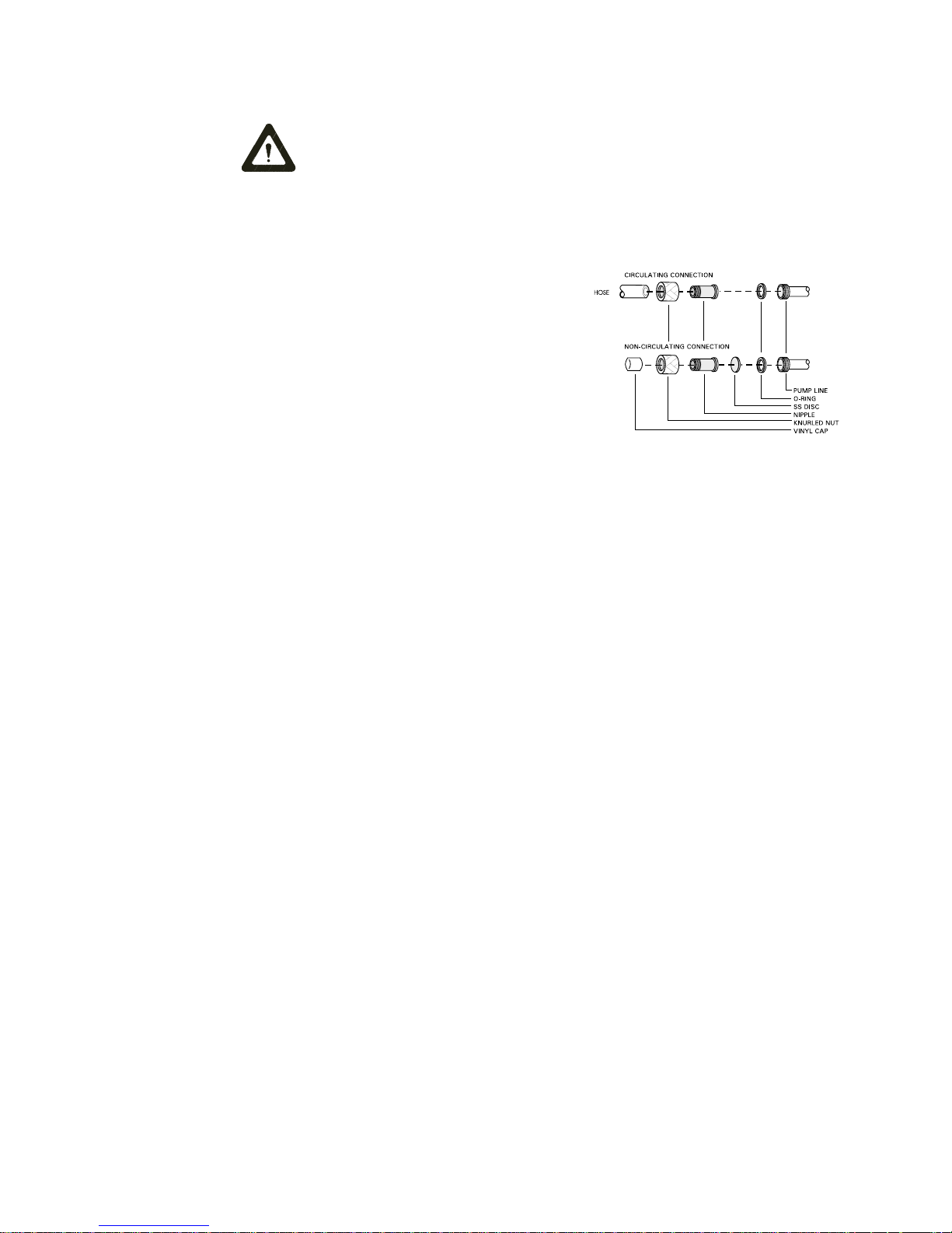
Hose ConnectionsHose Connections
Hose Connections
Hose ConnectionsHose Connections
The pump connections are located at the rear of the pump box and are
labelled PUMP INLET and PUMP
OUTLET. These connections are bent
upward so the recirculating fluid will
drain back into the reservoir when the
hoses are disconnected. Both connections are capped with stainless steel
serrated plugs.
The pump lines have ¼" male pipe
threads for mating with standard
plumbing fittings. For your convenience two stainless steel adapters, ¼" female pipe thread to 3/8" O.D.
serrated fitting, are provided. (To assure proper fit, they should be installed
using Teflon® tape around the threads.)
Flexible tubing, if used, should be of heavy wall or reinforced construction.
Make sure all tubing connections are securely clamped. Avoid running
tubing near radiators, hot water pipes, etc. If substantial lengths of tubing
are necessary, insulation may be required to prevent loss of cooling capacity.
Tubing and insulation are available from Thermo NESLAB. Contact our Sales
Department for more information (see Preface, After-sale Support).
It is important to keep the distance between the unit and the external system
as short as possible, and to use the largest diameter tubing practical. Tubing
should be straight and without bends. If diameter reductions must be made,
make them at the inlet and outlet of the external system, not at the unit.
If substantial lengths of cooling lines are required, they should be pre-filled
with bath fluid before connecting them to the unit. This will ensure that an
adequate amount of fluid will be in the bath once it is in operation.
PumpingPumping
Pumping
PumpingPumping
The pump is designed to deliver a flow of 15 liters/minute (4 gallons
minute) at 0 feet head. To prevent external circulation, the PUMP INLET and
PUMP OUTLET lines on the rear of the unit are capped. The caps must be
removed when external circulation is required.
To properly secure external hose connections to the unit, wrap Teflon® tape
around the pipe line threads before installation. Once the hose connections
are made, the hoses must be properly plumbed to an external system.
It is
important the bath is not in operation until all plumbing is complete.
NOTE: NOTE:
NOTE: To increase agitation in the bath when not circulating externally,
NOTE: NOTE:
connect a short loop of hose between the inlet and outlet lines.
If the bath is not used for external circulation, make sure the stainless steel
caps are in place prior to operating the bath.
- 6 -
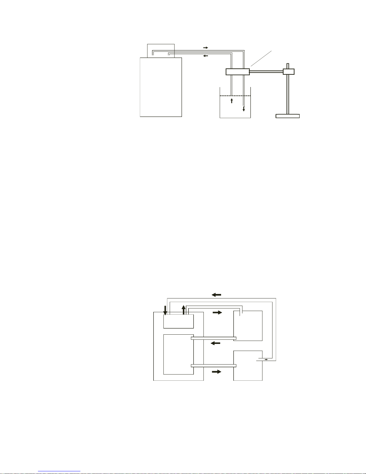
Circulating to an open containerCirculating to an open container
Circulating to an open container
Circulating to an open containerCirculating to an open container
Levelling Device
Outlet
Bath (Rear View) Open Container
Inlet
A stainless steel leveling device is available to aid circulation to an open
vessel. Contact our Sales Department for more information (see Preface,
After-sale Support).
Support the leveling device over the open container with a ringstand. Stagger
the tubes in the leveling device so one tube is submerged in the vessel fluid,
and the other tube is level with the fluid surface. Connect the deeper tube to
the PUMP OUTLET and the shorter tube to the PUMP INLET.
Adjust the flow rate using the accessory flow control valve connected to the
PUMP OUTLET, or by partially restricting the outlet tubing. When properly
adjusted, the pump inlet will draw an occasional air bubble to prevent over
flow, and the pump outlet will force fluid through the submerged tube to
prevent aeration of the vessel.
To avoid siphoning the bath work area when the unit is shut off, lift the
leveling device out of the vessel and above the level of the unit.
Circulating through two closed loopsCirculating through two closed loops
Circulating through two closed loops
Circulating through two closed loopsCirculating through two closed loops
Pump Box
Bath
Work Area
Bath (Top View)
System #1
System #2
The pump can be used to circulate through two closed loop systems.
Connect the shortest practical length of flexible tubing from the PUMP
OUTLET to the inlet of external system #1. Connect the outlet of system #1
directly into the bath work area. Connect tubing from the bath work area to
the inlet of system #2. Connect the outlet of system #2 to the PUMP INLET.
- 7 -
FluidsFluids
Fluids
FluidsFluids
DrainDrain
Drain
DrainDrain
Ensure the temperature of the bath fluid is safe before draining the unit.Ensure the temperature of the bath fluid is safe before draining the unit.
Ensure the temperature of the bath fluid is safe before draining the unit.
Ensure the temperature of the bath fluid is safe before draining the unit.Ensure the temperature of the bath fluid is safe before draining the unit.
The unit is equipped with a drain located at the back of the unit at the base of
the bath. The drain has ¼ inch male pipe threads and is capped with a
stainless steel plug. To drain the reservoir simply remove the cap.
To assure proper fit when replacing the cap, be sure to line the threads with
Teflon tape.
Never use flammable or corrosive fluids with this unit.Never use flammable or corrosive fluids with this unit.
Never use flammable or corrosive fluids with this unit.
Never use flammable or corrosive fluids with this unit.Never use flammable or corrosive fluids with this unit.
The selected fluid must have a viscosity of 50 centistokes or less at the
lowest operating temperature.
Filtered tap water is the recommended fluid for operation from +8°C to
+80°C.
FillingFilling
Filling
FillingFilling
RequirementsRequirements
Requirements
RequirementsRequirements
For operation from +8°C to -30°C, a 50/50 mixture, by volume, of filtered tap
water and laboratory grade ethylene glycol is suggested.
Above +80°C and below -30°C, the user is responsible for fluids used.
Never use pure ethylene glycol as a bath fluid. Never use pure ethylene glycol as a bath fluid.
Never use pure ethylene glycol as a bath fluid.
Never use pure ethylene glycol as a bath fluid. Never use pure ethylene glycol as a bath fluid.
mixture of Ethylene Glycol and filtered tap water is allowed.mixture of Ethylene Glycol and filtered tap water is allowed.
mixture of Ethylene Glycol and filtered tap water is allowed.
mixture of Ethylene Glycol and filtered tap water is allowed.mixture of Ethylene Glycol and filtered tap water is allowed.
The bath work area has a high and low level marker to guide filling. The
markers are 1 inch horizontal slits located in the center of the stainless steel
baffle separating the work area and the pump assembly. The correct fluid
level falls between these two markers. The heating and cooling coils will be
exposed and may become damaged if the correct fluid level is not provided.
When pumping to an external system, keep extra fluid on hand to maintain
the proper level in both the circulating lines and the external system.
Never run the unit when the work area is empty. Avoid overfilling.Never run the unit when the work area is empty. Avoid overfilling.
Never run the unit when the work area is empty. Avoid overfilling.
Never run the unit when the work area is empty. Avoid overfilling.Never run the unit when the work area is empty. Avoid overfilling.
Overfilling the bath may damage the insulation, and affects stability asOverfilling the bath may damage the insulation, and affects stability as
Overfilling the bath may damage the insulation, and affects stability as
Overfilling the bath may damage the insulation, and affects stability asOverfilling the bath may damage the insulation, and affects stability as
well as low-end performancewell as low-end performance
well as low-end performance.
well as low-end performancewell as low-end performance
A minimum 80/20A minimum 80/20
A minimum 80/20
A minimum 80/20A minimum 80/20
- 8 -
Section IV Micr Section IV Micr
Section IV Micr
Section IV Micr Section IV Micr
MicroprocessorMicroprocessor
Microprocessor
MicroprocessorMicroprocessor
ControllerController
Controller
ControllerController
opropr
DescriptionDescription
Description
DescriptionDescription
ocessor Controcessor Contr
opr
ocessor Contr
opropr
ocessor Controcessor Contr
olleroller
oller
olleroller
ss
s
ss
The microprocessor controller is designed as a separate component from the
unit. The controller can be mounted directly on the pump box, or remotely
from the bath. The controller provides proportional with integral and derivative (PID) control.
The controller has two sections. The upper section contains the LED indicators and the Main display which provide feedback to you about the controller
and bath. The ten individual LED indicators provide output on selected
parameters while the Main display will provide information on various unit
conditions. The lower section contains the keypad you use to input data to
the controller.
l SENSOR l HT l PROG l HEAT
l RS232 l LT l HOLD l COOL
EXTERNAL ALARM PROGRAM
l MUTE l FAULT
88.88
SENSORSENSOR
SENSOR
SENSORSENSOR
RS232RS232
RS232
RS232RS232
ON/OFFON/OFF
ON/OFF
ON/OFFON/OFF
Controller MountingController Mounting
Controller Mounting
Controller MountingController Mounting
HT/LTHT/LT
HT/LT
HT/LTHT/LT
mmm m
MUTEMUTE
MUTE
MUTEMUTE
mmm m
mmm
Microprocessor Temperature Controller (Front View)
HOLDHOLD
HOLD
HOLDHOLD
PERIODPERIOD
PERIOD
PERIODPERIOD
LOOPLOOP
LOOP
LOOPLOOP
SETPTSETPT
SETPT
SETPTSETPT
ENTERENTER
ENTER
ENTERENTER
CLEARCLEAR
CLEAR
CLEARCLEAR
mm
PROG/STOREPROG/STORE
PROG/STORE
PROG/STOREPROG/STORE
RUN/STOPRUN/STOP
RUN/STOP
RUN/STOPRUN/STOP
11
1
11
44
4
44
77
7
77
±±
±
±±
22
2
22
55
5
55
88
8
88
00
0
00
33
3
33
66
6
66
99
9
99
..
.
..
The controller can be removed from the bath and placed in a remote location. Extension cables are available from Thermo NESLAB. Contact our
Sales Department for more information.
Controller ConnectionController Connection
Controller Connection
Controller ConnectionController Connection
Microprocessor controllers are supplied with a cable needed to connect the
controller to the pump box. Connect the cable to the 25-pin male connector
on the control box and the female connector on the pump box. Once the
connection is made, the unit is ready for operation.
NOTE:NOTE:
NOTE: The MAIN POWER should be OFF before connecting/disconnecting
NOTE:NOTE:
cables from the control box.
- 9 -

LED IndicatorsLED Indicators
LED Indicators
LED IndicatorsLED Indicators
The following table explains the controller LED indicators. The LEDs can be
on, off or flashing.
LED STATUS INDICATION
SENSOR OF F All controller functions are operating from the
unit's internal probe.
ON All controller functions are operating from
remote sensor input.
FLASHING The Main display indicates the remote sensor
temperature. The controller, however, still uses
the internal probe to control the bath
RS232 OFF Communication port disabled.
ON Communication port enabled.
FLASHING Awaiting next key press
LT OFF No alarm.
ON Main display indicates low limit setpoint.
FLASHING Low limit alarm condition.
HT OFF No alarm.
ON Main display indicates high limit setpoint.
FLASHING High limit alarm condition.
temperature.
HOLD OFF Programming hold feature disabled.
ON Programming hold feature enabled.
PROG OFF No program running.
1
ON The program is suspended
.
FLASHING The program is running.
2
COOL OFF Refrigeration is off
.
ON Refrigeration is on.
HEAT OFF The heater is off.
ON The heater is on.
FLASHING The heater duty cycle.
MUTE OFF The alarm is enabled.
ON The alarm horn is disabled.
FLASHING The alarm horn has been disabled for any
current condition. The alarm horn will automatically reset when the condition is cleared.
FAULT OFF No fault condition.
ON The high temperature/low level safety
has activated.
1.The bath fluid will maintain the setpoint achieved at the time the program is suspended,
except when the bath is in a rapid cool segment. No operator inputs are available to the
controller while in a suspended condition.
2.Below 40°C the refrigeration is on unless the setpoint is more than 2°C above the bath
temperature. This allows rapid heat up. Above 40°C refrigeration is off.
- 10 -
 Loading...