

Thermona THERM ELN 8, THERM ELN 15 Installation, Operation And Maintenance Manual

09/2015
Installation,
operation and
maintenance
manual
for electric
boilers
(User´s Manual)
Version: September 2015
THERM ELN 8
THERM ELN 15

2
1. CONTENTS
1. CONTENTS ................................................................................................................................................ 2
2. USE .............................................................................................................................................................. 3
3. GENERAL DESCRIPTION ..................................................................................................................... 3
4. TECHNICAL DATA ................................................................................................................................. 6
5. BASIC INSTRUCTIONS FOR THE BOILER ASSEMBLY ................................................................ 6
6. BOILER OPERATION ........................................................................................................................... 10
7. SPECIAL BOILER FEATURES ............................................................................................................ 13
8. COMMISSIONING ................................................................................................................................. 13
9. GRAPH OF CONNECTING OVER-PRESSURE VALUES OF HEATING WATER THAT CAN
BE APPLIED ...................................................................................................................................................... 15
10. EL. CONNECTION OF THERM ELN BOILERS ............................................................................... 16
11. WARRANTY AND RELIABILITY FOR DEFECTS .......................................................................... 18
12. INTERCONNECTION WITH THE SOLAR SYSTEM ...................................................................... 18
13. DHW HEATING ...................................................................................................................................... 19
14. THERM ELN 8 BOILER SET ................................................................................................................ 20
15. THERM ELN 15 BOILER SET .............................................................................................................. 20
16. DIMENSIONS AND CONNECTIONS .................................................................................................. 21
17. RECORD OF WARRANTY REPAIRS AND ANNUAL INSPECTIONS ......................................... 22

3
2. USE
The THERM ELN boiler is a suspension hot-water electric boiler designed for heating hot water systems
with forced water circulation. The electric boiler can be used as a universal heat source for heating flats, family
and holiday homes as well as an alternative source when another main heating source is used, such as heat
pumps, accumulation systems, etc.
In addition to heating, the boiler can also be used to heat domestic hot water (DHW) in an external indirect
storage tank (so called DHW module needs to be added).
3. GENERAL DESCRIPTION
THERM ELN boilers come with two output levels: 8 and 15 kW. T he cor e of t he el ectri c boil er co nsis ts of
a steel vessel with integrated heating rods, heating temperature sensor and safety thermostat. The vessel is made
of coated sheet steel with thermal insulation. In the bottom part of the boiler vessel there are return water and
heating water outlets. The collar in the upper part of the vessel is adjusted for the temperature sensor pocket and
emergency thermostat sensor pocket. In the upper part of the vessel, there are threaded coupling sleeves. The
7.5 kW heating rods (1-2 pcs - in each heating rod, there are three separate 2.5 kW heating bodies) are bolted
to the coupling sleeves. The bottom part of the boiler features a special hydroblock which is fitted with a
circulation pump, by-pass, pressure sensor and heating system filling and discharge valves. At the highest point
in the boiler´s water circuit, there´s an automatic air vent valve.
The boiler is controlled and regulated by the automatic microprocessor control system which is situated in
the upper part of the boiler under the control panel, along with other electric components (contactor, main
wiring terminals).
The boiler switch, circuit breaker and power lines for the heating rods, is not situated on the boiler, but
is part of the el. switchboard for the given flat or house. During installation of the electric boiler, there needs
to be sufficiently dimensioned main contactor or switch (properly marked!) connected in its immediate
vicinity, which is used to disconnect the electric boiler from the mains.
♦ Description of the boiler operation:
The operating phase of the boiler is initiated when the temperature of the heating system drops under the
temperature set on the boiler control panel or under the temperature set on the room thermostat. The control
circuit of the heating rods is activated and the heating water in the boiler body is heated up gradually. When the
required room temperature is reached (when the room thermostat is used), the microprocessor control unit starts
disconnecting the heating bodies one by one and the heating water will no longer be heated. At this moment, the
adjustable pump rundown is activated.
In order to ensure maximum safety, the THERM ELN boiler comes with an emergency thermostat as
standard. The emergency thermostat is connected within the control circuit of the integrated electric contactor.
The emergency thermostat is disconnected, and thus the boiler is put out of operation (disconnection of the
control circuit of the relay and heating rods), once the temperature reaches 105°C. When the emergency
thermostat has been disconnected, only an authorized service technician may put the boiler back into operation.
Another safety feature of the boiler includes the pressure sensor which disconnects the control circuit if the
water pressure in the heating system decreases (a lack of water in the heating system). When water in the
heating system has been re-filled, the boiler is put back into operation automatically. Before the boiler is
switched on and while it is in operation, air needs to be bled properly out of the heating system. Air is bled out
of the heating system partly via the automatic air vent valves situated at the highest point of the boiler body and
on the pump.

4
♦ Some main properties and advantages of THERM- ELN electric boilers:
• Precise microprocessor con trol
• Easy-to-read two -digit LED display (shows the selected temperature, pressure, output, failures and
other messages)
• Very quiet operation (switch relay of the heating bodies)
• Modern design
• Compact dimensions
• Ergonomic, interactive digital control
• Smooth regulation in 2.5 (5.0) kW increments
• Energy-saving circulation pump with run-down adjustable during servicing
• Pump protection against blocking
• Anti-freeze protection
• Possibility of DHW heating (the DHW module needs to be added)
• Possibility of controlling the output temperature by 0 – 10 V signal
• Integrated safety switch contactor of all output phases
• Even load of the heating rods and heating bodies
• Switching system of the boiler using the HDO signal (demand site management)
• Integrated circulation pump, expansion vessel, by-pass, safety valve
• Integrated refill and discharge of the heating water
• Automatic bleeding
• Digital heating water pressure sensor
• Auto-diagnostics, clear service error messages
• Possibility to set selected boiler parameters (service menu)
♦ Brief description of the main advantages of the THERM ELN electric boiler:
Easy and intuitive control
The control system is designed in such a way so as to be simple, comprehensible and clear. The ease of control
is supported by the clearly arranged LED display with clear signals provided by LED indicators.
Pump protection against blocking
If the pump is cranked up regularly once every 24 hours, it will prevent the pump from being blocked during a
longer shut-down of the boiler. Furthermore, when the panel (boiler) power supply is switched on, the
circulation pump will turn on after the first 10 seconds even if heating is not requested. In such a case, it will
remain in operation for 30 seconds.
Possibility of DHW heating
The THERM ELN boiler can be connected with an external indirect storage tank for DHW heating. The tank is
heated with the heating water t hanks to the three-way valve adjustment. In order to ensure DHW heating, the
boiler control panel needs to be extended with the so called DHW module.
External controls
The boiler can be controlled by the room thermostat. Boiler control by the room thermostat leads to further
energy savings.

5
Safety switch contactor
A safety 3-phase contactor is integrated in the electric power branches on the boiler inlet.
In emergency cases and in other abnormal conditions, the contactor can cut off current from the heating rods,
thus preventing any dangerous situations.
Overheating protection
If the heating water temperature exceeds 95°C, overheating error E.3 is reported. The error will be cl ea r e d whe n
the temperature drops below 91°C.
Uniform load on the heating rods
The principle of uniform load on the heating rods helps to increase their service life. The rod which was
connected first will be the first one to be disconnected in the regulation cycle, which leads to increased overall
reliability and a longer service life of the appliance. The processor evaluates the time of operation of the
individual heating rods and switches them on in such a way so that the boiler (boiler body) is under uniform
thermal load, if possible, and
the rods are under uniform operating load.
Switching system of the boiler by HDO
The THERM ELN boiler signals and responds to commands from the HDO receiver from the external
switchboard. The receiver output shall be a signal connected with the neutral wire which is connected to the
HDO/N terminal. This remote control method makes it possible to operate the boiler when the tariff rate is low,
thus considerably reducing the electricity costs.
!!! In case of other methods of HDO receiver installation, with a phase (HDO/L1 -L3) as the output, transfer to
the N level (neutral wire) needs to be ensured in the external switchboard by installing an auxiliary relay etc.!!!
Analogue signal control
The heating water output temperature can be controlled within the given range by analogue signal – control
voltage from 0 to 10V.
Auto-diagnostics, clear signals and service messages
The THERM ELN electric boiler features a very useful auto-diagnostics system - especially for service
purposes. This feature helps to eliminate any boiler defects quickly and effectively.
6
4. Technical data
♦ Production control
All parts of the boiler are checked and set by the producer before assembly. Each boiler is tested for leak
tightness of the water circuit, and the control and safety features are adjusted and tested. The boiler is
manufactured in accordance with: CSN EN 60 335-1, CSN EN 60 335-1 ed.2, CSN EN 60 335-1 ed.3 CSN EN
60 335-2-30 ed. 2, 60335-2-30 ed.3, CSN 06 1008, CSN 07 7401, CSN 07 0240, CSN 06 0310, CSN 06 0830,
CSN EN 60 730-1, CSN 06 1010, NV no. 163/2002 Coll., NV 17/2003 Coll., NV 616/2006 Coll.
5. Basic instructions for the boiler assembly
The electric boilers are designed for operation without necessary electrical engineering qualifications. The
operator may only handle the controls specified in this manual. Under no circumstances shall the operators
interfere with electrical wiring.
The electric boilers are intended for permanent connection to fixed wiring with mains voltage. A switch-off
device shall be integrated in the fixed wiring of the electric boiler – main switch and adequate circuit breaker.
Electric boilers may only be assembled by a qualified company or authorized technician with the necessary
electrical engineering qualifications, in compliance with any advice and notices contained in this manual.
Assembly shall be carried out in compliance with applicable standards and regulations! Connection of the
electric heating is subject to approval by the local electricity distribution plant. The applicant needs to request a
preliminary approval with the potential connection of higher input power and request the relevant rate. If new
central heating is constructed or an old one reconstructed, we recommend that the project be drawn up by a
professional. A prerequisite for the manufacturer´s warranty is professional commissioning by an authorized
service company! Connection to the mains and electrical wiring may only be carried out by an expert having the
qualifications required by Czech Regulation no. 50/1978 Coll.
The installation site for the electric boiler shall provide necessary access for operation and service purposes.
Minimum distances between the boiler and a fixed barrier are shown in chapter “Suspending the boiler”. After
THERM ELN 8 THERM ELN 15
Nominal heat output
kW
7.5
15
Minimum regulation level of the output
W
2500
5000
Number of output regulation levels
-
3
3
Rated current
A
11(33)
22
Degree of protection
IP
40
Electric voltage / frequency
V/Hz
3 x 400 + N + PE/50
Maximum rated current
A
3x 12 (1x36)
3 x 24
Main circuit breaker for electric installation
A
16 (40)
25
Rated current of the control circuit breaker
A
1.25
Electric service life of relay
-
1.105 cycles (16 A, 250V/50 Hz)
Mechanical service life of relay
-
10.106 cycles
Heating water inpu t - output
-
G 3/4" outer
Min. working overpressure of the heating system
bar
0.5
Max. working overpressure of the heating system
bar
3.0
Maximum temperature of heating water
°C
80
Water volume of the boiler
1
6.8
9.6
Efficiency at the rated power
%
99.5
Capacity of expansion tank
1
7
Dimensions (height/width/ de pth )
mm
800/400/235
Weight of the boiler without water (gross)
kg
31 (34)
33 (35)
7
assembly, request a demonstration of the boiler operation and have operators trained by a professional from the
assembly company. After commissioning, the authorized service technician shall confirm the warranty card for
the electric boiler.
For the electric boiler installation, there needs to be pressured water available on site in order to fill the
system.
♦ Location of the boiler
The electric boiler may be installed in the basic AA5/AB5 environment according to CSN 2000-3 and CSN
33-2000-5:51 ed.3 (temperature range from +5 to 40°C,
humidity depending on the temperature up to max. 85%,
without harmful chemical effects). Suitable for
installation in both residential and non-residential
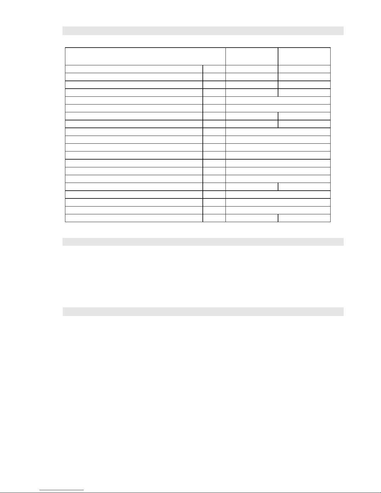
premises. The boiler shall not be installed in areas with a
bath, in bathrooms, shower rooms in zones 0, 1 and 2
according to CSN 33 2000-7-701 ed.2:2007 and in wash
rooms according to CSN 33 2130 ed.2:2009. In addition
to that, it shall not be installed in zone 3 either if there is
a chance that a jet of water intended for cleaning might
be present. When the boiler is installed in permissible
zones, appropriate protection from electric shock needs
to be ensured according to the aforementioned standard.
There shall be necessary access for operation and service purposes on the installation site.
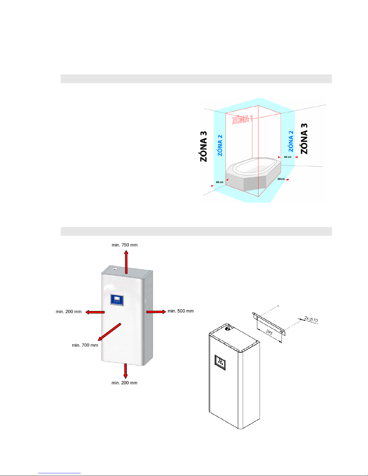
♦ Suspending the boiler
The electric boiler shall be mounted to a wall using
the suspension bar, wall plugs and screws included
in the delivery. For ideal suspension, the room
needs to have a flat wall with a sufficient loadbearing capacity. Direct suspension e.g. from
plasterboard structures is not recommended. In case
of installation on a wall with a lower load-bearing
capacity, it is recommended that a construction technician
be consulted. Under the bottom edge of the boiler and
above the upper edge of the casing, a service space of at
least 200mm and 750mm, respectively, needs to be
maintained for the purposes of inspection or replacement of
the heating bodies.
 Loading...