

Thermona THERM EL 8, THERM EL 15, THERM EL 30, THERM EL 23, THERM EL 38 Operating Instructions Manual
...
Operation and
Maintenance
Manual for
Electric Boilers
(user manual)
version: February, 2008
THERM EL 8
THERM EL 15
THERM EL 23
THERM EL 30
THERM EL 38
THERM EL 45

2
1. CONTENTS
1. CONTENTS ................................................................................................................................................ 2
2. GENERAL USE ......................................................................................................................................... 3
3. GENERAL CHARACTERISTICS OF THERM – EL ELECTRIC BOILERS .................................. 3
4. TECHNICAL DATA ................................................................................................................................. 7
5. BASIC INSTRUCTIONS FOR BOILER INSTALLATION ................................................................. 8
6. BOILER OPERATION ........................................................................................................................... 13
7. BOILER CONTROL AND DISPLAY OF BASIC OPERATIONAL INFORMATION .................. 16
8. USER MENU ............................................................................................................................................ 19
9. PUTTING THE BOILER INTO OPERATION.................................................................................... 21
10.
DIAGRAM FOR SERVICEABLE CONNECTING CHARGE PRESSURES OF HEATING WATER
....... 23
11. THERM EL BOILERS CONNECTION TO THE POWER SUPPLY............................................... 24
12. WARRANTY AND RESPONSIBILITY FOR DEFECTS................................................................... 31
13. DOMESTIC HOT WATER STORAGE TANK HEATING MODE .................................................. 31
14. THERM EL 8, 15, 23 BOILER ASSEMBLY (KW) ............................................................................. 33
15. THERM EL 30, 38, 45 BOILER ASSEMBLY (KW) ........................................................................... 34
16. WALL-MOUNTING OF THE BOILER ............................................................................................... 35
17. BOILER DIMENSIONS AND CONNECTION.................................................................................... 35
18. RECORD OF REPAIRS AND ANNUAL INSPECTIONS .................................................................. 36

3
2. General use
The construction of THERM-EL electric boilers is designed for hot-water heating systems with induced
water circulation. They can be installed in central or individual-storey heating with induced circulation sealed or
open systems and they are characterized by an environmentally friendly operation without requirements for
venting of the combustion product. Service-free operation enables the installation of an external regulator, other
external regulating or controlling components (not included in the boiler delivery package!), simple equitherm
regulator or room thermostat integrated directly in the automatic controlling system which maintains the pre-set
room temperature. The electric boiler can be used as a universal source of heat for heating flats, small family
houses, resort houses and also as an alternative source to another main heat source of heating and hot water
preparation (also for transitional periods) – for heat pumps, accumulation systems or in previously installed
central or single-storey heating systems etc. To attain higher output levels, boilers can be connected into a
cascade format.
3. General characteristics of THERM – EL electric boilers
Therm-EL electric boilers are wall-mounted appliances designed for water heating in a heating system and
potentially for domestic hot water heating (hereinafter referred to as “DHW”) in an indirect heating storage
tank.
THERM-EL electric boilers are manufactured in three performance versions in the lower output category:
8, 15 and 23 kW. The higher output series offers the following three types: 30, 38 and 45 kW. Structural
design as well as controlling system of these boilers are almost identical to the lower output series.
The electric boiler is formed by a steel vessel with inbuilt heating bars, heating temperature probe and safety
thermostat (these components are all located under one cover in the upper part of the vessel). The vessel is made
from a varnished steel sheet and it is fitted with thermal insulation. Heating water inlet, on which a circular
pump is mounted, is welded at the bottom part of the boiler. A lug located in the upper part of the vessel is
adjusted to the cup for the boiler temperature sensor and emergency thermostat. Heating water outlet and
threaded sleeve pieces are also located in the upper part of the vessel. Heating bars (up to 6) are screwed in the
sleeve pieces. Total output of each heating bar is 7.5 kW (there are three separate heating bodies with the output
of 2.5 kW in each heat bar). An automatic vent valve is placed at the highest point of the water heating circuit.
The boiler control box enables connection of an external room thermostat, addition of interface for the boiler
cascade connection type, programmable (time) switch and MRC (mass remote control) tariff switch.
Switching and electric line protection of the boiler and output inlets for the heating bars are not
located in the boiler but they always form part of the electric distributor of the flat or house. Terminals of the
main wiring are concentrated in the right part of the boiler. A sufficiently rated output line contactor or switch
(correctly marked!) which are used for disconnecting the electric boiler from the power network must be
connected right next to the boiler during its installation.
♦ Boiler operation characteristics:
Operational stage of the boiler is launched when heating system temperature drops below the temperature
set on the boiler control panel or on the room thermostat. Control circuit of the heating bars becomes activated
and heating water inside the boiler body becomes heated gradually. After the required temperature has been
reached in the room (if a room thermostat is applied), the control microprocessor unit starts switching off the
heating bodies one by one and the heating of the water stops. At this moment the function of an adjustable
limited pump deceleration (in terms of time or temperature) becomes activated.
As standard, Therm-EL boilers are also fitted with emergency thermostat which delivers maximum safety.
It is connected to the control circuit of the integrated output contactor. The disconnection of the emergency

4
thermostat (disjunction of the controlling circuit relay and heating bars) and thus the boiler shut-down occur
when the temperature reaches 105°C. Shall the emergency thermostat become disconnected, the boiler can be
only put back into operation by an authorized service engineer. Another protection of the boiler is assured by a
pressure switch which disengages the control circuit when the heating system water pressure decreases (when
there is not enough water in the heating system). When the system becomes replenished with water, the boiler
automatically relaunches operation. Proper deaeration of the heating system must be assured prior to launching
and also during boiler operation. The heating system bleeding is partially ensured by the automatic vent valve
which is placed at the outlet of heating water from the boiler body.
♦ Selected important characteristics and merits of THERM- EL electric boilers:
• top microprocessor control
• very quiet operation (switch power relay of the heating bodies)
• state-of-the-art design
• ergonomic, interactive control
• smooth regulation – 2.5 kW regulation step (5 kW with the higher performance series)
• service-adjustable pump deceleration
• protection of the pump against particulate build-up
• PID regulation
• anti-freeze protection
• DHW heating option (terminals for an external three-way valve, NTC temperature sensor or a storage tank thermostat)
• optional connection of an external NTC sensor (integrated equitherm regulation)
• connection of an NTC temperature room sensor (automatic controlling system as a room regulator)
• integrated safety switch contactor for all output phases
• possibility of an intelligent cascade boiler connection format (up to 32 boilers – with smooth output modulation)
• optional external control by means of GSM (external modem necessary)
• optional connection of an external regulator with OpenTherm communication
• balanced loading of the heating bars and bodies
• power relays do not form part of the processor board printed circuits (easy servicing and replacement). Special relays with
integrated fastons were used, i.e. high currents do not flow through printed circuits.
• boiler start system functioning on the basis of a mass remote control (MRC)
• external control of energy input (relief relay)
• soft start
• integrated Grundfos UPS 15/60 pump
• integrated 7 l expansion vessel (with the lower performance series)
• integrated safety valve
• automatic bleeding
• digital heating water pressure sensor (fitted with all types)
• auto-diagnostics, unequivocal service notification of defects
• optional boiler parameter adjustment (rich service menu)
• three-digit display (displays selected temperatures, pressure, output, error messages etc.)
• further 7 LEDs for unequivocal signalling of the operational conditions
• option of a default setting (immediate change of operation into the factory settings mode)

5
♦ Brief characteristics of the main merits of THERM-EL electric boilers:
Simple and intuitive operation
The control is designed in a simple, understandable and unambiguous way. Simple operation is also enabled by way of a
three-digit LED 7-seg display complemented by an unambiguous signalling system of a series of LEDs.
Pump protection against clogging
Regular spinning of the pump (once every 24 hours) prevents potential clogging of the pump during an extended boiler
down time.
Optional DHW heating
It is possible to additionally connect an external indirect DHW heating storage tank to the THERM-EL boiler. Heating of
the storage tank water is ensured by means of changing the position of the three-way valve. The boiler electronics can
communicate with the temperature sensor (continuous DHW temperature regulation) as well as with the traditional storage
tank thermostat (can be set in the service menu).
External regulatory elements
Boiler control by way of room thermostat or equitherm sensor is commonplace. Connection of the boiler to the room
thermostat or equitherm probe leads to further savings for electricity. The THERM-EL boiler is moreover able to cooperate
with regulators communicating via the OpenTherm communication protocol. Additional communication interface is not
necessary.
If the NTC temperature sensor is connected only in a room of reference according to which the whole heated space is
regulated, automatic control system can be used as a simple room regulator! (This can be set in the user menu.)
Safety switch contactor
Safety three-phase contactor is inserted in the power branch circuit at the boiler inlet which can cut the power from the
heating bars in case of emergencies and detected incorrect conditions (for further details see auto-diagnostics of the
automatic control system) and prevent a potentially dangerous situation from occurring.
Boiler cascade connection format option
The boiler electronics enable connection of up to 32 boilers into a single intelligent cascade which modulates the
performance ranging from minimum output of the first boiler to the total of maximum outputs of all boilers combined. The
interconnection of the master and slave boilers is possible only through a system of intelligent modules – i.e. the same
interface must be used for master as well as slave boilers.
GSM operated boiler
The boiler can be switched on and off by means of a mobile phone (it is however necessary that an external modem is
used; the modem is not an item of the boiler delivery package!). The boiler operation can be remotely launched by calling
on a GSM modem connected to the boiler, for example prior to returning from holiday, so that the house has a pleasant
temperature at the time of arrival.
Balanced service load of heating bars
Principle of a balanced service load on the heat bars extends their life-time. The heating bar which was connected first will
be also disconnected first within the framework of the regulation cycle which leads to an increase in overall reliability and
prolonged durability of the appliance. The processor assess the operational time of individual heating bars and actuates
them in a manner which ensures a thermally balanced loading of the boiler (the boiler body) and even service load of the
bars.
MRC system for launching the boiler operation
THERM-EL boilers signal and respond to commands from the MRC receiver of the external distributor. The output signal
of this receiver must be connected to the reset conductor which is attached to the MRC/R terminal. This method of remote

6
control enables the boiler to operate in a low tariff rate and thus significantly reduce energy costs. Maximum boiler output
can be limited in the service menu if the operation must proceed also outside the so-called “low tariff”.
!!! Shall other ways of installing the MRC receiver be applied the output of which is one of the phases (MRC/L1
-L3), it is necessary to assure transmission to the R level (reset conductor) by means of e.g. installing an
auxiliary relay in the external distributor.
Soft start
The soft start function rests in a gradual heat-up of the heating system which is therefore protected against abrupt upward
temperature gradient. When the boiler is switched on or a new regulation period is initiated and the resulting quick change
in temperature caused by induction of heat into the system could also bring about noise due to the dilatation of pipes, the
boiler is actuated in the so-called “soft start” and limits the output after it is launched.
Auto-diagnostics, unambiguous signalling and service messages
THERM-EL electric boilers are equipped with a very useful system of auto-diagnostics chiefly with respect to service.
This function facilitates speedy and efficient removal of a potential boiler defect. Apart from the commonly displayed user
values – heating water temperature (the TOP circuit), DHW temperature, outdoor or room temperature sensor, TOP circuit
pressure – the display can show other service information if the service menu is set up correspondingly: E.g. disconnection
or short circuit of all sensors, boiler output, MRC condition and other error messages.
Wide choice of parameter settings
Service and user menus of THERM-EL boilers provide a wide range of boiler settings according to specific conditions of
operation or based on customer requirements:
- The option of setting various outputs for the heating water and heating of DHW undoubtedly offers positive financial
effects.
- The possibility of setting different outputs with the MRC signal switched on or off provides the user with a pleasant heat
comfort.
External energy input control
If there are several concurrently operating electrical apparatuses and the household has increased requirements for power
take-off, the THERM-EL boiler user will certainly appreciate the external energy input control function. A relief relay can
be connected to the distributor with a pre-set value of the electric current. If the current reaches e.g. 30 A, the boiler
disconnects a specified number of heating bars and relieves the whole system.
SLEEP standby mode
Another function the advantage of which will be namely appreciated by those users who stay outside home for longer
periods of time is the SLEEP mode. This mode is used in situations when the house will not be inhabited for an extended
period and the user wants to have the heating system reliably safeguarded against solidification or freeze-up. Boiler in the
SLEEP mode consumes minimum amount of power but the protective boiler functions – spinning, unblocking and antifreeze protections – are also active. If the boiler is connected to an equitherm sensor, the drop in outside temperature
activates an anti-freeze protection which can protect not only the actual boiler but the entire heating system.
If during the boiler's operation (i.e. not only in the SLEEP mode) none of the control panel buttons becomes
activated (when heating and DHW heating are switched off by the respective button), the display automatically
switches over to the saving mode (only the LED is turned on).
7
4. Technical data
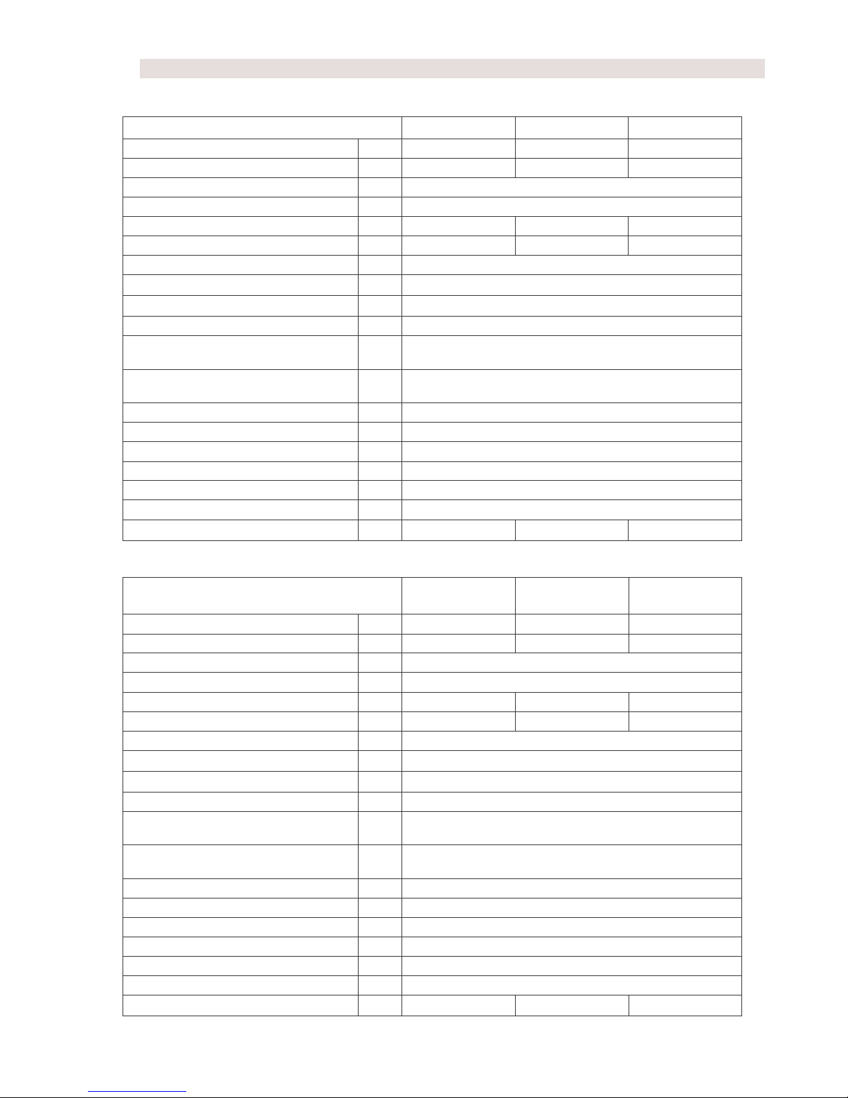
Lower performance series:
THERM EL 8 THERM EL 15 THERM EL 23
Nominal heat output kW 7.5 15 22.5
Rated current A 11 22 33
El. components degree of shielding IP 40
Power voltage / frequency
V/Hz
3 x 230 + N + PE/50
Max. rated current A 3 x 12 3 x 24 3 x 36
Wiring main circuit breaker A 16 A 32 A 40 A
Rated current of the control system fuse
A 1.25
Electric durability of the relay - 1.105 cycles (16 A. 250V/50 Hz)
Mechanical durability of the relay - 10.106 cycles
Heating water inlet/outlet - male G 3/4"
Min. service overpressure of the
heating assembly
bar 0.8
Max. service overpressure of the
heating assembly
bar 2.5
Max. heating water temperature °C 80
Boiler water capacity 1 14.5
Effectiveness for nominal output % 99
Expansion vessel capacity 1 7
Max. number of boilers in the cascade pcs 32
Dimensions (height/ width /depth) mm 805/475/235
Boiler weight without water kg 39.5 42.5 45.5
Higher performance series:
THERM EL 30 THERM EL 38 THERM EL 45
Nominal heat output kW 30 37.5 45
Rated current A 44 55 66
El. components degree of shielding IP 40
Power voltage / frequency
V/Hz
3 x 230 + N + PE/50
Max. rated current A 3 x 48 3 x 60 3 x 72
Wiring main circuit breaker A 50 A 63 A 80 A
Rated current of the control system fuse
A 1.25
Electric durability of the relay - 1.105 cycles (16 A. 250V/50 Hz)
Mechanical durability of the relay - 10.106 cycles
Heating water inlet/outlet - male G 1"
Min. service overpressure of the
heating assembly
bar 0.8
Max. service overpressure of the
heating assembly
bar 2.5
Max. heating water temperature °C 80
Boiler water capacity 1 28.0
Effectiveness for nominal output % 99
Expansion vessel capacity 1 to order (placed outside the boiler!)
Max. number of boilers in the cascade pcs 32
Dimensions (height/ width /depth) mm 805/475/235
Boiler weight without water kg 56.5 59.5 62.2

8
♦ Manufacturing control
All boiler parts are checked and correctly set by the manufacturer prior to final assembly. Each boiler is
tested on water circuit tightness and the function of the regulating and safety components is set and tested as
well.
The boiler was manufactured in line with:
Standards: CSN EN 60 335-1, CSN EN 60 335-2-30, CSN 06 1008, CSN 07 7401, CSN 06 0810, CSN 07
0240, CSN 06 0310, CSN EN 60 730, CSN 06 0830, CSN EN 60 730-1, CSN 06 1010; Government
Regulations: No. 163/2002 Coll., 17/2003 Coll. and 18/2003 Coll.
5. Basic instructions for boiler installation
Electric boilers are designed for permanent connection to a fixed mains supply voltage. A disconnecting
device – main circuit breaker and a corresponding electric line protection – must be installed in the permanent
electric boiler mains.
Installation of electric boilers can be carried out only by a qualified expert company or authorized worker
with the required qualification level in the field of electrical equipment maintenance. In the process of
installation, all pieces of advice as well as warnings included in this Manual must be observed. It must be
performed in compliance with the valid standards and provisions! The connection of an electric heating is
subject to authorization issued by the local power distribution plant. An applicant must ask for a provisional
approval with the connection of a higher energy input and for a relevant direct heating dwelling unit tariff. In
the case of construction of a new or repair of an old central heating system, we suggest that the design is
elaborated by an expert. Performance of an expert installation by an authorized service organization is always
the precondition for warranty provision by the manufacturer! Connection to the electric network and the wiring
can be carried out only by an expert worker qualified in line with the Czech Decree No. 50/1978 Coll.
Installation location must be chosen for the electric boiler which will enable necessary access for the
operator or for the purposes of a service inspection. Minimum distances between the boiler and a solid obstacle
are shown in the Figure in the Chapter “Wall-mounting of a boiler”. Ask an expert worker of the company
which performs the installation for a demonstration of the system function and training for operation. Once the
boiler has been put into operation, a letter of guarantee must be certified by the authorized expert service
worker.
In the location of the electric boiler installation pressure water for filling the heating system and water
discharge point must be available. It is further necessary that the room has a sufficiently even wall (electric
boiler is wall-mounted).
♦ Boiler location
Electric boilers can be installed in the basic
environment AA5/AB5 according to the standards CSN
2000-3 and CSN 33-2000-5:51 (range of temperatures
between +5 and 40°C, humidity depending on the
temperature of maximum 85 %, no harmful chemical
influences). It can be installed in residential as well as
non-residential spaces with the exception of rooms with a
bathtub or shower, in bathrooms and wash rooms in
general in zones 1 and 2 according to CSN 33 2000-7-
701. It cannot be however installed in zone 3 in locations
where a water jet designed for cleaning can form. If the

9
boiler is installed in the permitted zones, relevant electric current accident protection must be concurrently
performed in accordance with the same standard, too.
The installation location must be chosen which will allow sufficient access for the operator as well as service
inspector.
Degree of shielding of the boiler electric components is IP 40.
♦ Wall-mounting of the boiler
Electric boiler is mounted on the wall by means of a
fixing strip (1) supplied with the boiler according to the
Figure in the Chapter “Wall-mounting of the boiler”. If
the boiler is mounted on a wall with a lower carrying
capacity, it is recommended to consult the installation
with a civil engineering technician. Free space of at least
200 mm below and 750 mm above the lower and upper
edges of the jacketing shall be left for the purposes of
inspecting the boiler or replacing the heating bodies (see
Figure depicting the boiler wall-mounting and
installation).
♦ Connecting the boiler to the hot-water heating system
Electric boiler must be connected to the distribution network in a manner preventing its aeration.
Connection to the heating system must be tackled in a project design calculating hydraulic ratios of the
whole system because the installation involves a hot-water flow-through boiler fitted with an integrated pump.
It needs be noted that minimum flow through the boiler must be constantly assured for the designated boiler
output at maximum thermal gradient of the heating system amounting to 20°C. Any reduction of this flow (due
to integrated high hydraulic friction elements) results in insufficient circulation and drop in life-time of some
boiler parts. To utilize the maximum output of the heat exchangers, ensure correct functioning and high
durability, the minimum heating system overpressure must amount to 0.8 bar.
Proper rinsing of the heating system resulting in the removal of all impurities must be performed prior to
testing and launching the operation of the whole system in line with CSN 06 0310 within the framework of the
installation. A suitable filter must be unconditionally fitted in the recuperative water inlet from the heating
system into the boiler to prevent impurities from entering the boiler system.
The heating system must be installed in accordance with CSN 06 0830 -- Safety equipment for central
heating and domestic hot water heating and CSN 06 0310 – Central heating – designing and assembly.
Shall the boiler be connected to a sealed heating system, such system must have a pressure expansion vessel
of sufficient capacity (higher performance series boilers are not equipped with their own expansion vessel).
!!! We recommend:
fill the system with soft water in line with CSN 07 7401;
fit the boiler outlet with a bleeding device;
mount a filter or a sludge device into the pump suction section;
overflow valve should be installed in heating systems with thermostatic valves
10
mount a heating system charge and discharge cock and a sludge cock at the lowest point of the system
in the very proximity of the electric boiler
separate all electric boiler types on inlet and outlet by stop valves, too (see standards CSN 06 8030), not
to be forced to discharge the whole system in case of inspection or repair of the boiler or during filter
replacement
remove control levers from stop valves and secure them against manipulation.
♦ Boiler connection to electric network
Wiring can be installed only by an authorized person in the sense of the Decree No. 50/1978 Coll. on
professional qualification in electrical engineering. Certification of the boiler installation and putting into
operation must be noted in a proper manner on the letter of guarantee. Any interference with internal boiler
wiring (with the exception of wiring specified in this Manual, e.g. the external regulator connection instead of
jumper wire) are inadmissible!
The boiler control box must be connected according to the relevant CSN standard by means of a
separately protected line which enables its disconnection and which is located in the very proximity of the
electric boiler!
Current protective switch must be used if the electric boiler is installed in a bathroom.
The power wiring is connected by a 5-conductor system to the U, V, W, N and PE terminals. In the case of a
4-conductor system the N and PE terminals shall be connected together and the power wiring matched with the
U, V, W and PE terminals.
If MRC is connected to the boiler control box, the MRC receiver outlet is matched with the terminal marked
HDO/N.1
WARNING! When using the MRC receiver signal on the HDO/N terminal, it must be made sure that all
contactor coils of other appliances (e.g. of the boiler if it is connected to the common MRC signal) are
energized with the same phase!
When operation must be delivered also outside the so-called “low tariff”, the maximum boiler output
limit can be switched off in the service menu also without the MRC signal (P4.4)!
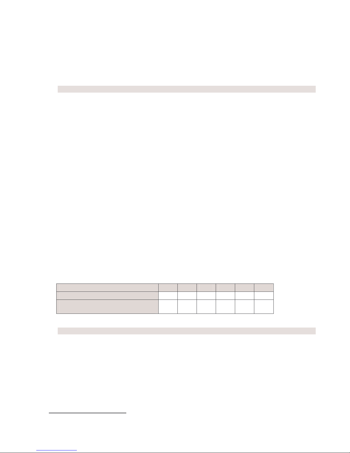
Recommended cable cross sections under the plaster:
Boiler output [kW] 8 15 23 30 38 45
Power take-off [A] 12 24 36 48 60 72
PVC insulated cable with copper
conductors 5 [sq.mm]
2,5 4 6 10 16 25
♦ Charging the heating system
For the duration of the heating system charging, the boiler must be unplugged from the electric network by
disconnecting it by the main circuit breaker. It is useful to maintain the level of filling pressure in a cold system
in the range between 1 and 1.5 bar. Filling must proceed slowly in order to let the air bubbles escape through
the respective valves. According to CSN 07 7401 the water used for the first filling as well as for refilling must
be clear, colourless, without any suspended substances, oil or chemically aggressive admixtures, with a
minimum carbonate hardness (max. 3.5 mval/l) and it cannot be acidic (pH cannot be below 7). Only approved
agents can be used for water hardness adjustments.
1
HDO is the Czech abbreviation for MRC: translator's note.

11
Non-observance of the aforementioned requirements results in cancellation of the undertaking for
the damaged components!
♦ Choice of the regulating and controlling components
The boiler is fitted with basic regulatory and safety elements as the following electric diagrams show.
Therm-EL boilers can regulate their outputs. They are equipped with their own PID regulation which does not
allow heating over the set temperature. Even if the TOP temperature is set to 80°C, electric boilers frequently
overheat up to the temperature of 96°C, while THERM-EL boiler heats up to the maximum temperature of
84°C.
It is always suitable and economical to let the electric boiler be controlled by a superior regulatory element
(room thermostat or an OpenTherm communication regulator). These regulators are not included in the boiler
delivery package!
Connection of a room thermostat and servicing of the boiler electric section may be carried out only
by authorized service organizations!
Regulation based on temperature in a referential room (room regulator) or an equitherm regulation of the
heating water, or potentially both, can be used as further extensions to the regulatory option. A whole series of
regulatory or switch thermostats can be used to control the room temperature: E.g. PT 10, PT 21, PT 30, BPT
30, PT 30 GSM, REV 23, CM 707, CM 907 or OpenTherm communication regulators such as Therm RC 03,
PT 55 (Elektrobock), QAA 73.110 (Siemens) or CR 04 Honeywell.
Regulators (room regulator, water temperature thermostat, trip relay of the current value monitor or an
OpenTherm regulator) can be connected to the boiler's input terminals (24V= circuits).
Current value monitor is a device used for disconnecting or reducing the output of the electric boiler when
other high power input electrical appliances (e.g. flow-through water heater, washing machine, dish-washer,
stove etc.) are connected to the network. Such a device is rules out the necessity of purchasing a high-capacity
main circuit-breaker which also means the payment of a high lump fee.
If a part of the electric boiler needs to be disconnected, the tripping device becomes connected to the
terminals for a trip relay (see the wiring scheme). The output size which becomes disconnected by individual
trip relays is set by changing the parameters in the control panel (from zero to maximum) in the service menu.
If the contact of the external tripping device should disconnect the whole boiler, it shall be either connected
serially in combination with the room thermostat (24V=) or to the terminals of the blocking element
(230V/50Hz).
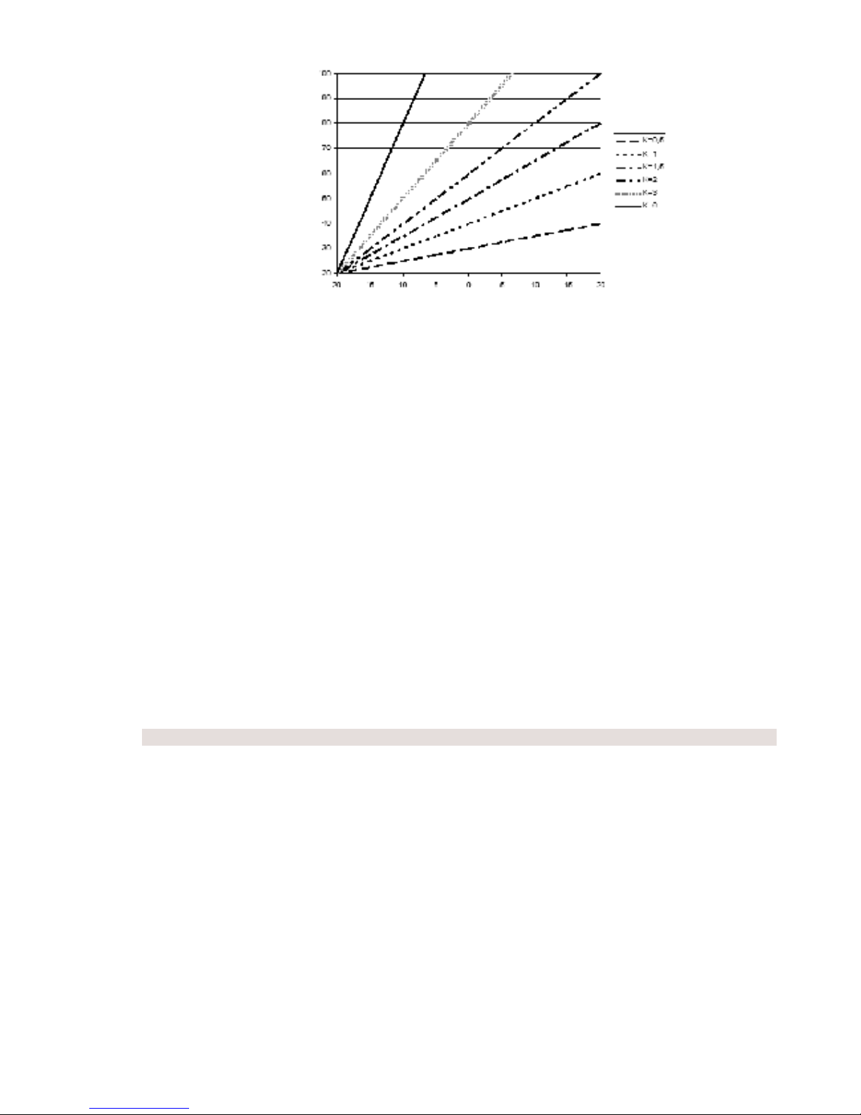
Equitherm regulation
Heating water temperature in the equitherm regulation system is controlled on the basis of outdoor temperature.
The regulation takes place according to equitherm curves which specify the dependence between outdoor
temperature and the temperature of heating water required to reach the desired room temperature. An equitherm
curve must be drawn on the basis of designed, calculated or measured heat losses of the building. This type of
regulation does not have any feedback which would take into account higher cooling on one side of the house
by wind or heating by sun and, as a result, it cannot safeguard accurate temperature regulation in all parts of the
house.
Boiler connection to room thermostat and Therm Q01 outdoor sensor enables utilizing the equitherm regulation
which leads to additional energetic cost-cutting. THERM-EL boiler is moreover capable of cooperating with
OpenTherm communication interface regulators without any further communication interface installation.
The inclination and shifting of equitherm curves can be modified in the automatic control user menu.
12
Regulation according to room of reference
Used in family houses. Only temperature of a selected room is monitored on the basis of which the
entire flat environment is regulated. Other rooms with diverse heat losses will be heated to different temperature
unless further thermoregulating knobs are not installed on the radiators. This method has the advantage of a
more flexible regulation. If an NTC temperature sensor located in the room of reference is connected to the
boiler automatic control system – without any other external regulator – the automatic control system can be
used as a simple room regulator (adjustable in the user menu – a Prt heating mode).
Cascade connection of boilers
The cascade connection format means connecting the boilers by means of technical elements into one
set the task of which is common heating of large spaces in a manner which complies with requirements for a
desired heat comfort. Boilers can be arranged in a cascade (see wiring diagrams) by way of a simple interface
which divides the actual electronics from the surrounding environment. Boiler electronics enable connecting up
to 32 boilers in one single intelligent cascade which will modulate the output ranging from the minimum
performance of the first boiler to the sum of maximum outputs of all boilers.
REKAS 1 interface (not included in the delivery package!) needs to be installed in both master and slave
boilers. The master boiler is in addition fitted with a master regulator (selection of the master and slave boiler is
done in the service menu).
♦ MRC – mass remote control
Mass remote control (MRC) enables transmission of electricity as well as various commands to the
users regarding tariff switching on the electrometer and operation of some appliances via standard distribution
network. Mass remote control is a set of technical means (e.g. emitters, receivers, central automatics,
transmission routes etc.) serving the emission of commands or signals for switching on or off electrical
appliances. The MRC system has replaced the switch clock used in the past. Each customer who makes use of
tariff switching must be equipped with a respective device which ensures this activity. This device is placed on
the electrometer panel and cooperates with the electric boiler. The MRC receiver is an apparatus which
performs the required switching operation (it for example blocks or unblocks an electrical appliance) as a result
of a processed MRC signal.
Depending on the service setting, the boiler can be operated either only if the cheaper tariff signal is activated
(the “HDO” LED is turned on) or if the user requires so (Ph¯ parameter, P4.4).
Heating water temperature [°C]
Outdoor temperature [°C]
 Loading...