

Thermona THERM 90 KD.A Manual For Installation, Operation & Maintenance
Manual for installation,
operation and maintenance
of boiler
Hanging gas condensing boiler
THERM 90 KD.A

THERM 90 KD.A
Manual for installation,
service and maintenance
of boiler

CONTENTS
1. General information ..................................................................................4
1.1 Use ........................................................................................................4
1.2 Equipment details .........................................................................................4
1.2.1 Equipment description..............................................................................4
1.2.2 Construction variants ...............................................................................4
1.2.3 General description .................................................................................5
1.2.4 Simplied hydraulic diagram and functional diagram (is not source material for assembly) ............6
1.3 Operational safety .........................................................................................6
1.4 Technical parameters ......................................................................................7
1.5 Set of boiler................................................................................................8
2. User manual ..........................................................................................9
2.1 Control and signalling......................................................................................9
2.1.1 Boiler control panel . . . . . . . . . . . . . . . . . . . . . . . . . . . . . . . . . . . . . . . . . . . . . . . . . . . . . . . . . . . . . . . . . . . . . . . . . . . . . . . . . 9
2.1.2 LCD display........................................................................................10
2.1.3 Information menu .................................................................................11
2.1.4 Error messages ....................................................................................12
2.2 Activation and deactivation of the boiler...................................................................12
2.2.1 Commissioning of the boiler .......................................................................12
2.2.2 Disconnection of the boiler from operation .........................................................13
2.3 Regulation................................................................................................13
2.3.1 Operation of the boiler without the room thermostat or regulator...................................13
2.3.2 Operation of the boiler with spatial thermostat .....................................................13
2.3.3 Operation of the boiler using built-in equithermal regulation........................................14
2.3.4 Operation of the boiler using built-in equithermal regulation........................................16
2.3.5 Control of cascade boiler rooms ....................................................................16
2.3.6 Heating of utility water (DHW) .....................................................................16
2.4 Selected protective functions of the boiler .................................................................17
2.5 Maintenance and service..................................................................................18
2.5.1 Additionally lling the heating system..............................................................18
2.6 Warranty and warranty terms..............................................................................18
3. Installation manual ..................................................................................19
3.1 Basic instructions for assembly of the boiler................................................................19
3.2 Complete character of the delivery ........................................................................19
3.3 Location of the boiler .....................................................................................20
3.4 Suspending the boiler.....................................................................................20
3.5 Connecting the boiler to the hot-water system.............................................................21
3.5.1 Dimensions and connection........................................................................21
3.5.2 Graphs of the connecting overpressures of heating water (on the output for heating water)..........22
3.5.3 Expansion tank ....................................................................................22
3.5.4 Using anti-freeze mixtures .........................................................................23
3.5.5 Safety valve........................................................................................23
3.6 Connection of the boiler to the gas distribution ............................................................23
3.7 Filling and discharging of the heating system ..............................................................23
3.7.1 Procedure for lling the heating system: ............................................................23
3.7.2 Additional lling of water into the heating system ..................................................23
3.7.3 Discharging of water from the heating system ......................................................23
3.8 Condensate outlet ........................................................................................24
3.9 Design of gas exhaust.....................................................................................24
3.10 Connection of the boiler to the storage tank ...............................................................25
3.11 Connection of the boiler to the electricity network .........................................................25
3.11.1 Connection of the room thermostat ................................................................25
3.11.2 Connection of aroom regulator with OpenTherm+ communication .................................26
3.12 Variants for the installation of the boiler ...................................................................26
4. Additional information for service ....................................................................27
4.1 Gas tting EBM-PAPST GB 057 – setting....................................................................27
4.2 Electrical connection diagram .............................................................................28
5. Record of warranty and post-warranty repairs and annual controls......................................29
6. Product information sheet............................................................................30
7. Certicate of quality and completeness of the product .................................................31
!
Graphic symbols
used in the text:
Notication of the producer directly related to the
operational safety of the consumer appliance
Information recommended
by the producer

4
THERM 90 KD.A
1.1 Use
The hinging condensing boiler THERM 90 KD.A is modern gal appliance suitable for heating of objects with the thermal loss
up to 90 kW in the stand-alone mode, and even for the larger object with higher thermal loss in the cascade connection.
Required power of the boiler plant can be gained by composition of boilers to cascade controlled by own regulation, incl.
equithermic. Thus by simple assembly, it is possible to obtain the heat source with high eciency, smart operation and
high reliability. The boiler units themselves are designed as the consumers with use of the water steam condensation in the
combustion process and excels with high eciency with minimum emissions to the atmosphere. It means the economic
operation without any adverse eects to the environment. Power of the boiler is smoothly adjustable within 27 – 100 % and
adopts itself automatically to the needs of the object. The top components from world leading manufacturers provides high
technological standard of the boiler.
!
Correct operation of the boiler requires to maintain the minimum pressure of the water in the heating system
of 0.8 bar (measured in cold state). With regard to their power and use variability, the THERM 90 KD.A boilers
are not tted with expansion vessel. If the boiler is connected to the system with open expansion vessel, it must
be in minimum height of 8 m above the boiler.
1.2 Equipment details
1.2.1 Equipment description
- option to heat water – heating in indirect heating storage tank
- natural gas operation
- fully automated operation
- low consumption of electricity
- automatic uent output modulation
- simple boiler control
- high comfort level
- built-in equithermal regulation
- ability to control by the superior indoor thermostat or intelligent indoor control unit
- high level of operational safety
- security elements of the boiler are used to prevent the boiler overheating and gas escapes
- built-in energy saving circulation pump
- safety valve 4 bar
- protective functions (anti-freeze protection, pump protection, etc.)
- electric ignition (saving of fuel)
1.2.2 Construction variants
THERM 90 KD.A
- closed combustion chamber – TURBO variant
- version designed only for heating (water can be heated in an external indirect heating reservoir)
- air for combustion is sucked in from the open air
1. GENERAL INFORMATION
5
THERM 90 KD.A
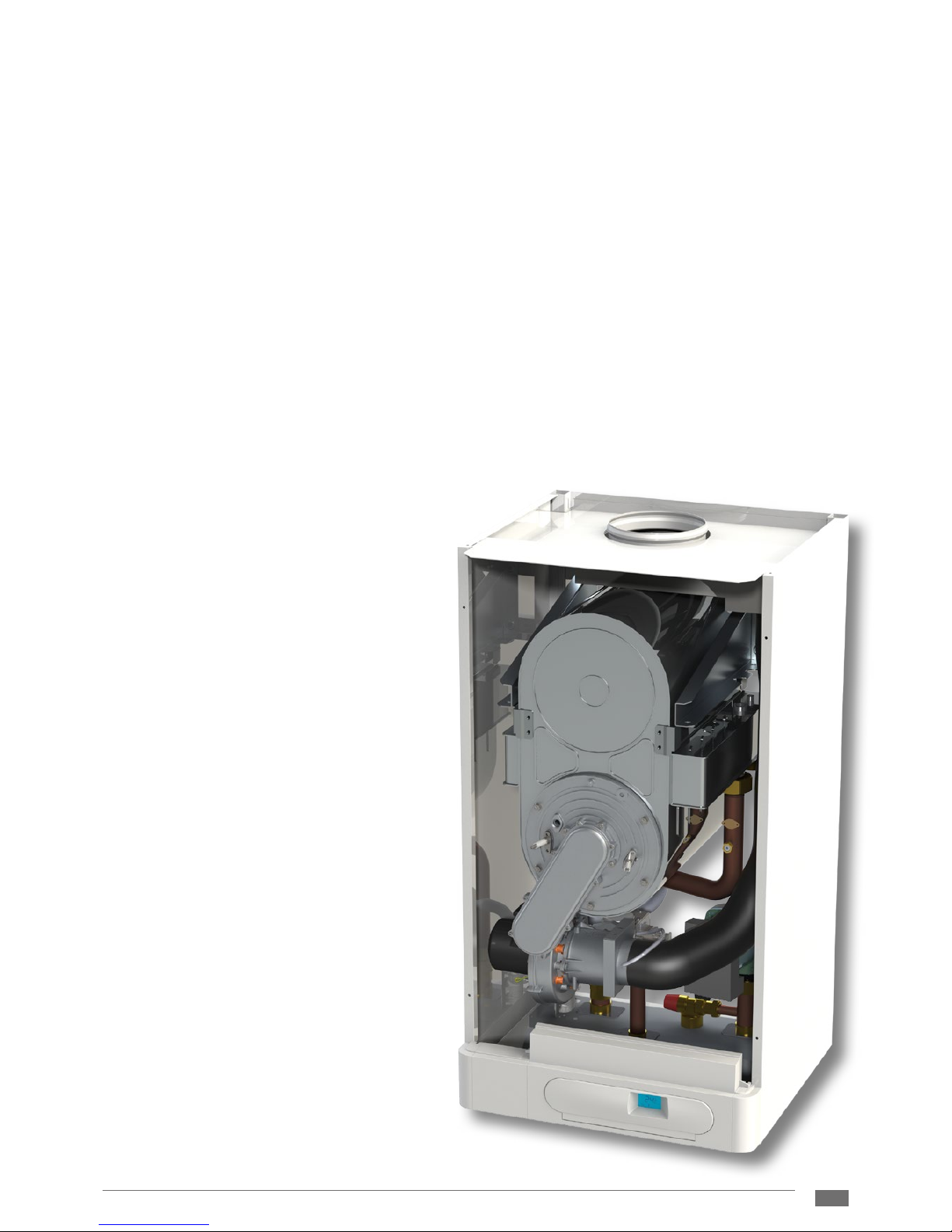
1.2.3 General description
The gas condensing boiler THERM 90 KD.A consists from support frame, which houses all operating elements of the boiler.
Upper part of the boiler houses compact stainless condensing element Sermeta, which integrates combustion chamber with
burner and double-chamber vertically stacked stainless exchanger. Housing of the condensing elements is also made from
stainless material, which ensures high temperature resistance and lifetime of the element. The heat transfer surfaces of the
heat exchangers are formed by the round-shaped tube sheets, which must be protected against dirt deposition from the
heating system. Due to this reason the heating system must be tted with ltering and decanting device at inlet of the returnwater to the boiler (such as spiro-valve). Temperature sensors are located at the input and output collector of heating water
on the element. Removable front burner wall of the element is made from the aluminium alloy, is tted with two electrodes
(burning and ionizing), tube burner an shaped piping for supply of the gas-air mixture.
The gas-air mixture ratio is prepared by compact assembly of pre-mix fan, mixer and gas valve. The mixture is created by
the mixer in conjunction with the special gas valve. It consists of agas pressure regulator, two solenoid blocking valves and
ratio regulation of the output volume of gas with elements for mechanical setting. Adjustment of synchronism of the ratio
regulation is possible only with special device (ue gas analyser). The whole system operates so that the volume of added
gas is directly proportional to the volume of air through the mixer delivered with the ventilator. Therefore it can be stated
that the output on the boiler depends on the volume of the air ow for combustion.
As aresult, the revolutions of the ventilator are uently controlled within awide range which ensures the high output range
of the boiler. The air is supplied into the ventilator is through the shaped piping from the connection system.
Condensate from the condensing element, ue gas exhaustion piping and air inlet is discharged by the hoses to the siphon,
from which the condensate is passed outside the boiler.
Supply of the combustion air, incl. forced extraction of the ue gases, is ensured usually by the coaxial piping, which passes
horizontally through the perimeter wall or vertically
through the roof structure to the free area. It is
necessary to install the piping to prevent (due to the
low temperatures of burnt gases) the possibility of
the freezing of the exhaust terminal. Vertical piping
must terminate at the roof chimney, horizontal with
aslight slope into the exhaust from the boiler.
Power saving transfer pump Wilo ensuring owing
of water through the boiler is installed at the inlet of
the return water. Sucient ow and pressure of the
heating water are monitored by the ow and pressure
switch. In addition, the boiler is tted with the safety
valve for the boiler overpressure protection. Further,
the boiler can be supplemented with suitable motordriven three-way valve for splitting of functions of
the hot water heating and warming of the heating
system.
The control panel is completely plastic. The controls
are located at the front side. The integrated singleplate automatic HDIMS20-TH20 contains electronic
circuits for ignition of burner and for microprocessor
control of the boiler operations.
6
THERM 90 KD.A
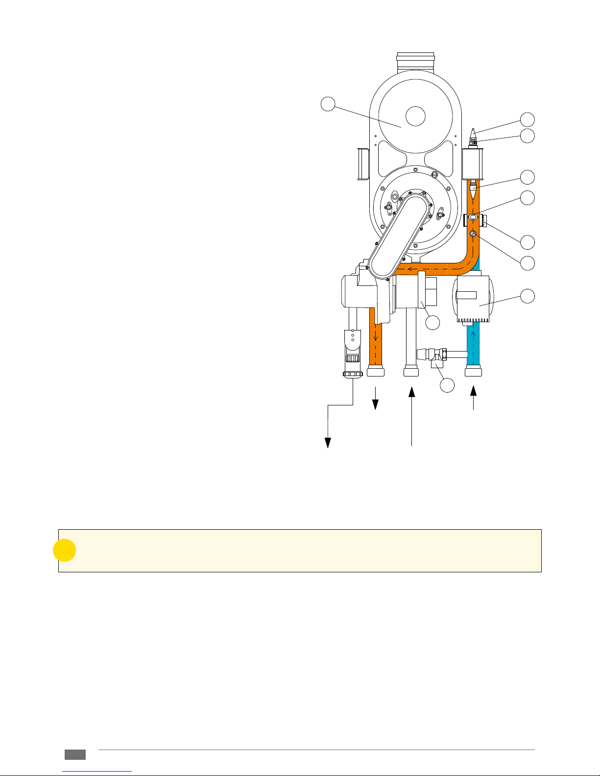
1.2.4 Simplied hydraulic diagram and functional diagram (is not source material for assembly)
THERM 90 KD.A
1 - Preparation of mixture
2 - Safety valve
3 - Circulation pump
4 - Flow switch
5 - Condensing body
6 - Emergency thermostat
7 - Thermal probe
8 - Pressure switch
9 - De-aerating valve*
In the case of gas odour:
- close the gas valve under the boiler
- ensure ventilation of the room (windows, door)
- donot manipulate the electric switch
- liquidate any naked ame
- immediately call service (the boiler must not be used until after the service inspection)
In the case of an odour of combustion burnt gases:
- disconnect the boiler
- ensure ventilation of the room (windows, door)
- call service (the boiler must not be used until after the service inspection)
In the case of aconsumer appliance re:
- close the gas valve under the consumer appliance
- disconnect the consumer appliance from the electricity network
- liquidate the re with powder extinguishing equipment or afoam extinguisher
!
THERM boilers are tted with all safety, emergency and protective elements to ensure completely safe boiler
operation. If irrespective of this, e.g. due to unprofessional intervention, irregular inspections and revisions of
the boiler, etc., there is anon-standard status then we recommend proceeding as follows:
1.3 Operational safety
1
2
3
4
5
6
7
8
7
9
HEATING WATER
OUTPUT
GAS
INPUT
HEATING WATER
INPUT
CONDENSATE
OUTPUT

7
THERM 90 KD.A
Technical description Unit THERM 90 KD.A
Fuel - natural gas
Consumer appliance category - I
2H
Nominal thermal input power kW 89.70
Minimum thermal input power kW 24.20
Nominal heat output at
Δt = 80/60 °C kW 88.70
Δt = 50/30 °C kW 95.00
Minimal thermal output by Δt = 50/30 °C kW 25.60
Gas overpressure on the consumer appliance input mbar 20
Consumption of gas m
3.h-1
2,57 – 9,52
Maximum overpressure of heating system bar 4.0
Minimum overpressure of heating system bar 0.8
Maximum input pressure of cold water °C 80
Diameter of coaxial of exhaust for burnt gases mm 110 /16 0
Average temperature of burnt gases °C 50
Temperature of glue gases in overheated condition °C 82
Lower ue gas temperature at minimum thermal power °C 25
Weight ow of burnt gases g.s
-1
10,2 – 42,8
Weight ow of ue gases at minimum thermal power g.s
-1
10.2
Usable over-pressure of the ventilator Pa 195
CO
2
volume concentration % 8,7 – 9,0
Acoustic pressure level dB (A) 62
Boiler eciency % 98 – 106
NOx class of boiler - 5
Type of electricity supply - ~
Nominal supply voltage / frequency V/ Hz 230 / 50
Nominal current of the circuit breaker for consumer appliance A 2
Auxiliary electricity at
nominal heat input power W 288
partial loading W 198
emergency status W 3
Level of coverage of electrical part - IP 41 (D)
Environment according to ČSN 332000 – 3 - basic AA5 / AB5
Dimensions of boiler: height / width / depth mm 970 / 530 / 500
Weight of boiler kg 85
1.4 Technical parameters
8
THERM 90 KD.A
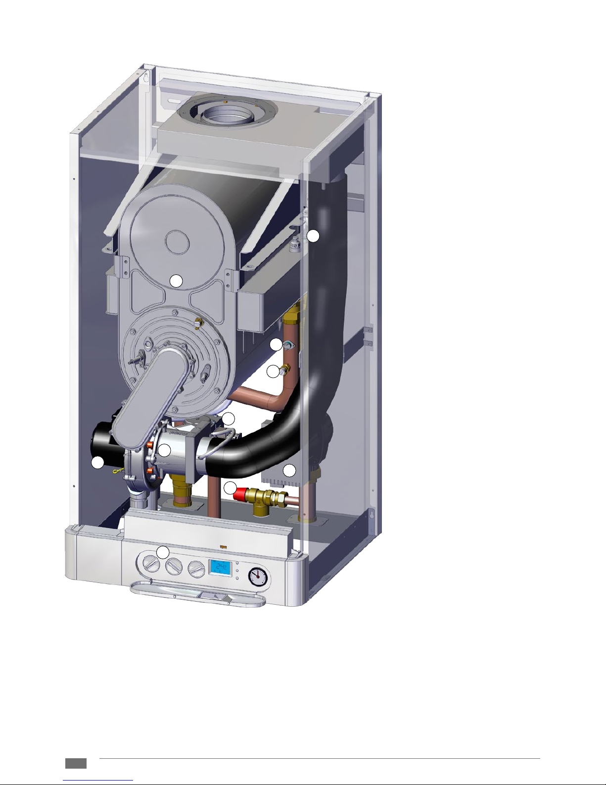
1.5 Set of boiler
THERM 90 KD.A
1 - Condensing chamber
2 - Ventilator
3 - Heating temperature probe
4 - Mixer
5 - Emergency thermostat
6 - Circulation pump
7 - Gas valve
8 - Safety valve
9 - Control panel
10 - Pressure switch
2
5
8
3
6
9
1
4
7
10
9
THERM 90 KD.A
2.1 Control and signalling
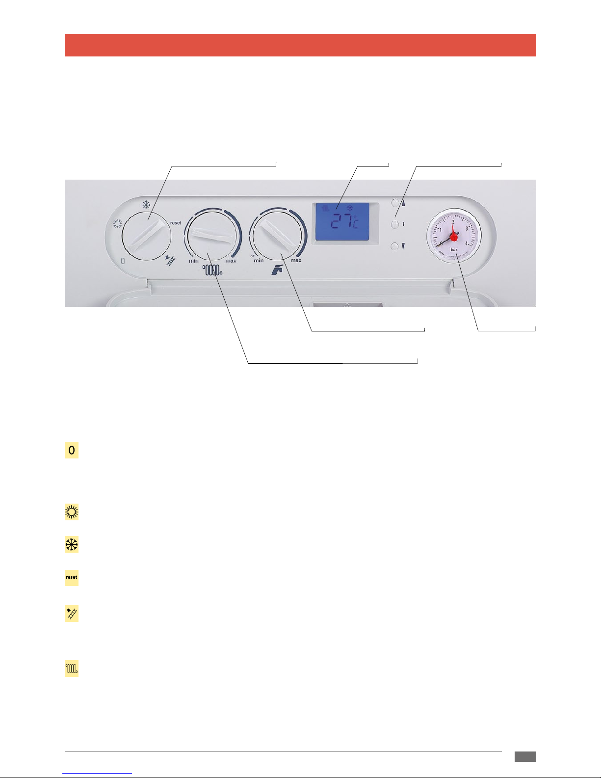
2.1.1 Boiler control panel
Control elements of the boiler are hidden under the plastic cover. The cover is opened by lightly gripping the handle in the
upper part or by pressure on the lower part of the hole for the display.
2. USER MANUAL
The switch for operating regimes has the following positions
Disconnection of the boiler – the protective functions of the boiler remain in operation (when the boiler is connected
to the electricity network and the gas supply is opened). If selecting this mode, the boiler display only indicates the
pressure in the heating system, the heating is disconnected, there is heating of DHW and, at the same time, the backlit
display is OFF.
Summer regime (only heating of DHW is ON, the heating is OFF)
Winter regime (heating and heating of DHW is ON)
Unblocking the failure status of the boiler
Service mode (the function “sweeper“ – the output of the boiler can be uently regulated by the wheel – left position
= minimum output and temperature, right position = maximum output and temperature). This regime serves only for
service activity and measurement (emissions, temperatures of burnt gases, etc.)
Setting the heating temperature – rotary control knob for user setting of the output temperature of water in the
heating system within the range 30 – 80 °C. In the case of selected equitherm regulation, the shift in the heating curve
is set by the control knob (within the range ± 15 °C from the equithermal curve)
temperature of heating water (shift of equithermal curve)
pressure meter
displaySwitch for operating regimes
multifunctional buttons
disconnection of water heating
10
THERM 90 KD.A
Multi-functional buttons – designated for the diagnostics and setting of he parameters of the boiler exclusively by
aservice technician or for switching o information data (see below)
Manometer – displays the measured water pressure in the heating system
Indication of set temperature
After turning the control knob for setting the temperature of the heating system or DHW (boilers with ow heating of DHW)
the respective symbol of the regime will start to ash along with the numeric display of the temperature on the LCD display.
In this case, the value of the last temperature set is indicated. After the termination of the setting, the indication of the set
temperature remains for about 5 seconds. The following permanent display of the numeric value and the symbol, the real
temperature of the respective regime is indicated again.
reset
2.1.2 LCD display
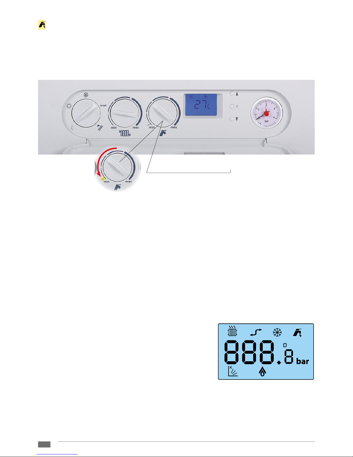
Setting the water temperature – not used, only active when using the machine to heat the solar accumulation reservoir.
The water temperature for THERM 90 KD.A boilers connected to the standard reservoir is set directly on the thermostat
for the reservoir.
Disconnection of water heating – setting the rotary control knob for user setting of the output temperature of the
hot water to the left side position (less than 10° of the route); the heating of water can be in winter mode permanently
disconnected from operation.
option to disconnect the water heating
detail
 Loading...