

ThermoMicroscopes Aurora-2 User Manual

ThermoMicroscopes 85-10316 Rev. A
ThermoMicroscopes
1171 Borregas Avenue
Sunnyvale, California
94089
Tel: (408) 747-1600
Fax: (408) 747-1601
Aurora-2 User’s Manual

ThermoMicroscopes
© 2000 ThermoMicroscopes. All rights reserved.
No part of this publication may be reproduced or transmitted in any form or by any means (electronic or mechanical,
including photocopying) for any purpose, without written permission from ThermoMicroscopes.
Aurora-2, Explorer, and SPMLab are trademarks of ThermoMicroscopes. Others are trademarks of their respective
owners.
ThermoMicroscopes
Binary License Agreement
You, the Licensee, assume responsibility for the selection of the program to achieve your intended results, and for the
installation, use, and results obtained from the program.
IF YOU USE, COPY, MODIFY, OR TRANSFER THE PROGRAM, OR ANY COPY, MODIFICATION, OR
MERGED PORTION, WHOLE OR PART EXCEPT AS EXPRESSLY PROVIDED FOR IN THIS LICENSE, YOUR
LICENSE IS AUTOMATICALLY TERMINATED.
LICENSE:
You may:
Use the program on a single machine and copy the program into any machine-readable or printed form for backup or
support of your use of the program on the single machine.
Modify the program and/or merge it into another pr ogr am for yo ur use on t he sing le machine. Any port ion of the program merged into another program will continue to be subject to the terms of this Agreement. You must reproduce
and include the copyright notice on any copy, modification, or portion merged into another program.
Transfer the program and license to another party within your organization if the party agrees to accept the terms and
conditions of this Agreement. If you transfer the program, you must at the same time either transfer all copies, whether
in machine-readable form or printed form, to the same party or destroy any copies not transferred; this includes all
modificati o ns and po rt io ns of th e pr og r am merge d int o o the r p ro g ram s . You may not transfe r t h e pr og r am to a par ty
outside of your organization without the express written permission of ThermoMicroscopes.
TERM:
The license is effective on the date you take delivery of the software as purchased from ThermoMicroscopes, and remains in effect until terminated as indicated above or until you terminate it. If the license is terminated for any reason,
you agree to destroy or return the program together with all copies, modifications, and merged portions in any form.
April, 2000

Aurora-2 User’s Manual
Table of Contents
Preface
Introduction .............................................................................................................................................v
About this manual....................................................................................................................................v
Operating Safety.........................................................................................................................................vi
ThermoMicroscopes Product Warranty................................................................................................. vii
Chapter 1 Theory of Operation
NSOM Theory.....................................................................................................................................1-1
NSOM Tips..........................................................................................................................................1-1
Distance Control Mechanisms............................................................................................................. 1-2
Modes of Operation.............................................................................................................................1-3
Chapter 2 Aurora-2 Overview & Set-Up
Instrument Overview...........................................................................................................................2-1
Aurora-2 Package....................................................................................................................................2-3
Standard Components..........................................................................................................................2-3
Optional Equipment............................................................................................................................. 2-4
Installation................................................................................................................................................2-4
Instrument Location Considerations................................ ...................................................... .............. 2-4
Cable Connections...............................................................................................................................2-5
Powering Up the System.....................................................................................................................2-5
The Aurora-2 Head..................................................................................................................................2-8
Placing the Head on the Stage........................................................................................................... 2-10
Removing the Head........................................................................................................................... 2-11
Mounting the Sample on the Stage..................................................................................................... 2-11
Installing a Probe................................................................................................................................... 2-11
Aurora Control Unit.............................................................................................................................. 2-15
Optics Controls...................................................................................................................................... 2-16
Transmission Objective.....................................................................................................................2-16
Rotating Mirror..................................................................................................................................2-17
Reflection Objective..........................................................................................................................2-17
Flipper Mirrors ..................................................................................................................................2-18

iv
Optics Set-up ..........................................................................................................................................2-18
Coupling the Laser into the Fiber.......................................................................................................2-18
Inserting a Fiber in the Coupler...................................................................................................2-20
Coarse Adjustment ...................................................................................................................... 2-21
Fine Adjustment .............................................................. ......... ...................................................2-21
Coupling the Laser Light into the Probe............................................................................................2-21
Optical Train Alignment ....................................................................................................................2-22
Chapter 3 Takin g a Topographic Image
Procedure Overview.............................................................................................................................3-1
Approaching the Sample.........................................................................................................................3-2
Finding the Resonant Drive Frequency................................................................................................3-2
Moving the Tip into Feedback.............................................................................................................3-3
Taking a Topography Scan .....................................................................................................................3-5
Optimizing the P-I-D Settings..............................................................................................................3-5
Ending a Topography Session..............................................................................................................3-7
Chapter 4 Taking an NSOM Scan
Checking Feedback Parameters .............................................................................................................4-1
Approaching the Sample and Taking a Scan........................................................................................4-2
Ending an NSOM Session......................................................................................................................4-3
Chapter 5 Counter Board Operation
Introduction..........................................................................................................................................5-1
Hardware Set-Up......................................................................................................................................5-1
Counter Set-Up.........................................................................................................................................5-2
TTL Out .......................................................................................... .....................................................5-2
Integration Time....................................................................................... ......... ...................................5-3
Bi-Directional.......................................................................................................................................5-3
Divider..................................................................................................................................................5-3
Operational Considerations ....................................................................................................................5-3
Appendix: Collection Mode

Aurora-2 User’s Manual
CHAPTER
Preface
INTRODUCTION The Aurora-2 is a Near-field Scanning Optical Microscope ( NSOM). NSOM is an optical
microscopy technique that offers higher resolution limits than confocal microscopy.
Because NSOM combines optical and scanning probe microscopy, sample surface
chemistry can be imaged and analyzed simultaneously with surface topography measurements. The ability to gather topographic data while producing an optical image is useful in
material characterization and analysis.
It is important to read this manual and be familiar with the Aurora-2 instrument to facilitate
more productive and efficient use of NSOM as a research tool.
ABOUT THIS
MANUAL
Chapter 1 provides an overview of the theory of NSOM and how it is applied in the
Aurora-2 instrument. Chapter 2 descr ibes the Aurora-2 instrument componen ts and set-up.
Chapters 3 and 4 provide step-by-step instructions for taking a topographic scan and an
NSOM scan, respectively, of the standard sample.
This manual covers those aspects of the SPMLab software that are specific to the Aurora2 configuration. Fo r a tho rough unders tanding of how t o us e the sof tware, t he user shou ld
refer to the SPMLab Software Reference Manual.
vi
85-10316 R
EV. A
OPERATING SAFETY
All W arning and Caution statements in this manual should be strictly observed. Failure to
do so may result in serious injury, particularly blindness due to exposure to laser light, and
damage to your Aurora-2 instrument.
Warning statements—indicated by this symbol—alert you to possible serious injury, especially blindness due to laser light exposure. Procedures in this manual must be follo wed
exactly. Do not proceed beyond a warning until the conditions of the warning are understood and met.
Caution statements—indicated by this symbol—call attention to poss ibl e dama ge to the
system or to the impairment of safety unless procedures described in this manual are
followed exactly.
WARNING NEVER LOOK DIRECTLY INTO THE LASER BEAM.
These labels are placed on the Aurora-2 to warn you of the danger of laser light. Exposure
to laser light is possible at the laser, at the end of the laser fiber, at the probe tip, or at any
point on the fiber-optic cable if it should break. Follow all set-up and operation procedures
in this manual carefully.
DANGER
LASER LIGHT
AVOID DIRECT
EYE EXPOSURE

PREFACE vii
Aurora-2 User’s Manual
THERMOMICROSCOPES PRODUCT WARRANTY
COVERAGE
ThermoMicroscopes warrants that products manufactured by Thermo Microscope s will be
free of defects in materials and workmanship for one year from the date of shipment. The
product warranty provides for all parts (excluding consumables and maintenance items),
labor, and software upgrades.
Instruments, parts, and accessories not manufactured by ThermoMicroscopes may be
warranted by ThermoMicroscopes for the specific items and periods expressed in writing
on published price lis ts or quotes . However , all such warranties ext ended by ThermoMicro scopes are limited in accordance with all the terms, conditions, and other provisions stated
in this warranty. Ther moMicroscopes makes no warranty whatsoever concern ing products
or accessories not of its manufacture except as noted above.
Customers outside the United States and Canada should contact their local ThermoMicroscopes representative for warranty information appropriate to their locale.
CUSTOMER RESPONSIBILITIES
1. Perform the routine maintenance and adjustments specified in ThermoMicroscopes’
manuals.
2. Use ThermoMicroscopes replacement parts.
3. Use ThermoMicroscopes or ThermoMicroscopes-approved consumables, such as
lamps, cantilevers, filters, etc.
4. Provide adequate and safe working space around the products for servicing by
ThermoMicroscopes personnel.
REPAIRS AND REPLACEMENTS
ThermoMicroscopes will, at its option, either repair or replace defective instruments or
parts. Repair or replacement of products or parts under warranty does not extend the
original warranty period. With the exception of consumable and maintenance items, replacement parts or products used on instruments out of warranty are themselves warranted
to be free of defects in materials and workmanship for 90 days. Any product, part, or
assembly returned to ThermoMicroscopes for examination or repair must have prior
approval from ThermoMicroscopes and be identified by a Return Materials Authorization
(RMA) number obtained before returning the prod uct. The product, par t, or assembly must
be sent freight prepaid to the factory by the Customer. Return transportation will be at ThermoMicroscopes’ expense if the produc t, part, or ass embly is def ective and under wa rranty.
WARRANTY LIMITATIONS
This warranty does not cover: a) Parts and accessories which are expendable or cons umable
in the normal operation of the products; b) Any loss, damage, and/or product malfunction
resulting from shipping or storage, accident, abuse, alteration, misuse, or use of usersupplied software, hardware, replacement parts, or consumables other tha n those specified
by ThermoMicroscopes; c) Products which are not properly installed; d) Products which
are not operated within the specified environmental conditions; e) Products which have

viii
85-10316 R
EV. A
been modified or altered without written authorization from ThermoMicroscopes; f)
Products which have had the serial number alter ed or removed; g) Im pro per or inad equ a te
care, maintenance, adjustment, or calibration by the user.

Aurora-2 User’s Manual
CHAPTER
Chapter 1
Theory of Operation
NSOM THEORY Historically, the limiting factor in optical microscopy has been the diffraction limit of light.
Attempts to image features approximately the size of a wavelength of light met with frus-
tration because of diffraction. As far back as the 1930’s, a theoretical solution to this
problem was suggested.
1
However, it was not until the early 1980’s that the electronic
control and feedback capability existed to realize this solution.
2
If the aperture exposing
the sample is kept very small—on the order of 50 nm—and the aperture is kep t close to the
sample surface—generally less than 20 nm—the diffract i on problems can be avoi ded. It
was not until the development of scanning probe microscopes, however, that technology
existed to maintain such close tip-sample spacing while a tip was being scanned over a
sample.
NSOM TIPS The light source in an NSOM system is launched into an optical fiber . The end of the fiber
is “pulled down” to a diameter of 5 0 nm. Th e fiber is then coated with alum inum, app rox imately 100 nm thick. The fiber b ecomes a “light funnel” directing light onto the sample.
Photodetectors are placed behind the sample (transmission mode) or besi de the tip (re flection mode) to collect light emitted from the sample. A laser is used as a light source and is
coupled into the back side of the NSOM fiber-optic probe.
1. E.H. Synge: A Suggested Model for Extending Microscopic Resolution into the Ultramicroscopic Region. Phil.
Mag. 6, 356-36 2 (1928).
2. D.W. Pohl, W. Denk, and M. Lanz: Optical Stethoscop y:
Image Recording with Resolution 1/20. Appl. Phys. Lett. 44,
No. 7, 651-653 (1984).
1-2
Figure 1-1 Fi ber-Optic Probe Tip
DISTANCE
CONTROL
MECHANISMS
Tip geometry alo ne is not enough to produce images. The tip must also be very clos e to the
sample, typically <10 nm. These small separations are only possible with electronic
position detection and control. Distance control is currently achieved using a shear-force
mechanism. Two such mechanisms exist: light-lever and tuning fork. For these techniques, the tip is attached to a vibrating element wh ich is d riven at its res onant f requ ency.
This vibration is parallel to the surface. As the tip approaches the surface, the vibration
amplitude and phase change. This change in amplitude and phase generates an electrical
signal that is input into the feedback loop.
The Aurora-2 uses the tuning fork mech anis m fo r dis tance co ntro l, as it has the ad van tag e
of producing an electrical signal directly, rather than relying on another dev ice to generate
a signal. This direct connection provides better feedback control, uses much smaller
vibration amplitudes, and does not introduce unwanted light into the sample area.
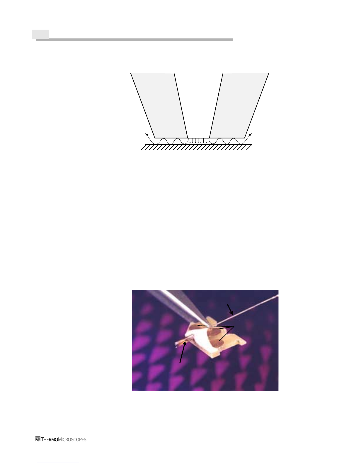
Figure 1-2 Aurora-2 Fiber-Optic Probe
Sample Surface
Fiber
Aluminum
coating
Aluminum
coating
100nm 50nm
Tuning fork
Contacts
Fiber
THEORY OF OPERATION 1-3
Aurora-2 User’s Manual
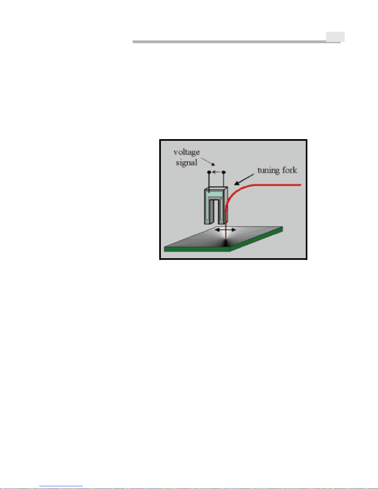
The fiber-optic probe is attached to one prong of a piezoelectric tuning fork. The tip
extends slightly beyond the end of the tuning fork. The tuning fork is vibrated using a
dithering piezoelectric device, which produ ces a vi brational amp litude at the tip of app roximately one nanometer. As the piezoelectric material of the fork vibrates, it produces a
small current. The vibration amplitude of the fiber can then be measured by measuring th e
piezoelectric signal from the tuning fork. The current is amplified and inp ut into a lock-in
amplifier. The phase change of the tuning fork signal relative to the driving signal is
measured and used in the feedback loop.
Figure 1-3 Tuning Fork Mechanism
MODES OF
OPERATION
The NSOM instrument is a unique combination of a scanning probe microscope and an
ultra-high resolution optical microscope. Generally both modes—topography and
optical—are used together. However, there may be some situations where topography is
used alone.
The NSOM, used as an optical microscope, can be operated either in tip collection or tip
illumination mode. In tip collection mode, the sample is the light source, and the tip acts
as a way to collect this light. This method is best for samples such as waveguides and laser
diodes.
Tip illumination mode is perhaps the most common NSOM mode. Tip illumination uses
the tip as a “light funnel” to illuminate the sample in a precise, controlled manner. This
mode can be further subdivided into reflection collection, transmission collection, and li-
thography modes. Reflection collection gathers light that has been reflected from the
sample. It is used for opaque samples, such as semiconductor materials. This method is
not as efficient for gathering light, since the physical position of the tip collector does not
allow it to collect much of the reflected light. Reflection mode might also suffer from
image artifacts created by tip shadowing on the sample surface. Transmission mode is
more commonly used and is more ef f icient. T he collector is p laced behind the sample and
collects a majority of the light as it passes through the sample. The drawback to this mode
is that it requires the use of thin, transparent samples.

1-4
There are a number of operational techniques in transm ission mode. The major techniques
are bright field, fluorescence, polarization, and spectroscopy. These techniques use
different properties of light. Bright field mode is similar to standard optical microscopy in
that the sample is exposed to light from the NSOM probe, and the resulting image is
recorded by detecting all wavelengths, including the source light, on the photomultiplier
tube (PMT). In fluorescence modes, the tip is used to excite the sample, and any resulting
fluorescence is captured and imaged. Polarization mode typically polarizes the incoming
light and looks at how the sample changes that polarization. In spectroscopy techniques,
the signal is the change (either time-scale or wavelength) the sample causes in the exposing
light. Figure 1-4 illustr ates the relationships between these operational modes.
Figure 1-4 NSOM Operational Modes
Examples of NSOM imaging with the Aurora, using the modes referenced in Figure 1-4,
are included in the following literature.
1. P.J. Moyer, T. Cloninger, J. Gole, and L. Bottomley. Experimental evidence for
molecule-like absorption and emission of porous silicon using near-field and far-field
optical spectroscopy. Phys. Rev. B, 60, No. 7, 4889-4896 (1999).
2. P.F. Barbara, D.M. Adams, and D.B. O’Connor. Characterization of organic thin film
materials with near-field scanning optical microscopy (NSOM). Annu. Rev. Mater. Sci.,
29, 433-46 9 (1999).
3. A. Naber, H. Kock, and H. Fuchs. High-Resolution Lithography with Near-Field
Optical Microscopy. Scanning Vol. 18 (8), 567-571 (1996).
4. Ch. Lienau, A. Richter, A. Klehr, and T. Elsaesser. Near-Field Scanning Optical Microscopy of Polarization Bistable Laser Diodes. Appl. Phys. Lett. 69, No. 17, 2471-2473
(1996).
Optical
&
Topography
Tip
Collection
Tip
Illumination
Sample Types
Waveguides
LED's
Diode lasers
Reflection
Transmission
Opaque Samples
Semiconductors
Bright field
Fluorescence
Polarization
Spectroscopy
1
2
3
4
Lithography
Aurora-2 User’s Manual
CHAPTER
Chapter 2
Aurora-2 Overview & Set-Up
INSTRUMENT
OVERVIEW
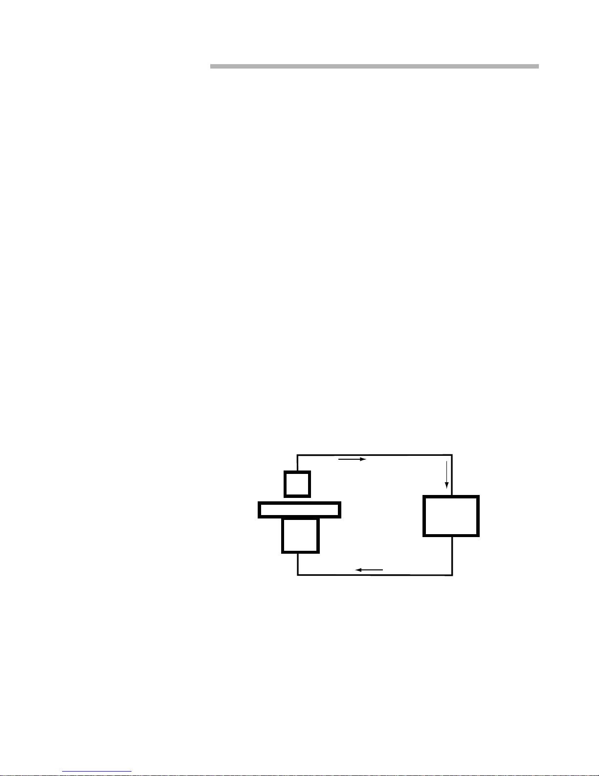
The Aurora-2 instrument is a platform for obtaining topographic and optical images. It
offers a wide variety of configuration options, depending on the desired NSOM imaging
mode. The sample is mounted on a scanning stage which is controlled by a three-piezo
scanner arrangement. The fiber-o ptic probe is mou nted on the remov able Aurora- 2 microscope head and positioned above the sample. T opographic and optical images can be taken
simultaneously.
Figure 2-1 Topography Feedback Loop
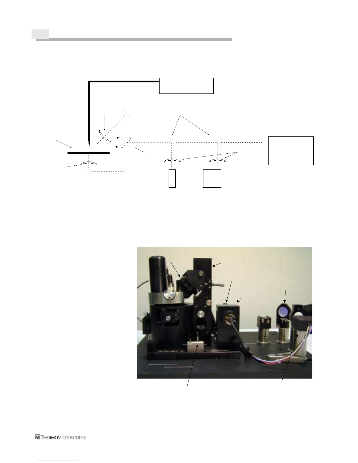
The optical components of the Aurora-2 system are used for taking NSOM data as well as
for focusing the optics and monitoring the probe-sample app roach. The rotating mirror (see
Figure 2-2) selects either the reflection or transmission objective. The two “flipper”
mirrors can be manually flipped down to allow the use of the PMT or optional hardware,
such as a photon counter or spectrometer.
XYZ
Piezo
Sample Stage
Probe
Control
electronics
2-2
.
Figure 2-2 Aurora-2 Light Path
Figure 2-3 Instrumen t Compone nts
Laser & coupler
Photomultiplier
tube (PMT)
CCD
camera
Flipper mirrors
Focusing
lenses
Reflection
objective
lens
Transmission
objective
lens
Stage
Rotating
mirror
Optional
Hardware
Head
CCD Camera
Reflection
tower
PMT flipper
Camera flipper
mirror (hidden)
mirror
Cam splicer
PMT
Reflection
objective
Scanning
Transmission
objective
stage
{
{
&

AURORA-2 OVERVIEW & SET-UP 2-3
Aurora-2 User’s Manual
AURORA-2 PACKAGE
STANDARD
COMPONENTS
All the components of the basic Aurora-2 configuration are listed below. It is a good idea
to go through this list to be sure that all the items have been received. Shipping errors can
be corrected by contacting Customer Service.
• Instrument stage (base plate with mounted hardware)
• Aurora-2 sensor head
• Electronic Control Unit-Plus (ECU-Plus) with I/O 10 and I/O MOD+ boards
• Aurora Control Unit
• Computer
• Video monitor
• NSOM fiber-optic tips
• Probe installation tool
• Fiber cleaver
• Fiber stripper tool
• Tool kit
• Cables
• NSOM standard sample
• User’s Manual
• Instrument enclosure
• SPMLab software
• SPMLab Software Reference Manual
OPTIONAL
EQUIPMENT
• I/O-U input/output board
• I/O-P photon counter board
• Laser
• Laser coupler
• Daughter board for additional analog-to-digital conversion channels
• Explorer SPM head
• Vibration isolation table
The Explorer SPM head is a popular option, as it uses the same control hardware as the
Aurora-2. The User-Access board (I/O-U) provid es access to most of the input and monitor
signals on the ECU-Plus. The photon counter interface board (I/O-P) allows the user to
collect data through a photon count er, which is usef ul for very low light le vels. Contact th e
ThermoMicroscopes representative in your area for more information on these options.
2-4
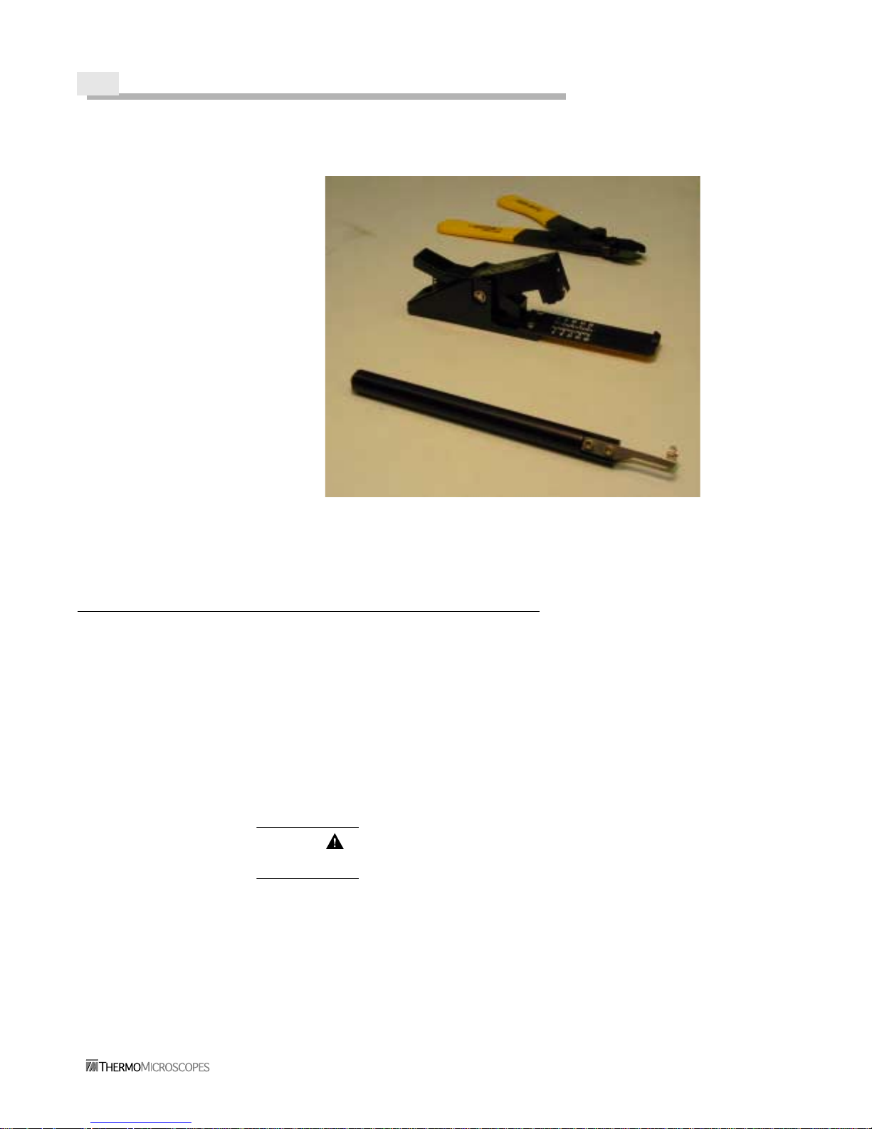
Figure 2-4 Probe and Fiber Tools
INSTALLATION
INSTRUMENT
LOCATION
CONSIDERATIONS
The Aurora-2 should be mounted in an environment that is as vibration-free as possible.
Sources of mechanical and acoustic vibration will decrease the Aurora’s maxi mum re solu tion capability. The Aurora-2 should be placed on a its own vibration isolation table.
Computer cooling fans and mouse click s pr odu ce vi brati on that negati vely i mp acts image
quality, so place the computer on a separate table. Basement or ground floor rooms are
better for the instrument, since multi-story buildings usually have sig nificant vibration on
the upper floors. Temperature and humidity should be controlled to maintain constant environmental conditions. Normal indoor conditions, i.e., “room temperature” and average
humidity, are sufficient. Extremes of temperature and humidity will negatively affect the
instrument and possibly cause damage.
CABLE
CONNECTIONS
CAUTION Make sure the power is OFF to all the modules and the computer while
setting up. Connecting cables to powered-up electronics may damage the modules.
The cable connection diagrams (Figure 2-5 and Figure 2-6) show the configuration with
and without an external lock-in amplifier (a lock-in amplifier is also integrated into the I/O
MOD+ board). A photocopy of the appropriate diagr am is useful for checking of f the cable
connections as they are made.
Probe installation tool
Fiber stripper
Fiber cleaver
AURORA-2 OVERVIEW & SET-UP 2-5
Aurora-2 User’s Manual
POWERING UP
THE
SYSTEM
WARNING To prevent serious injury, make sure the cover is on the laser coupler
before turning the laser on. Follow all safety warnings when powering up and using the
laser.
CAUTION Make sure the PMT voltage is turned all the way down (to the counter-
clockwise limit) before powering up the components.
Once all the connections are made, the components can be powered up. First turn on the
ECU-Plus, then the computer and the video monitor. (The ECU-Plus should always be
turned on before the computer so that the ECU interface is recognized and initialized.) The
laser is powered up separately. Power is automatically applied to the Aurora Control Unit
when the ECU-Plus is powered up.
 Loading...