

Thermomax THX-DL User & Installation Manual
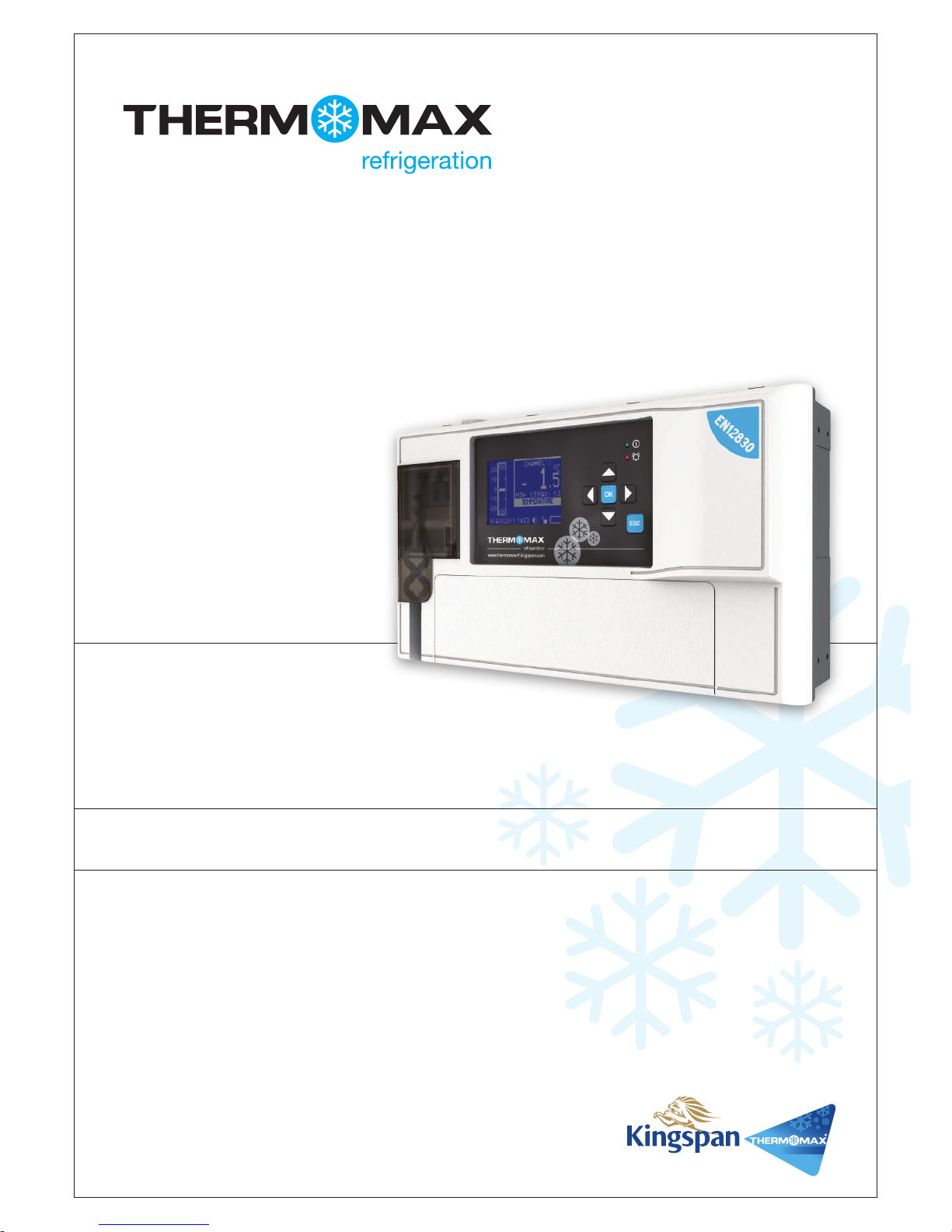
USER & INSTALLATION MANUAL V3.2016
www.thermomax-refrigeration.com
THX-DL
Data Logger
Refrigeration
TempControl
|
3 2 | TempControl
Contents
PRESENTATION
Summary of Features 2
INSTALLATION
Safety Precautions 4
THX Unit 4
Sensors 4
Alarm Relay 4
Power Connection and Wiring Diagram 5
Battery
5
Wall & Panel Mount 6
Panel Mount diagrams 7
New Email Connectivty Setup 8
THX OPERATION
1.0 Summary Screens 10
1.1 Sensor Summary 10
1.2 Door Summary 11
1.3 Alarm Summary 11
1.4 Daily Min / Max 12
2.0 Channel View 12
3.0 Alarm Settings 13
4.0 Settings
4.1 Set Clock 14
4.2 Alarm Mute Setup 14
4.3 Channel On / Off 15
4.4 Sensor Type 15
4.5 Door ON / OFF 16
4.6 Door Setup 16
4.7 Relay Setup 17
4.8 Relay Normally Closed / Normally
Open Setup 17
4.9 Calibration 18
4.10 Network 19
5.0 Plot
5.1 Current Day 19
5.2 History 20
6.0 Service Screen
6.1 Test 21
6.2 Contrast 21
6.3 Keypad 21
6.4 Relay 22
7.0 Language Select 22
8.0 Sample Period 23
9.0 Unit Information 23
10.0 Diagnostics
10.1 Databank 24
10.2 Channel 24
USB
1. Download Data 25
2. Download Setup 26
3. Upload Setup 26
4. Service 26
WEB SERVER 27
1. Live Data 28
2. Status 28
3. Setup 29
4. User 30
5. Time 30
6. Graph 31
7. Network 31
SPECIFICATION 32
Presentation
SUMMARY OF FEATURES
Datalogger
• Temperature /humidity from each Channel can be set to
sample every 1/5/15/30/60 minutes and stored to an internal
databank
• Up to 12 channels of data logging can be employed using the
module configuration
• Power Supply 100 – 240V AC Mains
• Contents of internal databank can be transferred to the USB
Flash Memory and viewed or transferred to the PC via website
• Universal panel mount or wall mount box
• Expandable modular design
• IP54 Rated
• Battery Back-up up to 6hrs
• Backward compatible with old sensors (PT 100 terminated
with RJ 11)
• EN12830 certified
• CE tested
• On Board Web Server (IP addressable)
• Large data storage capacity
• USB Firmware Upgrade Functionality
• Module Auto-Detect and self-configuration
• Door Alarm Configuration Function (4 doors per module)
Alarm
• 2-Stage high and low level alarms with mute facility
• Stage 1 temperature threshold with trigger delay
• Stage 2 limit temperature with immediate trigger
• Alarm history record for low alarm, high alarm and power fail
• Battery back-up for power-fail operation
• Summary screen for Alarm Overview
Note: The information supplied in this manual is for guidance only – no part
of this may be used for any agreement, whether express or implied, or to
form any contract.
BACK
BOX
FRONT
COVER
FRONT LID
COMMS. AREA

TempControl
|
5 4 | TempControl
Installation
Note: This installation procedure is for guidance only, and its suitability should be verified by the installer.
SAFETY PRECAUTIONS
= WARNING! - Information which is essential for preventing hazard to personnel or device and must be read with care.
= DANGER! - High voltage area. Isolate power supply before any maintenance work.
The following safety precautions are strongly recommended:
1. Before attempting to install and operate the unit, read the instruction and installation manual carefully.
2. Installation and any maintenance should only be carried out by suitably qualified personnel.
3. It is recommended that the unit be connected to the mains supply via a suitably rated isolating switch.
4. WARNING: When the unit is connected to the mains supply and the cover is open, the circuits at mains voltage will be
exposed. Therefore when installing the unit, ensure all required connections (including battery connected, if included), are made and
covers replaced before turning on the mains supply. Ensure that all the connections made are secure. If any maintenance work e.g.
installing a new battery, is required ensure that the unit is isolated from the mains supply before removing the cover. Never leave the
unit unattended if the cover has been removed and the mains supply is connected.
5. Do not exceed unit ratings as shown on the ratings label.
6. It is advisable to route mains cables away from low voltage or sensor cables.
(i) THX Unit
Note: For viewing comfort, the unit should be positioned at eye level. The ambient temperature of the unit is (0°C to +40°C). It is always good practice to keep
electronic equipment away from cold, heat and electrical plant, as extremes of temperature may reduce the lifetime of the device, and heavy electrical loads,
switches, relays or contactors too close to the device may cause electrical and electro-magnetic interference when switched on or off.
(ii) Sensors
The THX may be used with a variety of sensors of different cable lengths. If required, sensors are available with extended cable lengths or
alternatively, sensor extenders are available also in a variety of lengths. If the sensors need to be extended, but factory-made extenders are
not available, they can be extended using a suitable 3 or 4 core cable, according to the diagram shown below
Please note however, that as with all PT100 sensor applications, a good connection is vital. It is therefore recommended that wherever there
is any doubt, a factory extended sensor or sensor extender should be used.
(iii) Alarm Relay
Note: The alarm relays are 2 contact arrangements which are isolated (volt-free). These relays may be used to trigger an external bell, warning lamp or digital
communicator (telephone dialler).
Max rating of Alarm relays is 5A @ 240 VAC.
The alarm relay is software configurable to accommodate normally open or normally closed operation, as described below.
Normally Closed Operation – This is the default mode.
Normally Open Operation – In this mode, the relay outputs will break contact (open circuit) in the event of an alarm and make contact
(closed circuit) in the event of power failure.
If the external device is used, connect the alarm as appropriate, according to the diagram opposite.
Installation
(iv) Power Connections and Wiring Diagram
Note: This device should be properly earthed. Flexible wires simplify connection to the terminals. All connections should be secure and adequately tightened.
It is good practice to keep mains cables away from sensor cables and other low voltage signal cables.
Connect the supply to the unit, as per diagram below, using the appropriate input voltage according to the application.
(v) Battery
The battery supplied is a 3.7V Lithium-polymer rechargeable battery and is plugged in but switched OFF. This should be switched ON
after installation. See picture below. This battery is not essential for the system operation, but is used in the case of power failure, thereby
continuing to log the 12 sensor inputs for approximately 6 hours.
The system parameters will remain intact, in the event of a power failure, however all interface options (Ethernet, screen, keypad options,
USB etc. will not function as normal)
It is recommended that the battery is changed every 24 months, in order to maintain good power failure backup operation. When replacing,
ensure that the type of rechargeable battery used is as specified.
(3.7V Lithium-polymer rechargeable battery)
WHITE
RED
BLUE
GREEN
GROUND
SENSE
COMPENSATE
TempControl
|
7 6 | TempControl
Installation
WALL MOUNT
1. Drill four holes in the wall, according to the template and insert
the wall plugs
2. Remove the Front Lid by unscrewing two screws
3. Disconnect the modules
4. Separate the front cover by unscrewing two screws
5. Remove the required knock outs from Back Box for the cables
to pass through (always separate front cover before removing
the knock outs)
6. Insert the cable glands
7. Screw in the Back Box to the wall
8. Pass the cables through the glands
9. Mount the Front Cover on the Back Box
10. Insert the modules
11. Connect the power supply cable and sensors
12. Tighten the cable glands
13. Mount the front lid
- An inlet or insulating liner with a smooth rounded opening
- A cord guard made from an insulating material should be firmly
attached to the device. The insulating material should extend
beyond the inlet by at least five times the overall diameter of
the cord with the largest cross-sectional area that can be
used to supply the device. Where the conductors are
connected inside the device, the cord anchorage will relieve
the conductors of the cord from excessive strain, this includes
twisting. The anchorage must also protect the insulation of
conductors from abrasion. The protective earth conductor
must be the last suffer from any strain in the event the cord
should slip in its anchorage. The anchorage must provide relief
from a pull force of 30 Newton and a twisting or torque force
of 0.10 Newton metres. Cord anchorage shall meet the
following requirements.
WARNING: TO PROTECT THE MAINS SUPPLY LEAD FROM ABRASION AND SHARP BENDS AT THE POINT WHERE
THE LEAD ENTERS THE DEVICE, ONE OF THE TWO FOLLOWING METHODS MUST BE EMPLOYED:
- A screw that comes into direct contact with the cord will not
be used to clamp down the cord.
- The cords will not have any knots tied in it.
- It will not be possible to push the cord into the device to such
an extent that it will cause a hazard.
- Should the cord insulation fail in an anchorage that has metal
parts, none of the exposed conductive material of the device
will become live.
- A compression bushing will not be used as cord anchorage
unless it is capable of accommodating all sizes and types of
mains supply cord that meet the requirements in point (2) and
are suitable for connection to the terminals of the device, or
the bushing has been designed to terminate a screened
mains supply cord.
- The cord anchorage will be designed in such a way that cord
replacement does not cause a hazard and will be clear how
strain relief is provided.
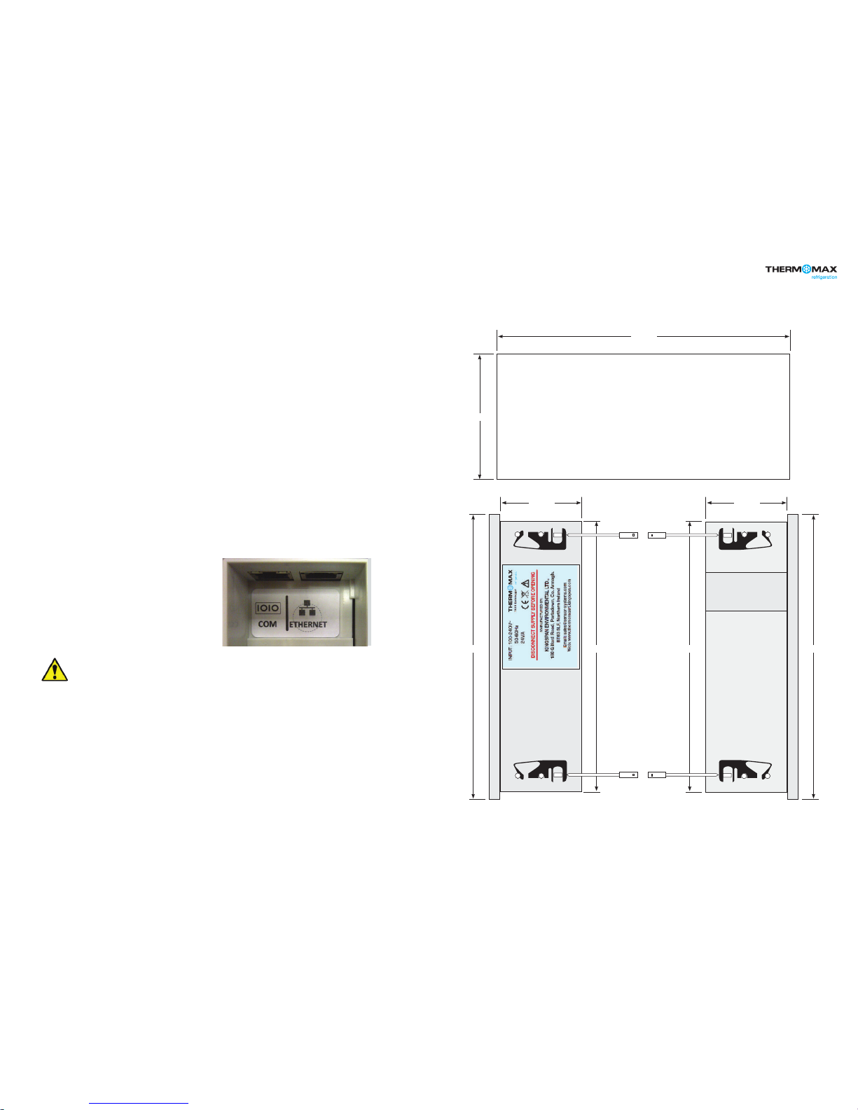
PANEL MOUNT (required panel mount kit)
1. Cut a hole in the panel with the described dimensions,
(see page 7)
2. Remove the Front Lid unscrewing two screws
3. Disconnect the modules
4. Separate the front cover by unscrewing two screws
5. Remove the required knock outs from Back Box for the cables
to pass through (always separate front cover before removing
the knock outs). Ethernet cable can be passed through the
hole which is under the label on the front cover (see picture
below)
6. Attach the Panel Mount Seal, ensure that it is on the right position
7. Insert the Back Box into the panel cut out
8. Attach the four Panel Mount Fixing Clips (supplied), to the four
studs at either side of the unit, (see page 7).
9. Tighten the four Panel Mount Fixing Screws
10. Insert the cable glands
11. Pass the cables through the glands
12. Mount the Front Cover on the Back Box
13. Insert the modules
14. Connect the power supply cable and sensors
15. Tighten the cable glands
16. Mount the front lid
Installation
296mm
50mm 50mm
169mm
177mm177mm 168mm 168mm
Right side view
Panel mount xing clip
Panel mount xing clip
Left side view
Panel mount xing clip
Panel mount xing clip
Panel mount
xing screw
Panel mount
xing screw
Panel mount
xing screw
Panel mount
xing screw
Area required to be cut out for panel mount
TempControl
|
98 | TempControl
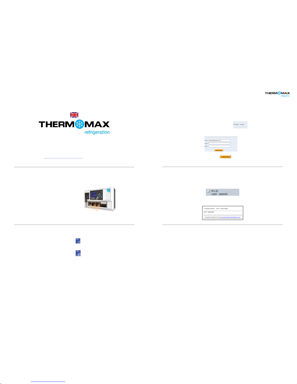
NEW Email connectivity set-up
NEW Email connectivity set-up
Email alert functionality only available on firmware version 1.8 and above.
* Visit http://www.thermomax-refrigeration.com/uk/en to download the latest firmware.
Benefits
• NO SIM REQUIRED
• NO EXTRA HARDWARE NEEDED
• NO ANNUAL FEES TO PAY
• Up to 3 users can be made aware of an
alarm status remotely.
• Easy to install and maintain.
• No need for Auto-Dialer system.
How the new Email Alert functions?
Example: High Alarm threshold set at in settings on THX-DL,
– when the above temperature has been exceeded
– The THX-DL will initiate the Email Alert.
Example: Low Alarm threshold set at in settings on THX-DL,
– when the above temperature has been exceeded
– The THX-DL will initiate the Email Alert.
An Email alert will also be sent in the event of loss of power from the
THX-DL
* It is the customers responsibly to keep power to the network infrastructure.
How do I test the new Email feature ?
Brief Set up summary
• Select Enable on your webserver page.
• Enter the email address/addresses of recipients to be alerted during
alarm sequences - up to 3 recipients can be selected with no
prioritisation.
• Select the Test and Save icon
• A Test Email will be sent to entered Email Addresses.
How will the Email look ?
Example: The Email/Emails will be sent to the inbox displaying the
THX-DL Serial number where alarm has occurred.
Example: The Email will display the channel/channels where the alarms
have occurred.
PC: CPU 2.0GHZ or above
Memory Size: 256MB or above
Display Card: 64M or above
Supported OS: Microsoft Windows XP/Vista/Win7 or above, Mac OS
Browser: IE8 and above version or compatible browser, Firefox or
other standard browsers. Java environment required to
view webpage.
Connectivity:
Network and Internet connection
Opened (non-encrypted) port for outgoing emails (25, 2525, 587)
Technical Support: Telephone: +44 (0) 28 3836 4460
Connectivity and networking minimum
requirements:
TempControl
|
11 10 | TempControl
THX-DL Operation
In order to fully understand the operation of the unit, this section should be read carefully.
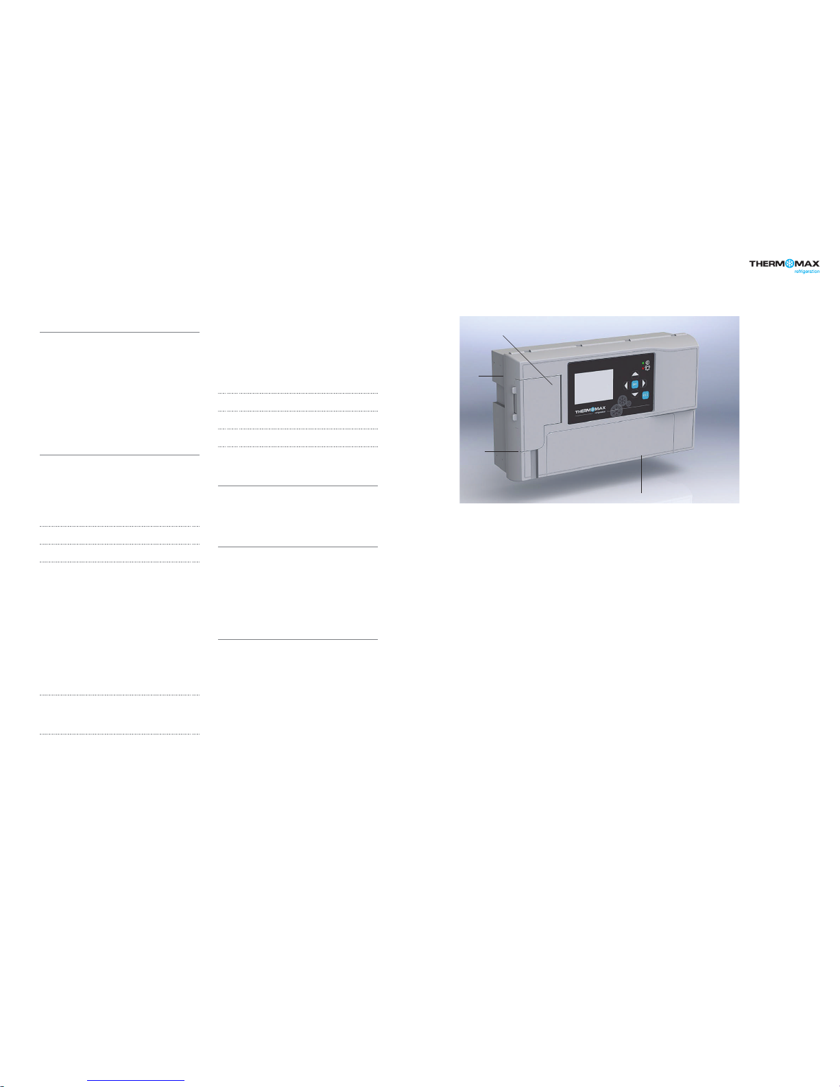
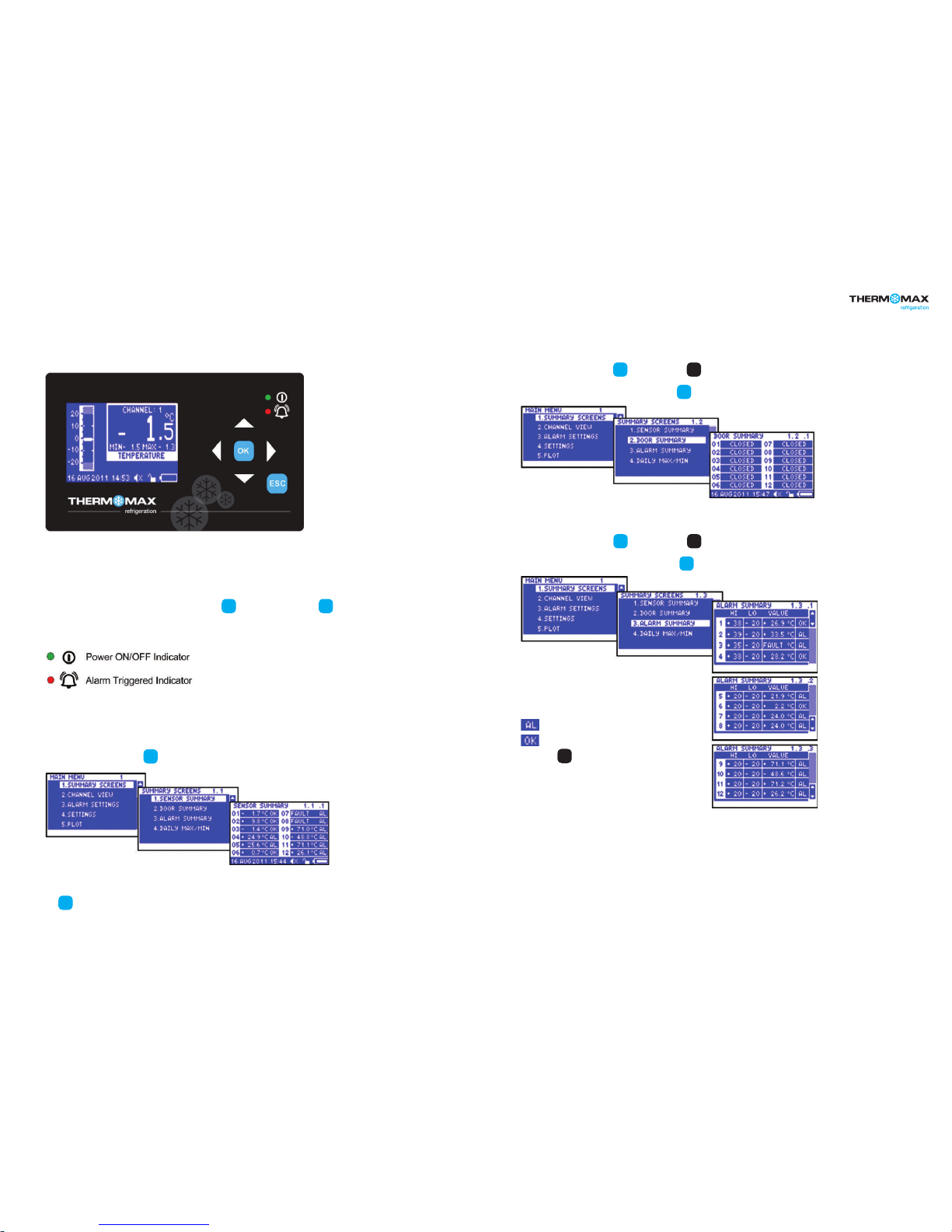
(i) Graphic LCD Display
Displays all the information. The contrast is adjustable to suit the user. (Refer to section 6.2)
(ii) Function Keys
The six keys are used to navigate through the unit’s menus, allowing for easy access to the THX many options and settings.
The four arrow keys select an option in the displayed menu, the key select the menu and the key returns to the previous menu.
A menu I.D. is displayed at the top of each screen to indicate to the user which particular menu is being addressed.
(iii) Indicators
1.0 SUMMARY SCREENS
These screens allow the user to view all the data logged by the unit for each channel, e.g. Sensor Summary, Door Summary, Alarm
Summary, and Daily Max/Min Temperatures.
1.1 Sensor Summary
From the Main Menu screen, press key twice to reveal the Sensor Summary Screen.
This screen displays the current temperature/humidity readings of each of the connected channels and indicates if that channel
is in alarm or not.
The key will return the user to the previous menu option.
1.2 Door Summary
From the Main Screen, press the key, followed by the key to select
Door Summary in the menu. Confirm selection using the key to reveal the Door Summary Screen.
This screen displays the status of each of the 12 digitals inputs, indicating whether it is OPEN, CLOSED or OFF. (Default status is OFF)
1.3 Alarm Summary
From the Main Screen, press the key, followed by the key to select
Alarm Summary in the menu. Confirm selection using the key to reveal the Alarm Summary Screen.
These screens display the High and Low Alarm Limit settings for
each channel and also display the current temperature/humidity
readings. The sensor’s status is also displayed, i.e., in alarm or ok.
alarm limit or alarm threshold has been reached
no alarms
Pressing the key will reveal information for channels 5 to 8,
and pressing once more, reveals information for channels 9 to 12.
THX-DL Operation
ESC
ESC
OK
OK
OK
OK
▼
OK
OK
▼
▼
 Loading...