

Thermomax SM QUATTRO User Manual
THERMOMAX
SM QUATTRO
4 - CHANNEL DATALOGGER AND ALARM
ENGLISH
THERMOMAX
3
4
www.Thermomax-Group.com
CONTENTS
SECTION 1 - INTRODUCTION .................................................……..................... 2
SECTION 2 - INSTALLATION ............................................................….........……. 3
2.1 - SM QUATTRO Unit ........................................................................... 4
2.2 - Sensors ............................................................................................. 4
2.3 - Alarm Relay ......................................................................…............. 5
2.4 - Power Connections and Wiring Diagram ..........................…...... 5
2.5 - Battery .....................................................................................….….. 5
SECTION 3 - OPERATION ..................................................................................…. 6
3.1 - DESCRIPTION ...........................................................................…... 6
3.2 - MAIN SCREENS:
3.2.1 MAIN SCREEN 1: Bar Graph Temperature / Humidity
Display ……........................................................................... 8
3.2.2 MAIN SCREEN 2: Digital Temperature / Humidity
Display .……….....................................…...………….......... 9
3.3 - SET SCREENS:
3.3.1 SET SCREEN 1: Clock / Calendar ..................….............. 10
3.3.2 SET SCREEN 2: System Presets 1 ...............................… 11
3.3.3 SET SCREEN 3: System Presets 2………………............ 13
3.3.4 SET SCREEN 4: Sensor Input Type Selection ……........ 14
3.4 - SYSTEM DIAGNOSTICS:
3.4.1 DATABANK DIAGNOSTICS SCREEN .........……….......... 15
3.4.2 CHANNEL DIAGNOSTICS SCREEN ..............….............. 16
3.4.3 CALIBRATION TRIMMING SCREEN ................................. 17
3.5 - CHANNEL SCREENS: ……
3.5.1 CHANNEL DISPLAY SCREENS ........................................ 18
3.5.2 CHANNEL SET SCREEN - TEMPERATURE ..……........ 19
3.5.3 CHANNEL SET SCREEN – HUMIDITY ………....……... 20
3.6 - CURRENT DAY PLOT: ………………………................……. 21
3.7 - PLOT HISTORY: Data log of previous days: ...................…... 22
3.8 - DATA TRANSFER: ….................................…..................….….. 24
3.8.1 Transferring Data Using the Masterlink software ......... 24
3.8.2 Transferring Data to the Masterlink Hardware .............. 24
3.8.3 Printing Data to the Thermomax Serial Printer ............. 26
3.9 - DATA TRANSFER - Panelmount units Only ................................ 27
SECTION 4 - FAULT FINDING …........................................................................... 31
SECTION 5 - SPECIFICATIONS …..................................................…….............. 32
KEYPAD LOCK …………………………………………………..………............… 33
SM QUATTRO PANELMOUNT ............................................................................... 34
DEUTSCHE BEDIENUNGSANLEITUNG …………………………………....... 36
1

SECTION 1 INTRODUCTION
The SM QUATTRO microprocessor-based datalogger uses the novel approach of a
paperless logging and filing system, which allows the data of any day in its history to
be read and examined with a few key presses.
The large graphics LCD display communicates the information to the user with clarity,
making programming and setting up friendly and uncomplicated, without
compromising its sophistication and digital accuracy.
SUMMARY OF FEATURES
DATALOGGER
• Paperless datalogger with automatic filing by date
• 50-year clock/calendar for datalogger filing.
• The temperature from each Channel is sampled every 15 minutes and stored
to an internal databank.
• ‘Percentage of internal databank used’ indication in bargraph and digital form.
• Power Supply 220 – 240V AC Mains.
• Contents of internal databank can be transferred directly to the PC using the
MASTERLINK Software or via a MASTERLINK Hardware module to a PC at a
remote site.
ALARM
• 2-Stage high and low level alarms with mute and reset facilities,
• Stage 1 temperature threshold with trigger delay.
• Stage 2 limit temperature with immediate trigger.
• Status window for system fault indication.
• Diagnostics screen revealing system parameters.
• Alarm history record for low alarm, high alarm and power fail.
• Battery back-up for power-fail operation.
Note: The information supplied in this manual is for guidance only – no part of this
may be used for any agreement, whether express or implied, or to form any contract.
2

SECTION 2 INSTALLATION
Note: This installation procedure is for guidance only, and its suitability
should be verified by the installer.
SAFETY PRECAUTIONS
The following safety precautions are strongly recommended:
1 Before attempting to install and operate the unit, read this instruction manual
carefully.
2 Installation and any maintenance required should only be carried out by
suitably qualified personnel.
3 It is recommended that the unit be connected to the mains supply via a
suitably rated isolating switch.
4 WARNING: When the unit is connected to the mains supply and the
cover is opened, the circuits at mains voltage will be exposed. Therefore
when installing the unit, ensure all required connections (including battery
connection, if included), are made and covers replaced before turning on the
mains supply. Ensure that all the connections made are secure. If any
maintenance work e.g. installing a new battery, is required ensure that the
unit is isolated from the mains supply before removing the cover. Never
leave the unit unattended if the cover has been removed and the mains
supply is connected.
5 Do not exceed unit ratings as shown on the ratings label.
6 It is advisable to route mains cables away from low voltage or sensor cables.
3
2.1 SM QUATTRO UNIT
NOTE: For viewing comfort, the SM QUATTRO unit should be positioned at
eye level. It is always good practice to keep electronic equipment away from
cold, heat and electrical plant, as extremes of temperature may reduce the
lifetime of the device, and heavy electrical loads, switches, relays or
contactors too close to the device may cause electrical and electro-magnetic
interference when switched on or off.
2.1.1 Knock out the entries into the moulding to be used for connection, either
behind or under the moulding, whichever is suitable for the particular
installation.
2.1.2 Fasten the screw corresponding to the top centre lug on the back of the SM
QUATTRO moulding, into the wall or panel on which the unit is to be
mounted. Leave a gap of approximately 3mm between the screw head and
the wall. Position the moulding and slot in the lug over the screw.
2.1.3 Level the SM QUATTRO moulding and, if using rear entry, mark the entry
holes in the panel behind the appropriate knock-out entries, as well as the
two lower mounting holes. Remove the moulding, drill the necessary holes in
the panel, assemble any grommets or conduit adapters if used, replace the
moulding and fasten using the two lower screws.
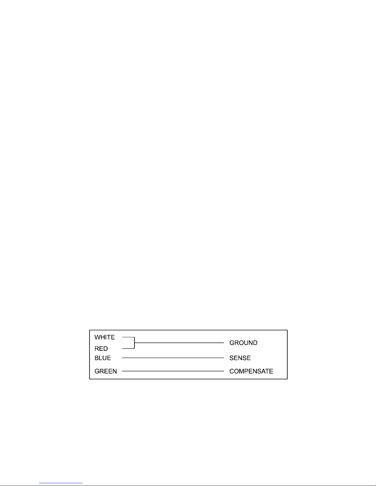
2.2 SENSORS
The SM QUATTRO may be used with a variety of sensors of different cable
lengths. If required, sensors are available with extended cable lengths or
alternatively, sensor extenders are available, also in a variety of lengths. If the
sensors need to be extended, but factory-made extenders are not available,
they can be extended using a suitable 4 core or 3 core cable, according to
the diagram shown below.
Please note however, that as with all PT100 sensor applications, a good
connection is vital. It is therefore recommended that wherever there is any
doubt, a factory- extended sensor or sensor extender should be used.
4
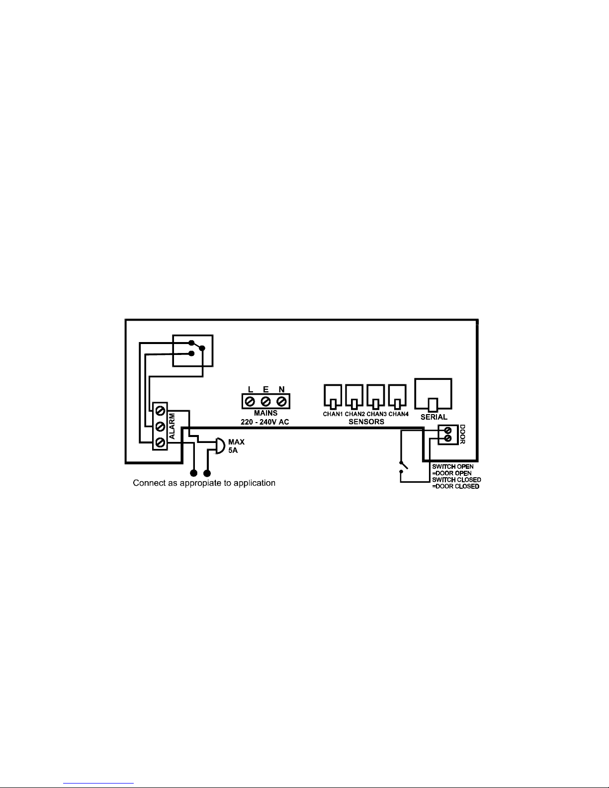
2.3 ALARM RELAY
NOTE: The alarm relay is a 3 contact changeover arrangement which is
isolated (volt-free). This relay is normally energised, and switches off when
the alarm is triggered, or in the case of power failure. It may be used to
trigger an external bell, warning lamp, or digital communicator (telephone
dialler).
If an external device is used, connect the alarm as appropriate, according to
the diagram in the next section.
2.4 POWER CONNECTIONS AND WIRING DIAGRAM
NOTE: This device should be properly earthed. Flexible wires simplify
connection to the terminals. All connections should be secure and adequately
tightened. It is good practice to keep mains cables away from sensor cables
and other low voltage signal cables.
Connect the supply to the unit, as per diagram below, using the appropriate
input voltage according to the application.
2.5 BATTERY
The battery supplied is a 9V PP3 nickel metal hydride rechargeable battery
and is attached to the lid of the terminal compartment, but not plugged in.
This should be plugged in after installation. This battery is not essential for
the system operation, but is used in the case of power failure, thereby
continuing to log the four input temperatures for 3 – 4 hours, and maintaining
the system clock.
If the power cut takes longer and the battery is discharged, the clock must
be set when the power supply is re-established. The system parameters
remain intact.
It is recommended that the battery is changed every 12 months, in order to
maintain good power failure operation. When replacing, ensure that the type
of battery used is as specified.
5
SECTION 3 SM QUATTRO OPERATION
In order to fully understand the operation of the SM QUATTRO, this section should
be read carefully.
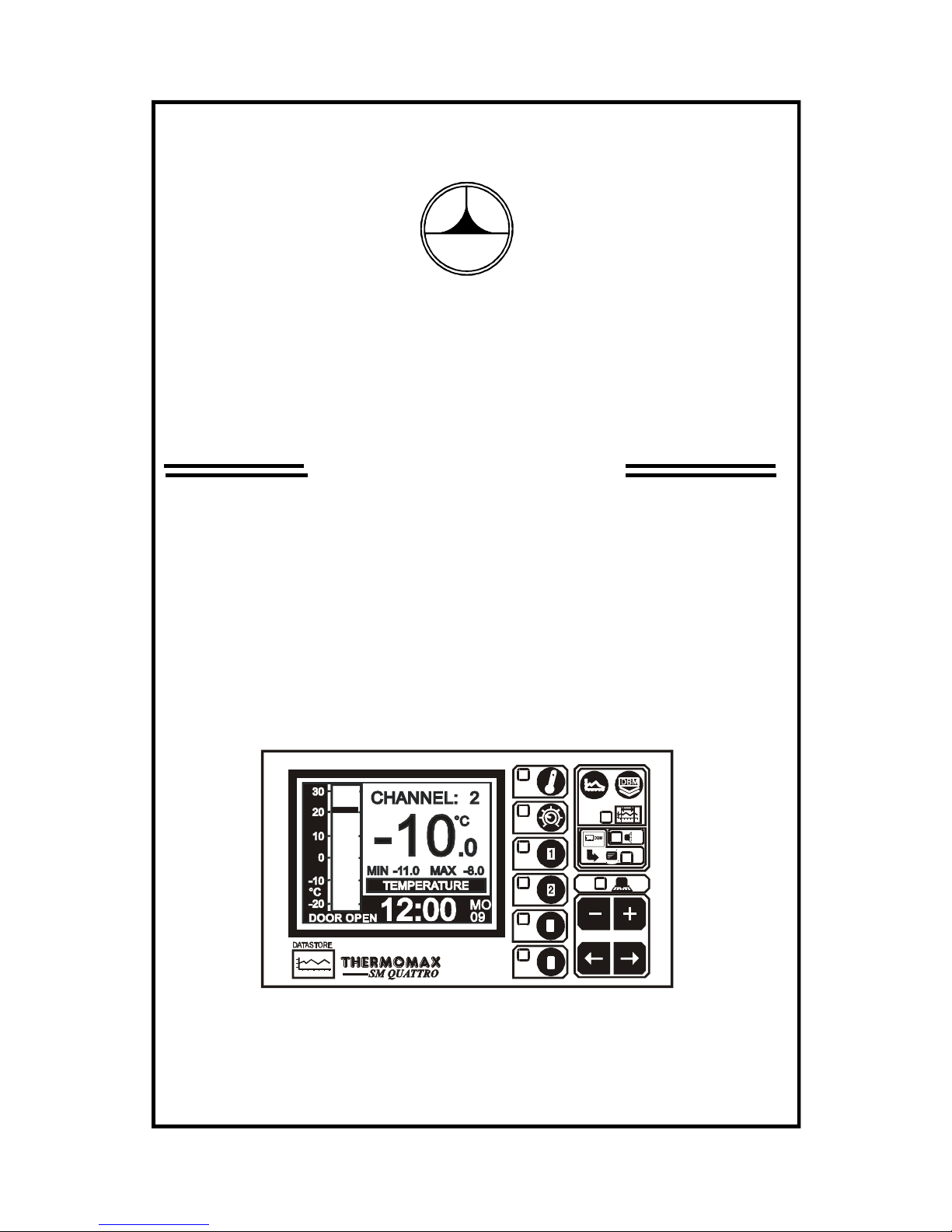
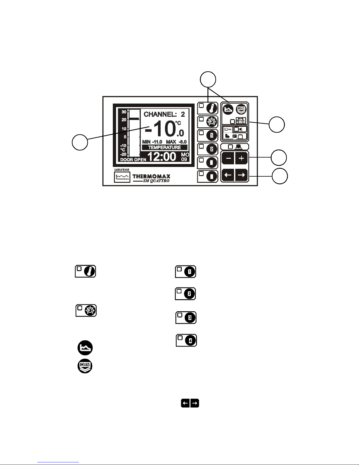
3.1 DESCRIPTION
THERMOMAX
3
4
1 GRAPHICS LCD DISPLAY
Displays all the information. The contrast is adjustable to suit the user. (See
3.2.1 Main Screen 1).
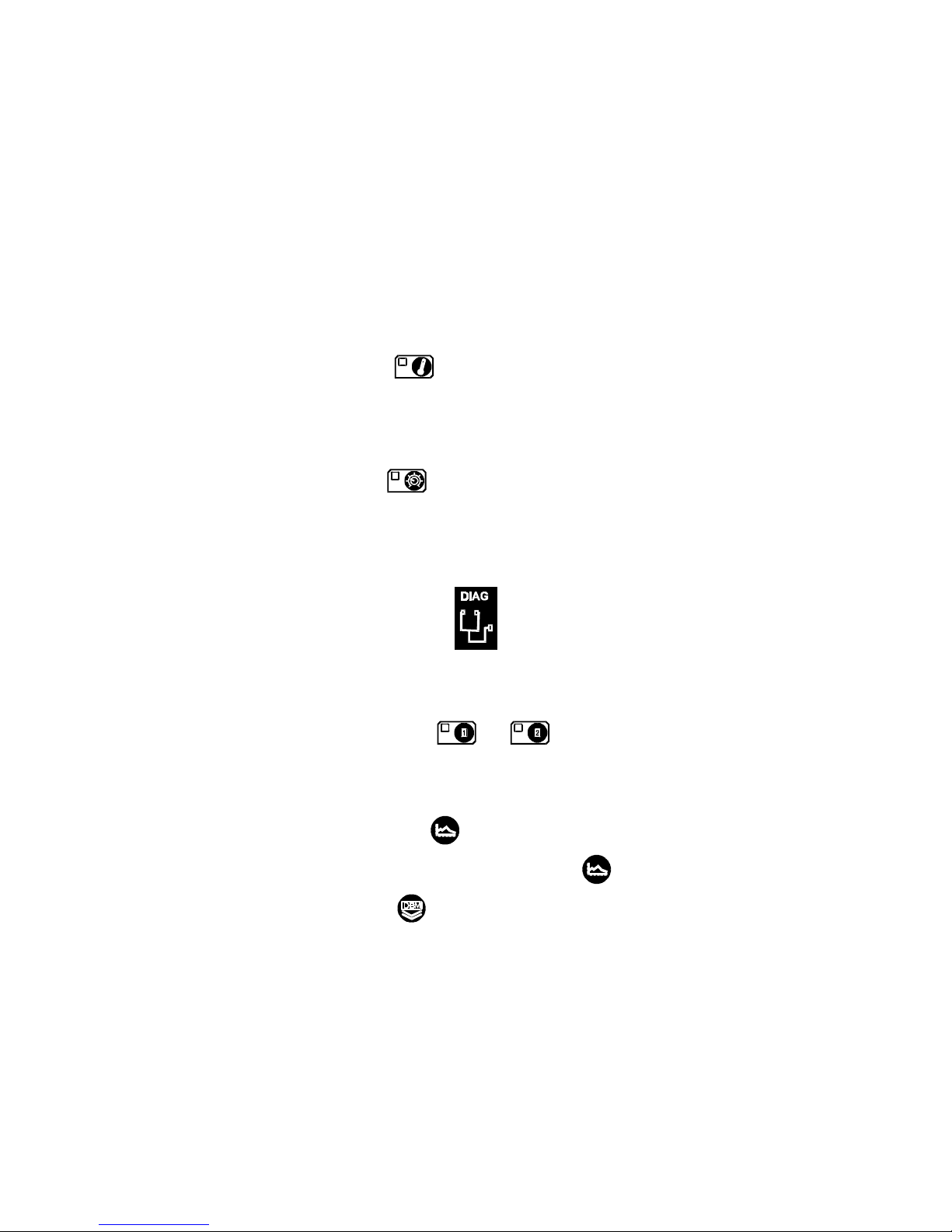
2 FUNCTION KEYS
There are eight function keys on the SM QUATTRO datalogger:
- Main Screen 1 - Channel 1 Display Screen
- Main Screen 2 - Channel 1 Set Screen
- Channel 2 Display Screen
- Channel 2 Set Screen
- Set Screen 1
- Set Screen 2 - Channel 3 Display Screen
- Set Screen 3 - Channel 3 Set Screen
- Set Screen 4
- Channel 4 Display Screen
- Current Day Plot - Channel 4 Set Screen
- Plot History Screen
- Data Transfer Key
3 SELECT KEYS
Within each function, there are some parameters that can be selected for
setting or displaying purposes. The keys allow the required parameter
to be chosen, without changing any of its properties.
6
4
2
1
5
3

7
4 SET KEYS
The and keys are used to set the value of any selected parameter, by
increasing and decreasing the value respectively.
In most of the functions, described later in the manual, the and keys
have an auto-repeat facility: press and hold the key in order to advance
quickly.
Note: The and keys are the only keys which can alter the value of a
selected parameter. Other keys may be pressed to view or select these
parameters without effecting any change in the system.
5 INDICATORS
The System Alarm can be triggered by the high temperature alarm, low
temperature alarm, or by a sensor fault.
INTERNAL DATABANK
DATA TRANSFER IN PROGRESS
SYSTEM ALARM
8
3.2 MAIN SCREENS
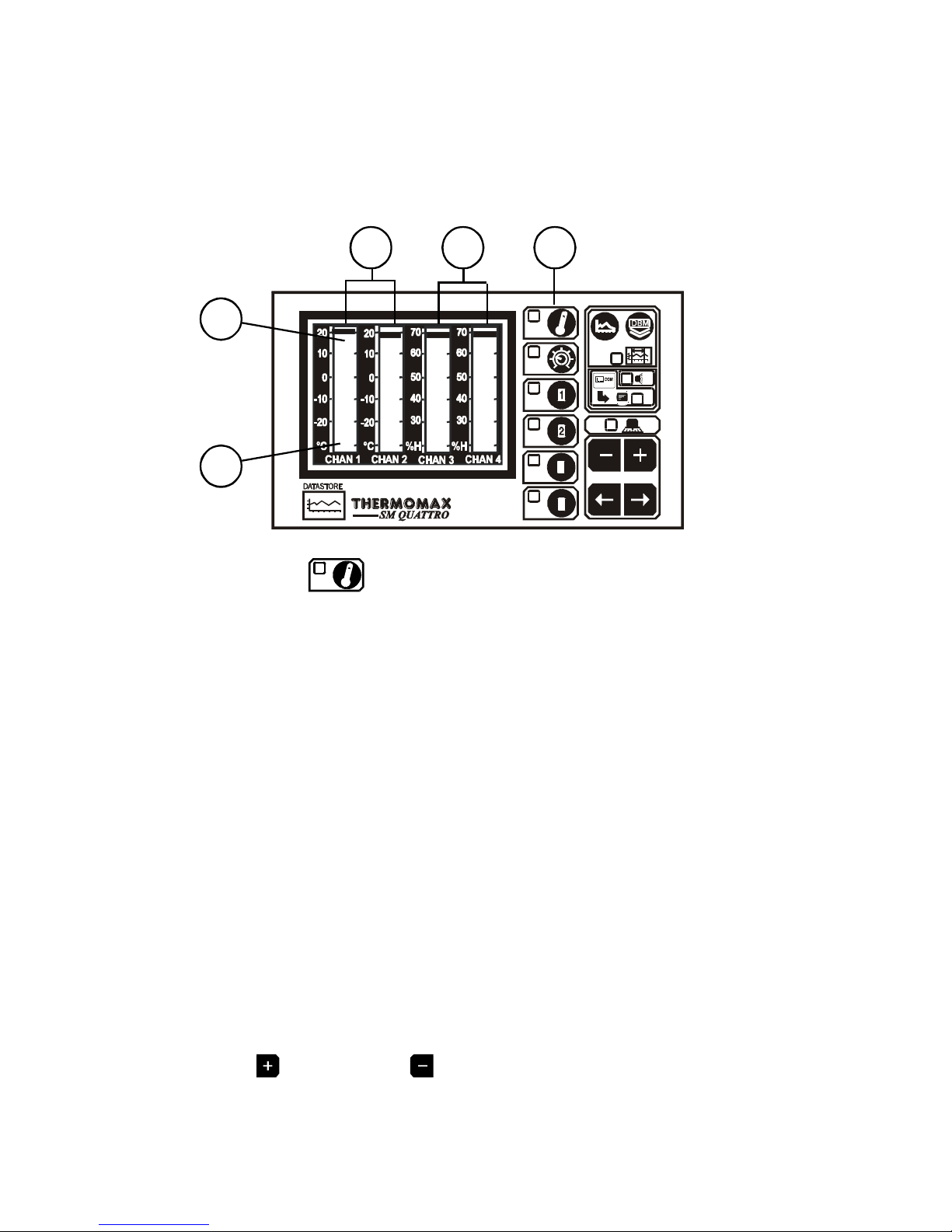
3.2.1 MAIN SCREEN 1: BAR GRAPH TEMPERATURE / HUMIDITY DISPLAY
This screen allows the user to view the information for each channel in
bargraph form and is shown below. The high and low Temperature / Humidity
limits are shown on these bargraphs and are represented by the shaded
areas.
THERMOMAX
3
4
Pressing the key the first time will display the MAIN SCREEN which
shows a four channel bargraph display as shown above.
2 Channels 1 & 2 in this example display temperature.
3 Channels 3 & 4 display relative humidity in this example.
4 This shaded area shows the High Alarm Limits (Stage 2 Alarm).
5 This shaded area shows the Low Alarm Limits (Stage 2 Alarm).
Note 1:
In this example configuration, channels 1 & 2 are connected to temperature
sensors and channels 3 & 4 are connected to humidity sensors, therefore the
bargraph for channels 3 & 4 displays relative humidty (%H). (See section
3.3.4).
Note 2:
See Section 3.5.2 “Channel Set Screens” for more information on
temperature Alarms, and section 3.5.3 for information on Humidity Alarms.
Note 3:
The display contrast may be adjusted in this screen.
Press to increase and to decrease the contrast.
To adjust quickly, press and hold for auto-repeat.
4
5
2 3 1
9
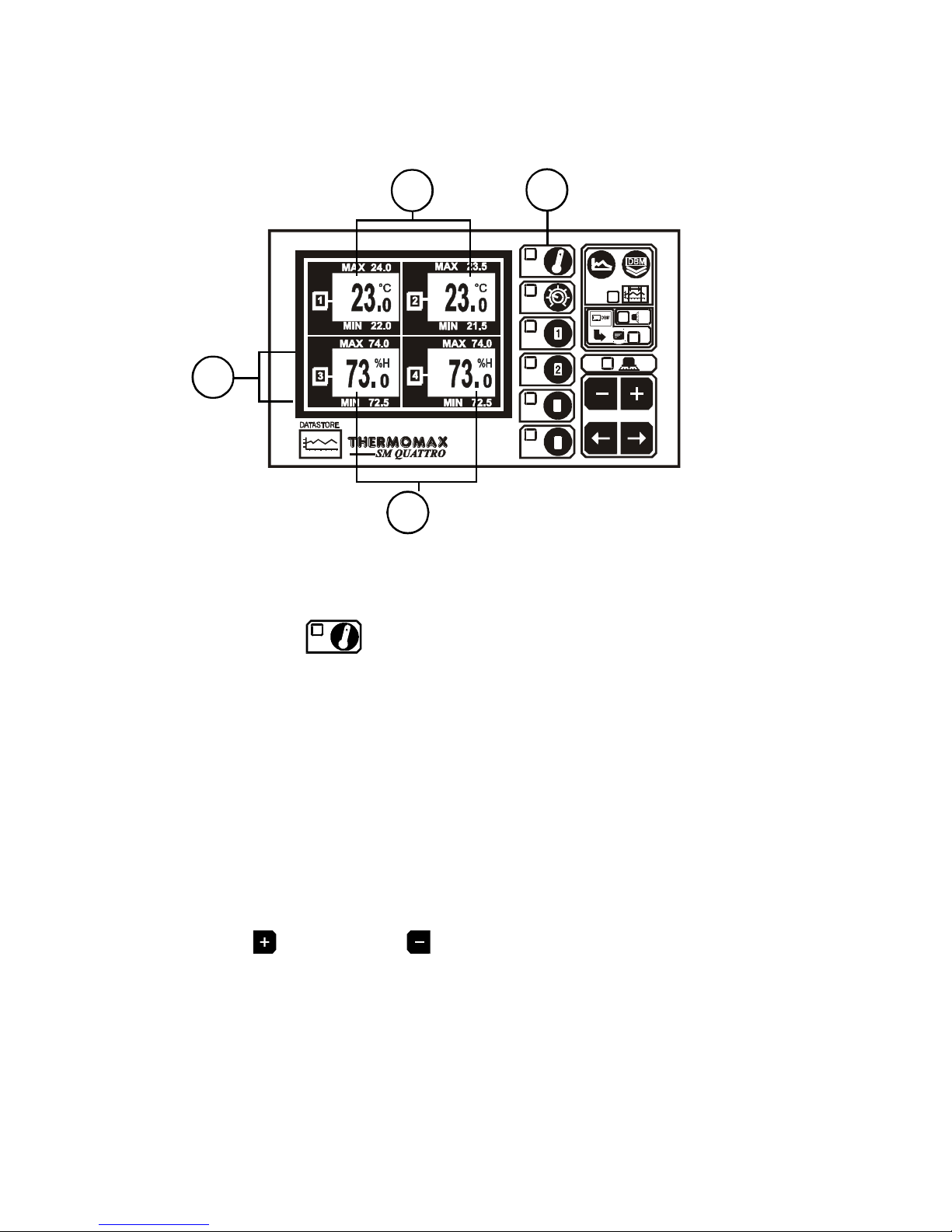
3.2.2 MAIN SCREEN 2: DIGITAL TEMPERATURE / HUMIDITY DISPLAY
1 MAIN SCREEN function selector.
Pressing the key a second time reveals the screen above.
2 Current temperature for channels 1 & 2.
3 Current humidity reading for channels 3 & 4.
4 Maximum and minimum daily temperature / humidity readings for each
channel.
Note: The display contrast may be adjusted in this screen.
Press to increase and to decrease the contrast.
To adjust quickly, press and hold for auto-repeat.
4
3
2
1
10
3.3 SET SCREENS
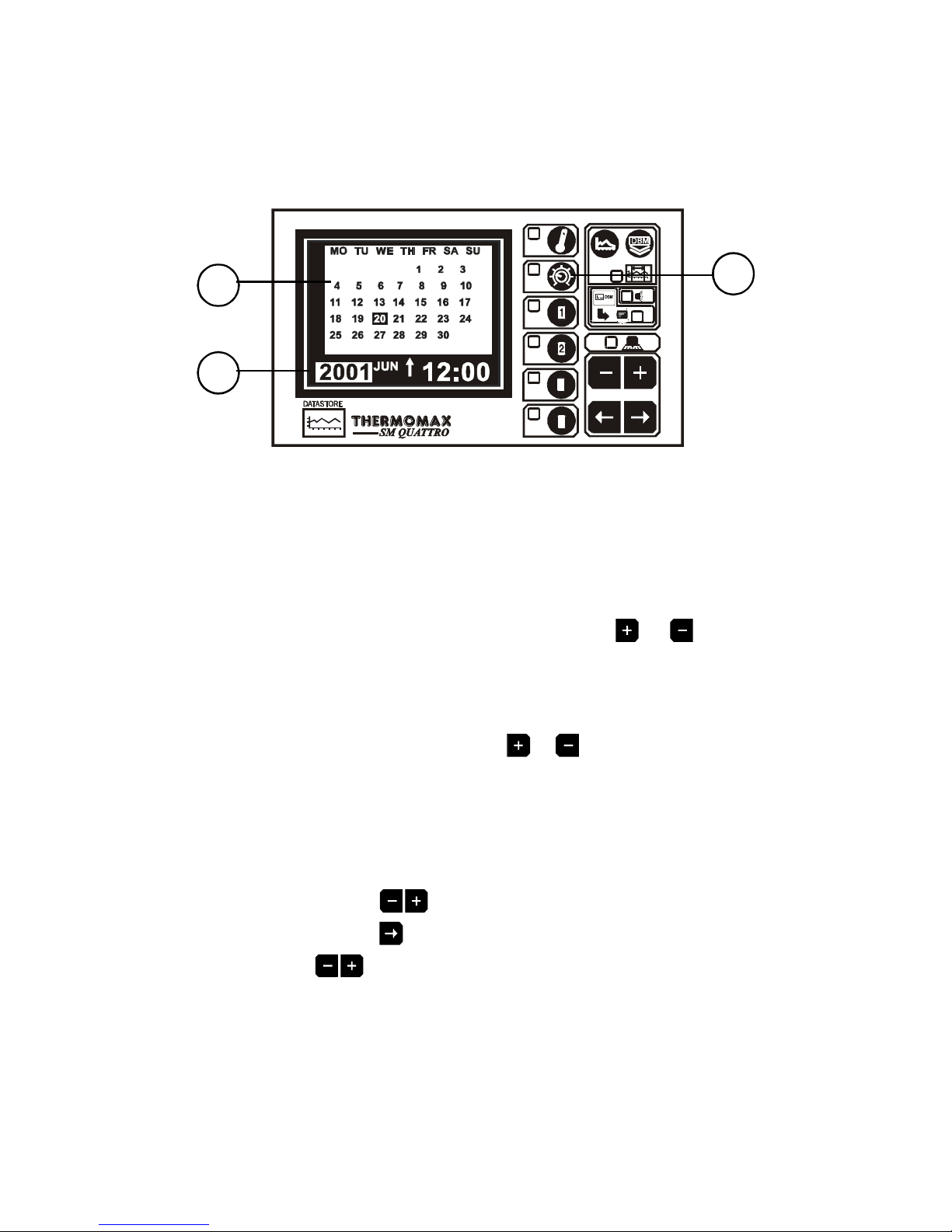
3.3.1 SET SCREEN 1 : CLOCK / CALENDAR
THERMOMAX
3
4
1 SET SCREEN function selector
The datalogging system uses the calendar to file the logged data.
2 Selection indicator
The highlighted parameter is adjusted by pressing the or key. .
(The selections are: ‘year’, ‘month’, ‘day’, ‘↑’, ‘hour’ and ‘minutes’.)
The ‘↑’ indicates that the day on the calendar above is being set.
The clock is in 24-hour format.
To advance quickly, press and hold the or key for auto repeat.
3 Calendar
This is the calendar of the month selected, with day of the week indication.
SETTING THE DATE AND TIME:
Step 1 : Use the keys to set the current ‘Year’.
Step 2: Use the key to move to the ‘Month’ option and then use the
keys to set the current month.
Step 3: Repeat step 2 to set the current ‘date’ and ‘time’ (‘minutes’
and ‘hours’) in turn.
2
3
1
 Loading...