

THERMOMAX
SM DUE
TWO CHANNEL DATALOGGER AND ALARM
ENGLISH
www.Thermomax-Group.com

CONTENTS
SECTION 1 - INTRODUCTION .............................................................................. 2
SECTION 2 - INSTALLATION ................................................................................ 3
2.1 - SM DUE Unit ......................…….................................................... 4
2.2 - Sensors .......................................................................................... 4
2.3 - Alarm Relay .................................................................................... 5
2.4 - Power Connections and Wiring Diagram ................................ 5
2.5 - Battery ............................................................................................. 5
SECTION 3 - OPERATION ................................................................................... 6
3.1 - DESCRIPTION ............................................................................. 6
3.2 - MAIN SCREENS:
3.2.1 MAIN SCREEN 1: Channel Temperature Display ...... 8
3.2.2 MAIN SCREEN 2: Current Day Plot Screen ............…. 9
3.3 - SET SCREENS:
3.3.1 SET SCREEN 1: Clock / Calendar …............................. 10
3.3.2 SET SCREEN 2: System Pre-sets 1............................... 11
3.3.3 SET SCREEN 3: System Pre-sets 2 …………....……. 13
3.4 - SYSTEM DIAGNOSTICS:
3.4.1 DATABANK DIAGNOSTICS SCREEN ........................... 14
3.4.2 CHANNEL DIAGNOSTICS SCREEN ............................ 15
3.4.3 CALIBRATION TRIMMING SCREEN ............................. 16
3.5 - CHANNEL SCREENS: /
3.5.1 CHANNEL DISPLAY SCREENS .................................... 17
3.5.2 CHANNEL SET SCREENS ............................................ 18
3.6 - PLOT HISTORY :
3.6.1 Data log of previous days ………………………............ 19
3.7 - DATA TRANSFER: ................................................................. 20
3.7.1 Transferring Data Using the Masterlink Software ..... 20
3.7.2 Transferring Data to the Masterlink Hardware ........... 20
3.7.3 Printing Data to the Thermomax Serial Printer ............ 22
3.8 - DATA TRANSFER - PANELMOUNT UNITS ONLY ........................ 23
SECTION 4 - FAULT FINDING .........................................................................…. 27
SECTION 5 - SPECIFICATIONS .......................................................................… 28
KEYPAD LOCK …………………………………………………………......……. 29
SM DUE PANELMOUNT ……………………………………........……………… 30
1

2
SECTION 1 INTRODUCTION
The SM DUE microprocessor-based datalogger uses the novel approach of a
paperless logging and filing system, which allows the data of any day in its history to
be read and examined with a few key presses.
The large graphics LCD display communicates the information to the user with
clarity, making programming and setting up friendly and uncomplicated, without
compromising its sophistication and digital accuracy.
SUMMARY OF FEATURES
DATALOGGER
• Paperless datalogger with automatic filing by date
• 50-year clock / calendar for datalogger filing.
• The temperature from each Channel is sampled every 5 minutes and stored
to an internal databank.
• ‘Percentage of internal databank used’ indication in bargraph and digital form.
• Once the databank is 100% full, the first eighth of the stored data will
automatically be replaced. (For the capacity of the databank, see Section 5).
• Power Supply options of either Mains or DC.
• Contents of internal databank can be transferred directly to the PC using the
MASTERLINK Software or via a MASTERLINK Hardware module to a PC at
a remote site.
ALARM
• 2-Stage high and low level alarms with mute and reset facilities,
• Stage 1 temperature threshold with trigger delay.
• Stage 2 limit temperature with immediate trigger.
• Diagnostics screen revealing system parameters.
• Alarm history record for low alarm, high alarm and power fail.
• Battery back-up for power-fail operation.
Note: The information supplied in this manual is for guidance only - no part of this
may be used for any agreement, whether express or implied, or to form any contract.

SECTION 2 INSTALLATION
Note: This installation procedure is for guidance only, and its suitability should be
verified by the installer.
SAFETY PRECAUTIONS
1. Before attempting to install and operate the unit, read this instruction manual
carefully.
2. Installation and any maintenance required should only be carried out by
suitably qualified personnel.
3. It is recommended that the unit be connected to the mains supply via a
suitably rated isolating switch.
4. WARNING: When the unit is connected to the mains supply and the
cover is opened, circuits at mains voltage will be exposed. Therefore
when installing the unit, ensure all required connections (including battery
connection, if included), are made and covers replaced before turning on the
mains supply. Ensure that all the connections made are secure. If any
maintenance work is required e.g. installing a new battery, ensure that the
unit is isolated from the mains supply before removing the cover. Never
leave the unit unattended if the cover has been removed and the mains
supply is connected.
5. Do not exceed unit ratings as shown on the ratings label.
6. It is advisable to route mains cables away from low voltage or sensor cables.
3

2.1 SM DUE UNIT
NOTE: For viewing comfort, the SM DUE unit should be positioned at eye
level. It is always good practice to keep electronic equipment away from
cold, heat and electrical plant, as extremes of temperature may reduce the
lifetime of the device, and heavy electrical loads, switches, relays or
contactors too close to the device may cause electrical and electro-magnetic
interference when switched on or off.
2.1.1 Knock out the entries into the moulding to be used for connection, either
behind or under the moulding, whichever is suitable for the particular
installation.
2 .2.2 Fasten the screw corresponding to the top centre lug on the back of the SM
DUE moulding, into the wall or panel on which the unit is to be mounted.
Leave a gap of approximately 3mm between the screw head and the wall.
Position the moulding and slot in the lug over the screw.
2.2.3 Level the SM DUE moulding and, if using rear entry, mark the entry holes in
the panel behind the appropriate knock-out entries, as well as the two lower
mounting holes.
Remove the moulding, drill the necessary holes in the panel, assemble any
grommets or conduit adapters if used, replace the moulding and fasten using
the two lower screws.
2.2 SENSORS
Temperature sensors, SXTM PT100 are used with all Thermomax units. They
are available in lengths from 5m to 100m, as are the sensor extenders, and
all come with a 4-way telephone plug. Each sensor comes with an original
Thermomax calibration certificate. The standard sensor can measure
temperatures from +50°C / -50°C.
Note: Using suitable 3-core or 4-core cable, the sensor can be extended,
according to the diagram shown below.
Note: In doing this, Thermomax calibration is removed.
The standard sensors PT100 are not suitable for use in acidic or alkaline
environments and should not be used in fluids.
Please note however, that as with all PT100 sensor applications, a good
connection is vital. It is therefore recommended that wherever there is any
doubt, a factory- extended sensor or sensor extender should be used.
4

2.3 ALARM RELAY
NOTE: The alarm relay is a 3 contact changeover arrangement that is
isolated (volt-free). This relay is normally energised, and switches off when
the alarm is triggered, or in the case of power failure. It may be used to
trigger an external bell, warning lamp, or digital communicator (telephone
dialler).
If an external device is used connect the alarm as appropriate, according to
the diagram in the next section.
2.4 POWER CONNECTIONS AND WIRING DIAGRAM
NOTE: This device should be properly earthed. Flexible wires simplify
connection to the terminals. All connections should be secure and adequately
tightened. It is good practice to keep mains cables away from sensor cables
and other low voltage signal cables.
Connect the supply to the unit, as per diagram below, using the appropriate
input voltage according to the application.
Alarm
Relay
L E N + -
Connect as appropriate
to application
Mains
Input
220 - 240V AC
DC
Input
20 - 28V DC
Sensors
CH1 CH2
SWITCH OPEN = DOOR OPEN
SWITCH CLOSED = DOOR CLOSED
Doo
r
max
5A
PC
2.5 BATTERY
The battery supplied is a 9V PP3 nickel metal hydride rechargeable battery
and is attached to the lid of the terminal compartment, but not plugged in.
This should be plugged in after installation. This battery is not essential for
the system operation, but is used in the case of power failure, thereby
continuing to log the two input temperatures for 6 - 7 hours, and maintaining
the system clock.
If the power cut takes longer and the battery is discharged, the clock must be
set when the power supply is re-established. The system parameters remain
intact.
It is recommended that the battery is changed every 12 months, in order to
maintain good power failure operation. When replacing, ensure that the type
of battery used is as specified - only a rechargeable PP3 battery should be
used directly, as the battery is charged from the unit.
5

6
SECTION 3 SM DUE OPERATION
In order to fully understand the operation of the SM DUE, this section should
be read carefully.
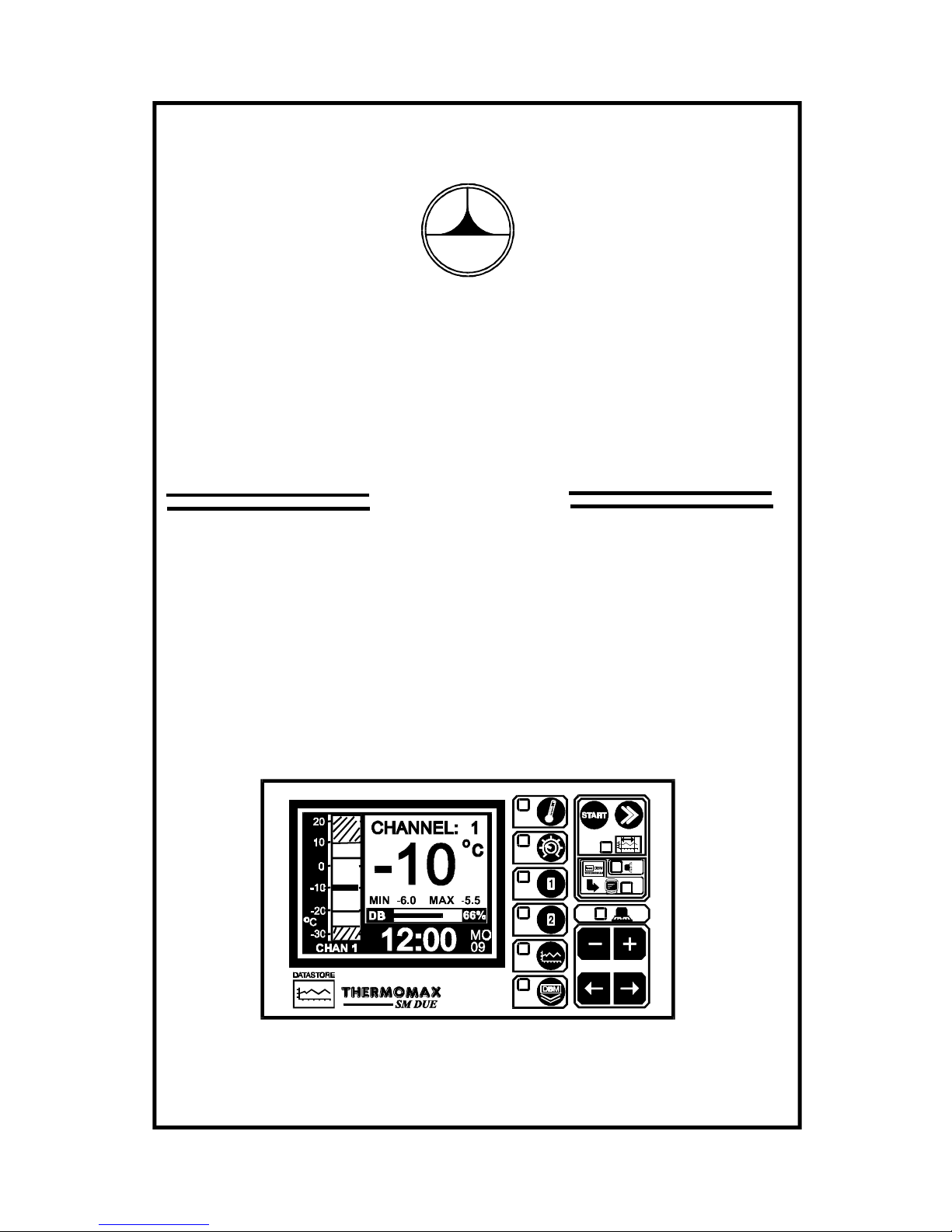
3.1 DESCRIPTION
SM DUE
°C
MIN -6.0 MAX -5.5
1 GRAPHICS LCD DISPLAY
Displays all the information. The contrast is adjustable to suit the user.
(See 3.2.1 Main Screen 1).
2 FUNCTION KEYS
There are six function keys on the SM DUE datalogger:
- Main Screen 1 - Channel 2 Display Screen
- Main Screen 2 - Channel 2 Set Screen
- Set Screen 1 - Plot History Screen
- Set Screen 2
- Channel 1 Display - Data Transfer Key
Screen
- Channel 1 Set Screen
3 SELECT KEYS
Within each function, there are some parameters that can be selected for
setting or displaying purposes. The keys allow the required
parameter to be chosen, without changing any of its properties.
5
4
3
2
1
4 SET KEYS
The and keys are used to set the value of any selected parameter, by
increasing and decreasing the value respectively. In most of the functions,
described later in the manual, the and keys have an auto-repeat
facility: press and hold the key in order to advance quickly.
Note: The and keys are the only keys which can alter the value of a
selected parameter. Other keys may be pressed to view or select these
parameters without effecting any change in the system.
5 INDICATORS
The System Alarm can be triggered by the high temperature alarm, low
temperature alarm, or by a sensor fault.
7
DATA TRANSFER IN PROGRESS
SYSTEM ALARM

8
3.2 MAIN SCREENS
3.2.1 MAIN SCREEN 1: CHANNEL TEMPERATURE DISPLAY
SM DUE
1 MAIN SCREEN function selector.
2 Two channel digital temperature display, viewed in either °C or °F.
3 High and Low Alarm Limits for each channel plus date of last alarm.
4 Maximum and minimum daily temperatures for each channel.
Note: The display contrast may be adjusted in this screen. Press to
increase and to decrease the contrast. To adjust quickly, press and hold
for auto-repeat.
2
3
5
14
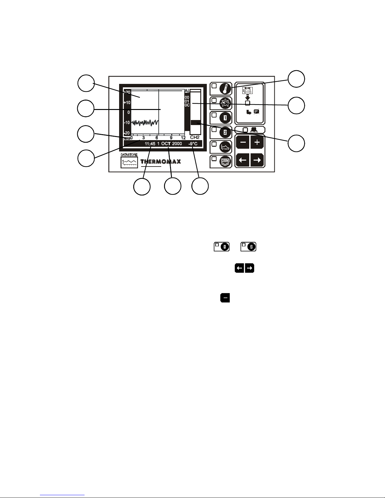
3.2.2 MAIN SCREEN 2: CURRENT DAY PLOT SCREEN
SM DUE
CHAN 1
1 MAIN SCREEN function selector
Pressing this key a second time displays the plot of the temperatures logged
for the current day. When this function has been selected, the current day
plot screen for either of the channels may be displayed by pressing the
appropriate channel function selector key: or .
2 Time of Day: This is the horizontal axis scale, and represents time. The
required twelve-hour period is selected using the keys.
3 Current Time-Bar: The time-bar indicates the current time of day, and
therefore the graph following this time bar will be blank. Samples from earlier
in the day may be examined by pressing the key to move the time-bar to
the left. The status of the current time bar is detailed at the bottom of the
screenas per 4-6 below.
4 Plot Time: This displays in digital form, the time indicated by the time-bar.
(The time is displayed in 5-minute sample intervals).
5 Plot Date: This shows the date of the currently displayed graph.
6 Time-Bar Temperature: This displays the logged temperature at the
time indicated by the time-bar. (The time / temperature is displayed in 5
minute sample intervals).
7 Alarm Log: Alarm indication to reveal the incidence of an alarm, the
time it occurred and its duration.
8 Unique electronic serial number of SM DUE.
9 ‘Other Channel’ Range: Display of max. and min. temperatures recorded.
10 This area of the display shows any occurrence of a cold room door
opening.
Note: The recorded temperature data is displayed graphically with a 10
minute sample interval.
9
1
8
9
65
4
7
3
2
10
10
3.3 SET SCREENS
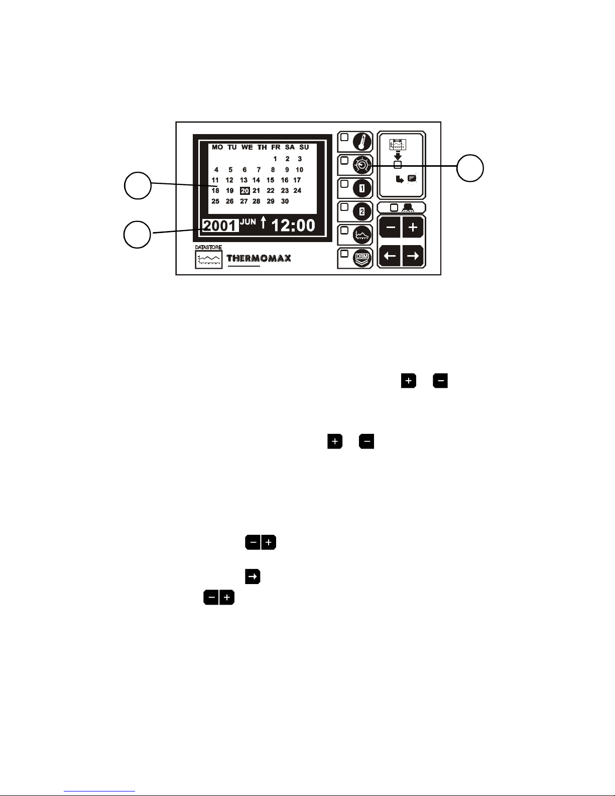
3.3.1 SET SCREEN 1: CLOCK/CALENDAR
SM DUE
1 SET SCREEN function selector
The datalogging system uses the calendar to file the logged data.
2 Selection indicator
The highlighted parameter is adjusted by pressing the or key..
(The selections are: ‘year’, ‘month’, ‘day’, ‘↑’, ‘hour’ and ‘minutes’.)
The ‘↑’ indicates that the day on the calendar above is being set.
The clock is in 24-hour format.
To advance quickly, press and hold the or key for auto repeat.
3 Calendar
This is the calendar of the month selected, with day of the week indication.
SETTING THE DATE AND TIME:
Step 1: Use the keys to set the current ‘Year’.
Step 2: Use the key to move to the ‘Month’ option and then use the
keys to set the current month.
Step 3: Repeat step 2 to set the current ‘date’ and ‘time’ (‘minutes’
and ‘hours’) in turn.
1
3
2

11
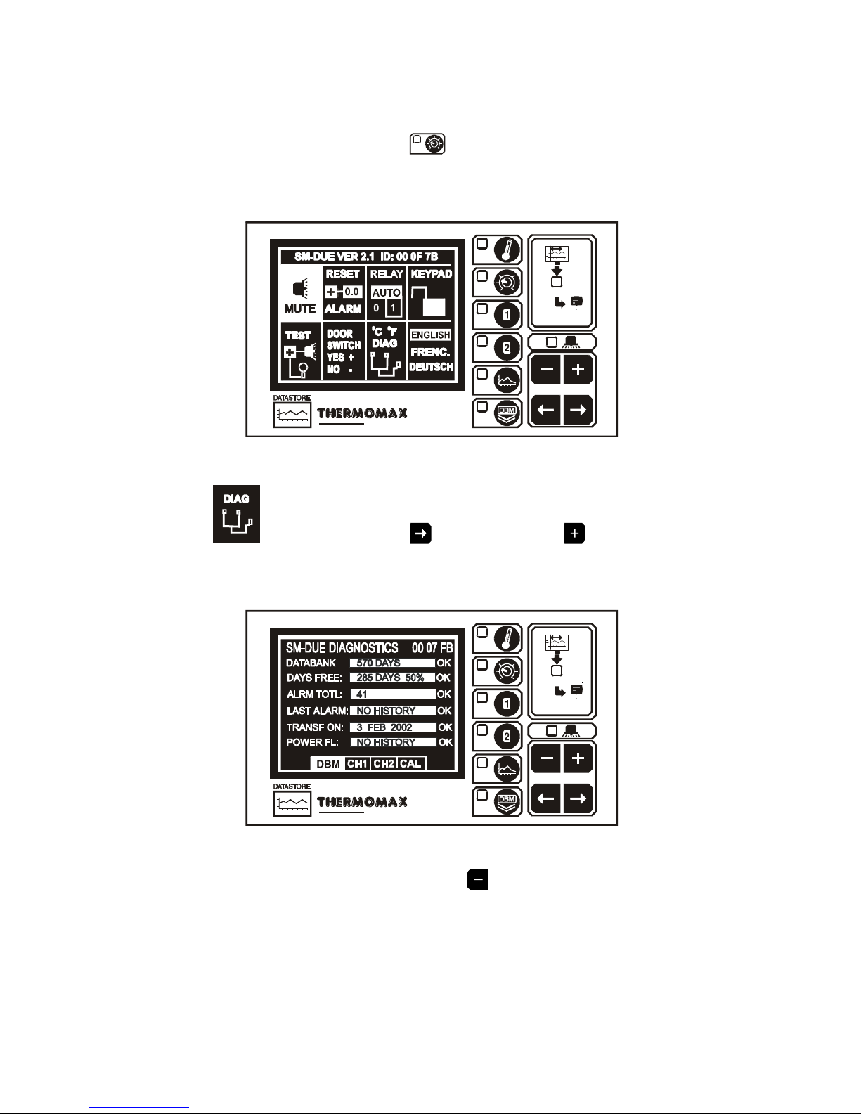
3.3.2 SET SCREEN 2: SYSTEM PRESETS
SM DUE
1 SET SCREEN function selector
Pressing this key a second time reveals Set Screen 2.
2 Alarm Mute
To mute the SM DUE’s internal audible alarm, press the key when the
MUTE window is selected. When the alarm system is reset, either manually
or by the temperatures dropping within pre-set limits, the alarm mute will be
cancelled automatically.
3 Alarm Reset
Any current activities, delays or counters are reset by pressing the key
when the RESET window is selected.
4 Alarm Relay Status
The output status of the alarm relay may be either viewed or altered by
pressing the or key when the RELAY window is selected.
0 = Relay Manually disabled (ALARM ON)
AUTO = For normal operation:
1 = Relay Manually activated (ALARM OFF)
5 Keypad Lock
Refer to page 26 of this manual.
1
7
6
3
2
5
4
10
9
8

12
6 Piezo and Indicator test
By pressing the key when the TEST window is selected, the SM DUE’ss
internal audible alarm will ‘sound’ and all indicators will illuminate.
This allows the user to ensure both are functional.
7 Door Switch Selection.
The SM DUE provides the option to connect a door switch for monitoring
purposes, the status of the door is displayed and logged in graphical form
(see section 3.2.2). This option may be enabled or disabled by pressing the
or key respectively. The diagram in section 2.4 shows how to connect
a door switch.
8 Temperature Scale.
The scale used by the system to communicate the temperature information
may be selected here. Press for °C and for °F..
9 Diagnostics.
By pressing the key when the DIAG window is selected, the SM DUE
DIAGNOSTICS screen is activated. (see next section 3.4).
10 Language Selection
The language used by the system to communicate the information may be
selected here. Choose the and keys to make your English, French or
German Language selection.

3.3.3 SET SCREEN 3: SYSTEM PRESETS 2
SM DUE
1 SET SCREEN function selector
Pressing this key a third time reveals Set Screen 3.
2 Alarm Mute Period for Channel 1 (from 0 to 95 minutes). If any key is
pressed during an Alarm situation for this channel, the buzzer will be muted
(silenced) for this period.
3 Alarm Mute Period for Channel 2 (from 0 to 95 minutes). Same as above.
4 Channel Select for Channel 1. Each sensor input can be “switched” on or off
by pressing the or keys for 5 seconds respectively. When the sensor
input is switched “ON”, the unit will operate in normal mode and the actual
sensor temperature will be monitored and logged to the databank every 5
minutes. If the sensor input is switched “OFF”, the unit will display 0°C
continuously. This value will also be logged to the databank. Hence it is
therefore only necessary to connect sensors to the required number of inputs.
NOTE:
If a channel is switched off, the alarm parameters will automatically revert
back to the default factory settings to prevent an alarm occurrence. These
parameters cannot be changed until the sensor input is switched on again.
5 Channel Select for Channel 2.
13
1
4
2
5
3
3.4 SYSTEM DIAGNOSTICS
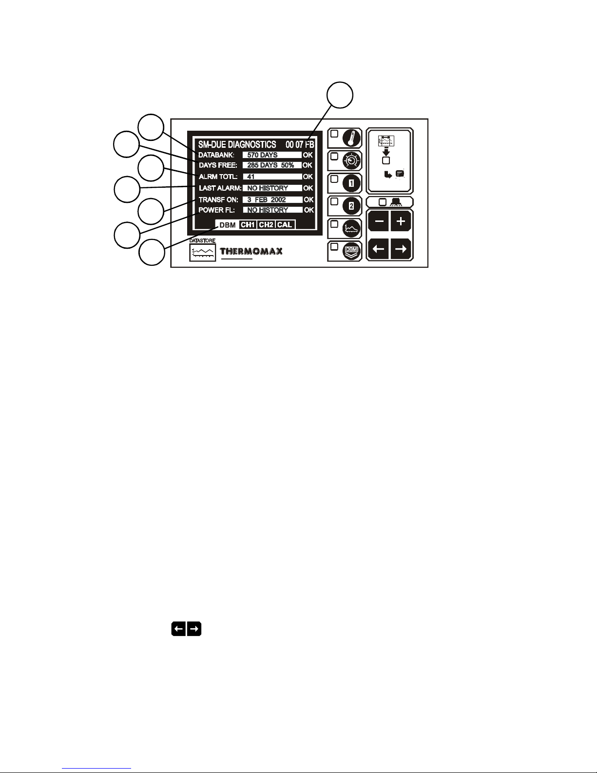
3.4.1 DATABANK DIAGNOSTICS SCREEN
SM DUE
1 This is the unique electronic signature of the SM DUE.
2 The DATABANK window shows the capacity of the internal databank. There
are two SM DUE options available:
(a) Recording frequency 5 minutes – Databank capacity 570 days
(approx. 1 ½ years - factory default)
(b) Recording frequency 10 minutes – Databank capacity 1128 days
(approx. 3 years)
3 The DAYS LEFT window shows the total number of days, and also the
total percentage of the databank, which have not yet been ‘used’.
4 The ALRM TOTL window shows the total number of alarm incidences
which have occurred in the current year.
5 The LAST ALRM window shows the last date on which an alarm condition
occurred.
6 The TRANSF ON window shows the date on which the contents of the
internal databank need to be transferred.
7 The POWER FL window shows the last date on which the power failed.
During a power fail situation this window will display the duration, in
minutes, of the power failure.
8 Diagnostics Screen Selection.
Use the keys to move between one of four diagnostic screens:
- DBM: Databank Diagnostics Screen (Ref. 3.4.1 above)
- CH1: Channel 1 Diagnostics Screen (Ref. 3.4.2)
- CH2: Channel 2 Diagnostics Screen (Ref. 3.4.2)
- CAL: Calibration Trimming Screen (Ref. 3.4.3)
2
3
4
5
6
7
8
14
1

15
3.4.2 CHANNEL DIAGNOSTICS SCREEN
SM DUE
1 The CHANNEL window shows the number of the currently selected
channel.
2 The INPUT TYPE window shows which type of sensor is being used.
(PT100 in this case).
3 The CALIB DATA window shows calibration values, for factory use only,
and the current temperature reading.
4 The LAST CALIB window shows the date when the SM DUE was
calibrated, (in this case 5 JAN 99).
5 The AL. HIGH window shows the date when the last high alarm condition
occurred for this channel.
6 The AL LOW window shows the date when the last low alarm condition
occurred for this channel.
1
2
3
4
5
6

16
3.4.3 CALIBRATION TRIMMING SCREEN
Calibration trimming allows qualified personnel to adjust the SM DUE’s
calibration by ± 2°C.
Note: A known reference temperature should be used.
SM DUE
CALIBRATION
PLEASE REFER TO MANUAL
To enter the CALIBRATION TRIMMING Screen, press and hold the key
for 5 seconds.
SM DUE
-11° -10°
CHAN 1
0
0
CHAN 2
Use the keys to move to the channel that requires calibration
trimming. Then use the or keys to adjust the current temperature
reading.
17
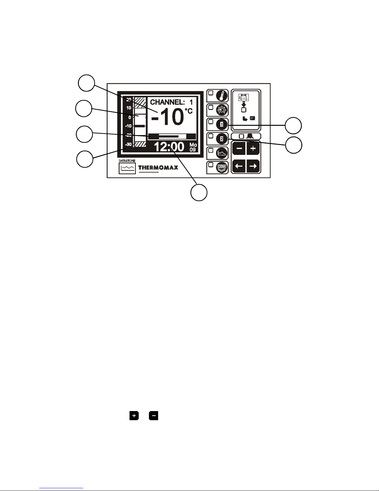
3.5 CHANNEL SCREENS
3.5.1 CHANNEL DISPLAY SCREENS
SM DUE
DB
66%
DOOR OPEN
°C
MIN -6.0 MAX -5.5
1 CHANNEL 1 function selector: displays the information for channel 1.
2 CHANNEL 2 function selector: displays the information for channel 2.
3 Clock display: 24-hour format with day of week abbreviation.
4 Temperature bargraph: High and low alarm limits are shown as shaded
areas. The two horizontal ‘lines’ represent the maximum and minimum, high
and low temperature alarms respectively.
5 Digital display of Channel temperature, with minimum / maximum indication.
The minimum and maximum values are daily values, and are reset at
midnight.
6 Internal databank indicator: This indicates the percentage ‘used’, in both
bargraph and digital form.
7 When the door switch facility is activated (see 3.3.2), this area will show the
status of the door as ‘door open’ or ‘door closed’. Note that if there is no
switch connected, the unit will display ‘door open’.
Note: The display contrast may also be adjusted from any of these screens
by pressing the or keys.
2
1
3
5
4
6
7

18
3.5.2 CHANNEL SET SCREENS
SM DUE
1 Channel 1 function selector
2 Channel 2 function selector
Pressing either of these keys a second time will display the “Channel Set
Screen” for the appropriate channel.
3 Bargraph Display Scale
By pressing the or key, the bargraph display scale may be adjusted to
show the temperature range best suited to the particular installation. This
scale is also used for the “Plot display” (Ref. 3.2.2 Current Day Plot and 3.6
Plot History).
4 High Alarm Stage 1 temperature (-50°C to +50°C)
The Stage 1 alarm is a time/temperature-related alarm. If the maximum
threshold is exceeded, a timer is initiated, and no further action is taken at
this time.
5 High Alarm Stage 1 Delay (1 - 99 min.)
After the maximum threshold has been exceeded (Ref. 4 above), the alarm
will not be triggered until the timer exceeds the time delay set here.
If the temperature drops below the threshold before the expiry of this delay,
the timer is reset. If following this the temperature rises above the threshold
again, the timer restarts from zero.
6 High Alarm Limit Stage 2 temperature (-50°C to +50°C)
If at any time this limit is exceeded the time delays will be overridden and the
alarm will trigger immediately.
7 Low Alarm
All the functions described in 4-6 above also apply to the low alarm.
1
2
65
4
3
7

19
3.6 PLOT HISTORY
3.6.1 DATA LOG OF PREVIOUS DAYS
SM DUE
AUG
1 Plot History function selector
When this key is pressed, the directory of the contents of the internal
databank is displayed, as above.
2 The highlighted months on this screen are the months for which the
databank contains data.
3 Current Selection
To view the plot of a particular day, select the required month from the
calendar using the keys, followed by the key to accept the
selection. A second screen appears for the selection of the day, after which
the logged data for the required day is displayed for inspection.
(Ref. Section 3.2.2 MAIN SCREEN 2: Current Day Plot Screen)
When the required plot is displayed, the plot screen for either of the channels
may be viewed by pressing the appropriate channel function key: or
.
To exit the Plot History function, press the main key .
1
2
3

20
3.7 DATA TRANSFER
The SM DUE is supplied with an internal reusable 1 ½ year databank. The
contents of this databank may be transferred directly to the PC using the
MASTERLINK Software or, alternatively, the MASTERLINK Hardware may be
used as an intermediate storage device to transfer data to a PC at a remote
location.
3.7.1 Transferring Data Using the Masterlink software
NOTE: Before data can be transferred to the PC, the software must be set
up on the PC, as per the MASTERLINK Software Manual.
(a) Plug the 8 Way SX plug of the ‘PC Cable Assembly’ into the
SERIAL LINK of the SM DUE.
(b) Then plug the 9 Way ‘female D type’ connector into any free serial
port in the PC.
NOTE: For Panelmount units, read section 3.8 before attempting to
download or print data.
3.7.2 Transferring Data to the Masterlink Hardware
(a) Connect the ‘MASTERLINK Cable Assembly’, from the SERIAL LINK SX
socket of the SM DUE to the MASTERLINK Hardware.
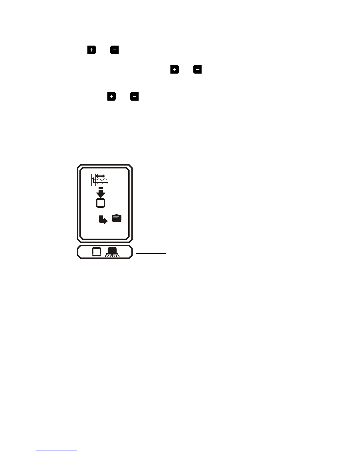
(b) Press the key to reveal the following screen:
SM DUE
DATA TRANSFER
MASTERLINK
PRINTER
CANCEL
(c) To download data to the Masterlink Hardware unit, (Part No. C0321), press
the key and the following screen will appear:

21
SM DUE
TRANSFER 0001 DAYS
INCREASE
DECREASE
CONFIRM
(MAX: 61 DAYS)
(d) The user can now choose any number of days, (starting from the current
day), to transfer to the Masterlink Hardware – from 1 day up to the total
number of days stored in the internal databank of the Thermomax unit. In
this example, there are 61 days of data stored in the Databank.
(e) To increase or decrease the number of days to download, press the or
key and then press the key to confirm this. The maximum number of
days the user will be able to download, corresponds to the number of days
data stored in the databank.

22
3.7.3 Printing Data to the Thermomax Serial Printer
(a) Press the key to reveal the following screen:
SM DUE
DATA TRANSFER
MASTERLINK
PRINTER
CANCEL
(b) To print data directly to the serial printer, (Part No. A6747), press the key and
the following screen will appear:
SM DUE
PRINT 0002 DAYS
(MAX: 91 DAYS)
INCREASE
DECREASE
CONFIRM
(c) The user can now choose any number of days, (starting from the current
day), to print directly to the Thermomax serial Printer – from 1 day up to the
total number of days stored in the internal databank of the Thermomax unit.
In this example, there are 61 days of data stored in the Databank.
(d) To increase or decrease the number of days to print, press the or key
and then press the key to confirm this.

3.8 DATA TRANSFER - PANELMOUNT UNITS ONLY
The following functions / features have been added to the new Panelmount units.
Mode 1 In Standard Mode the serial socket can be used for the following
functions:
• Direct connection to PC
• Direct connection to Masterlink Hardware
• Direct connection to Thermomax Serial Printer
The unit is despatched from Thermomax in this mode.
Thermomax Serial
Printer - A6747
Masterlink Hardware
Unit - C0321
PC
Mode 2 This mode is used to network up to 32 units to one PC, (see
illustration below).
SM QUATTRO
PANELMOUNT - C0445
SM DUE
PANELMOUNT - C0447
NETWORK CABLE
1m - A7004
10m - A7426
20m - A7427
50m - A7428
100m - A7429
200m - A7431
NETWORK
TERMINATOR - A7256
NETWORK
TERMINATOR - A7256
MASTERLINK SOFTWARE - C0322
(5m CABLE ASSEMBLY + DISK)
MASTERLINK EXTENSION KIT : 10m - A7030
OR
MASTERLINK EXTENSION KIT : 20m - A7378
OR
MASTERLINK EXTENSION KIT : 40m - A7342
OR
MASTERLINK EXTENSION KIT : 60m - A7100
NETWORK
SOCKETS
SMX 100
PANELMOUNT - C0444
23

MODE 1 – STANDARD MODE (DISABLING NETWORK MODE)
If the network is enabled and the user tries to download data to the Masterlink
Hardware or print directly to the Thermomax Serial Printer, the following screen will
appear.
SM DUE
DATA TRANSFER
FUNCTION
NOT AVAILABLE
PLEASE REFER TO MANUAL
In order to download data to the Masterlink Hardware unit or print directly to a
Thermomax Serial Printer, the network must be disabled.
To disable network, press the key twice to reveal the following screen:
SM DUE
Select the window by using the key and press the key to show the
following screen:
24
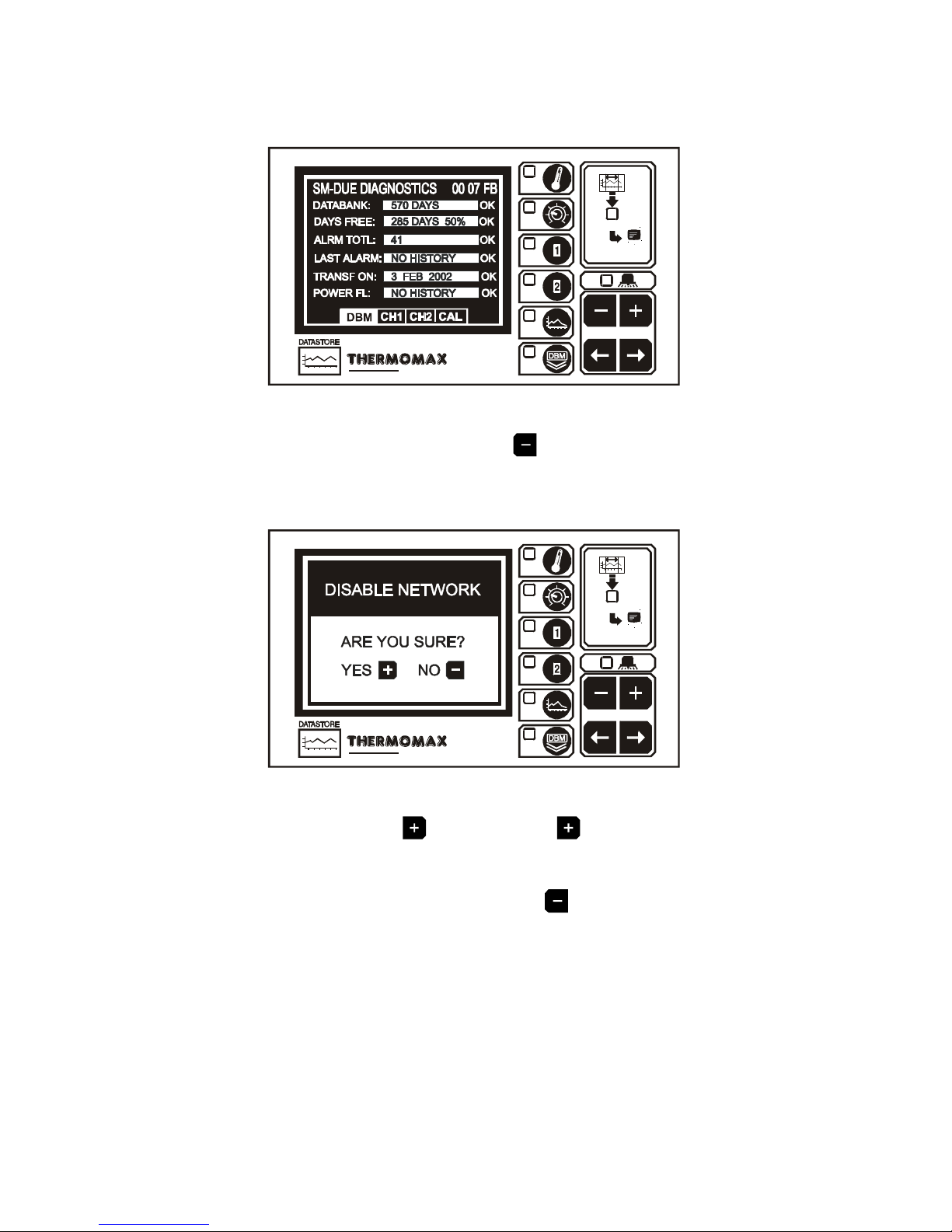
SM DUE
With this screen displayed, press and hold the key for approximately 10
seconds. The following screen will appear:
SM DUE
To disable the network press the key. (When the key is pressed, the SM Due
will switch off and back on again).
If you do not wish to disable the network, press the key..
25
MODE 2 – NETWORK MODE (SELECTING NETWORK MODE)
To select the network mode, press the key twice to reveal the following
screen:
SM DUE
Select the window by using the key and press the key to show the
following screen:
SM DUE
With this screen displayed, press and hold the key for approximately 10
seconds. The following screen will appear:
26

SM DUE
To enable the network press the key. (When the key is pressed, the SM Due
will switch off and back on again).
If you do not wish to enable the network, press the key..
SECTION 4 FAULT FINDING
Problem: Nothing happens when the unit is powered-up.
Cause / Remedy: One of the fuses could be blown - check and replace if
necessary (refer to specifications for values). If the fuses blow
again, contact the agent where the unit was purchased.
Problem: The temperature display is fluctuating.
Cause / Remedy: One of the sensor connections may be loose, or a sensor
cable may be too close to a mains cable. Tighten connections
and re-route cables if necessary.
Problem: Unable to set any of the parameters: Keypad will not operate.
Cause / Remedy: The Keypad Lock is on - See ‘Keypad Lock’.
Problem: The display screen is too dark or too faint.
Cause / Remedy: Adjust the display contrast to suit - See ‘Display Contrast’ in
the MAIN SCREEN 1 section.
Problem: The System Alarm light is flashing once every 3 seconds.
Cause / Remedy: This indicates a system warning. Check the ‘CHANNEL
DIAGNOSTICS’ screens for indication of the specific warning.
Problem: The System Alarm light is flashing and the audible sounder is
active.
Cause / Remedy: This indicates a system fault or temperature alarm. Check
the ‘CHANNEL DIAGNOSTICS’ screens for indication of the
specific alarm (Page 14).
27

SECTION5 SPECIFICATIONS
ELECTRICAL:
Supply Voltage: 220-240V AC Single Phase / 24V DC or
12V DC
Ambient Temperature: 0°C to +40°C
Fuses: 2 X 1A 20mm Quick Blow
Alarm Relay Output: 5A changeover 3 pin isolated - (volt-free
contacts)
May be used for low or mains voltage
MECHANICAL:
Dimensions: width: 165mm
height: 160mm
depth: 75mm
weight: SM DUE Unit: 0.96Kg
Sensor: (each) 0.13Kg
Box Material: Plastic
Front Panel: Reverse printed
Display: Large LCD supertwist graphics
SENSORS:
Type: SXTM PT 100 Platinum Film
Compensation: 3 wire compensated
Battery: 9V PP3 Rechargeable
DATABANK CAPACITY:
Recording Frequency of 5 minutes 570 days
Recording Frequency of 10 minutes 1128 days
PARTS LIST
SM DUE Unit (24V) C0403
SM DUE Unit (12V) C0419
Sensor (5m cable) A6905
Sensor (15m cable) A6915
Sensor (25m cable) A6925
Sensor (50m cable) A6950
Sensor (100m cable ) A7999
ACCESSORIES
Sensor Extender 10m A6911 Serial Printer A6747
Sensor Extender 20m A6921 Serial Printer Cable A7433
Sensor Extender 50m A6951 Network Terminators A7256
MASTERLINK Software C0322
MASTERLINK Hardware C0321
Network Connecting Cable : 1m (Ivory) A7004
Network Connecting Cable : 10m (Ivory) A7426
Network Connecting Cable : 20m (Ivory) A7427
Network Connecting Cable : 50m (Ivory) A7428
Network Connecting Cable : 100m (Ivory) A7429
Network Connecting Cable : 200m (Ivory) A7431
Masterlink Software Extension Kit : 10m (Ivory) A7030
Masterlink Software Extension Kit : 20m (Ivory) A7378
Masterlink Software Extension Kit : 40m (Ivory) A7342
Masterlink Software Extension Kit : 60m (Ivory) A7100
28

29
KEYPAD LOCK
The keypad may be locked or unlocked when this window is selected.
To lock, press the key and hold for 5 seconds.
To unlock, press the key and hold for 5 seconds.
When the keypad is locked, the SM DUE enters into a security mode, which renders
the unit ‘tamper-proof’.
There are three functions for which the set keys ( / ) will operate when the
keypad is locked.
(a) Display contrast (see 3.2.1 MAIN SCREEN 1);
(b) Alarm mute and reset (see 3.3.2 System Pre-sets);
(c) Entering the Diagnostics Screen for viewing (see section 3.4).
CE
This product has been tested to the EU EMC 89/336/EEC directive according to the
Manufacturer’s report, which is available on request.
This product is in conformance with the Low Voltage Directive 73/23/EEC.
Thermomax certifies that this datalogging and / or control device has been
manufactured to an ISO 9002 Quality System.
Thermomax undertakes to repair or replace the device if same is shown to be
defective in its manufacture and / or components, but Thermomax shall not be
responsible for any other financial or economic loss (or any indirect loss) which may
be incurred by the buyer / customer or others in the use of the device.
Any claim for repair or replacement must be made not later than 15 months after the
date of manufacture.
30
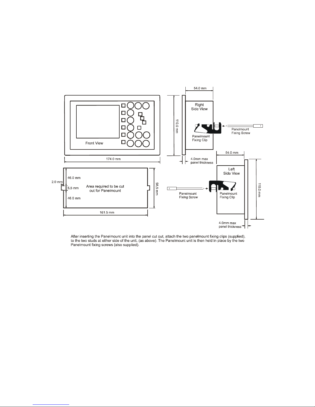
SM DUE PANELMOUNT
DIMENSIONAL DETAILS

31
WIRING DIAGRAM
Alarm Relay
max 5A
220 / 240 VAC
50Hz
Transformer 12V
THERMOMAX
PANEL-MOUNT
NOTE:
For SM DUE applications:
CH1 = CH1
CH2 = CH2
L
N
E
 Loading...