

Thermolec B-6U-FFB, B-10U-FFB, B-12U-FFB, B-15U-FFB, B-18U-FFB Installation Instructions Manual
...Page 1
THERMOLEC
Installation
Instructions
for
Electric
Boilers (USA)
DECEMBER 2010
VERSION 11
Page 2
.
.
5/18/2008
s
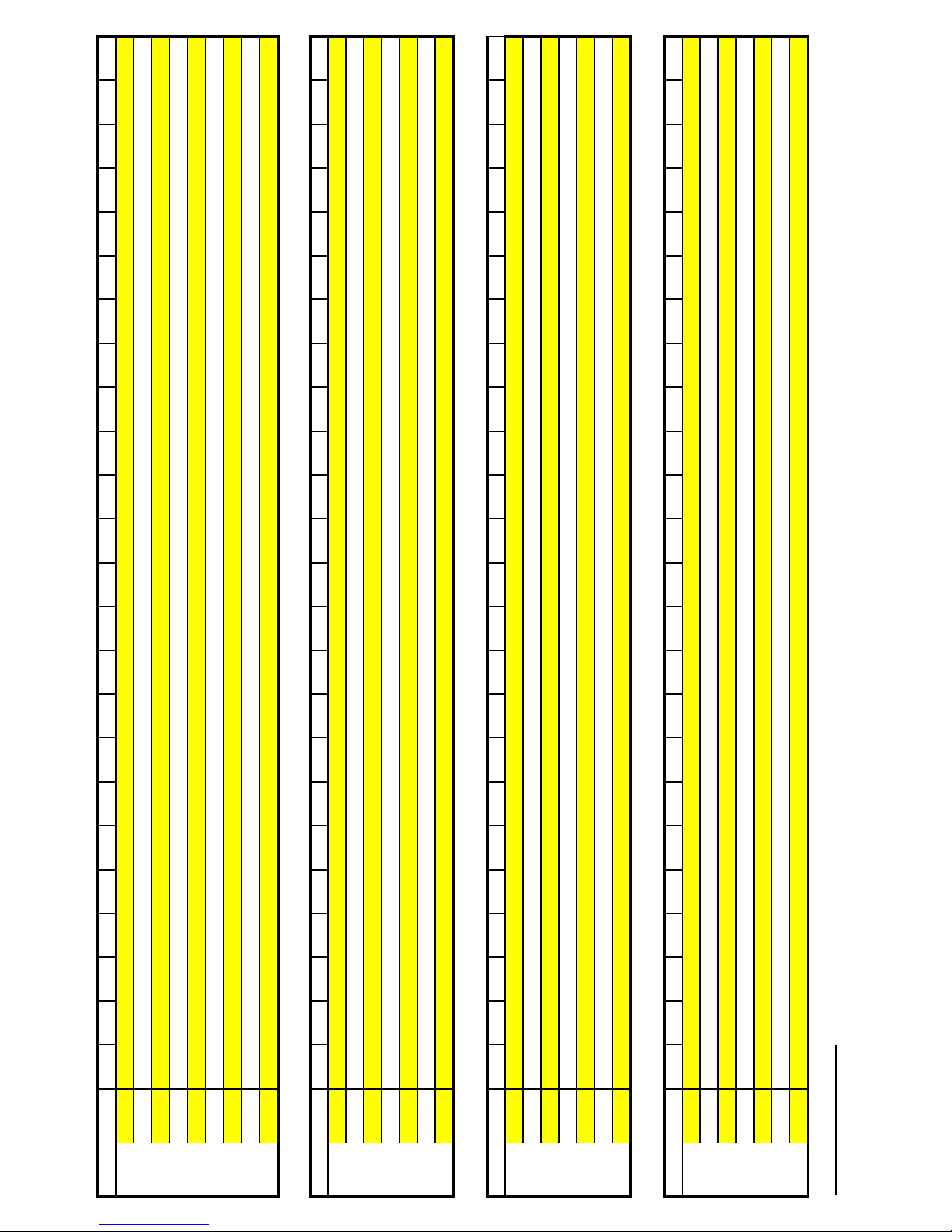
CostPerMillionBtu
0.038 0.040 0.042 0.044 0.046 0.048 0.050 0.052 0.054 0.056 0.058 0.060 0.062 0.064 0.066 0.068 0.070 0.072 0.074 0.076 0.078 0.080 0.090 0.100
100% 11.14 11.72 12.31 12.90 13.48 14.07 14.65 15.24 15.83 16.41 17.00 17.58 18.17 18.76 19.34 19.93 20.52 21.10 21.69 22.27 22.86 23.45 26.38 29.31
150% 7.42 7.82 8.21 8.60 8.99 9.38 9.77 10.16 10.55 10.94 11.33 11.72 12.11 12.50 12.90 13.29 13.68 14.07 14.46 14.85 15.24 15.63 17.58 19.54
200% 5.57 5.86 6.15 6.45 6.74 7.03 7.33 7.62 7.91 8.21 8.50 8.79 9.09 9.38 9.67 9.96 10.26 10.55 10.84 11.14 11.43 11.72 13.19 14.65
$/kWh
250% 4.45 4.69 4.92 5.16 5.39 5.63 5.86 6.10 6.33 6.57 6.80 7.03 7.27 7.50 7.74 7.97 8.21 8.44 8.68 8.91 9.14 9.38 10.55 11.72
Electricity 3412BTU/kWh
275% 4.05 4.26 4.48 4.69 4.90 5.12 5.33 5.54 5.76 5.97 6.18 6.39 6.61 6.82 7.03 7.25 7.46 7.67 7.89 8.10 8.31 8.53 9.59 10.66
300% 3.71 3.91 4.10 4.30 4.49 4.69 4.88 5.08 5.28 5.47 5.67 5.86 6.06 6.25 6.45 6.64 6.84 7.03 7.23 7.42 7.62 7.82 8.79 9.77
325% 3.43 3.61 3.79 3.97 4.15 4.33 4.51 4.69 4.87 5.05 5.23 5.41 5.59 5.77 5.95 6.13 6.31 6.49 6.67 6.85 7.03 7.21 8.12 9.02
(C.O.P.orEF)
SystemEfficiency
350% 3.18 3.35 3.52 3.68 3.85 4.02 4.19 4.35 4.52 4.69 4.86 5.02 5.19 5.36 5.53 5.69 5.86 6.03 6.20 6.36 6.53 6.70 7.54 8.37
400% 2.78 2.93 3.08 3.22 3.37 3.52 3.66 3.81 3.96 4.10 4.25 4.40 4.54 4.69 4.84 4.98 5.13 5.28 5.42 5.57 5.72 5.86 6.59 7.33
0.90 0.95 1.00 1.05 1.10 1.15 1.20 1.25 1.30 1.35 1.40 1.45 1.50 1.55 1.60 1.65 1.70 1.75 1.80 1.85 1.90 1.95 2.00 2.05
75% 12.00 12.67 13.33 14.00 14.67 15.33 16.00 16.67 17.33 18.00 18.67 19.33 20.00 20.67 21.33 22.00 22.67 23.33 24.00 24.67 25.33 26.00 26.67 27.33
80% 11.25 11.88 12.50 13.13 13.75 14.38 15.00 15.63 16.25 16.88 17.50 18.13 18.75 19.38 20.00 20.63 21.25 21.88 22.50 23.13 23.75 24.38 25.00 25.63
82% 10.98 11.59 12.20 12.80 13.41 14.02 14.63 15.24 15.85 16.46 17.07 17.68 18.29 18.90 19.51 20.12 20.73 21.34 21.95 22.56 23.17 23.78 24.39 25.00
85% 10.59 11.18 11.76 12.35 12.94 13.53 14.12 14.71 15.29 15.88 16.47 17.06 17.65 18.24 18.82 19.41 20.00 20.59 21.18 21.76 22.35 22.94 23.53 24.12
$/ccf
90% 10.00 10.56 11.11 11.67 12.22 12.78 13.33 13.89 14.44 15.00 15.56 16.11 16.67 17.22 17.78 18.33 18.89 19.44 20.00 20.56 21.11 21.67 22.22 22.78
NaturalGas 100,000BTU/therm
92% 9.78 10.33 10.87 11.41 11.96 12.50 13.04 13.59 14.13 14.67 15.22 15.76 16.30 16.85 17.39 17.93 18.48 19.02 19.57 20.11 20.65 21.20 21.74 22.28
95% 9.47 10.00 10.53 11.05 11.58 12.11 12.63 13.16 13.68 14.21 14.74 15.26 15.79 16.32 16.84 17.37 17.89 18.42 18.95 19.47 20.00 20.53 21.05 21.58
SystemEffciency
1.00 1.10 1.20 1.30 1.40 1.50 1.60 1.70 1.80 1.90 2.00 2.10 2.20 2.30 2.40 2.50 2.60 2.70 2.80 2.90 2.95 3.00 3.05 3.10
75% 13.96 15.36 16.75 18.15 19.55 20.94 22.34 23.73 25.13 26.53 27.92 29.32 30.72 32.11 33.51 34.90 36.30 37.70 39.09 40.49 41.19 41.88 42.58 43.28
80% 13.09 14.40 15.71 17.02 18.32 19.63 20.94 22.25 23.56 24.87 26.18 27.49 28.80 30.10 31.41 32.72 34.03 35.34 36.65 37.96 38.61 39.27 39.92 40.58
82% 12.77 14.05 15.32 16.60 17.88 19.15 20.43 21.71 22.99 24.26 25.54 26.82 28.09 29.37 30.65 31.92 33.20 34.48 35.76 37.03 37.67 38.31 38.95 39.59
85% 12.32 13.55 14.78 16.01 17.25 18.48 19.71 20.94 22.17 23.41 24.64 25.87 27.10 28.33 29.57 30.80 32.03 33.26 34.49 35.73 36.34 36.96 37.57 38.19
$/gal
90% 11.63 12.80 13.96 15.13 16.29 17.45 18.62 19.78 20.94 22.11 23.27 24.43 25.60 26.76 27.92 29.09 30.25 31.41 32.58 33.74 34.32 34.90 35.49 36.07
Propane 95,500BTU/gallon
92% 11.38 12.52 13.66 14.80 15.93 17.07 18.21 19.35 20.49 21.63 22.76 23.90 25.04 26.18 27.32 28.45 29.59 30.73 31.87 33.01 33.58 34.15 34.71 35.28
138,900BTU/galllon
3.20 3.25 3.30 3.35 3.40 3.45 3.50 3.55 3.60 3.65 3.70 3.80 3.90 4.00 4.10 4.20 4.30 4.40 4.50 4.60 4.70 4.80 4.90 5.00
95% 11.02 12.12 13.23 14.33 15.43 16.53 17.64 18.74 19.84 20.94 22.04 23.15 24.25 25.35 26.45 27.56 28.66 29.76 30.86 31.96 32.52 33.07 33.62 34.17
SystemEffciency
$/gal
FuelOil
75% 30.72 31.20 31.68 32.16 32.64 33.12 33.60 34.08 34.56 35.04 35.52 36.48 37.44 38.40 39.36 40.32 41.28 42.24 43.20 44.16 45.12 46.08 47.04 48.00
80% 28.80 29.25 29.70 30.15 30.60 31.05 31.50 31.95 32.40 32.85 33.30 34.20 35.10 36.00 36.90 37.80 38.70 39.60 40.50 41.40 42.30 43.20 44.10 45.00
82% 28.10 28.53 28.97 29.41 29.85 30.29 30.73 31.17 31.61 32.05 32.49 33.36 34.24 35.12 36.00 36.88 37.75 38.63 39.51 40.39 41.26 42.14 43.02 43.90
85% 27.10 27.53 27.95 28.37 28.80 29.22 29.64 30.07 30.49 30.92 31.34 32.19 33.03 33.88 34.73 35.57 36.42 37.27 38.11 38.96 39.81 40.66 41.50 42.35
90% 25.60 26.00 26.40 26.80 27.20 27.60 28.00 28.40 28.80 29.20 29.60 30.40 31.20 32.00 32.80 33.60 34.40 35.20 36.00 36.80 37.60 38.40 39.20 40.00
92% 25.04 25.43 25.82 26.22 26.61 27.00 27.39 27.78 28.17 28.56 28.95 29.74 30.52 31.30 32.08 32.87 33.65 34.43 35.21 36.00 36.78 37.56 38.34 39.13
95% 24.25 24.63 25.01 25.39 25.77 26.15 26.52 26.90 27.28 27.66 28.04 28.80 29.56 30.31 31.07 31.83 32.59 33.34 34.10 34.86 35.62 36.38 37.13 37.89
SystemEffciency
CoefficientofPerformance(C.O.P.)Thesameastheefficiencystatedasaratioofworkorusefulenergyoutputofasystemvs.theamountofenergyinputtedintothesystem
EnergyFactor(EF)Theefficiencyormeasureofoverallefficiencyofavarietyofappliances.WaterheaterefficienciesareratedbyEF
AnnualFuelUtilitizationEfficiency(AFUE)Themeasureofannualefficiencyofaresidentialheatingfurnaceorboiler.Accountsforoperationenergylossesoftheheatingunit
EnergyEfficiencyTerm
Page 3

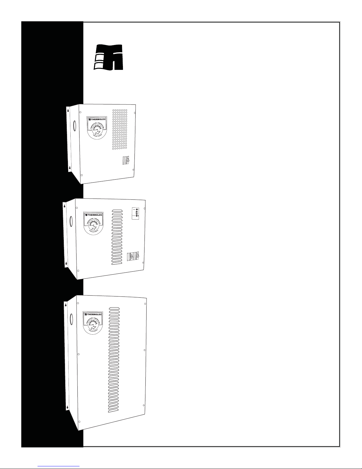
1 Components
Incoloy elements Manual reset
Electronic
temperature
sensor
thermal cut-out
Solid state relays
Mounting holes
Outlet 1-1/4ÊÊ NPT
Temperature /
pressure
gauge
Pump relay
Inlet 1-1/4ÊÊ NPT
Fig. 1
18”
Pump relay terminals
(dry contacts 10A)
Fuse and
fuse holder
Note : The model shown above is a typical FFB boiler 15kW / 240 Volts / 1 phase.
Model shown below is a TMB boiler 11kW / 240 / 1 phase.
Magnetic back-up contactor
Boiler control
transformer
18”
Circuit breaker
9”
Ground lug
Outdoor reset sensor
Fig. 3
18”
9”
13”
Page 1
Page 4
A
A
A
A
(
)
A30A60A60A60A
(U.S.A.)
(U.S.A.)
Wire Size 12 10 8 6 4 3 2 1 0 00 000
Amps @ 75°C (167°F)
20 30 45 65 85 100 115 130 150 175 200
Amps @ 90°C (194°F)
20 30 45 65 85 105 120 140 155 185 210
Notes :
Cable Amps Capacity vs Wire Size
1- This table should be used as a guide only. Always select the wire size according to the local
Electrical Code.
2- Always use wire suitable for 75°C (167°F) minimum, 300V or 600V as required.
3- All models with suffix "U" over 12 kW at 240V / 1ph require two feeders. Divide the Total
Amps by 2 to select the proper wire size.
4- COPPER WIRE ONLY.
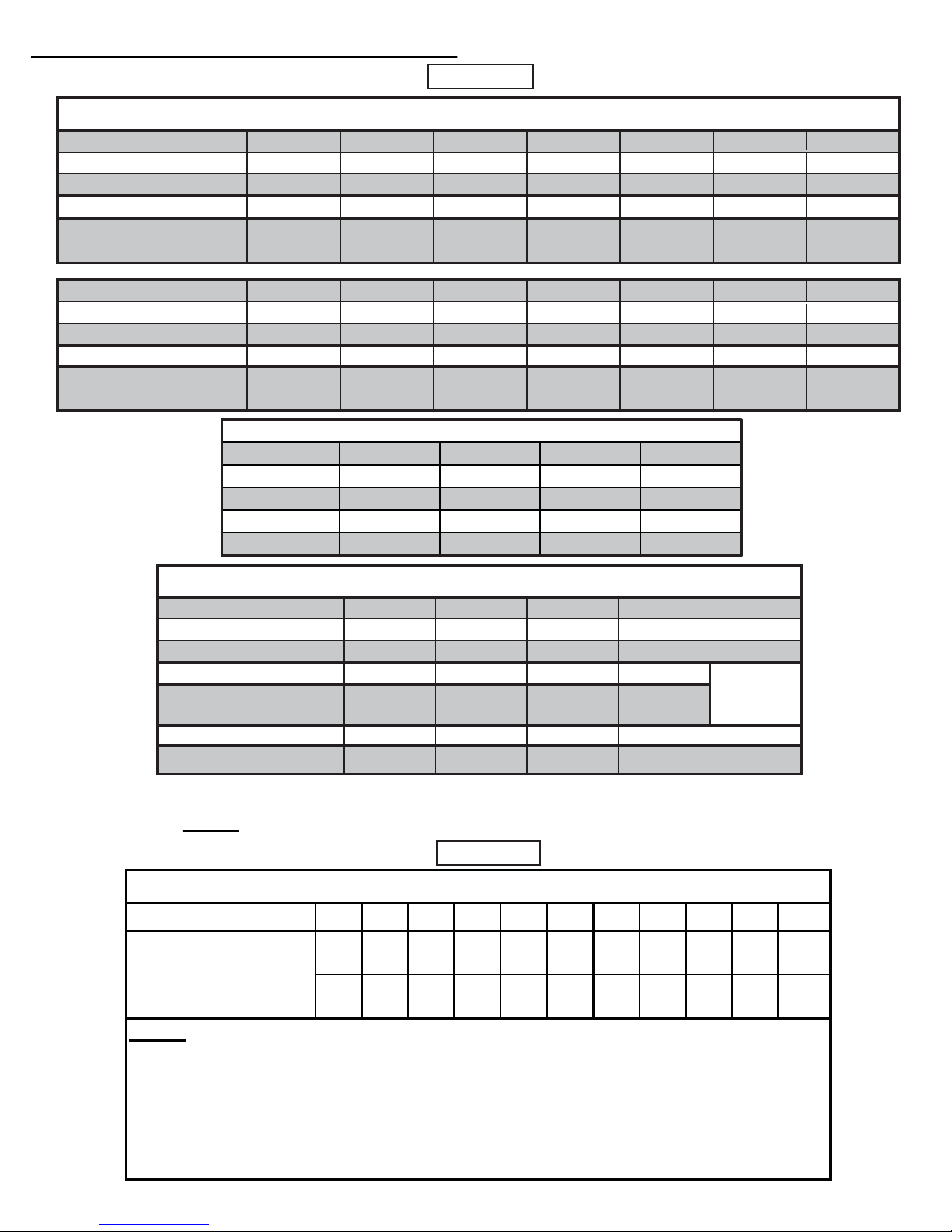
2 Standard specifications for all models
Mono Models B-3T MBU B-6TMBU B-9TMBU B-11TMBU
kW 36911
BTU/H 10,236 20,472 30,708 37,532
Total Amps 12.5 25.0 37.5 45.8
Breaker size 1 x 20A 1 x 40A 1 x 50A 1 x 60A
TMB MONO Model Specifications @ 240V / 1ph (U.S.A.)
Table 2
Standard Models Specifications @ 240V / 1ph
Dual-Energy Models B-5U-FFB B-6U-FFB B-8U-FFB B-9U-FFB B-10U-FFB B-12U-FFB B-15U-FFB
kW
BTU / H
Total Amps 20.83 23.96 33.33 37.50 41.67 47.92 62.50
No. Of Power Supplies 1 x 30A 1 x 30A 1 x 50A 1 x 50A 1 x 60A 1 x 60A 1 x 60A
(Breaker Size) 1 x 30A
Dual-Energy Models B-18U-FFB B-20U-FFB B-23U-FFB B-27U-FFB B-30U-FFB B-35U-FFB B-40U-FFB
kW
BTU / H
Total Amps 75.00 83.37 95.83 112.50 125.00 145.83 166.67
No. Of Power Supplies 1 x 60A 2 x 60A 2 x 60A 2 x 50A 3 x 60A 4 x 50A 4 x 60A
5 89105.75 11.5 15
17,060 19,619 27,296 30,708 34,120 39,238 51,180
18 20 23 27 30 35 40
61,416 68,242 78,479 92,128 102,360 119,420 136,480
A06 x 1A05 x 1)eziS rekaerB(
No. Of Power Supplies 1 x 60
NOTE: Other models, voltages and capacities available upon request. Please contact the factory.
Please use Table 3 below to select the wire size for the power supply.
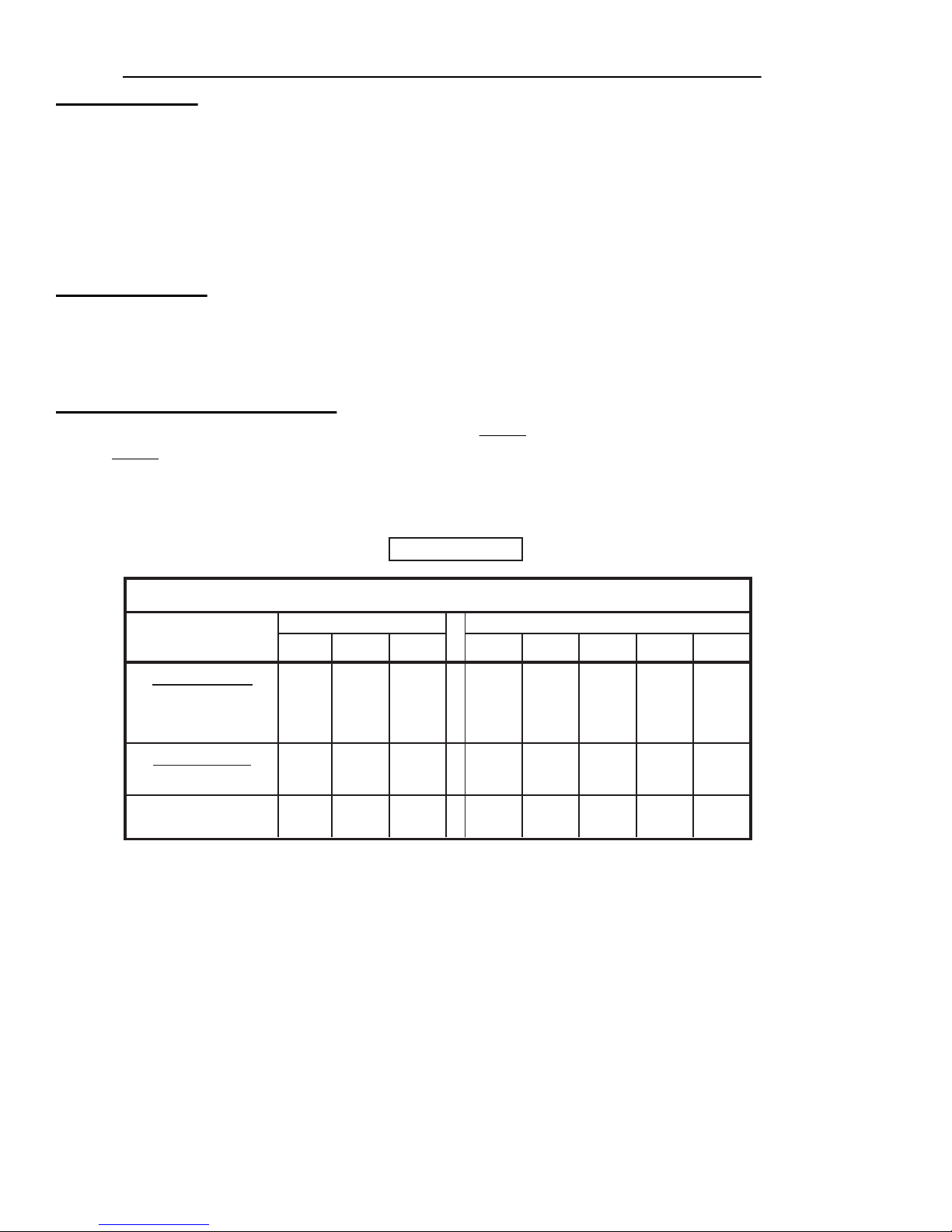
Standard Model Specifications @ 3ph
Dual-Energy Models B-18U-FFB B-24U-FFB B-30U-FFB B-35U-FFB B-40U-FFB
kW
BTU / H
Amps @ 208V / 3ph 48.00 66.69 83.37 96.00
Breaker Size
Amps@ 480V / 3ph 21.68 28.90 36.13 42.15 48.00
Disconnect Switch 30
18 24 30 35 40
61,416 81,888 102,360 119,420 136,480
2 x 50
2 x 60
2 x 60
n/a
Table 3
Page 2
Page 5
Installation Guidelines for Thermolec Electric Boilers Model B
3 Important
3.1 These instructions should be used as a general guide only. Electrical Code and local utility requirements must
be followed and take precedence over these instructions.
3.2 Thermolec electric boilers are manufactured with quality components for maximum life, durability and
minimum service. To ensure a satisfactory installation it is imperative that you read these instructions
carefully before installing and operating the heating system.
Failure to do so may result in breach of warranty.
4 Unpacking
4.1 Inspect the unit and check whether there are missing parts.
4.2 Report any damage or claims to the carrier immediately.
4.3 For all returns to be accepted they must be authorized by the manufacturer.
5 Location and dimensions
5.1 These boilers are designed for wall mounting. Please see Table 1 below for overall dimensions.
Table 1 also gives the minimum clearances to combustible material as well as recommended distances for
ease of service (e.g. replacement of tubular elements).
Table 1
Dimensions and Clearances
Overall dimensions Clearances
Models Width Height Depth Front Back Top Right Others
Short Models
up to 23 kW 1ph
18" 18" 9"
36" 0" 12" 6"
up to 18 kW 3ph
Long Models
18" 28" 9"
36" 0" 24" 6" 12"
up to 40 kW
TMB
5.2 The boiler room should be well ventilated as to maintain the temperature below 77°F.
5.3 The unit must be mounted level on a vertical wall with the outlet tting on the left side of the unit.
13" 18" 9"
36" 0" 12" 6"
12"
12"
Page 3
Page 6

6 Water circulation and plumbing notes
Maximum Flow Rate Pipe Diameter
US Gallons / min (Type L Copper)
4.3 3/4"
10.1 1"
17.3 1-1/4"
Maximum Flow Rate @ 15 psi
Capacity (kW) US Gallons / min
3 1.1
5 1.8
6 2.0
8 2.8
9 3.1
10 3. 5
11 3. 9
12 4. 2
15 5. 3
18 6. 2
20 7. 0
23 8. 0
27 8. 8
30 10.4
35 12.2
40 13.9
Minimum Water Flow Rate vs Capacity
6.1 The system is designed to operate with a maximum output temperature of 190°F or lower and a
temperature rise across the unit of 20°F or lower.
Please refer to Table 4 for the minimum flow rate versus the capacity of the boiler.
Table 4
6.2 In order to ensure an adequate flow rate :
6.21 Pressure loss (referred as "Head") caused by water friction in the system should not exceed the
capacity of the pump.
6.22 Please refer to Table 5 below to find the copper pipe diameter (type L) recommended to
accommodate the water flow found in Table 4 above.
6.3 The installation must have a drain valve, an expansion tank, maintenance valves and an automatic
6.23 Elbows and valves will greatly add to the head loss in the system. An appropriate water flow rate
must be maintained to avoid tripping of the temperature limiter. Pipes with diameters larger than
specified in Table 5 will not help to increase water flow.
6.24 Head loss through the boiler tank is negligable and should not affect calculations of flow rates.
pressure reducing fill valve set at 15 PSI (104 kPA). A "T" fitting (1-1/4" NPT) must be installed at the
supply outlet of the unit. This "T" must be equipped with a reducing bushing 1-1/4" to 3/4" NPT, facing
upwards, to accept a 3/4" NPT pressure relief valve. This safety valve must be installed vertically. Except
for the pressure relief valve, the above plumbing supplies are not supplied with the unit. Please refer to
illustrations A, B and C at the end of this manual.
Table 5
Page 4
Page 7
6.4 The automatic pressure relief valve supplied with the boiler is required to prevent dangerous pressure
build-ups in the system in case of system malfunction and may under certain conditions vent hot water.
Do not install the system where water could damage rugs, furniture, etc. When piping the relief valve to a
drain, check with local authority for recommended method of installation. Do not open or tamper with the
relief valve. If operated frequently or used to drain or flush the system, the valve could fail to seat properly
and thus leak.
Important safety notice : This safety valve is mandatory and must be installed as shown in the
illustrations A, B and C at the end of this manual. The omission of the safety valve installation will
create a very serious safety hazard and will void all warranties.
6.5 Automatic air vents should be installed at the highest point of the installation and above the level of the
boiler tank, ideally on all radiator units for best results or at points where air could possibly be trapped in
the system.
Caution : Make sure the system has been properly vented before starting the unit.
6.6 Depending on water conditions, determine wether water additives are necessary.
7 Mechanical installation
7.1 Mounting brackets are located on the sides of the boiler. Depending on the size of the unit, four or six
holes are provided. The unit may be attached directly to a combustible surface.
7.2 Use a circulator pump of appropriate capacity for the intended application. The pump should be placed as
close as possible to the boiler. Ensure that the water direction is correct. An arrow indicating the
circulation direction is generally visible on the pump casing.
7.3 Install inlet and outlet piping.
7.4 Install air vents, valves, the pressure relief valve supplied with the unit, expansion tank, etc.
7.5 When everything is finished, install the temperature / pressure gauge.
8 Electrical installation
8.1 Disconnect all power sources before opening the main panel and working within.
8.2 Read the nameplate and other markings carefully and wire strictly in accordance with the wiring diagram.
8.3 Wires and protective equipment must be sized according to the applicable Electrical Code.
8.4 Use only wires suitable for minimum 167°F.
8.5 Install the outdoor sensor on an exterior North wall and connect it with 18/2 wire to terminals
"OT / OT" on the electronic board (TH-600 series controller).
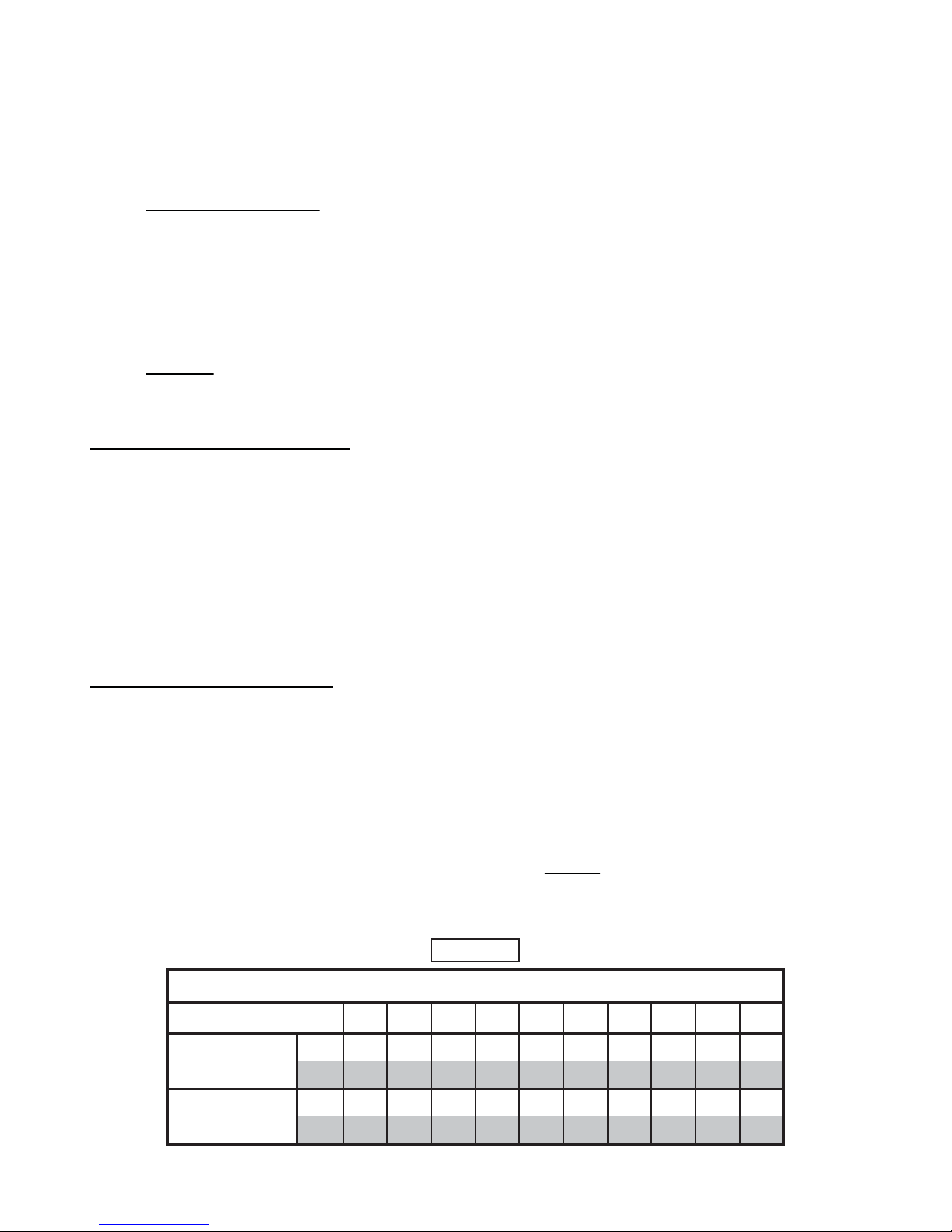
8.6 On the electronic aquastat (marked "WATER TEMPERATURE"), select the maximum water temperature
required (1-10) by the type of installation. Please see Table 6 below for the temperature obtained
according to the knob position. The minimum water temperature is reset automatically by the outdoor
sensor. Please see the variation graph in Fig 5.
Table 6
Water Temperature controlled by Electronic Aquastat
Set-point
Maximum
temperature
Minimum
temperature
10987654321
°C
88 81 75 67 58 50 45 42 39 36
°F
190 178 167 153 137 122 113 107 102 97
°C
48 48 48 45 40 38 34 31 29 28
°F
118 118 118 113 104 100 93 88 84 82
Page 5
Page 8
Electronic Aquastat
MAXIMUM
WATER TEMPERATURE
MINIMUM
WATER TEMPERATURE
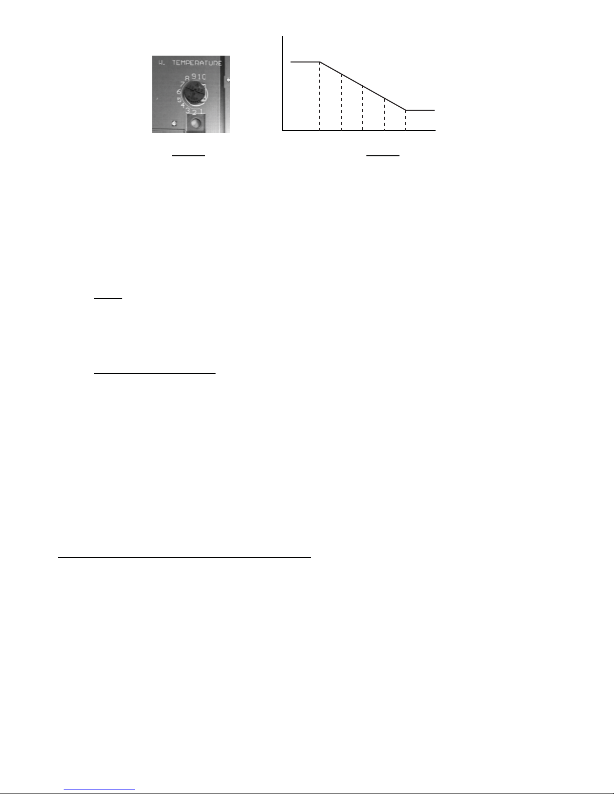
°F +14 +23 +32 +41 +50
Fig. 4 Fig. 5
8.7 The outdoor sensor will :
a) Maintain the selected maximum water temperature when the outdoor temperature is at +14° F or
colder.
b) Automatically and proportionally compensate by varying the water temperature between the
maximum and minimum when the outdoor temperature is between +14°F and +50°F.
c) Maintain the minimum water temperature when the outdoor temperature is between +50°F and
+68°F.
d) Prevent boiler operation above +68°F.
NOTE : If you choose not to use the outdoor sensor, don't connect it to the "OT / OT" terminals nor jumper
these terminals. You will not use this feature and the water will simply be maintained at the maximum
selected temperature.
8.8 Connect the thermostat or the zone valve end switch wires to "C" and "W1" terminals on the electronic
board. Power stealing thermostats require an isolation relay (not included).
8.9 Circulating Pump Control. The "P / P" terminals are connected to dry contacts of a relay (capacity up
to 1 HP) and are used to start the pump. This relay is switched ON with the first heating step and OFF
after the last one. A separate 120V / 1Ø service must be provided from the electrical panel to the boiler
for the pump. For Electric Boiler only systems, refer to the wiring diagram. For Electric Boiler with fossil
fuel backup, see the diagram on page 23 labeled ‘PUMP WIRING WITH FOSSIL FUEL BACKUP
BOILER’ as the pump must also run when another source of heat is selected.
Follow the extra steps dedicated to a FFB installation in the start-up sequence.
8.10 Set the room thermostat heat anticipator (when available) to 0.2 Amperes.
8.11 If the system is used with Load Management control, connect the Utility signal to "S1 / S2" terminals.
A closed contact enables the boiler, an open contact disables the boiler.
8.12 The installation is now ready for start-up procedure and testing.
9 Start-up procedure and test sequence
Do not energize electrical elements prior to purging system and verifying proper water circulation
Double check the following carefully :
9.1 All wiring and plumbing is complete.
9.2 Pipes have been cleaned, the system has been flushed and filled again.
9.3 Without powering the entire unit, install a jumper between the "P / P" terminals (using proper gauge of
wire) and switch the pump breaker ON as to let the pump run alone. Verify that the pump is running freely
and check for leaks. During this test, a lot of bubbles will travel through the system and air will be
eliminated by the automatic vents. You can accelerate the process by purging the radiators manually.
Shut off the pump breaker at the panel, then remove the jumper between the "P / P" terminals.
9.4 The pressure in the system has been stabilized at approximately 15 PSI (104 kPA).
9.5 The entire system is now almost free of air.
9.6 The room thermostat anticipator (when available) has been set at 0.2 Amperes.
9.7 Switch the boiler breaker ON at the main panel.
Page 6
Page 9

9.8 Set the thermostat above the room temperature. The system should start.
9.9 Make sure the pump starts running as soon as the system starts.
9.10 Heating stages will be switched ON in sequence at 30 second intervals, confirmed by green lights on the
left hand side of the PC board on the TH600 or by red lights on the right hand side on the D22-B.
9.11 Wait for two minutes and measure the current drawn by the boiler and compare it with the one shown on
the nameplate.
9.12 When the required maximum water temperature selected on the aquastat (0-10) or controlled by the
outdoor sensor is reached, the electronic controller will modulate the boiler capacity to maintain the water
temperature, as long as the demand for heating is not satisfied. The bottom green light flashes
continuously on the TH600 or one of the red lights on the D22-B to indicate that the boiler is maintaining
the setpoint. When the room thermostat is satisfied, the heating stages will come OFF in sequence at 5
second intervals.
9.13 Set the room thermostat to the desired set point.
9.14 The boiler is now ready and functional.
Extra test steps for Electric with Fossil Fuel Backup Boiler installation
9.15 Disconnect the room thermostat wires from the existing boiler and connect them to "C" and "W1" terminals
on the electronic board of the electric boiler.
9.16 Connect two (2) wires from "B / B" control terminals of the electronic board on the electric boiler to the
T T (thermostat) terminals of the existing boiler.
9.17 Terminals "S1 / S2" on the electronic board should receive the utility Load Management Control wires.
9.18 Connect the pump terminals "P / P" in parallel to the existing thermostatic pump control as per wiring
diagram on page 23 to allow the operation of the pump in any of the "Dual-Energy" modes selected.
9.19 When the system is opperating in Fossil Fuel mode, the supply water temperature of the fossil fuel boiler
should never exceed 190°F which may trip the manual high limit in the electric boiler.
10 Test sequence for FFB Boiler systems
10.1 An FFB boiler is supplied with a three-position mode selector switch. Because of differences in regional
regulations, the electronic board has been factory set so as to allow the activation of the electric mode
depending on the unit destination. In the "Gas / Oil" position the thermostat will call upon the gas or oil
boiler or furnace to maintain the house temperature at the desired level. The "Dual-Energy" mode gives
automatic control to the outdoor sensor or alternate switching signals from the local utility for Load
Management control. When the Load Management contacts are closed, the "Electric" mode is selected.
When these contacts are open, the "Gas / Oil" mode is selected. A green pilot light indicates the mode
that has been selected.
OIL / GAS
DUAL ENERGY
Fig. 6
Heating by means of Fossil Fuel Boiler
Do not use the middle position
Dual-Energy mode - Electric is primary source of heat.
May be controlled by utility company.
Page 7
Page 10

10.3 Simulate a heating demand by setting the thermostat higher than the room temperature.
10.4 Switch the mode selector to position and check that the burner responds to the thermostat demand.
10.5 Switch the mode selector to the "Dual-Energy" position . Install a jumper between terminals "S1 / S2";
the electric mode is automatically selected. The pump will start and the heating stages will be switched
ON in sequence at 30 second intervals. Measure the current drawn by the boiler and compare it with the
one shown on the nameplate. If you remove the jumper from terminals "S1 / S2", the system should switch
back to the "Oil / Gas" mode.
10.6 Switch the mode selector to the desired position and set the room thermostat to the desired temperature.
10.7 Your boiler is now ready and functional.
11 Installation examples
11.1 Installation A shows a Thermolec electric boiler in a Full-Electric Configuration.
11.2 Installation B shows a Thermolec electric boiler in a FFB-Series Configuration.
Water is always passing through both boilers even if only one heat source is selected at a time.
11.3 Installation C shows a Thermolec electric boiler in a Primary/Secondary Piping Configuration.
Water is pumped through multiple zones (more than two equally sized zones).
12 Position and electric values of heating elements
Standard values of heating elements at 240 Volts are 3kW, 5kW, 5.75kW, 8.75kW & 10 kW. Please refer
to the following sketches and tables to find the position and test value in ohms of each element. Please
ensure you disconnect the element wires completely before you make the resistance reading.
13 Replacement of heating elements
Heating elements nuts and cover bolts have been factory torqued with a calibrated tool. Please make
sure you have a torque driver and the proper sockets handy before you open the boiler tank.
Elements nuts should be torqued at :
130 inch-pound (in-lbs) or equivalent
Please ensure you use the double wrench method (i.e. an open key inside of the tank to hold the
element hexagon flange firmly and the torque wrench outside). Don't let the element turn while tightening
or it may become damaged.
Cover hex bolts should be torqued at :
70 inch-pound (in-lbs) or equivalent
Please make sure to tighten all nuts by hand first, then tighten them as per fig. 8 and finally apply the
proper torque with the torque wrench. Resist the feeling that the bolts could get torqued more (even if
possible) because that action would simply squash the silicone gasket to the point where it would
eventually lose all its resiliency and sealing properties.
Keep in mind that an equal torque is far more important.
Page 8
Page 11

3
C
5
L
Torque Element
Nuts at
130 inch-lbs
Torque Cover
1
Cylinder
Output
8
C
L
7
2
Bolts at
6
70 inch-lbs
14 Warranty
Thermolec Ltd. warrants against defects in materials and workmanship the heat generator casing of its boiler and
the heating elements for ten ( 10 ) years and all other components for two ( 2 ) years after date of original
installation.
Pressure/Temp. Gauge
4
Fig. 8
Any claim under this warranty shall be considered only if the product has been installed and operated in
accordance with Thermolec’s written instructions.
Any misuse of the system or any repair by persons other than those authorized by Thermolec, carried out without
its written consent, voids this warranty.
Thermolec’s responsibility shall be limited in any case to the replacement or repair, in its factory or in the field, by
others chosen by Thermolec, at its option, of such boiler or parts thereof, as shall prove to be defective within the
warranty period.
Thermolec Ltd. will not be held responsible for labor, accidental or consequential damages, nor for delays, nor for
damages caused by the replacement of the said defective boiler.
Page 9
Page 12

V
W
4
L
C
1
Four Element Configuration
3000 19.2 CBLR065
5000 11.5 CBLR055
Three Element Configuration
3
L
C
Cylinder
Output
3
L
C
L
C
Cylinder
Output
2
Front of cylinder
1
2
Front of cylinder
Elements Position, Electric Data and Part #
Position 1 Position 2 Position 3 Position 4
olts / Total
3000 19.2 CBLR065
Watts Ohms Part # Watts Ohms Part # Watts Ohms Part # Watts Ohms Part #
3.00
Height Phases K
5750 10.0 CBLR060
5000 11.5 CBLR055
5.00
5000 11.5 CBLR055 3000 19.2 CBLR065
6.00
8.00
5750 10.0 CBLR060 3000 19.2 CBLR065
5000 11.5 CBLR055 5000 11.5 CBLR055
9.00
10.00
12.00 5750 10.0 CBLR060 5750 10.0 CBLR060
240/1
13"
Cylinder
18.00 5000 11.5 CBLR055 5000 11.5 CBLR055 5000 11.5 CBLR055 3000 19.2 CBLR065
15.00 5000 11.5 CBLR055 5000 11.5 CBLR055 5000 11.5 CBLR055
20.00 5000 11.5 CBLR055 5000 11.5 CBLR055 5000 11.5 CBLR055 5000 11.5 CBLR055
5750 10.0 CBLR060 5750 10.0 CBLR060 5750 10.0 CBLR060 5750 10.0 CBLR060
23.00
27.00 8750 6.6 CBLR058 8750 6.6 CBLR058 5000 11.5 CBLR055 5000 11.5 CBLR055
240
10000 5.8 CBLR059 10000 5.8 CBLR059 5000 11.5 CBLR055 5000 11.5 CBLR055
35.00 8750 6.6 CBLR058 8750 6.6 CBLR058 8750 6.6 CBLR058 8750 6.6 CBLR058
40.00 10000 5.8 CBLR059 10000 5.8 CBLR059 10000 5.8 CBLR059 10000 5.8 CBLR059
30.00
240/1
23"
Cylinder
3000 19.2 CBLR065
3000 19.2 CBLR065 3000 19.2 CBLR065
3000 19.2 CBLR065 3000 19.2 CBLR065
3.00
6.00
9.00
240/1
13”
TMB
L
C
Two Element Configuration
3000 19.2 CBLR065 3000 19.2 CBLR065
11.00
L
C
One Element Configuration
Cylinder
1
2
Cylinder
Output
1
Cover Top View
Pressure\Temp. Guage Pressure\Temp. Guage Pressure\Temp. Guage
Front of cylinder
L
C
Pressure\Temp. Guage
Front of cylinder
L
C
Page 10
Cylinder
Output
Page 13

Position 1, 2, 3
208
Elements Position, Electric Data and Part #
24.00 6 4000 10.8 CBLR052
30.00 6 5000 8.7 CBLR053
Volts / Total V noitarugifnoC#/ tlo
Height Phases KW element élém. Watts Ohms Part #
208/3
23" Cyl.
13" Cyl. 18.00 6 3000 14.4 CBLR051
36.00 6 5750 7.5 CBLR054
277
30.00 3 10000 7.7 CBLR062
24.00 3 8000 9.6 CBLR061
480/3
13" Cyl. 18.00 3 6000 12.8 CBLR056
23" Cyl.
Page 11
40.00 3 13300 5.8 CBLR064
35.00 3 11600 6.6 CBLR063
Page 14

ALL-ELECTRIC INSTALLATION
(Illustration A)
SUPPLY
POWER SUPPLY
120V / 1Ø
PUMP POWER
LOAD
CONTROL
SENSOR
MANAGEMENT
OUTDOOR RESET
ROOM THERMOSTAT
CIRCULATING PUMP
TEMPERATURE /
PRESSURE GAUGE
BLEEDING VALVE
SAFETY VALVE
VALV E
MAINTENANCE
AIR VENT
AUTOMATIC
E
R
U
T
A
N
R
O
É
I
P
S
S
M
E
E
R
T
P
/
/
E
E
R
R
U
U
T
S
A
S
R
E
E
R
P
P
M
E
T
AIR
PURGER
VALV E
BOILER
ELECTRIC
MAINTENANCE
DRAIN
CONNECTION
WATER
FLOW
RETURN
DRAIN OR
PURGE VALVE
VALV E
MAINTENANCE
SUPPLY
VALV E
SHUT-OFF
Page 15
PRESSURE
WATER FEED
TAN K
EXPANSION
REDUCING VALVE
NOTE: Refer to table 4 for minimum flow rates based on boiler kW. Primary/secondary boiler piping is
recommended when system has more than two equally sized zones.
Page 15

DUAL-ENERGY SERIES INSTALLATION
(Illustration B)
LOAD
SENSOR
OUTDOOR RESET
CONTROL
MANAGEMENT
POWER SUPPLY
ROOM THERMOSTAT
CIRCULATING PUMP
CONTROLLER
DUAL-ENERGY
TEMPERATURE /
PRESSURE GAUGE
SAFETY VALVE
BLEEDING VALVE
VALV E
MAINTENANCE
AIR VENT
AUTOMATIC
E
R
U
T
A
N
R
O
É
I
P
S
S
M
E
E
R
T
P
/
/
E
E
R
R
U
U
T
S
A
S
R
E
E
R
P
P
M
E
T
AIR
PURGER
VALV E
MAINTENANCE
BOILER
ELECTRIC
DRAIN
CONNECTION
WATER
PUMP
FLOW
CONTROL
BOILER
OIL / GAS
VALV E
MAINTENANCE
BURNER
RETURN
DRAIN OR
PURGE VALVE
VALV E
MAINTENANCE
SUPPLY
VALV E
SHUT-OFF
PRESSURE
WATER FEED
Page 17
TAN K
EXPANSION
REDUCING VALVE
NOTE: Refer to table 4 for minimum flow rates based on boiler kW. Primary/secondary boiler piping is
recommended when system has more than two equally sized zones.
Page 16

PRIMARY / SECONDARY PIPING INSTALLATION
T
E
M
P
E
R
A
T
U
R
E
/
T
E
M
P
É
R
A
T
U
R
E
P
R
E
S
S
U
R
E
/
P
R
E
S
S
I
O
N
SUPPLY
AIR
PURGER
BLEEDING VALVE
SAFETY VALVE
ROOM THERMOSTAT
WATER FEED
PRESSURE
REDUCING VALVE
TEMPERATURE /
PRESSURE GAUGE
RETURN
EXPANSION
TAN K
CIRCULATING PUMP
ZONE PUMP
ZONE PUMP
ZONE PUMP
ZONE PUMP
MAINTENANCE
VALV E
AUTOMATIC
AIR VENT
LOAD
MANAGEMENT
CONTROL
POWER SUPPLY
120V / 1Ø
PUMP POWER
SUPPLY
MAINTENANCE
VALV E
MAINTENANCE
VALV E
DRAIN OR
PURGE VALVE
SHUT-OFF
VALV E
OUTDOOR RESET
SENSOR
ELECTRIC
BOILER
WATER
FLOW
DRAIN
CONNECTION
(Illustration C)
Page 19
NOTE: Refer to table 4 for minimum flow rates based on boiler kW. Primary/secondary boiler piping is
recommended when system has more than two equally sized zones.
Page 17

PUMP WIRING WITH FOSSIL FUEL BACKUP BOILER
120 VAC
OUTPUT W/ HEAT CALL
120 VAC
POWER
SUPPLY
HOT
COM
V
120V COIL
V
NO
HOT
CIRCULATION
PUMP
COM
ELECTRIC BOILER
CIRCULATION PUMP
P
P
Page 21
Page 18

Page 19

Page 20

April 9, 2010
Electric Boiler Troubleshooting Guide
Call for heat and boiler doesn’t start, no lights on circuit board. Try the following:
1. Confi rm that the boiler is connected to 240/1 power, main panel breakers are ON, breakers
supplying boiler in panel are ON.
2. Boiler circuit breakers are ON.
3. Check line side of transformer for 240 volts. If yes, continue. If no, check for 240VAC at circuit
breaker.
4. Check low voltage side of transformer for 24 VAC. If yes, continue. If no, change transformer.
5. Check for 24 VAC from fuse to circuit board. If yes, continue. If no, change fuse.
6. If outdoor sensor is attached to OT/OT on boiler circuit board, is outdoor temperature below
68°F? If outdoor temperature is 68°F or more, disconnect one leg of wires to OT/OT. Do not
jumper OT/OT.
7. Confi rm that load management control contact is wired to S1/S2 terminals on boiler circuit
board and load management contact is closed, or jumper S1/S2. Boiler will not start if S1/S2 is
open.
8. Confi rm that thermostat or zone valve end switch is wired to C/W1 terminals on boiler circuit
board and that boiler is getting a good call for heat, or jumper C/W1.
9. Turn OFF circuit breakers at boiler. On upper left corner of circuit board are two red wires
connected to supply water sensor on boiler tank. Carefully disconnect red wire connections
from board. Turn ON circuit breakers. If boiler starts, turn OFF circuit breakers and replace
supply water sensor. If boiler doesn’t start, replace circuit board.
Call for heat, circuit board lights come on but no heat or insuffi cient heat. Try the following:
1. Check amp draw at boiler circuit breakers. If amp draw is less than rating on boiler label,
continue to next step. If amp draw is correct, turn OFF circuit breakers and check pump
operation, confi rm system design, heat loss, boiler sizing, system water level, etc.
2. Check back-up contactor. Set meter to volts AC and measure for voltage on power wires out
of contactor going to elements/relays. If 240VAC, go to next step. If not 240VAC, check for
24VAC at coil of back-up contactor. If no 24VAC, check for 24VAC across high limit sensor on
tank. If 24VAC, reset manual high limit or, if auto high limit, change high limit. If no 24VAC,
check wiring at high limit.
3. Check for 24V DC from circuit board to coil of element relays - smaller two screws on solid
state relay, terminals labeled coil on DC relays. Make sure + probe on meter to + terminal on
SSR and – to –. If no DC voltage to relays, check wiring harness connection to circuit board.
If DC voltage at relay, set meter to volts AC and check contact side of relay. If solid state
relay, put probes on SSR L1 and T1 – larger two screws on SSR. If DC relays, put probes on
terminals labeled contacts. If 0 voltage, relay contact is closed, go to step 4. If 240VAC at
relay contact, it is failed open, change relay.
4. Turn OFF circuit breakers. Check for continuity at boiler elements. If no continuity, change
element.
Page 23
Page 21

Call for heat, boiler starts and back-up contactor is noisy. Try the following:
1. Check for 24VAC out of transformer to contactor. If less than 24VAC, change transformer. If
24VAC, contactor is defective or contacts are dirty. Continue.
2. Turn OFF boiler circuit breakers. Disconnect wires to contactor, remove contactor from boiler,
remove two screws from bottom metal plate on contactor, carefully remove coil and magnetic
core, carefully clean surface of magnetic contacts with emery cloth. Reassemble and reinstall
contactor. Remove all debris, metal shavings, etc. from inside of boiler cabinet. Restart boiler.
If contactor noise continues, replace contactor.
Call for heat, boiler starts but pump doesn’t run. Try the following:
1. Check for 120VAC from main electrical panel to pump. Pump must get power from the panel.
2. Route 120VAC from panel to pump through boiler. Run line leg of 120VAC through PP
terminal on boiler. When boiler starts, relay connected to PP will close and start pump.
3. If pump is powered from panel and run through PP as described above and pump does not
start when boiler starts, check for continuity on contact side of PP relay. If not closed, replace
PP relay.
Call for heat, boiler starts, call for heat ends (no lights on board) and boiler continues to heat.
Try the following:
1. Confi rm that the call for heat has ended, disconnect wires to C/W1.
2. Check for amp draw at each element circuit. If there is amp draw, check for 240V AC on
contact side of element relay. If there is 0 voltage, relay has failed closed, change relay.
3. Check for amp draw and if some amp draw but less than full rated amp draw: Set meter to
ohms and check element drawing amps. If element reads less than rated ohms, change
element. If element reads proper ohms, change relay.
Call for heat and boiler tank is “noisy”. Hissing, percolating or knocking noise from tank:
1. Most common cause of boiler tank noise is improper fl ow. Refer to installation manual for
proper GPM based on kW size of boiler.
2. If proper GPM fl ow rate through boiler, noise can be caused by sediment build-up on elements.
Check for build-up on outside surface of elements.
Page 24
Page 22

Effective: 11.1.11
B-5 B-6 B-8 B-9 B-10 B-12 B-15 B-18 B-20 B-23 B-27 B-30 B-35 B-40 B-3 B-6 B-9 B-11
16-04-001 TMB D-22 Control Board 1 1 1 1
10-02-0049 B/U Contactor 50 amp (lug style) 1 1
10-02-005 B/U Contactor 50 amp (spade style) 1 1 1 1 1 1 2 2 2 2 3 3 4 4 1 1
10-02-006 Element Activation Relay 1 1 1 2 3 3 2 2
10-02-006 Pump Relay 1 1 1 1 1 1 1 1 1 1 1 1 1 1 1 1 1 1
17-02-101 3 kw element 1 3 1 1 2 3 2
17-02-102 5 kw element 1 1 2 3 3 4 2 2 1
17-02-103 5.75 kw element 1 2 4
21-00-001 8.75 kw element 2 4
21-00-002 10 kw element 2 4
17-02-104 Temperature Pressure Gauge 1 1 1 1 1 1 1 1 1 1 1 1 1 1 1 1 1 1
17-02-105 Pressure Relief Valve 1 1 1 1 1 1 1 1 1 1 1 1 1 1 1 1 1 1
10-02-004 Manual Hi Limit Reset 1 1 1 1 1 1 1 1 1 1 1 1 1 1 1 1 1 1
17-02-107 Tank Temp. Sensor 1 1 1 1 1 1 1 1 1 1 1 1 1 1 1 1 1 1
17-02-109 TH-600D FFB Control Board 1 1 1 1 1 1 1 1 1 1 1 1 1 1
17-02-10959 (Upgrade) FFB Dual Temp. Board
17-02-110 TH-600M Mono Control Board
17-02-11095 (Upgrade) Mono Dual Temp. Board
17-02-1115 Circuit Breaker 20 amp 1
17-02-111 Circuit Breaker 30 amp 1 1
17-02-112 Circuit Breaker 40 amp 1
17-02-113 Circuit Breaker 50 amp 1 1 1 2 4 1
17-02-114 Circuit Breaker 60 amp 1 1 1 1 2 2 1 3 4 1
17-02-11440 SSR Relay 40 amp 1 1 1 1 1 2 3 4 4 4
17-02-115 SSR Relay 50 amp 4 4 4 4
17-02-116 Control Transformer 30 VA 1 1 1 1 1 1 1 1 1 1
21-00-006 Control Transformer 50 VA 1 1 1 1
17-02-117 Control Fuse 2 amp 1 1 1 1 1 1 1 1 1 1 1 1 1 1 1 1 1 1
17-02-119 Outdoor Sensor 1 1 1 1 1 1 1 1 1 1 1 1 1 1 1 1 1 1
21-00-004 Stainless Steel Tank Gasket 1 1 1 1 1 1 1 1 1 1 1 1 1 1 1 1 1 1
Diagrams on next page are for parts identification and terminology purposes.
All Boilers contain different parts and parts breakdown should be used to identify exact part number and quantity in each unit.
TMB Parts
FFB Parts
Description
Part Number
Page 23

1 Control Board 1 Control Board/Module
3A SSR Relays 3 Back Up Contactor
3B Element Activation Relay 4 Elements
5 Back Up Contactors 6 Transformer
7 Control Transformer 7 Circuit Breaker
8 Pump Relay 12 Fuse
13 Circuit Breakers 14 Pump Relay
14 Manual Hi Limit Reset 16 Manual Hi Limit Reset
19 Elements 17 Tank Temperature Sensor
22 Tank Temperature Sensor 18 Outdoor Reset
24 Fuse
26 Outdoor Reset
27 Temperature Pressure Gauge
FFB Style Boiler
TMB Style Boiler
Page 24

7878 12th Ave. South
Bloomington, MN 55425
Phone: (952) 854-4400
Fax (952) 854-4441
Representing the following quality manufacturers:
Thermolec: Electric heating products including boilers, plenum heaters and duct
heaters. (In Stock) www.thermolec.com
Summeraire:Residential and Light Commercial air-to-air heat recovery ventilators
and accessories (In Stock) www.summeraire.com
Soler & Palau: Residential and Commercial air movement products.
www.solerpalau-usa.com
Salo Manufacturing: Residential and Commercial fiberglass bathing systems, new construction, remodel and ADA compliant surrounds. www.salomfg.com
Dimplex: Residential, Commercial and Industrial electric heat products.
www.dimplex.com/electromodeproducts.asp
Trion: Air Bear media air cleaners, electric air cleaners, and humidifiers.
www.trioninc.com
ecobee: Web connected Smart Thermostats and Energy Management Systems for residential and commercial applications. www.ecobee.com
Premier One: Residential and Commercial Germicidal & Ozone products, HEPA Filtration and Polarized Media filtration. www.premieroneproducts.com
EPS Make-up Air: Systems up to 1360 cfm with electric pre-heat. (In Stock)
www.epsalesinc.com
FAMCO: Motorized dampers, back draft dampers, metal or plastic wall and roof vents
and other products. www.famcomfg.com
EP Sales, Inc. operates out of our office-warehouse facility in Bloomington, MN. Items marked (In Stock) are buy/sell
products and they are stocked in our warehouse. Territories covered include MN, WI, ND, SD and IA. All product lines
are sold through wholesale distribution.
Please visit our website www.epsalesinc.com for more information
January 2012
 Loading...