

Page 1

Thermokon Sensortechnik GmbH - www.thermokon.de - email@thermokon.de
Operating Instructions
Radio Receiver
SRC-Ethernet
Version 1.52, 09.02.2006
Page 2

Interface description SRC-Ethernet
Thermokon Sensortechnik GmbH Page 1
1 Introduction.......................................................................................................3
1.1 Product Overview..................................................................................................3
1.2 Product Specification.............................................................................................4
2 Installation.........................................................................................................5
2.1 Hardware Installation.............................................................................................5
2.2 Software Installation..............................................................................................5
3 Configuration Of Receiver ...............................................................................6
3.1 Software Specification...........................................................................................6
3.2 General Notice.......................................................................................................7
3.3 Menu .....................................................................................................................7
3.4 Adjustments...........................................................................................................7
3.4.1 Automatic Search of Receiver........................................................................8
3.4.2 Manual Scan for Receiver..............................................................................8
3.4.3 Network Adjustments .....................................................................................8
3.4.4 Description .....................................................................................................9
3.4.5 Summary........................................................................................................9
3.5 Sensors...............................................................................................................11
3.5.1 Learning-in of Sensors.................................................................................11
3.5.1.1 Manual Learn-in of an Address.............................................................12
3.5.1.2 Learn-in of an Address by means of the Learn-in Button...................... 12
3.5.1.3 Learn-in of Addresses by an Address Default.......................................13
3.5.2 Set-up of an Address Default .......................................................................13
3.5.3 Deleting of Sensors.....................................................................................13
3.5.4 Additional Information on Sensor ................................................................. 13
3.5.5 Monitor Timer...............................................................................................15
3.5.6 Summary......................................................................................................16
3.6 Logging of Data...................................................................................................17
3.6.1 Selection.......................................................................................................17
3.6.2 Scaling .........................................................................................................18
3.6.3 Monitor Interval.............................................................................................18
3.6.4 Log type........................................................................................................18
3.6.5 Start..............................................................................................................18
3.6.6 Break............................................................................................................18
3.6.7 Stop..............................................................................................................18
3.6.8 Store.............................................................................................................18
3.6.9 Summary......................................................................................................19
4 Application of Radio Receiver.......................................................................20
4.1 Connection Set-Up..............................................................................................20
4.1.1 Server-Client by TCP ...................................................................................21
4.1.2 Client-Server by TCP ...................................................................................22
4.1.3. Connection Set-up by UDP-Protocol ...............................................................22
Page 3

Interface description SRC-Ethernet
Thermokon Sensortechnik GmbH Page 2
4.2 Receipt of Data....................................................................................................22
4.2.1 Data receipt by TCP-Protocol......................................................................22
4.2.2 UDP-Protocol ...............................................................................................23
4.3 Evaluation of Telegram........................................................................................24
4.3.1 Data Telegram..............................................................................................24
4.3.2 Time Error Telegram....................................................................................25
5 Trouble Shooting............................................................................................26
6 Glossary...........................................................................................................27
7 Changes...........................................................................................................30
Page 4

Interface description SRC-Ethernet
Thermokon Sensortechnik GmbH Page 3
1 Introduction
1.1 Product Overview
The SRC-Ethernet radio receiver is designed for receiving and processing telegrams of
Thermokon radio sensors belonging to the EasySens family as well as other devices,
transfering measuring values based on the EnOcean standard. By means of this
component it is possible to evaluate radio sensors by a PC or by an Ethernet capable
controller via the Ethernet (see picture 1). The protocols TCP or UDP can be used.
A CD with the configuration software is supplied along with the device. The software
provided allows the configuration of the IP-addresses, the learning-in of sensors to the
receiver and diagnosis possibilities of the learned-in sensors.
For the operation of the receiver, an additional external 868 MHz antenna with a FMEfemale connection is necessary. This antenna can be ordered separately as an accessory
with different connection lengths (2,5m/10m/20m).
Cool Heat Fan Sunblinds
Lamp
Lamp
Movement
detector
230V
M
868Mhz
868Mhz
868Mhz
868Mhz
Application SRW01
Window contact
State of window (Energy hold off)
for FanCoilControllers
Controller
with Interface Ethernet
...
IO Sunblind / Light
A
p
p
licati
o
n o
f T
hermo
kon p
r
odu
ct
s fo
r
Building Control Systems
Ethernet
Application SR04PST
Room Panel
Zone sensor temperature,
local temperature setpoint,
fan speed, bypass key
for FanCoilControllers
Applicati on SRC-Ether n e t
Radio receiver
Interface between third party controllers
or PC and radio sensors
via Ethernet (TCP/IP or UDP)
PC
Picture 1-1: Schematic layout
Page 5

Interface description SRC-Ethernet
Thermokon Sensortechnik GmbH Page 4
1.2 Product Specification
Product: Receiver for up to 30 radio sensor based on the
EnOcean standard
Standard: 10/100 Base-T Ethernet (Auto detection)
Protocol: TCP, UDP, IP, ARP, ICMP, Ethernet MAC
Power Supply: 230V AC 50/60Hz
Typical transmitting range: 30m in buildings with antenna
CE-conformity: 89/336/EWG Electromagnetical compatibility
73/23/EWG Low-voltage directive
EMV: EN60730-1 (2000) Interference
EN60730-1 (2000) Emitted interference
Product safety: EN60730-1 Autom. electr. control units and controllers
for domestic use and similar applications
Ambient temperature: 0...60°C
Rel. air humidity: 0...75%rH, not condensed
Store temperature: -20...70°C
Ethernet RJ45
RXD Radio
Learn Mode
Link
Active
230VACAntenna
SRC-Ethernet
105,0
90,0
Page 6

Interface description SRC-Ethernet
Thermokon Sensortechnik GmbH Page 5
2 Installation
2.1 Hardware Installation
By means of a network cable (e.g. FTP CAT.5) the receiver can be connected to the
Ethernet hub. If a point-to-point connection should be set-up, a connection by a crossover
cable (e.g. FTP CAT.5e) is necessary.
Detailed information on the installation and mounting can be found in the SRC-Ethernet
data sheet.
2.2 Software Installation
For the installation of the radio receiver the configuration software is needed. Therefore,
the setup file “setup.exe” contained on the attached CD must be started. For the
installation administrator rights are necessary. During the installation the screen
instructions must be followed.
After a successful installation, the configuration software can be started via the start
menu/programmes/Thermokon.
Operating systems supported: Windows9x; WindowsNT; WindowsMe; Windows2000;
WindowsXP; WindowsServer
Page 7

Interface description SRC-Ethernet
Thermokon Sensortechnik GmbH Page 6
3 Configuration Of Receiver
3.1 Software Specification
The configuration software mainly consists of three user interfaces (rider). In the first rider
“adjustments” the radio receivers currently connected to the Ethernet are displayed along
with their corresponding IP-addresses. The second rider “sensors” is used for the
configuration of the sensor addresses (sensor ID). In the third rider “logging of data” a
simple diagnosis function is available by which sensors can be logged. Picture 3-1 shows
the rider “adjustments” which is automatically activated after having started the program.
Picture 3-1: Rider ”Adjustments“
Page 8

Interface description SRC-Ethernet
Thermokon Sensortechnik GmbH Page 7
3.2 General Notice
Opening and Saving of Different Data Formats
The configuration software produces up to three data formats.
1. For each radio receiver a “*.dat“ file is produced in the sub directory “Dat” of the
configuration software. The file identification consists of “MAC_“ and the MAC-address
of the radio receiver (MAC_xxxxxxxxxxxx.dat). In the dat-file user information on the
receiver can be found.
2. The second file is an address default. By means of this default, network adjustments
and sensor IDs can be stored in the rider “sensors” by means of the button (see
picture 3-1). The address default file is saved by the ending “*.adr“ (name.adr).
Additionally, the description of the radio receiver as well as all sensor information
including the sensor IDs are stored in the address default. The address default can be
loaded by the button (see picture 3-1). Thus, it is possible to transfer sensor IDs of
one file to the radio receiver.
3. The third file is a log file (name.log). In this file with the ending “*.log“ measuring values
of logged sensors can be saved. Logging files can only be stored in the rider “logging
of data“.
Printing
By means of the button the description of the radio receiver and the sensor addresses
to the respective channels with the ORG-bytes and the sensor information are printed in
the rider “adjustments“ and “sensors“. In the rider “logging of data” the diagram of the
screen window is printed by means of the printing button.
3.3 Menu
The menu consists of the points “Firmware“, “About“ and “Help“.
In normal operations of the radio receiver a new firmware is not essential. If an update of
the firmware devices should become necessary, the current firmware file can be loaded to
the radio receiver via the menu point “Firmware”. In the menu „About“ information on the
manufacturer and the products can be found. Help relating to the program can be calledoff via the menu „Help“.
3.4 Adjustments
The construction of the rider “adjustments“ is shown in picture 3-1. The individual
functions are explained in the following chapters.
Page 9

Interface description SRC-Ethernet
Thermokon Sensortechnik GmbH Page 8
3.4.1 Automatic Search of Receiver
After having started the configuration software the program automatically scans the
network for radio receivers. The result of the receivers found is shown in the “receiver list”.
If no receivers are displayed, the installation of the devices should be verified. The
respective MAC-addresses of the radio receivers are displayed. After the browsing, the
adjustments of the first device are shown as a standard. By clicking to the corresponding
MAC-address in the receiver list the device is selected. The IP-adjustment of the device is
displayed and can be changed. Via the button “Search SRC” the network scan for
receivers is started manually.
3.4.2 Manual Scan for Receiver
In order to search a special radio receiver with a known IP-address, the field “Direct IP
search“ must be activated. The requested IP can be entered and searched via the “SRC
search” button.
The radio receiver found before by means of the automatic search, are deleted from the
receiver list and the radio receiver with the requested IP address is displayed, provided it
is existing in the network.
3.4.3 Network Adjustments
In the fields “SRC IP“, “SRC Subnet“, “Gateway“, “Server IP“ and “Port“ the network
address of the receiver can be configured.
The “SRC IP“ is the network address of the radio receiver. With connections via a router
the subnet mask in the field “SRC Subnet” as well as the address of the corresponding
router must be entered in the field “Gateway”.
In the field „Server IP“ the target address to which the device should send the data is
mentioned. In the fields “Port” the ports are entered over which the communication should
be made. With a client and server connection, the ports of the receiver and the server
must be identically. When having a connection via UDP, different ports must be set up. If
for a later Ethernet data transfer an address should be allocated by the network server, the
“DHCP Modus” must be activated. Via the option button “SRC-Client“ and “SRC-Server“
the required connection can be set up. By means of “UDP-Protocol“ and “TCP-Protocol“
the required protocol of the radio receiver is selected.
If the configuration was changed, they must be transmitted to the device by means of the
button “SRC update“.
Attention: For learning-in sensors respectively for the logging of learned-in sensors,
the IP-address of the local PC, on which the configuration software is installed,
must be entered in the field “Server IP”. Otherwise, no connection between the
receiver and the configuration software can be set up. Later, this address is
replaced by a target address of the Ethernet connection, to which the radio sensor
should send. The IP address of the local PC is displayed in the field “Local IP”.
Page 10

Interface description SRC-Ethernet
Thermokon Sensortechnik GmbH Page 9
3.4.4 Description
In this text field a description of the radio receiver can be entered, e.g. the mounting place
of the radio receiver. The current version of the radio receiver is displayed in the field
“Version”. In the field “Telegram received”, the latest telegram received of the current
receiver is displayed. By means of this field, it can be recognized whether the local PC
has set up a connection to the radio receiver. If the server IP is unequal to the local IP, no
connection between the local PC and the receiver was set up. Thus, the field “Telegram
received” remains empty. It is not possible to learn-in sensor IDs or to logg them.
3.4.5 Summary
The flow diagram in picture 3-2 shows the operating steps which must be effected for the
installation of the SRC-Ethernet radio receiver. After having installed the device, the
network adjustments must be configured. If the sensor IDs should be set up and monitored
by the local PC, the “Server IP“must be equal to the “Local IP“ of the PC. If the sensor
IDs are adjusted, the requested target address to which the radio receiver should send, is
entered to the “Server IP“.
Page 11

Interface description SRC-Ethernet
Thermokon Sensortechnik GmbH Page 10
Adjustment of IP
addresses
Connection via
Router/
Bridge?
Set-up of Subnet
Mask
Set-up of Gateway
Address
No
Monitor
Configuration
Server IP=Local IP
Server IP in normal
operation
Yes
No
Start
Yes
End
Picture 3-2: Adjustment of IP addresses
If all adjustments are successfully transfered, the sensors can be learned-in. As soon as a
telegram is displayed in the field “Telegram received“ in rider “Adjustments“, the
communication between local PC and radio receiver is working smoothly and the sensors
can be learned-in to the radio receiver. This is done in the rider “Sensors”
(see picture 3-3).
Page 12

Interface description SRC-Ethernet
Thermokon Sensortechnik GmbH Page 11
3.5 Sensors
The rider “Sensors“ (picture 3-3) contains an overview of the 30 sensor channels of the
receiver. One channel stands for a complete sensor including the different measuring
values e.g. temperature, setpoint etc.
Channels occupied already are marked in grey. The type of sensor and the sensor ID is
shown. Each sensor is clearly defined by its sensor ID and his type. The type of the sensor
is displayed in the so-called ORG-Byte of the telegram.
Picture 3-3: Rider Sensors
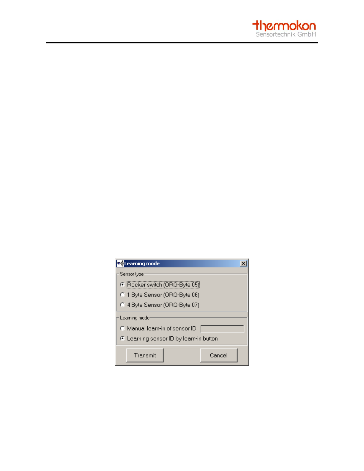
3.5.1 Learning-in of Sensors
In total 30 sensor addresses can be stored per receiver. A sensor is learned-in via the
„Learn symbol“ . The learn mode window is displayed (picture 3-4). In the window, the
sensor type of the sensor that should be learned-in must be chosen. At present, three
types are distinguished: Rocker switch, 1 Byte Sensor and 4 Byte Sensor. For example
Thermokon window contact SRW01 is a 1 Byte sensor whereas a Thermokon room
operating panel SR04PST is a 4 Byte sensor.
Page 13
Interface description SRC-Ethernet
Thermokon Sensortechnik GmbH Page 12
The actual „learning-in“ of the sensor can be made in two ways: either „manually“ or by
means of the „learn button” at the sensor.
(Notice: With a radio key (e.g. Peha) a rocker of the key is actuated instead of the learn
button.
3.5.1.1 Manual Learn-in of an Address
Select the sensor that should be learned-in in the learn mode window. Afterwards, mark
learn-in procedure „Manual learn-in of sensor ID“ and enter the sensor ID. The sensor ID
is 4 Byte long and must be mentioned in the hexadecimal format (e.g. 00005FAEh).
Confirm by actuating the button „learn-in“. The sensor address is allocated to the chosen
channel.
3.5.1.2 Learn-in of an Address by means of the Learn-in Button
Select the sensor type of the sensor that should be learned-in in the learn mode window.
Afterwards, select the learn-in procedure “Learn-in of sensor ID via Learn-in button” by
means of the learn-in button“ and confirm by “Learn-in“. The receiver is put in the learn
mode. As long as the receiver is in the learn mode, the status window is shown by a
progress bar graph display and on the receiver the learn mode LED is lighting up. The
receiver waits for a learn-in telegram of the sensor. Now, the learn-in button on the sensor
must be actuated. With a successful receipt of a learn-in telegram, the sensor is allocated
to the selected channel.
Picture 3-4: Learn mode window
Page 14
Interface description SRC-Ethernet
Thermokon Sensortechnik GmbH Page 13
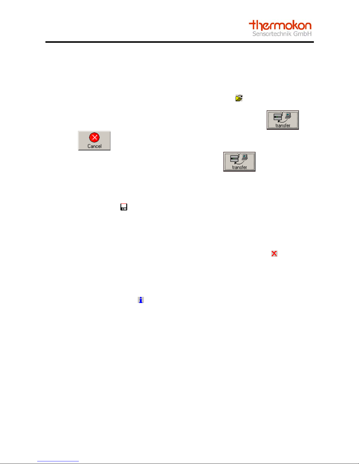
3.5.1.3 Learn-in of Addresses by an Address Default
By means of an address default, it is possible to load sensor addresses stored to the
configuration software. This function can be used for changing receivers without having to
learn-in the allocated sensors again. By means of the button in the rider “Sensors”,
address defaults are loaded. The addresses loaded are marked by white. After having
loaded an address default, all buttons are activated, expect of the button and
the button . By means of the abort button the address default loaded is warped
again. If an address default should be transfered, the button must be actuated.
3.5.2 Set-up of an Address Default
By means of the button an address default can be stored in the riders “Adjustments“
and “Sensors“. The address default contains the network information of the radio receiver
as well as the sensor information with the sensor IDs.
3.5.3 Deleting of Sensors
In order to delete a sensor address, it must be clicked on the “Erase button“ behind the
sensor that should be deleted. If the inquiry is confirmed, the address of the sensor is
erased.
3.5.4 Additional Information on Sensor
By means of the button “Info“ a monitor window is opened. Here, a description of the
respective sensor can be put in, e.g. installation place or function. The information is
automatically stored in the dat-file. As for a sensor, the field “status” shows whether the
sensor is still sending. If the sensor is sneding at this moment, but has failed from time to
time, an error message occurs in the monitor window. This message can be deleted by
means of the reset button. Furthermore, the data of the sensor are shown in the monitor
window. With a radio module the respective button actuated is shown. The meaning
respectively the occupancy of the data byte differs from manufacturer to manufacturer.
Thus it is indicated in the product specified data sheets. The monitor window is shown in
picture 3-5.
Page 15

Interface description SRC-Ethernet
Thermokon Sensortechnik GmbH Page 14
Picture 3-5: Monitor window for sensor and radio button module
By means of the “Info“-button in the rider “Sensors“ it can be recognized whether a sensor
is still sending. However, this only works if the monitor timer is active.
Info button is blue: Monitor timer not active
Info button is green: Sensor is sending
Info button is yellow: Sensor is sending, failed from time to time
Info button is red: Sensor is not sending
Page 16

Interface description SRC-Ethernet
Thermokon Sensortechnik GmbH Page 15
3.5.5 Monitor Timer
By means of the monitor timer it is possible to monitor sensors. A time interval, in which
the sensor must send, can be adjusted in order to avoid a time error telegram. If the
sensor does not send within this time interval, a time error telegram is sent which is
displayed on the monitor window.
The minimum monitor time amounts to 16 minutes, the maximum monitor time is 255
minutes.
Attention: Take care of the cyclically sending interval of a sensor (with Thermokon devices
it amounts to approx. 15 min as a standard). If the same is greater than the monitor timer,
a time error telegram is sent, although the sensor is still sending.
In picture 3-6 the monitor window is shown.
Picture 3-6: Monitor Timer
Page 17

Interface description SRC-Ethernet
Thermokon Sensortechnik GmbH Page 16
3.5.6 Summary
The operating steps for configuration of sensors are shown in the flow diagram in picture
3-7. For configuring sensor IDs, the server IP must be equal to the local IP, as otherwise
no connection between PC and receiver can be set up. To learn-in the sensor IDs, the
type of the sensor must be entered. Afterwards, the sensor can be learned-in by the learnin procedure. The finish of the sensor learning-in is made via the erase button of the
respective channel. Information on the sensor and its status can be displayed via the
information button.
For configuration of
sensor IDs adjust
ServerIP=LocalIP
Change into learn-
in mode window
via learn button of
the channel
Selection of learn
mode
Actuate Learn
button
Sensor / Roccer
switch is
learned-in
Erase sensor /
roccer switch via
erase button of the
channel
Sensor / roccer
switch is erased
Start
Learn-in of
Sensor ID?
Learn mode
manual?
Insert of Sensor IDYes Yes
No
Erasing of
sensor ID?
No
Yes
Info about
sensor / roccer
switch?
Change in monitor
window via info
button
Insert of
description
Setting back of
monitor timer
Change of
monitor timer?
Adjustment of
monitor timer
No
No
Yes
Yes End
No
Picture 3-7: Learning-in of Sensors
Page 18

Interface description SRC-Ethernet
Thermokon Sensortechnik GmbH Page 17
3.6 Logging of Data
The software has a simple diagnosis function for learned-in sensors. By means of this
function, measuring values respectively status can be logged and stored. This is done in
the rider “Logging of Data”, see picture 3-8.
Picture 3-8: Rider „Logging of Data“
3.6.1 Selection
In total five measuring values can be written. The allocation of the measuring values is
made via the selection of the respective channel and the corresponding data byte.
Example:
With a room sensor type SR04PST e.g. the multiple contact switch is transfered in data
byte 3 and the temperature setpoint in data byte 2. A detailed description of the respective
data bytes can be found in the product data sheets. Channel 01 (for the corresponding
sensor) and data byte 2 (for the corresponding setpoint).
Page 19

Interface description SRC-Ethernet
Thermokon Sensortechnik GmbH Page 18
3.6.2 Scaling
In the two fields behind the selection of the data bytes, the measuring value for each graph can be
scaled differently. The result is shown in the third field. This display is only designed for an easy
intepretating of the measuring values displayed. The entered scaling values have no influence on
the displayed values in the characteristics file.
Example: Scale the measuring range –20 to +60°C for an outdoor temperature sensor.
3.6.3 Monitor Interval
In the field “Monitor interval“ it is indicated in milli seconds in which interval the data are logged.
This monitor interval is the same for all 5 measuring values.
3.6.4 Diagram scalling
It is possible to scale the diagram. For this there is a min and a max value possible.
3.6.5 Log type
Tow types of logging data are possible:
1. Interval – Sensor dates are saved cyclical (Monitor interval)
2. Event – Sensor dates are saved when a telegram from the selected sensor is received
(only one channel could be logged)
3.6.6 Start
To start the logging function, the “Start button“
must be actuated. The actual value of the
chosen channel is shown in the diagram.
3.6.7 Break
If the logging should be interupted or proceeded any further at a later point of time, the “Break
button“
must be actuated.
3.6.8 Stop
In order to stop the recording, the “Stop button“
must be actuated.
In the break or stop mode the diagram can be scrolled.
3.6.9 Store
The data can be stored via the store button
in the rider „Logging of data“. It is only possible to
store data in a logg file if the logging procedure is stopped. By means of the logg file, it is possible
to import the stored values in a table calculation. A semicolon is used as a separator of the column.
Notice: At maximum 1000 values are stored and displayed in the configuration software. Bigger
data quantities are intermediately stored in a temporary directory. In the configuration software the
1000 values are deleted and the diagram starts again with 0. When storing the logg file, all
measuring values, logged so far, are stored.
Page 20

Interface description SRC-Ethernet
Thermokon Sensortechnik GmbH Page 19
3.6.10 Summary
In picture 3-9 the flow diagram for logging of data is displayed. First, adjust the requested
logg interval in the monitor interval. Afterwards select the channels and the data bytes that
should be displayed. The acutal value can also be scaled for an easier interpretation. The
scaled value is not shown in the diagram however.
Selection of
channels
Selection of data
bytes to be
displayed
Scaling of actual
value
Adjustment of
monitor interval
Start
Start of logg
function
Evaluation of data
End
Picture 3-9: Logging function
Page 21

Interface description SRC-Ethernet
Thermokon Sensortechnik GmbH Page 20
4 Application of Radio Receiver
The SRC-Ethernet radio receiver receives radio telegrams of sensors (temperature
sensors, radio keys etc.) based on the EnOcean standard and transfers the same to TCP
or UDP capable devices such as PC or controller. One of the basic functions is that switch
and control commands respectively measuring values are passed on to the corresponding
actuators. Furthermore the possibiltiy is given to visualize sensor information on the PC.
For communication the PC or an Ethernet capable controller must set up a connection via
the Ethernet to the radio receiver. If the connection was set up successfully, the data can
be processed.
After the receiver is configured, an application software is needed for data communication.
Following it is exemplariely shown how a PC builts up a connection to the receiver and
how it evaluates data by means of a Visual Basic 6 project.
The complete code for setting-up a connection and the code for receiving data are
included on the configuration CD of the radio receiver.
4.1 Connection Set-Up
A connection can be set up for all IP implementations via a standard window interface
„Winsock“. For setting-up a connection, this interface requires the respective IP-addresses
and ports of the devices that should communicate with each other.
The radio receiver can be run in the following mode:
1. Use of TCP-protocols
o Server-Client
o Client-Server
2. Use of UDP-protocols
o Server-Client
o Client-Server
Page 22

Interface description SRC-Ethernet
Thermokon Sensortechnik GmbH Page 21
The principle of a Server-Client connection is shown in picture 4-1. The TCP protocol is
used.
Client
Server
Send() Receive()
LocalPort()
Listen()
Connect()Accept()
Send()Receive()
Processing
Connection
Close()
Picture 4-1: Server-Client Connection
4.1.1 Server-Client by TCP
The radio receiver is configured in the client mode and a connection should be set-up via
the TCP protocol:
' Start server
Public Sub Form_Load() ‘Load of form (program request)
1. Winsock1(0).LocalPort = 4002 'Set port
2. Winsock1(0).Listen 'Wait for a connection to SRC
End Sub
' Take new connection
3. Public Sub Winsock1_ConnectionRequest(Index As Integer, ByVal requestID As Long)
If Winsock1(0).RemoteHostIP = "10.0.20.3" Then 'Approval of a SRCClient; “SRC_IP“
4. Load Winsock1(1) 'Load of connection
5. Winsock1(1).Accept requestID 'Acception of connection
End If
End Sub
1. Setting of local port of the server
2. Set server in a waiting mode
3. If the client is sending data the function Winsock1_ConnectionRequest is called off
in the server
4. The server initializes the connection by means of the command „Load“
5. Server accepts connection to the client
6. Connection is set up
The connection remains valid until it is not closed by the command
„Winsock1(Index).Close“. After the connection is set up, data can be communicated.
Page 23

Interface description SRC-Ethernet
Thermokon Sensortechnik GmbH Page 22
4.1.2 Client-Server by TCP
For the Client-Server mode a direct connection between server (radio receiver) and the
client (application) is set up by the command „Connect“. This can be done via the following
program lines.
' Set-up of Client-Server connection
Private Sub Form_Load() ‘Load of form (program request)
Winsock1.Connect "10.0.20.3", "4002" 'Set-up of conneciton; "SRC_IP", "SRC_Port"
End Sub
4.1.3. Connection Set-up by UDP-Protocol
In order to set up a connection to the radio receiver in the UDP mode, the IP address of
the radio receiver as well as the port of the radio receiver must be advised to the Winsock
interface. By the command „Bind“ the local port is communicated to the interface. Please
make sure that the port addresses of the local devices and the remote devices (radio
receiver) are different.
'Load of connection
Private Sub form_load()
Winsock1.RemoteHost = "10.0.20.3" 'Remote IP
Winsock1.RemotePort = "4002" 'Remote Port
Winsock1.Bind 4003 'Integration of UDP connection by local port
End Sub
4.2 Receipt of Data
4.2.1 Data receipt by TCP-Protocol
Data are received in the server- and client mode by the event „Winsock_DataArrival“ .
' Receiving of data
Public Sub Winsock1_DataArrival(Index As Integer, ByVal bytesTotal As Long)
Dim client As String
Winsock1(Index).GetData client 'Storing of data received in client
End Sub
The data received are read with the command „Winsock1.Getdata“ and stored for further
process in the variable „client“. In the example program the code for a server-client
connection is mentioned.
Page 24

Interface description SRC-Ethernet
Thermokon Sensortechnik GmbH Page 23
4.2.2 UDP-Protocol
In gerneral the UDP-Protocol can be used as the TCP-Protocol. However, the data
received cannot be displayed without another programming code. After the definition of the
variables „testdat“ and „client“ the field „getd“ is also new dimensioned.
The data received are read with the command “Winsock1.Getdata“ and stored for further
process in the variable „getd“.
The telegram is stored bitewise in getd (Byte 0 to 28). By means of a for-loop the telegram
is joined together and stored as a whole in „testdat“.
By means of the command „Chr“ the value of „getd(i)“ is converted into an ASCII sign.
'Data receipt
Private Sub Winsock1_DataArrival(ByVal bytesTotal As Long)
Dim testdat ‘Definition of variable testdat
Dim client ‘Definition of variable client
ReDim getd(0 To 28) As Byte 'New dimensioning of getd
Winsock1.GetData getd 'Storing of data received in getd
For i = 0 To 27 'Joining together of individual data received to a telegram
client = Chr(getd(i))
testdat = testdat + client
Next i
End Sub
Page 25

Interface description SRC-Ethernet
Thermokon Sensortechnik GmbH Page 24
4.3 Evaluation of Telegram
The radio receiver sends two different telegrams. The first one is the data telegram for
evaluation of sensors. The second one is a time error telegram. If the monitor timer is
activated and no radio telegram was received within an interval, a time error telegram is
produced and sent.
4.3.1 Data Telegram
In table 4-1 the Ethernet data telegram is shown. This telegram includes the measuring
values of the sensors received by the radio receiver. The first two byte (0;1) consist of the
preamble. The next byte (2) consists of a „Header identification“ and the length of the
telegram from the 3. byte. In the byte 3 „ORG“-Byte it is shown which sensor type is
concerns. A radio key has the identification „05“, a 1 Byte Sensor (e.g. a window contact)
has „06“ and a 4 byte sensor (e.g a room operating panel or a temperature sensor) has the
identification „07“. A sensor is clearly defined via his Org-Byte and his sensor ID.
In total 4 data bytes are received (bytes 4-7). The sensor ID is stored in the following 4
bytes.
In the status byte the status of the devices and the telgrams is mentioned.
Each sensor is stored in a channel of the radio receiver. It is shown in the 13 byte of the
telegram. The contents of the data byte is depending on the device and is thus described
in the respective data sheets of the sensors.
The telegram is transfered in the ASCII form.
Byte Description Value
0 Preamble “A5”
1 Preamble “5A”
2 H_SEQ length “0B”
3 ORG „05“/“06“/“07“
4 Data byte3 e.g. radio key
5 Data byte2 e.g. potentiometer
6 Data byte1 e.g. temperature
7 Data byte0 e.g. digital inputs
8 Sensor ID_Byte3 Addressbyte 3
9 Sensor ID_Byte2 Addressbyte 2
10 Sensor ID_Byte1 Addressbyte 1
11 Sensor ID_Byte0 Addressbyte 0
12 Status e.g. Repeater
13 Channel „00“-„1D“
Table 4-1: Data Telegram of Radio Receiver
Page 26

Interface description SRC-Ethernet
Thermokon Sensortechnik GmbH Page 25
4.3.2 Time Error Telegram
This telegram is sent from the radio receiver to the application, if the monitor timer is
exceeded. This function must be actuated and adjusted in the configuration software of the
radio receiver. As a standard this function is deactivated. In table 4-2 the time error
telegram is shown. After the preamble the telegram is marked as a time error telegram.
Via the „ORG“-Byte and the sensor ID the failed sensor is shown. In the byte „Monitor
timer“ it is indicated whether the sensors were inspected to a failure. The interval of the
monitor timer is shown in byte 5. If the sensor failed from time to time, the same is marked
in byte 6 and the current status of the sensor is marked in byte 7. Byte 12 is free and in
byte 13 the channel of the sensor is stored. The time error telegram is transfered in ASCII
signs.
Thus, telegrams can be directly displayed at the PC monitor.
Byte Description Hex
0 Preamble “A5”
1 Preamble “5B”
2 Time error “98”
3 ORG “05“/“06“/“07“
4 Monitor timer On: “F0“; Off: “FF“
5 Monitor interval „0A ... FF“
6 Sensor failure from time
to time
No: “00“; Yes: “01-FF“
7 Current sensor status Failed: “01“; OK: “00“
8 Sensor ID_Byte3 Addressbyte 3
9 Sensor ID_Byte2 Addressbyte 2
10 Sensor ID_Byte1 Addressbyte 1
11 Sensor ID_Byte0 Addressbyte 0
12 reserved ”00”
13 Channel “00“-“1D“
Table 4-2: Time Error Telegram of Radio Receiver
Page 27

Interface description SRC-Ethernet
Thermokon Sensortechnik GmbH Page 26
5 Trouble Shooting
• If no radio receivers are found, please proceed as follows:
o Search the radio sensors again by means of the button “Search SRC“
o End the configuration software and restart it
o Verify whether the device is connected correctly
o Verify your network cable
o Get yourself informed via the corresponding IP address available in the
network
o The IP address must be clearly defined network wide
o Do not start the software twice (parallely) on the PC
o Only one connection between application software and radio receiver can be
set up.
• Receiver is found, but no connection is set up:
o Actuate the requested radio receiver in the receiver list
o Verify the server IP – the server IP is the address to which the radio receiver
sends data.
o In order to adjust the sensor IDs and to logg them, the local IP must equal to
the server IP
o Only one connection between application software and radio receiver can
set up
• If no sensor is received and not all telegrams arrived, please check the following:
o Verify the radio transmisstion path between sensor and receiver
o If the antenna cable is damaged (crimped, crushed, plug ragged, plug
damaged)
! Change cable
o Antenna plug connection is not screwed smoothly
! Screw antenna plug connection correctly
o 868 MHz jammer (weather station,headphones etc.)
! Enlarge distance between antenna and jammer
o Too many sensors are sending within one second
! Reduce sending intervals
Please also see our „Information on radio sensors“ in our product data sheets.
Page 28

Interface description SRC-Ethernet
Thermokon Sensortechnik GmbH Page 27
6 Glossary
• 10/100 Base-T Ethernet
o Transmission speed in MBit/s and type of Ethernet network
• ARP (Address Resolution Protocol)
o Identification of the IP-address of a MAC-address
• Auto detection
o Device recognizes type and network speed of the network by itself
• Client
o Devices using services of a server
o DHCP (Dynamic Host Configuration Protocol)
o Dynamic allocation of a IP-address
• Gateway
o Connection of different networks with different protocols
o Relates to the insert of the address of a network in an existing router
• Hub
o Connects different network participants star-shaped
• ICMP (Internet Control Message Protocol)
o Transmission of status and error information
o See also Ping
• IP (Internet-Protocol)
o Protocol for transfering data in the internet
• IP-Address
o Address for a device connected to an IP network
• Channel
o Corresponds to a complete sensor including different measuring values, e.g.
temperature, setpoint etc.
• MAC (Media Access Control)
o Unchangable physical address of a network component
o Unique address
Page 29

Interface description SRC-Ethernet
Thermokon Sensortechnik GmbH Page 28
• ORG-Byte
o Part of the EnOcean radio telegram
o Indicates the type of a sensor
o ORG-Byte 05: Key
! Peha key
o ORG-Byte 06: 1 Byte Sensor
! Thermokon window contact SRW01
o ORG-Byte 07: 4 Byte Sensor
! Thermokon room operating panel SR04
• Ping
o Diagnostic medium for verifiation of a network device
o Ping IP-address
• Port
o Interface
• Remote
o Device to which a connection should be set up
• Router
o Connection of networks
o Decision on passing on the packets via the IP address
• Sensor ID
o Unique address along with the ORG-Byte for a sensor
• Server
o Makes the interface of the network available
• Subnet
o Division of the IP addresses in subnetworks
o Allocation of IP addresses to subnetworks / Definition of subnetwork is made
by indication of an IP address and a net mask
o The net mask determines the bits of the IP address being the same for all
subnetworks
o Subnetworks must be connected via a router
Page 30

Interface description SRC-Ethernet
Thermokon Sensortechnik GmbH Page 29
• TCP (Transmission Control Protocol)
o Protocol to save data transfer which will be added to the IP protocol
• UDP (User Datagram Protocol)
o Connectionless protocol for fast data transmission
o Without safety measures
• Winsock
o Standard interface for all IP implementations under Windows
Page 31

Interface description SRC-Ethernet
Thermokon Sensortechnik GmbH Page 30
7 Changes
In version 1.3 tow logging types are possible (chapter 3.6.5):
1. Interval – Sensor dates are saved cyclical (Monitor interval)
2. Event – Sensor dates are saved when a telegram from the selected sensor is
received (only one channel could be logged)
In version 1.52 it is possible to scale the loggimg diagramm
 Loading...