

ThermoKey TMCH1340HLLM, TMCH1140HLLM, TMCH1240HLLM, TMCH1150HLLD, TMCH1150HLLM Technical Manual
...
Technical Manual – TC
Technisches Handbuch – TC
Manuel Technique – TC
Manuale tecnico – TC
Manual técnico – TC
PodrEcznik techniczny - TC
Series TMC
Commercial condensers TKSmart
Serie TMC
Gewerbe-Verflüssiger TKSmart
Serie TMC
Condenseurs Commerciaux TKSmart
Serie TMC
Condensatori commerciali TKSmart
Serie TMC
Condensadores comerciales TKSmart
Seria TMC
Skraplacze serii TKSmart
THE ORIGINAL VERSION OF THESE
INSTRUCTIONS IS IN ITALIAN
MT TC R MC GEN 04 2017
EN
IT
DE
ES
FR
PL

EN TECHNICAL MANUAL – TC
IT MANUALE TECNICO – TC
DE TECHNISCHES HANDBUCH – TC
ES MANUAL TÉCNICO – TC
FR MANUEL TECHNIQUE – TC
PL PODRECZNIK TECHNICZNY – TC
LANGUAGES SUMMARY
04
15
26
37
48
59
03
Heat Exchange Solutions
MT TC R MC GEN 04 2017
ThermoKey
2

Technical Manual TC
Series TMC
Commercial condensers TKSmart
THE ORIGINAL VERSION OF THESE
INSTRUCTIONS IS IN ITALIAN
MT TC R MC EN 04 2017
EN

Heat Exchange SolutionsThermoKey Technical Manual TC Instruction and technical data
5
EN
MT TC R MC EN 04 2017MT TC R MC EN 04 2017
PLEASE READ CAREFULLY AND FULLY UNDERSTAND ALL INFORMATION
CONTAINED IN THESE INSTRUCTIONS PRIOR TO THE DESIGN AND IN ANY
CASE BEFORE ANY HANDLING, UNPACKING, ASSEMBLING, POSITIONING
AND COMMISSIONING OF THE UNIT. THE MANUFACTURER ACCEPTS NO
RESPONSIBILITY FOR DAMAGES TO PERSONS OR PROPERTIES RESULTING
FROM FAILURE TO FOLLOW THE INSTRUCTIONS CONTAINED HEREIN.
The original version of this manual is in Italian, and it is available on the website:
www.thermokey.com.
The English translation is a true copy of the original document and it is available on the website:
www.thermokey.com.
Translations in other languages may contain errors; if in doubt, always refer back to the original
version in Italian or its translation into English.
ThermoKey S.p.A. Quality Management System is certified in conformity with ISO 9001,
ThermoKey S.p.A. Environmental Management System is certified in conformity with ISO 14001
and Safe Management System is certified in conformity with OHSAS 18001.
EN
Heat Exchange SolutionsThermoKey Technical Manual TC Instruction and technical data
08
EN
MT TC R MC EN 04 2017MT TC R MC EN 04 2017
Danger of electrocution. e product is equipped with electric fans with an operating nominal voltage of 400V AC threephase or single phase 230V. e power supply lines must be tted with protection systems against electric shock and equipment
protection devices as required by law.
Risk of cutting. e heat exchanger, integral part of the product, is made of metal ns with unprotected sharp edges. e casing
is made of metal sheet components that in some points may present unprotected sharp edges.
Danger of moving parts. The product is equipped with electric fans fitted with a protection grid as provided by law. For
some products it could be possible to deliberately access moving parts (motor fan blades) from unprotected areas. Before
any access, please make sure that moving parts do not constitute a hazard to operators.
Danger of squashing limbs or persons. During handling, transportation and installation, operation and maintenance,
pay maximum attention to the indicated weight of each product to prevent tipping over or dangerous falls towards the
operators.
TC 2. Hazards
TC 3. Warnings
TC 3.1
Contents of the Technical Manual of the Product:
GENERAL INSTRUCTIONS FOR SAFE USE (I.G..)
INSTRUCTIONS FOR HANDLING AND UNPACKING (I.M.)
INSTRUCTIONS AND TECHNICAL DATA (T.C.)
SPECIFIC INSTRUCTIONS FOR USE AND MAINTENANCE (I.S.)
TC 3.2
This manual is section TC called INSTRUCTIONS AND TECHNICAL DATA of the Technical Manual of the Product.
For any information not covered in this manual, please refer to the other sections (I-II-IV) and, if in doubt, contact
the Manufacturer.
TC 3.3
is manual is an integral part of the TMC model and as such it must be kept throughout the operational life of the product.
TC 3.4
Any additional technical documentation regarding non-standard products is attached to this manual, becoming an
integral part of it and it is identified with a specific code indicated on the shipping documents.
TC 3.5
The product described in this manual is considered a partly completed machine, therefore not usable as supplied
but is a component for air conditioning and refrigeration systems and must be installed and commissioned only by
qualified operators (see chapter on installation and commissioning).
TC 1. Directives references
The product described in this manual is compliant with:
MACHINERY DIRECTIVE 2006/42/EC
LOW VOLTAGE DIRECTIVE 2006/95/EC
ELECTROMAGNETIC COMPATIBILITY DIRECTIVE2004/108/EC
PED DIRECTIVE 97/23/EC (2014/68/UE STARTING FROM 19/07/2016)
ERP DIRECTIVE 2009/125/EC
TC 1. DIRECTIVES REFERENCES
TC 2. HAZARDS
TC 3. WARNINGS
TC 4. INTENDED USE
TC 5. INSPECTION, HANDLING AND TRANSPORT
TC 6. INSTALLATION AND COMMISSIONING
TC 7. GENERAL MAINTENANCE AND CONTROL
TC 8. WIRING DIAGRAMS OF FANS
TC 9. DIMENSIONS - TECHNICAL DATA
SUMMARY
07
08
08
09
09
11
11
12
13
07

Heat Exchange SolutionsThermoKey Technical Manual TC Instruction and technical data
10
EN
MT TC R MC EN 04 2017MT TC R MC EN 04 2017
TC 5.4
Unpack the product as close as possible to its installation site (see also installation and commissioning). In general the
product must not be transported or handled without its original packaging.
TC 5.5
During handling of the unpacked unit for installation, use protection to prevent injuries caused by sharp edges such as ns or
casing parts (see DPI Technical Manual Section I chapter IG 6).
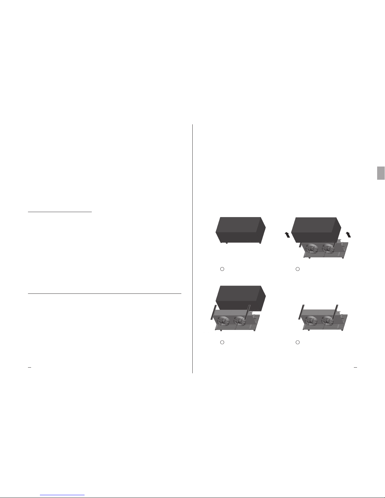
Please nd below the unpacking procedure:
TKSmart as shipped
Remove the 4 screws
Remove the carton box
Please read the documentation attached for
more information
1
3
2
4
09
TC 3.6
Each product is supplied with EC Declaration of Incorporation
TC 3.7
Additional product documentation, consisting of catalogues, guides and technical bulletins, is provided directly
by ThermoKey and is available on the website www.thermokey.com.
CATALOGUES – http://www.thermokey.com/Cataloghi.aspx
MANUALS – http://www.thermokey.com/Manuali.aspx
TC 4. Intended use
TC 4.1
The model must be used exclusively for the purpose indicated below, otherwise its use is considered improper and
exempts the manufacturer from any responsibility.
TC 4.2
TKSmart series microchannel condensers are used as condensers in HVAC&R applications. The product is not
provided with a dedicated subcooling circuit. The thermodynamic performances are defined in accordance with
EN 327.
TC 4.3
The standard model is equipped with electrical fans not suitable to withstand additional static pressures.
TC 4.4
If in doubt regarding the intended use of the product, please contact the Manufacturer.
TC 5. Inspection, handling and transport
TC 5.1
Upon receipt of the product, check the integrity of the packaging and of the product; immediately notify any damage
to the carrier. The packaging is manufactured in accordance with the model, the appropriate means of transport and
the correct handling.
TC 5.2
During transport and handling of the packed product, avoid any excessive and improper stress on the package.
TC 5.3
During transport and handling of the packed product, use appropriate protection to avoid any injury caused by
packaging parts such as nails, boards or cardboards and parts of the product such as fins or casing parts
(see DPI Technical Manual Section I chapter IG 6).

Heat Exchange SolutionsThermoKey Technical Manual TC Instruction and technical data
1211
EN
MT TC R MC EN 04 2017MT TC R MC EN 04 2017
TC 7.2
The product mainly consists of a finned heat exchanger with microchannel technology, structural frame in aluminium
metal sheets and electric fans.
TC 7.3
Periodically check the fixing points of the model, electrical connections and connections to the refrigerant line.
TC 7.4
Provide for periodic cleaning of the casing and the heat exchanger using suitable detergents or possibly water and soap
with a neutral pH. Do not use harsh detergents, solvents, acidic or basic solutions containing mainly copper, chlorine
or ammonia. Avoid the use of abrasives in general. If the use of sanitising products is required, check their compatibility
with the materials. If in doubt, contact the Manufacturer, requiring the specification “how to use microchannel cores”.
TC 7.5
Inspection and maintenance intervals depend on the type of plant, therefore are to be defined by experienced and
qualified personnel.
TC 7.6
For any operation on the product not described in this manual, please contact the Manufacturer.
TC 7.7
Avoid carrying out on/off settings both on the air and the refrigerant side, if the air temperature is lower than -10 °C
in order to avoid thermal shocks.
TC 7.8
The electric fans are equipped with a load-bearing protective grille to allow any replacement operations to be done
completely from the outside.
TC 8. Wiring diagrams of fans
TC 8.1
The frame of each model is equipped with a ground terminal (PE) with an identification tag. It is mandatory to
connect the ground terminal of the unit to the plant or to the external conductor of the earthing system.
TC 8.2
In models with wired electrical fans it is mandatory to connect the protection conductors of the electrical fans to the
plant or to the external conductor of the earthing system.
TC 8.3
It is mandatory to use protection systems against electric shock and protection of the equipment on the power lines
of the electrical fans. The fan assemblies are equipped with thermal contacts, normally closed, inserted in the motor
windings. Connect the thermal contacts to protect the motor from overheating.
Warning: over-temperature may not directly arise from an over-current. Please be aware that the temperature switch
closes again itself when the temperature decreases without a manual reset.
TC 6.1
The installation and commissioning of the product must be performed by qualified and experienced personnel.
TC 6.2
Check that the support structures and anchoring devices comply with the weight and shape of the product (see chapter
Dimensions and Technical Data).
TC 6.3
Fix the unit to all points provided (see chapter Dimensions) with adequate anchors and in accordance with the total weight
(net weight of the product, weight of the refrigerant, weight of the heat exchanger, weight of any ice accumulation).
TC 6.4
The product is not designed to support additional loads.
TC 6.5
Check that the electrical supply complies with the specifications as indicated on the technical data label.
TC 6.6
Before connecting the product, verify the presence of shut-off and sectioning devices on the power supply line,
protection against electric shock, protection of equipment and anything else required by law.
TC 6.7
If speed controllers are used for the electric fan, verify their compatibility. Non-compliant devices may generate noise
and may damage the motors; the Manufacturer does not guarantee the rated performance for models equipped with
speed controllers.
TC 6.8
Check that the operating condition limits (humidity, temperatures and pressure) meet the specific requirements of
the product selection.
TC 6.9
Access to the installed unit, for any type of intervention, must be reserved to experienced personnel qualied to run the
system, according to current regulations.
TC 6. Installation and commissioning
TC 7. General maintenance and control
TC 7.1
Before performing any maintenance work, make sure that the power supply line of the product has been sectioned:
the electrical parts may be connected to automatic controls. All maintenance work should be performed by
qualified and experienced personnel.
Heat Exchange SolutionsThermoKey Technical Manual TC Instruction and technical data
1413
EN
MT TC R MC EN 04 2017MT TC R MC EN 04 2017
TMCH1150HLLD
TMCH1150HLLY
TMCH1150HLLM
Model
TMCH1250HLLD
TMCH1250HLLY
TMCH1250HLLM
TMCH1350HLLD
TMCH1350HLLY
TMCH1350HLLM
Wei ght 38,5 kg
Volume 1,6 dm³
Connection
IN 1 x 22 mm
OUT 1 x 22 mm
Wei ght 72 kg
Volume 2,4 dm³
IN 1 x 22 mm
OUT 1 x 22 mm
Wei ght 105,5 kg
Volume 3,2 dm³
IN 1 x 28 mm
OUT 1 x 28 mm
W
L
H
Size horizontal air flow
W
H
L
780 mm
644 mm
1067 mm
W
H
L
780 mm
644 mm
1817 mm
W
H
L
780 mm
644 mm
2567 mm
W
L
H
W
H
L
674 mm
911 mm
1067 mm
W
H
L
674 mm
911 mm
1817 mm
W
H
L
674 mm
911 mm
2567 mm
Size vertical air flow
Scale 1:20
TMCH1150HUUD
TMCH1150HUUY
TMCH1150HUUM
Model
TMCH1250HUUD
TMCH1250HUUY
TMCH1250HUUM
Wei ght 56 kg
Volume 2,8 dm³
Wei ght 96 kg
Volume 4,4 dm³
W
H
L
973 mm
1006 mm
1347 mm
W
L
H
W
L
H
IN 1 x 28 mm
OUT 1 x 28 mm
Scale 1:20
W
H
L
Size horizontal air flow
875 mm
943 mm
1347 mm
W
H
L
875 mm
943 mm
2347 mm
Connection
IN 1 x 22 mm
OUT 1 x 22 mm
Size vertical air flow
W
H
L
973 mm
1006 mm
2347 mm
Scale 1:20
W
L
H
W
L
H
TMCH1163HUUD
TMCH1163HUUY
Model
TMCH1263HUUD
TMCH1263HUUY
Wei ght 63 kg
Volume 2,8 dm³
Wei ght 110 kg
Volume 4,4 dm³
Connection
IN 1 x 28 mm
OUT 1 x 28 mm
IN 1 x 28 mm
OUT 1 x 28 mm
W
H
L
W
H
L
875 mm
943 mm
1347 mm
W
H
L
W
H
L
875 mm
943 mm
2347 mm
973 mm
993 mm
1347 mm
973 mm
993 mm
2347 mm
Size horizontal air flow Size vertical air flow
1X500 LL – 2X500 LL – 3X500 LL
1X500 UU – 2X500 UU
1X630 UU – 2X630 UU
TC 8.4
Strictly follow the wiring diagrams in order to avoid damage to the motors (a, b, c.....)
TC 8.5
For models fitted with non-standard electrical fans, please refer to the wiring diagrams and consumption indicated in
the supplementary sheets and on the rating plate.
TC 8.6
Before using speed regulation systems for the electrical fans, check their compatibility, non-compatible controllers may
generate noise and may damage the fans; the Manufacturer does not take any responsibility regarding the performance
of the products equipped with control systems unless they are dened in the oer.
Electrical values of standard fans:
For other versions of fans, please contact ThermoKey.
Rpm: 1430 rpm
Power: 160 W
Current: 0,73 A
Rpm: 1340/1060 rpm
Power: 710/480 W
Current: 1,4/0,8 A
Rpm: 1300 rpm
Power: 680 W
Current: 3,0 A
Rpm: 1340/1070 rpm
Power: 1900/1350 W
Current: 3,2/2,2 A
Diameter: 400 (M)
Nominal voltage: 230 V
Frequency: 50 H
Diameter: 500 (D/Y)
Nominal voltage: 400 V
Frequency: 50 H
Diameter: 500 (M)
Nominal voltage: 230 V
Frequency: 50 H
Diameter: 630 (D/Y)
Nominal voltage: 400 V
Frequency: 50 H
W
L
H
W
L
H
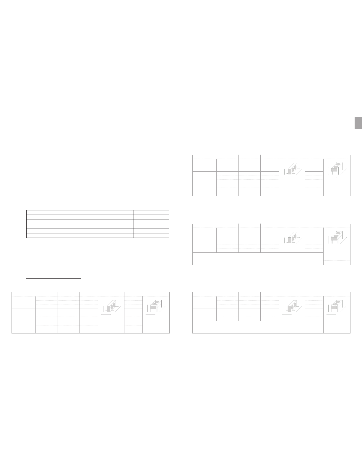
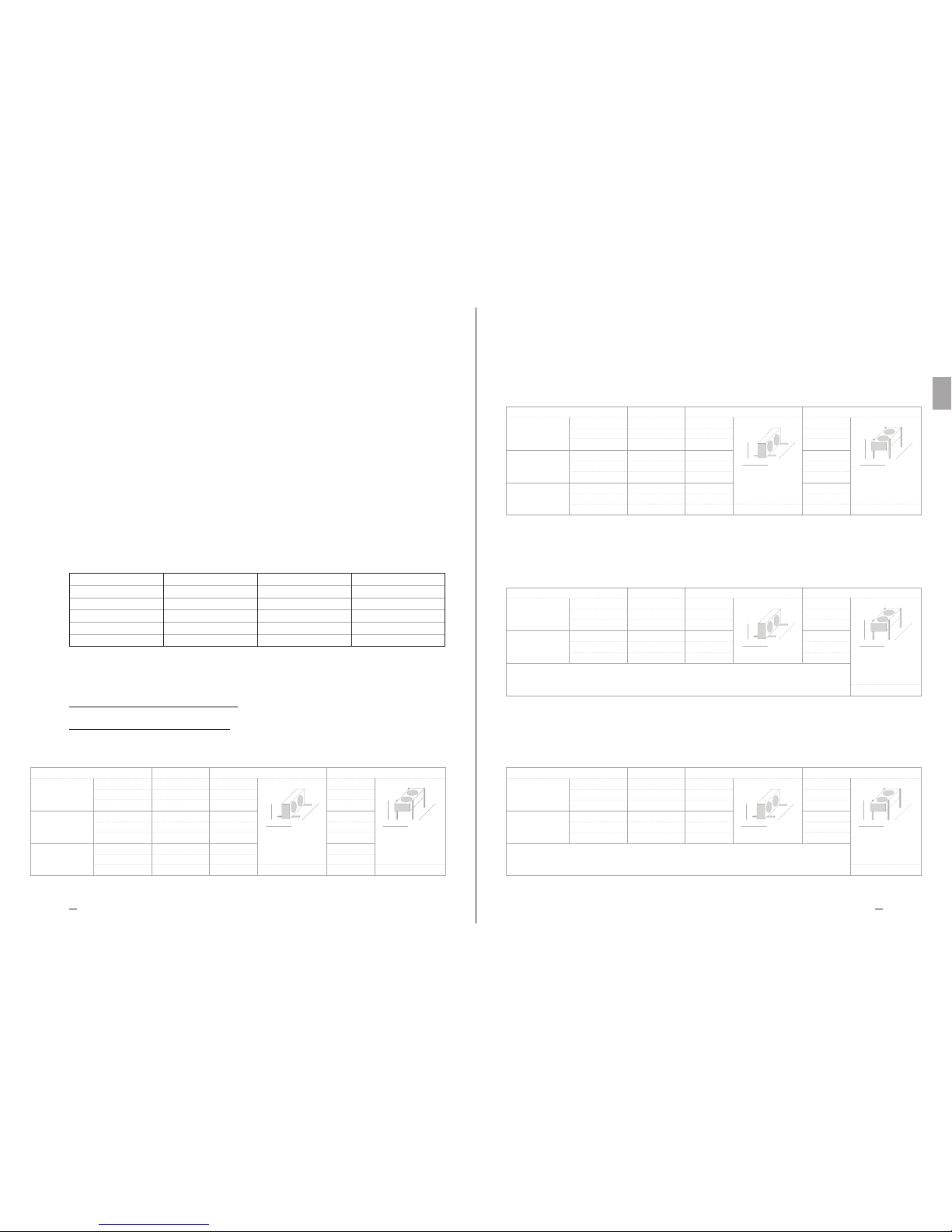
TMCH1140HLLM
TMCH1240HLLM
TMCH1340HLLM
Wei ght 35 kg
Volume 1,6 dm³
Wei ght 65 kg
Volume 2,4 dm³
Wei ght 95 kg
Volume 3,2 dm³
Connection
IN 1 x 22 mm
OUT 1 x 22 mm
IN 1 x 22 mm
OUT 1 x 22 mm
IN 1 x 28 mm
OUT 1 x 28 mm
Model
W
H
L
Size horizontal air flow
780 mm
644 mm
1067 mm
W
H
L
780 mm
644 mm
1817 mm
W
H
L
780 mm
644 mm
2567 mm
W
H
L
Size vertical air flow
674 mm
879 mm
1067 mm
W
H
L
674 mm
879 mm
1817 mm
W
H
L
674 mm
879 mm
2567 mm
Scale 1:20
TC 9. Dimensions
— Technical Data
1X400 LL – 2X400 LL – 3X400 LL
Manuale tecnico TC
Serie TMC
Condensatori commerciali TKSmart
LA VERSIONE ORIGINALE DELLE PRESENTI ISTRUZIONI
È IN LINGUA ITALIANA
MT TC R MC IT 04 2017
IT

Manuale Tecnico TC Istruzioni e dati tecnici
1716
Heat Exchange SolutionsThermoKey
IT
MT TC R MC IT 04 2017 MT TC R MC IT 04 2017
LEGGERE ATTENTAMENTE E COMPRENDERE COMPLETAMENTE TUTTE
LE INFORMAZIONI CONTENUTE IN QUESTE ISTRUZIONI PRIMA DELLA
PROGETTAZIONE ED IN OGNI CASO PRIMA DI EFFETTUARE QUALUNQUE
OPERAZIONE DI MOVIMENTAZIONE, DISIMBALLAGGIO, MONTAGGIO,
POSIZIONAMENTO E MESSA IN ESERCIZIO DELL’APPARECCHIO.
THERMOKEY DECLINA OGNI RESPONSABILITÀ PER DANNI A PERSONE
O COSE DERIVANTI DALLA MANCATA OSSERVANZA DELLE INDICAZIONI
CONTENUTE NEL PRESENTE DOCUMENTO.
L’originale del presente manuale è in italiano , ed è reperibile sul sito internet: www.thermokey.com.
La traduzione in inglese è conforme all’originale ed è reperibile sul sito internet: www.thermokey.com.
Le traduzioni in altre lingue possono contenere errori; in caso di dubbio fare sempre riferimento
alla versione originale in italiano od alla sua traduzione in inglese.
Il sistema di gestione Qualità della ThermoKey è certificato in conformità alla norma ISO 9001,
il Sistema di Gestione Ambiente è certificato in conformità alla norma ISO 14001 e il Sistema di
Gestione Sicurezza è certificato in conformità alla norma OHSAS 18001.
Manuale Tecnico TC Istruzioni e dati tecnici
1918
Heat Exchange SolutionsThermoKey
IT
MT TC R MC IT 04 2017 MT TC R MC IT 04 2017
TC 1. Riferimenti Normativi
Il prodotto descritto in questo manuale risulta conforme alla:
DIRETTIVA MACCHINE 2006/42/EC
DIRETTIVA BASSA TENSIONE 2006/95/EC
DIRETTIVA COMPATIBILITA' ELETTROMAGNETICA 2004/108/EC
DIRETTIVA PED 97/23/EC (DAL 19/07/2016 2014/68/UE)
DIRETTIVA ErP 2009/125/EC
Pericolo di elettrocuzione. Il prodotto è allestito con elettroventilatori con tensione nominale di funzionamento di 400V
AC trifase o 230V monofase. Le linee di alimentazione elettrica dovranno utilizzare i sistemi di protezione contro la scossa
elettrica e di protezione dell’equipaggiamento previsti dalla normativa vigente.
Pericolo di taglio. Lo scambiatore di calore, parte integrante del prodotto, è costituito da alette metalliche con bordi taglienti, non
protette. La carrozzeria è costituita da componenti in lamiera che in alcuni punti possono presentare bordi taglienti non protetti.
Pericolo parti in movimento. Il prodotto è allestito con elettroventilatori dotati di griglia di protezione secondo
quanto previsto dalla normativa vigente. Per alcuni prodotti potrebbe essere possibile accedere volutamente alle parti
in movimento (pale dei motoventilatori) da zone non protette. Prima di qualsiasi accesso assicurarsi che le parti
in movimento non possano costituire pericolo agli operatori.
Pericolo di schiacciamento degli arti o della persona. Durante le fasi di movimentazione, trasporto ed installazione,
funzionamento e manutenzione, porre la massima attenzione al peso indicato di ogni prodotto per evitare ribaltamenti
o cadute pericolose verso gli operatori.
TC 2. Pericoli
TC 3. Avvertenze
TC 3.1
Contenuto del Manuale Tecnico di prodotto:
ISTRUZIONI GENERALI PER UN USO SICURO (IG)
ISTRUZIONI PER LA MOVIMENTAZIONE ED IL DISIMBALLO (IM)
ISTRUZIONI E DATI TECNICI (TC)
ISTRUZIONI SPECIFICHE D’USO E MANUTENZIONE (IS)
TC 3.2
Questo manuale è la sezione TC denominata ISTRUZIONI E DATI TECNICI del Manu ale Tecnico di prodotto.
Per qualsiasi informazione non contemplata nel presente manuale fare riferimento alle altre sezioni (IG, IM, IS) e in
caso di dubbio contattare ThermoKey.
TC 3.3
Questo manuale è parte integrante dei modelli TMC e come tale deve essere conservarto per tutto il periodo di vita del prodotto.
TC 3.4
Eventuale documentazione tecnica supplementare relativa ai prodotti non standard è allegata al presente manuale,
è integrante ed è codificata con codice specifico indicato sui documenti di spedizione.
TC 3.5
Il prodotto descritto in questo manuale è considerato una quasi-macchina quindi non utilizzabile così come fornito
ma è un componente per impianti di condizionamento o refrigerazione e deve essere installato e messo in servizio solo
da operatori qualificati (vedere capitolo relativo ad installazione e messa in opera).
TC 1. RIFERIMENTI NORMATIVI
TC 2. PERICOLI
TC 3. AVVERTENZE
TC 4. DESTINAZIONE D’USO
TC 5. ISPEZIONE, MOVIMENTAZIONE E TRASPORTO
TC 6. INSTALLAZIONE E MESSA IN OPERA
TC 7. MANUTENZIONE GENERALE E CONTROLLO
TC 8. SCHEMI DI COLLEGAMENTO DEI MOTOVENTILATORI
TC 9. CARATTERISTICHE DIMENSIALI – DATI TECNICI
INDICE
18
19
19
20
20
22
22
23
24

Manuale Tecnico TC Istruzioni e dati tecnici
2120
Heat Exchange SolutionsThermoKey
IT
MT TC R MC IT 04 2017 MT TC R MC IT 04 2017
TC 3.6
Ogni prodotto è corredato di Dichiarazione di Incorporazione CE.
TC 3.7
Ulteriore documentazione relativa al prodotto, costituita da cataloghi, guide e bollettini tecnici, è fornita
direttamente dal Costruttore reperibile sul sito internet www.thermokey.com.
CATALO GHI – http://www.thermokey.com/Cataloghi.aspx
MANUALI – http://www.thermokey.com/Manuali.aspx
TC 4. Destinazione d'uso
TC 4.1
Il modello deve essere utilizzato esclusivamente per lo scopo di seguito indicato altrimenti, l’uso è da considerarsi
improprio ed esonera ThermoKey da qualsiasi responsabilità conseguente.
TC 4.2
I condensatori a microcanali della serie TKSmart sono utilizzati come condensatori in applicazioni HVAC&R.
Non è provvisto di un circuito dedicato di sottoraffreddamento. Le prestazione termodinamiche sono definite
secondo la EN 327.
TC 4.3
Il modello standard è equipaggiato con motoventilatori non adatti a sopportare prevalenze statiche aggiuntive.
TC 4.4
In caso di dubbio sulla destinazione d'uso contattare ThermoKey.
TC 5. Ispezione, movimentazione e trasporto
TC 5.1
Al ricevimento del modello controllare lo stato di integrità dell'imballaggio e del prodotto; contestare subito al
trasportatore qualsiasi danno eventuale verificatosi. L’imballaggio è fabbricato conformemente al modello, agli
adeguati mezzi di trasporto e di movimentazione.
TC 5.2
Durante il trasporto e la movimentazione del modello nel suo imballaggio, evitare sollecitazioni non conformi e
improprie sul prodotto imballato.
TC 5.3
Durante il trasporto e la movimentazione del prodotto imballato, utilizzare apposite protezioni per evitare di ferirsi
con le parti dell’imballaggio come chiodi, tavole o cartone e le parti del modello come le alette o la carrozzeria (vedi
DPI manuale tecnico sezione I cap IG 6).
TC 5.4
Disimballare il modello il più vicino possibile al luogo di installazione (vedi anche installazione e messa in opera).
In generale il modello non deve essere trasportato o movimentato privo dell’imballaggio originale.
TC 5.5
Durante la movimentazione per l'installazione del modello disimballato, utilizzare apposite protezioni per evitare di ferirsi
con le parti taglienti come le alette o la carrozzeria (vedi DPI manuale tecnico sezione I cap IG6).
Si riportano di seguito le operazioni di disimballo:
TKSmart imballato
Rimuovere le 4 viti
Rimuovere l’imballo in cartone
Per cortesia leggere la documentazione
allegata per maggiori informazioni
1
3
2
4

Manuale Tecnico TC Istruzioni e dati tecnici
2322
Heat Exchange SolutionsThermoKey
IT
MT TC R MC IT 04 2017 MT TC R MC IT 04 2017
TC 6.1
L’installazione e la messa in opera del modello deve essere eseguita da personale esperto e qualificato.
TC 6.2
Verificare che le strutture di supporto e gli ancoraggi siano conformi al peso ed alla forma del modello (vedi capitoli
Caratteristiche Dimensionali e Dati Tecnici).
TC 6.3
Fissare il modello a tutti i punti previsti (vedi capitolo Caratteristiche Dimensionali) con ancoraggi adeguati e conformi al
peso complessivo (peso netto del modello, peso del refrigerante, peso dell’eventuale accumulo di neve sullo scambiatore).
TC 6.4
Il modello non è progettato per supportare carichi aggiuntivi.
TC 6.5
Verificare che la linea di alimentazione elettrica sia conforme alle caratteristiche del modello indicate sui dati di targa.
TC 6.6
Prima di collegare il modello verificare che siano stati utilizzati i dispositivi di sezionamento ed interruzione dalla rete
di alimentazione, di protezione contro la scossa elettrica, di protezione dell’equipaggiamento e quant’altro previsto
dalla normativa vigente.
TC 6.7
Se venissero utilizzati dispositivi di regolazione del numero di giri dei motoventilatori verificarne la compatibilità,
dispositivi non compatibili possono generare rumorosità e danneggiamenti ai motoventilatori; ThermoKey non
garantisce le prestazioni indicate per modelli equipaggiati con dispositivi di regolazione.
TC 6.8
Verificare che i limiti di funzionamento (umidità, temperature e pressioni) siano conformi alle caratteristiche di
selezione del prodotto.
TC 6.9
L’accessibilità al modello installato, per qualsiasi tipo di intervento, deve essere riservata a personale esperto e
qualificato alla conduzione dell’impianto, secondo le norme vigenti.
TC 6. Installazione e messa in opera
TC 7. Manutenzione generale e controllo
TC 7.1
Prima di effettuare qualsiasi intervento di manutenzione accertarsi che l’alimentazione elettrica del modello
sia stata sezionata: le parti elettriche potrebbero essere collegate a controlli automatici. Tutte le operazioni di
manutenzione devono essere effettuate da personale esperto e qualificato.
TC 7.2
Il modello è costituito principalmente da: uno scambiatore di calore a pacco alettato con tecnologia a microcanale,
una carrozzeria portante in lamiera di alluminio e da elettroventilatori.
TC 7.3
Verificare periodicamente i fissaggi del modello, le connessioni elettriche e i collegamenti alla linea del refrigerante.
TC 7.4
Provvedere alla pulizia periodica della carrozzeria e dello scambiatore utilizzando detergenti idonei o eventualmente
dell’acqua e sapone con pH neutro. Non utilizzare detergent i aggressivi, solventi, soluzioni acide o basiche e contenenti
principalmente rame, cloro o ammoniaca. Evitare l’utilizzo di abrasivi in genere. Se si dovessero utilizzare igienizzanti
verificarne la compatibilità con i materiali. In caso di dubbio cont attare ThermoKey, richiedendo la specifica “how to
use microchannel cores”.
TC 7.5
I periodi di verifica e manutenzione sono dipendenti dalla tipologia di impianto, pertanto da definirsi da personale
esperto e qualificato.
TC 7.6
Per qualsiasi operazione sul modello, non descritta su questo manu ale, contattare ThermoKey.
TC 7.7
Evitare di fare regolazioni on/off sia lato refrigerante che aria, qualora la temperatura dell’aria sia inferiore a -10°C.
TC 7.8
I motoventilatori sono dotati di griglia di protezione portante per permettere le eventuali operazioni di sostituzione
completamente dall’esterno.
TC 8. Schemi di collegamento
dei motoventilatori
TC 8.1
Il telaio di ogni modello è dotato di un polo di terra (PE) con etichetta di identificazione. E’ obbligatorio collegare il
polo di terra del modello all’impianto o al conduttore esterno di messa a terra.
TC 8.2
Nei modelli con motoventilatori cablati è obbligatorio collegare i conduttori di protezione dei motoventilatori
all’impianto o al conduttore esterno di messa a terra.
TC 8.3
È obbligatorio utilizzare i sistemi di protezione contro la scossa elettrica e di protezione dell’equipaggiamento sulle
linee di alimentazione dei motoventilatori. I motoventilatori sono dotati di termocontatti normalmente chiusi inseriti
negli avvolgimenti del motore. Collegare i termocontatti per proteggere il motore dalle sovratemperature.

Manuale Tecnico TC Istruzioni e dati tecnici
2524
Heat Exchange SolutionsThermoKey
IT
MT TC R MC IT 04 2017 MT TC R MC IT 04 2017
Attenzione che una sovratemperatura può non essere direttamente dipendente da una sovracorrente. Attenzione che
il termocontatto richiude al riabassarsi della temperatura senza un ripristino manuale.
TC 8.4
Seguire rigorosamente gli schemi elettrici riportati per evitare il danneggiamento dei motori (a,b,c.....).
TC 8.5
Per modelli che montano motoventilatori non standard fare riferimento agli schemi ed assorbiment i indicati nei fogli
supplementari e nei dati di targa.
TC 8.6
Prima di utilizzare sistemi di regolazione del numero di giri dei motoventilatori vericarne la compatibilità, regolatori non
compatibili possono generare rumorosità e danneggiamenti ai motoventilatori; ermoKey non si assume responsabilità
alcuna sulle prestazioni dei modelli equipaggiati con sistemi di regolazione se non deniti in fase di oerta.
Si riportano i valori elettrici dei ventilatori standard:
Per altre versioni di ventilatori, contattare ThermoKey.
Nr. giri: 1430 rpm
Potenza: 160 W
Corrente: 0,73 A
Nr. giri: 1340/1060 rpm
Potenza: 710/480 W
Corrente: 1,4/0,8 A
Nr. giri: 1300 rpm
Potenza: 680 W
Corrente: 3,0 A
Nr. giri: 1340/1070 rpm
Potenza: 1900/1350 W
Corrente: 3,2/2,2 A
Diametro: 400 (M)
Tensione nominale: 230 V
Frequenza: 50 H
Diametro: 500 (D/Y)
Tensione nominale: 400 V
Frequenza: 50 H
Diametro: 500 (M)
Tensione nominale: 230 V
Frequenza: 50 H
Diametro: 630 (D/Y)
Tensione nominale: 400 V
Frequenza: 50 H
W
L
H
W
L
H
TMCH1140HLLM
TMCH1240HLLM
TMCH1340HLLM
Wei ght 35 kg
Volume 1,6 dm³
Wei ght 65 kg
Volume 2,4 dm³
Wei ght 95 kg
Volume 3,2 dm³
Connection
IN 1 x 22 mm
OUT 1 x 22 mm
IN 1 x 22 mm
OUT 1 x 22 mm
IN 1 x 28 mm
OUT 1 x 28 mm
Model
W
H
L
Size horizontal air flow
780 mm
644 mm
1067 mm
W
H
L
780 mm
644 mm
1817 mm
W
H
L
780 mm
644 mm
2567 mm
W
H
L
Size vertical air flow
674 mm
879 mm
1067 mm
W
H
L
674 mm
879 mm
1817 mm
W
H
L
674 mm
879 mm
2567 mm
Scale 1:20
TC 9. Caratteristiche dimensionali
— Dati tecnici
1X400 LL – 2X400 LL – 3X400 LL
TMCH1150HLLD
TMCH1150HLLY
TMCH1150HLLM
Model
TMCH1250HLLD
TMCH1250HLLY
TMCH1250HLLM
TMCH1350HLLD
TMCH1350HLLY
TMCH1350HLLM
Wei ght 38,5 kg
Volume 1,6 dm³
Connection
IN 1 x 22 mm
OUT 1 x 22 mm
Wei ght 72 kg
Volume 2,4 dm³
IN 1 x 22 mm
OUT 1 x 22 mm
Wei ght 105,5 kg
Volume 3,2 dm³
IN 1 x 28 mm
OUT 1 x 28 mm
W
L
H
Size horizontal air flow
W
H
L
780 mm
644 mm
1067 mm
W
H
L
780 mm
644 mm
1817 mm
W
H
L
780 mm
644 mm
2567 mm
W
L
H
W
H
L
674 mm
911 mm
1067 mm
W
H
L
674 mm
911 mm
1817 mm
W
H
L
674 mm
911 mm
2567 mm
Size vertical air flow
Scale 1:20
TMCH1150HUUD
TMCH1150HUUY
TMCH1150HUUM
Model
TMCH1250HUUD
TMCH1250HUUY
TMCH1250HUUM
Wei ght 56 kg
Volume 2,8 dm³
Wei ght 96 kg
Volume 4,4 dm³
W
H
L
973 mm
1006 mm
1347 mm
W
L
H
W
L
H
IN 1 x 28 mm
OUT 1 x 28 mm
Scale 1:20
W
H
L
Size horizontal air flow
875 mm
943 mm
1347 mm
W
H
L
875 mm
943 mm
2347 mm
Connection
IN 1 x 22 mm
OUT 1 x 22 mm
Size vertical air flow
W
H
L
973 mm
1006 mm
2347 mm
Scale 1:20
W
L
H
W
L
H
TMCH1163HUUD
TMCH1163HUUY
Model
TMCH1263HUUD
TMCH1263HUUY
Wei ght 63 kg
Volume 2,8 dm³
Wei ght 110 kg
Volume 4,4 dm³
Connection
IN 1 x 28 mm
OUT 1 x 28 mm
IN 1 x 28 mm
OUT 1 x 28 mm
W
H
L
W
H
L
875 mm
943 mm
1347 mm
W
H
L
W
H
L
875 mm
943 mm
2347 mm
973 mm
993 mm
1347 mm
973 mm
993 mm
2347 mm
Size horizontal air flow Size vertical air flow
1X500 LL – 2X500 LL – 3X500 LL
1X500 UU – 2X500 UU
1X630 UU – 2X630 UU

Technisches Handbuch - Tc
Serie TMC
Gewerbe-Verflüssiger TKSmart
MT TC R MC DE 04 2017
DE

2827
Heat Exchange SolutionsThermoKey
DE
MT TC R MC DE 04 2017MT TC R MC DE 04 2017
Anweisungen und Technische SpezifikationenTechnisches Handbuch - TC
LESEN SIE ALLE INFORMATIONEN DIESER ANWEISUNGEN AUFMERKSAM
DURCH BEVOR SIE PLANEN UND IN JEDEM FALL VOR JEGLICHER
HANDHABUNG, DEM AUSPACKEN, DER MONTAGE, DER INSTALLATION
UND INBETRIEBNAHME DES GERÄTES. DER HERSTELLER ÜBERNIMMT
KEINE HAFTUNG FÜR SCHÄDEN AN PERSONEN ODER GEGENSTÄNDEN,
DIE DURCH MISSACHTUNG DER IN DIESEM DOKUMENT ENTHALTENEN
ANWEISUNGEN ENTSTANDEN SIND.
Die Originalsprache dieses Handbuchs ist Italienisch, erhältlich auf der Website:
www.thermokey.com.
Die englische Übersetzung ist eine originalgetreue Kopie des Originaldokuments und auf der
Website erhältlich: www.thermokey.com.
Anderssprachige Übersetzungen können Fehler enthalten; im Zweifelsfall immer in der
ursprünglichen italienischen Version oder der englischen Übersetzung nachschlagen.
Das ThermoKey SPA Qualitätsmanagementsystem ist zertifiziert nach ISO 9001, das
ThermoKey SPA Umweltmanagement ist zertifiziert nach ISO 14001 und das ThermoKey
Sicherheitsmanagementsystem ist zertifiziert nach OHSAS 18001.
3029
Heat Exchange SolutionsThermoKey
DE
MT TC R MC DE 04 2017MT TC R MC DE 04 2017
Gefahr eines Stromschlags. Das Produkt ist mit Ventilatoren mit einer Nennspannung von 400 V AC Einphasen-Betrieb
oder 230 V Drei-Phasen-Betrieb ausgestattet. Die elektrischen Stromversorgungsleitungen müssen gesetzlich vorgeschriebene
Schutzvorrichtungen gegen Stromschlag und für den Geräteschutz aufweisen.
Schnittgefahr. Der Wärmetauscher, integraler Bestandteil des Produkts, enthält Metallamellen mit ungeschützten
scharfen Kanten. Das Gehäuse besteht aus Metallkomponenten, die ungeschützte scharfe Kanten aufweisen können.
Gefahr durch bewegliche Teile. Das Produkt ist mit elektrischen Ventilator-Motoren ausgestattet, die über ein gesetzlich
vorgeschriebenes Schutzgitter verfügen. Bei einigen Produkten ist es möglich, von nicht geschützten Bereichen gezielt
auf bewegliche Teile (Ventilator-Motorklingen) zuzugreifen. Vor jedem Zugriff darauf achten, dass die beweglichen Teile
keine Gefahr für die Bediener darstellen.
Quetschungsgefahr für Gliedmaßen oder Personen. Während der Handhabung, des Transports und der Montage,
des Betriebs und der Wartung genau auf das jeweils angegebene Gewicht jedes Produkts achten, um ein Umkippen oder
gefährliches Herabfallen auf die Bediener zu verhindern.
TC 2. Gefahren
TC 3. Warnhinweise
TC 3.1
Inhalt des technischen Produkt-Handbuchs:
ALLGEMEINE SICHERHEITSHINWEISE (IG)
ANWEISUNGEN FÜR DIE HANDHABUNG UND DAS AUSPACKEN (IM)
ANWEISUNGEN UND TECHNISCHE DATEN (IT)
BESONDERE HINWEISE FÜR GEBRAUCH UND PFLEGE (IS)
TC 3.2
Diese Anleitung entspricht Abschnitt TC, mit dem Titel ANWEISUNGEN UND TECHNISCHE DATEN des technischen
Produkt-Handbuchs. Für alle Informationen, die nicht in diesem Handbuch behandelt werden, in den anderen Abschnitten
(IG-IM-IS) nachschlagen und sich im Zweifelsfall an den Hersteller wenden.
TC 3.3
Dieses Handbuch ist integraler Bestandteil der Modelle TMC und als solches muss es für die gesamte Betriebsdauer des
Produkts auewahrt werden.
TC 3.4
Jegliche zusätzliche technische Dokumentation bezüglich von Nicht-Standard-Produkten ist dieser Anleitung beigelegt und
als deren integraler Bestandteil zu betrachten, weshalb sie mit einem spezischen Code in den Frachtpapieren identiziert ist.
TC 3.5
Das in diesem Handbuch beschriebene Produkt ist nicht als einzelständiges Gerät zu betrachten sondern es ist Teil einer
Klima- und Kälteanlage. Es muss daher von qualizierten Technikern installiert und in B etrieb genommen werden (siehe
Kapitel Installation und Inbetriebnahme).
Anweisungen und Technische SpezifikationenTechnisches Handbuch - TC
TC 1. Normen und Richtlinien
Das in diesem Handbuch beschriebene Gerät entspricht:
MASCHINENRICHTLINIE 2006/42/EG
NIEDERSPANNUNGS-RICHTLINIE 2006/95/EG
ELEKTROMAGNETISCHE VERTRÄGLICHKEITSRICHTLINIE 2004/108/EG
DGRL-RICHTLINIE 97/23/EG
ÖKODESIGN-RICHTLINIE 2009/125/EG
TC 1. NORMEN UND RICHTLINIEN
TC 2. GEFAHREN
TC 3. WARNHINWEISE
TC 4. VERWENDUNGSZWECK
TC 5. KONTROLLE, HANDHABUNG UND TRANSPORT
TC 6. MONTAGE UND INBETRIEBNAHME
TC 7. ALLGEMEINE WARTUNG UND KONTROLLE
TC 8. VERDRAHTUNGSSCHEMATA FÜR DIE VENTILATOREN
TC 9. ABMESSUNGEN - TECHNISCHE DATEN
INHALTSVERZEICHNIS
29
30
30
31
31
33
33
34
35

3231
Heat Exchange SolutionsThermoKey
DE
MT TC R MC DE 04 2017MT TC R MC DE 04 2017
TC 5.4
Das Gerät so nah wie möglich am Montageort auspacken (siehe auch Kapitel Installation und Inbetriebnahme).
Generell sollte das Gerät nicht ohne die Originalverpackung transportiert oder gehandhabt werden.
TC 5.5
Bei der Handhabung der entpackten Montage-Einheit entsprechende Schutzkleidung verwenden, um Verletzungen durch
scharfe Kanten wie Lamellen oder Gehäuseteile (siehe DPI Technisches Handbuch Abschnitt I Kapitel IG6) zu vermeiden.
Nachfolgend werden die einzelnen Auspack-Schritte beschrieben:
TKSmart, wie geliefert
Die 4 Schrauben lösen
Den Karton entfernen
Für weitere Informationen bitte die
beiliegende Dokumentation lesen
1
3
2
4
Anweisungen und Technische SpezifikationenTechnisches Handbuch - TC
TC 3.6
Jedes Produkt wird mit EG-Einbauerklärung geliefert.
TC 3.7
Die zusätzliche Produktdokumentation, die aus Katalogen, Anleitungen und technischen Bulletins besteht, wird direkt
von ermoKey zur Verfügung gestellt und ist auf unserer Website einsehbar www.thermokey.com.
KATALOGE – http://ww w.thermokey.com/Cataloghi.aspx
HANDBÜCHER – http://www.thermokey.com/Manuali.aspx
TC 4. Verwendungszweck
TC 4.1
Das Gerät sollte ausschließlich für den nachstehend angegebenen Zweck verwendet werden, da dessen anderweitige
Verwendung als unsachgemäß betrachtet wird und den Hersteller von jeglicher Haftung entbindet.
TC 4.2
Die Mikrokanal-Verflüssiger der TKSmart Serie werden als Kondensatoren im HLK-Bereich eingesetzt. Sie
verfügen nicht über einen getrennten Unterkühlungskreislauf. Die thermodynamischen Leistungen sind gemäß
EN 327 bestimmt.
TC 4.3
Das Standardmodell ist mit Motorventilatoren ausgestattet, die nicht dazu geeignet sind, zusätzlichem, statischem
Druck standzuhalten.
TC 4.4
Im Zweifelsfall bezüglich des Verwendungszwecks bitte beim Hersteller nachfragen.
TC 5. Kontrolle, Handhabung und Transport
TC 5.1
Nach Erhalt des Geräts die Unversehrtheit der Verpackung und des Produkts überprüfen; den Transporteur
unverzüglich über mögliche Schäden informieren. Die Ver packung ist der entsprechenden Einheit und gemäß den
Beförderungs- und Transportmitteln ausgelegt.
TC 5.2
Während des Transports und der Handhabung des Geräts ist eine unsachgemäße Beanspruchung der Ver packung zu
vermeiden.
TC 5.3
Während des Transports und der Handhabung des verpackten Produkts auf angemessenen Schutz achten, um
Verletzungen von Verpackungsteilen wie Nägeln, Brettern oder Pappen und von Teilen des Produktes wie Lamellen
oder Gehäuseteilen zu vermeiden (siehe DPI Technisches Handbuch Abschnitt I Kapitel IG6).

3433
Heat Exchange SolutionsThermoKey
DE
MT TC R MC DE 04 2017MT TC R MC DE 04 2017
TC 7.2
Das Modell besteht hauptsächlich aus einem gerippten Wärmetauscherblock mit Microchannel-Technologie, einem
Gehäuse aus Aluminiumblech und elektrischen Ventilatoren.
TC 7.3
Regelmäßig die Befestigungspunkte der Einheit, die elektrischen Anschlüsse sowie die Anschlüsse an der
Kältemittelleitung überprüfen.
TC 7.4
Gehäuse und Wärmetauscheblock regelmäßig mit geeigneten Reinigungsmitteln oder gegebenenfalls mit Wasser
und pH-neutraler Seife reinigen. Keine scharfen Reinigungsmittel, Lösungsmittel, Säuren oder basische Lösungen
verwenden, die Kupfer, Chlor oder Ammoniak enthalten. Generell die Verwendung von Schleifmitteln vermeiden.
Im Falle der Verwendung von Desinfektionsmitteln deren Kompatibilität mit den Materialien überprüfen. Im
Zweifelsfall wenden Sie sich an den Hersteller und verlangen Sie die Spezifikationen für „Microchannel-Blöcke“.
TC 7.5
Inspektions- und Wartungsintervalle hängen von der Art der Anlage oder Anwendung ab und müssen daher durch
qualifiziertes und erfahrenes Personal bestimmt werden.
TC 7.6
Für jeglichen Eingriff am Gerät, der nicht in diesem Handbuch beschrieben ist, bitte beim Hersteller nachfragen.
TC 7.7
Falls die Lufttemperatur unter -10 °C liegt, Ein-/Ausschalten des Kältemittelkreislaufs und des Luftkreislaufs
vermeiden, um einen thermischen Schock zu vermeiden.
TC 7.8
Jeder Ventilator-Motor ist mit einem strukturellen Schutzgitter ausgestattet, der Austauschoperationen vollständig
von außen ermöglicht.
TC 8. Verdrahtungsschemata für die
Ventilatoren
TC 8.1
Das Gehäuse jedes Gerätes verfügt über einen Erdungsanschluß (PE), welcher als solcher identifiziert ist. Es ist
zwingend notwendig, den Erdungsanschluß der Geräteeinheit mit dem externen Schutzleiter oder Erdungssystem
zu verbinden.
TC 8.2
Bei Modellen mit verdrahteten Motorventilatoren ist es zwingend erforderlich, die Schutzleiter der Motorventilatoren
mit der Anlage oder dem geerdeten Außenleiter zu verbinden.
TC 8.3
Es ist vorgeschrieben, Schutzsysteme gegen Stromschlag und Geräteschutzvorrichtungen an den Versorgungsleitungen
der Abtauheizungen einzusetzen. Die Motorventilatoren sind mit Thermokontakten versehen, normalerweise
Anweisungen und Technische SpezifikationenTechnisches Handbuch - TC
TC 6.1
Die Montage und Inbetriebnahme des Geräts muß von erfahrenem Fachpersonal durchgeführt werden.
TC 6.2
Kontrollieren, ob Stützstrukturen und Verankerungsvorrichtungen dem Gewicht und der Form der Einheit entsprechen (siehe Kapitel
Abmessungen und Technische Daten).
TC 6.3
Das Gerät an allen vorgesehenen Befestigungspunkten mit ausreichenden Verankerungsvorrichtungen befestigen, die auf das
Gesamtgewicht (s. Kapitel Abmessungen) ausgerichtet sind (Nettogewicht der Einheit, Gewicht des Kühlmittels, Gewicht möglicher
Eisansätze auf dem Wärmetauscher).
TC 6.4
Das Gerät ist nicht dazu geeignet, zusätzliche Lasten zu tragen.
TC 6.5
Überprüfen, ob die Stromleitung mit den Anforderungen des Geräts kompatibel ist, die auf dem technischen Daten-Etikett zu nden
sind.
TC 6.6
Vor dem Anschließen des Geräts das Vorhandensein von Abschaltvorrichtungen oder Schutzschaltern an der Stromversorgungsleitung
überprüfen, sowie Schutzvorrichtungen gegen Stromschlag, Geräteschutz und andere gesetzlich vorgeschriebene Schutzvorrichtungen.
TC 6.7
Wenn Geschwindigkeitsregler für die Ventilator-Motoren verwendet werden, deren Kompatibilität überprüfen. Nicht konforme
Geräte können Lärm erzeugen und die Ventilator-Motoren beschädigen. Der Hersteller garantiert die angegebene Leistung nicht für
Einheiten, die mit Drehzahlreglern ausgestattet sind.
TC 6.8
Sicherstellen, dass die Operationskonditionen (Lufeuchtigkeit, Temperatur und Druck) den spezischen Anforderungen der
Produktauswahl entsprechen.
TC 6.9
Für jegliche Art von Eingrien sollte der Zugri auf das Gerät erfahrenem, speziell geschultem Pers onal vorbehalten sein, die das
System gemäß geltenden Vorschrien bedienen können.
TC 6. Montage und Inbetriebnahme
TC 7. Allgemeine Wartung und Kontrolle
TC 7.1
Vor Durchführung von Wartungsarbeiten sicherstellen, dass die Stromversorgung der Einheit unterbrochen
wurde: die elektrischen Teile könnten mit automatischen Steuerungsvorrichtungen verbunden sein.
Alle Wartungsarbeiten müssen von qualifiziertem und erfahrenem Personal durchgeführt werden.
3635
Heat Exchange SolutionsThermoKey
DE
MT TC R MC DE 04 2017MT TC R MC DE 04 2017
TMCH1150HLLD
TMCH1150HLLY
TMCH1150HLLM
Modell
TMCH1250HLLD
TMCH1250HLLY
TMCH1250HLLM
TMCH1350HLLD
TMCH1350HLLY
TMCH1350HLLM
Gewicht 38,5 kg
Inhalt 1,6 dm³
Anschlüsse
EIN 1 x 22 mm
AUS 1 x 22 mm
Gewicht 72 kg
Inhalt 2,4 dm³
EIN 1 x 22 mm
AUS 1 x 22 mm
Gewicht 105,5 kg
Inhalt 3,2 dm³
EIN 1 x 28 mm
AUS 1 x 28 mm
W
L
H
Größe bei horizontalem Ausblas
W
H
L
780 mm
644 mm
1067 mm
W
H
L
780 mm
644 mm
1817 mm
W
H
L
780 mm
644 mm
2567 mm
W
L
H
W
H
L
674 mm
911 mm
1067 mm
W
H
L
674 mm
911 mm
1817 mm
W
H
L
674 mm
911 mm
2567 mm
Größe bei vertikalem Ausblas
Skala 1:20
TMCH1150HUUD
TMCH1150HUUY
TMCH1150HUUM
Modell
TMCH1250HUUD
TMCH1250HUUY
TMCH1250HUUM
Gewicht 56 kg
Inhalt 2,8 dm³
Gewicht 96 kg
Inhalt 4,4 dm³
W
H
L
973 mm
1006 mm
1347 mm
W
L
H
W
L
H
EIN 1 x 28 mm
AUS 1 x 28 mm
Skala 1:20
W
H
L
Größe bei horizontalem Ausblas
875 mm
943 mm
1347 mm
W
H
L
875 mm
943 mm
2347 mm
Anschlüsse
EIN 1 x 22 mm
AUS 1 x 22 mm
Größe bei vertikalem Ausblas
W
H
L
973 mm
1006 mm
2347 mm
Scale 1:20
W
L
H
W
L
H
TMCH1163HUUD
TMCH1163HUUY
Modell
TMCH1263HUUD
TMCH1263HUUY
Gewicht 63 kg
Inhalt 2,8 dm³
Gewicht 110 kg
Inhalt 4,4 dm³
Anschlüsse
EIN 1 x 28 mm
AUS 1 x 28 mm
EIN 1 x 28 mm
AUS 1 x 28 mm
W
H
L
W
H
L
875 mm
943 mm
1347 mm
W
H
L
W
H
L
875 mm
943 mm
2347 mm
973 mm
993 mm
1347 mm
973 mm
993 mm
2347 mm
Größe bei horizontalem Ausblas Größe bei vertikalem Ausblas
1X500 LL – 2X500 LL – 3X500 LL
1X500 UU – 2X500 UU
1X630 UU – 2X630 UU
Anweisungen und Technische SpezifikationenTechnisches Handbuch - TC
geschlossen, die in die Motorwicklung eingefügt sind. Die ermokontakte verbinden um den Motor vor Überhitzung zu
schützen. Bitte beachten Sie, dass eine Überhitzung nicht unbedingt direkt durch Überstrom verursacht sein muss. Bitte
beachten Sie, dass sich der ermokontakt selbst schließt, wenn die Temperatur ohne manuelles Zurücksetzen abnimmt.
TC 8.4
Unbedingt die Schaltpläne beachten, um eine Beschädigung der Motoren (a, b, c...) zu vermeiden.
TC 8.5
Bei Modellen mit Nicht-Standard-Motorventilatoren bitte die Diagramme und Leistungsaufnahmeangaben auf den
Ergänzungsblättern und dem Typenschild zu Rate ziehen.
TC 8.6
Vor dem Gebrauch jeglicher Drehzahlregler deren Kompatibilität mit den Ventilator-Motoren prüfen. Nicht kompatible
Systeme können Lärm und Schäden verursachen. Der Hersteller übernimmt keine Verantwortung in Bezug auf die Leistung
der mit Drehzahlreglern ausgestatteten Einheiten, die nicht während der Angebotsphase festgelegt worden sind.
Nachfolgend die elektrischen Werte der Standard-Ventilatore:
Für andere Ventilator-Versionen bei ThermoKey anfragen.
Drehzahl: 1430 U/min
Leistung: 160 W
Strom: 0,73 A
Drehzahl: 1340/1060 U/min
Leistung: 710/480 W
Strom: 1,4/0,8 A
Drehzahl: 1300 U/min
Leistung: 680 W
Strom: 3,0 A
Drehzahl: 1340/1070 U/min
Leistung: 1900/1350 W
Strom: 3,2/2,2 A
Durchmesser: 400 (M)
Nennspannung: 230 V
Frequenz: 50 H
Durchmesser: 500 (D/Y)
Nennspannung: 400 V
Frequenz: 50 H
Durchmesser: 500 (M)
Nennspannung: 230 V
Frequenz: 50 H
Durchmesser: 630 (D/Y)
Nennspannung: 400 V
Frequenz: 50 H
W
L
H
W
L
H
TMCH1140HLLM
TMCH1240HLLM
TMCH1340HLLM
Gewicht 35 kg
Inhalt 1,6 dm³
Gewicht 65 kg
Inhalt 2,4 dm³
Gewicht 95 kg
Inhalt 3,2 dm³
Anschlüsse
EIN 1 x 22 mm
AUS 1 x 22 mm
EIN 1 x 22 mm
AUS 1 x 22 mm
EIN 1 x 28 mm
AUS 1 x 28 mm
Modell
W
H
L
Größe bei horizontalem Ausblas
780 mm
644 mm
1067 mm
W
H
L
780 mm
644 mm
1817 mm
W
H
L
780 mm
644 mm
2567 mm
W
H
L
Größe bei vertikalem Ausblas
674 mm
879 mm
1067 mm
W
H
L
674 mm
879 mm
1817 mm
W
H
L
674 mm
879 mm
2567 mm
Skala 1:20
TC 9. Abmessungen
– Technische Daten
1X400 LL – 2X400 LL – 3X400 LL
Manual técnico TC
Serie TMC
Condensadores comerciales TKSmart
LA VERSÍON ORIGINAL DE ESTAS INSTRUCCCIONES
SE REDACTÓ EN ITALIANO
MT TC R MC ES 04 2017
ES

Manual técnico TC Istrucciones y datos técnicos
3938
Heat Exchange SolutionsThermoKey
ES
MT TC R MC ES 04 2017MT TC R MC ES 04 2017
LEER ATENTAMENTE Y COMPRENDER COMPLETAMENTE TODA LA
INFORMACIÓN PRESENTE EN ESTAS INSTRUCCIONES ANTES DEL
DISEÑO Y DE REALIZAR CUALQUIER OPERACIÓN DE DESPLAZAMIENTO,
DESEMBALAJE, MONTAJE, POSICIONAMIENTO Y PUESTA EN
FUNCIONAMIENTO DEL EQUIPO. EL FABRICANTE NO SE RESPONSABILIZA
POR DAÑOS A PERSONAS O COSAS DEBIDOS AL INCUMPLIMIENTO DE
LAS INDICACIONES DEL PRESENTE DOCUMENTO.
El original del presente manual está redactado en italiano y puede consultarse en el sitio de Internet:
www.thermokey.com.
La traducción en inglés es conforme al original y puede encontrarse en el sitio de Internet:
www.thermokey.com.
Las traducciones en otros idiomas pueden contener errores; en caso de dudas remitirse siempre
a la versión original en italiano o a su traducción en inglés.
Le système de gestion de la Qualité ThermoKey est certifié en conformité à la norme ISO 9001.
Le système de gestion de l’Environnement de ThermoKey est certifié en conformité à la norme
ISO 14001 et le système de Securité de ThermoKey est certifié en conformité à la norme OHSAS
18001.
Manual técnico TC Istrucciones y datos técnicos
4140
Heat Exchange SolutionsThermoKey
ES
MT TC R MC ES 04 2017MT TC R MC ES 04 2017
Peligro de electrocución. El producto está equipado con electroventiladores con tensión nominal de funcionamiento de 400V
CA trifásica o 230V monofásica. Las líneas de alimentación eléctrica deberán contar con los sistemas de protección contra
descargas eléctricas y de protección del equipamiento previstos por la normativa vigente.
Peligro de corte. El intercambiador de calor, el cual forma parte del producto, está constituido por aletas metálicas con bordes
cortantes, no protegidas. La carrocería está constituida por componentes de chapa que, en algunos puntos, pueden presentar
bordes cortantes no protegidos.
Peligro por partes en movimiento. El producto está equipado con electroventiladores provistos de rejilla de protección
según lo previsto por la normativa vigente. En algunos productos podría ser posible acceder voluntariamente a las partes
en movimiento (aspas de los motoventiladores) desde zonas no protegidas. Antes de acceder, asegurarse de que las partes
en movimiento no constituyan peligro para los operadores.
Peligro de aplastamiento de los miembros o de la persona. Durante las fases de desplazamiento, transporte e instalación,
funcionamiento y mantenimiento, prestar la máxima atención al peso indicado de cada producto para evitar vuelcos
o caídas peligrosas para los operadores.
TC 2. Peligros
TC 3. Advertencias
TC 3.1
Contenido del Manual Técnico del producto:
INSTRUCCIONES GENERALES PARA EL USO SEGURO (IG)
INSTRUCCIONES PARA EL DESPLAZAMIENTO Y EL DESEMBALAJE (IM)
INSTRUCCIONES Y DATOS TÉCNICOS (TC)
INSTRUCCIONES ESPECÍFICAS DE USO Y MANTENIMIENTO (IS)
TC 3.2
Este manual es la sección TC denominada INSTRUCCIONES Y DATOS TÉCNICOS del Manual Técnico del producto.
Para cualquier información no contemplada en el presente manual, remitirse a las demás secciones (IG-IM-IS) y, en
caso de dudas, contactar con el Fabricante.
TC 3.3
Este manual forma parte de los equipos TMC y, como tal, debe conservarse durante toda la vida útil del producto.
TC 3.4
La eventual documentación técnica adicional con respecto a los productos no estándar se anexa al presente manual,
formando parte integrada codificada con código específico indicado en los documentos de envío.
TC 3.5
El producto descrito en este manual se considera una cuasi-máquina, por ende, no puede utilizarse tal como se lo suministra,
sino que es un componente para sistemas de acondicionamiento o refrigeración, y debe ser instalado y puesto en funcionamiento
por operadores cualicados (véase el capítulo correspondiente a la instalación y a la puesta en funcionamiento).
TC 1. Referencias Normativas
El producto descrito en este manual es conforme a:
DIRECTIVA MÁQUINAS 2006/42/EC
DIRECTIVA BAJA TENSIÓN 2006/95/EC
DIRECTIVA COMPATIBILIDAD ELECTROMAGNÉTICA 2004/108/EC
DIRECTIVA PED 97/23/EC (DESDE EL 19/07/2016 2014/68/UE)
DIRECTIVA ErP 2009/125/EC
TC 1. REFERENCIAS NORMATIVAS
TC 2. PELIGROS
TC 3. ADVERTENCIAS
TC 4. USO PREVISTO
TC 5. INSPECCIÓN, DESPLAZAMIENTO Y TRANSPORTE
TC 6. MONTAJE Y PUESTA EN FUNCIONAMIENTO
TC 7. MANTENIMIENTO GENERAL Y CONTROL
TC 8. ESQUEMAS DE CONEXIÓN DE LOS MOTOVENTILADORES
TC 9. CARACTERÍSTICAS DE LAS DIMENSIONES - DATOS TÉCNICOS
ÍNDICE
40
41
41
42
42
44
44
45
48
Manual técnico TC Istrucciones y datos técnicos
4342
Heat Exchange SolutionsThermoKey
ES
MT TC R MC ES 04 2017MT TC R MC ES 04 2017
TC 5.4
Desembalar el equipo lo más cerca posible del lugar de instalación (véase incluso instalación y puesta en funcionamiento).
En general, el equipo no debe transportarse ni moverse sin el embalaje original.
TC 5.5
Durante el desplazamiento para la instalación del equipo desembalado, utilizar las protecciones adecuadas para evitar herirse
con las partes cortantes como las aletas o la carrocería (véase DPI manual técnico sección I cap. IG6).
A continuación, se indican las operaciones de desembalaje:
TKSmart como enviado
Quitar los 4 tornillos
Quitar la caja de cartón
Por favor, leer la documentación adjunta
para mayor información
1
3
2
4
TC 3.6
Cada producto cuenta con la Declaración de Incorporación CE.
TC 3.7
Otra documentación con respecto al producto, constituida por catálogos, guías y folletos técnicos, es suministrada
directamente por ThermoKey y puede consultarse en el sitio de Internet: www.thermokey.com.
CATÁLO GOS – http://www.thermokey.com/Cataloghi.aspx
MANUALES – http://www.thermokey.com/Manuali.aspx
TC 4. Uso previsto
TC 4.1
El equipo debe utilizarse exclusivamente para la finalidad que se indica a continuación; de lo cont rario, el uso debe
considerarse inadecuado y exonera al fabricante de cualquier responsabilidad consiguiente.
TC 4.2
Los condensadores de microcanales de la serie TKSmart se utilizan como condensadores en aplicaciones HVAC&R.
No cuentan con un circuito específico para el subenfriamento. Las prestaciones termodinámicas se definen según
la EN 327.
TC 4.3
El equipo estándar está provisto de motoventiladores no adecuados para soportar cargas estáticas adicionales.
TC 4.4
En caso de dudas sobre el uso previsto, contactar con el Fabricante.
TC 5. Inspección, desplazamiento y transporte
TC 5.1
Al recibir el equipo, asegurarse de la integridad del embalaje y del producto; reclamar de inmediato al transportista
por cualquier eventual daño que se haya verificado. El embalaje se ha fabricado en conformidad con el equipo, con los
medios de transporte adecuados y de desplazamiento.
TC 5.2
Durante el transporte y el desplazamiento del equipo en su embalaje, evitar esfuerzos no conformes e inadecuados
sobre el producto embalado.
TC 5.3
Durante el transporte y el desplazamiento del producto embalado, utilizar las protecciones específicas para evitar
herirse con las partes del embalaje como clavos, tablas o cartón, y las partes del equipo, como aletas o la carrocería
(véase DPI manual técnico sección I cap. I.G.6).

Manual técnico TC Istrucciones y datos técnicos
4544
Heat Exchange SolutionsThermoKey
ES
MT TC R MC ES 04 2017MT TC R MC ES 04 2017
TC 7.2
El equipo está constituido principalmente por: un intercambiador de calor de paquete con aletas y tecnología de
microcanal, una carrocería portante de chapa de aluminio y electroventiladores.
TC 7.3
Verificar periódicamente las fijaciones del equipo, las conexiones eléctricas y las conexiones a la línea del refrigerante.
TC 7.4
Limpiar periódicamente la carrocería y el intercambiador utilizando detergentes adecuados o, eventualmente, agua
y jabón con pH neutro. No utilizar detergentes agresivos, solventes, soluciones ácidas o básicas y que contengan
principalmente cobre, cloro o amoniaco. Evitar el uso de abrasivos en general. Si se utilizan higienizantes, verificar
su compatibilidad con los materiales. En caso de dudas, contactar con el Fabricante, solicitando las especificaciones
“how to use microchannel cores”.
TC 7.5
Los períodos de control y mantenimiento dependen del tipo de instalación, por ende, deben ser definidos por personal
experto y cualificado.
TC 7.6
Para cualquier operación en el equipo, no descrita en este manual, contactar con el Fabricante.
TC 7.7
Evitar realizar regulaciones on/off tanto del lado del refrigerante como del lado del aire, si la temperatura del mismo
es inferior a -10ºC.
TC 7.8
Los motoventiladores cuentan con rejilla de protección portante para permitir las eventuales operaciones de sustitución
completamente desde el exterior.
TC 8. Esquemas de conexión y consumo
de los motoventiladores
TC 8.1
El chasis de cada equipo cuenta con un polo de tierra (PE) con etiqueta de identificación. Es obligatorio conectar
el polo de tierra del equipo a la instalación o al conductor externo de puesta a tierra.
TC 8.2
En los modelos con motoventiladores cableados, es obligatorio conectar los conductores de protección de los
motoventiladores a la instalación o al conductor externo de puesta a tierra.
TC 8.3
Es obligatorio utilizar los sistemas de protección contra la descarga eléctrica y de protección del equipamiento en
las líneas de alimentación de los motoventiladores. Los motoventiladores cuentan con termocontactos normalmente
cerrados introducidos en los devanados del motor. Conectar los termocontactos para proteger el motor de las
TC 6.1
La instalación y la puesta en funcionamiento del equipo deben ser llevadas a cabo por personal experto y cualificado.
TC 6.2
Verificar que las estructuras de soporte y las fijaciones sean conformes al peso y a la forma del equipo (véanse los
capítulos Características de las Dimensiones y Datos Técnicos).
TC 6.3
Fijar el equipo a todos los puntos previstos (véase el capítulo Características de las Dimensiones) con jaciones adecuadas y
conformes al peso total (peso neto del equipo, peso del refrigerante, peso de la eventual acumulación de nieve en el intercambiador).
TC 6.4
El equipo no está diseñado para soportar cargas adicionales.
TC 6.5
Vericar que la línea de alimentación eléctrica sea conforme a las características del equipo indicadas en los datos de placa.
TC 6.6
Antes de conectar el equipo, verificar que se hayan utilizado los dispositivos de seccionamiento e interrupción de la
red de alimentación, de protección contra las descargas eléctricas, de protección del equipamiento y todo lo previsto
por la normativa vigente.
TC 6.7
Si se utilizan dispositivos de regulación del número de revoluciones de los motoventiladores, verificar su compatibilidad;
los dispositivos no compatibles pueden generar ruidos y daños en los motoventiladores; el fabricante no garantiza las
prestaciones indicadas para equipos provistos de dispositivos de regulación.
TC 6.8
Verificar que los límites de funcionamiento (humedad, temperaturas y presiones) sean conformes a las características
de selección del producto.
TC 6.9
La posibilidad de acceder al equipo instalado, para cualquier intervención, debe estar reservada al personal experto
y cualicado para conducir la instalación, en conformidad con las normas vigentes.
TC 6. Montaje y puesta ev funcionamiento
TC 7. Mantenimiento general y control
TC 7.1
Antes de realizar cualquier intervención de mantenimiento, asegurarse de que se haya cortado la alimentación
eléctrica del equipo: las partes eléctricas podrían estar conectadas a controles automáticos. Todas las operaciones
de mantenimiento deben ser llevadas a cabo por personal experto y cualificado.

Manual técnico TC Istrucciones y datos técnicos
4746
Heat Exchange SolutionsThermoKey
ES
MT TC R MC ES 04 2017MT TC R MC ES 04 2017
sobretemperaturas. Atención: una sobretemperatura puede no depender directamente de una sobrecorriente.
Atención: el termocontacto se cierra al descender la temperatura, sin restablecerlo manualmente.
TC 8.4
Seguir rigurosamente los esquemas eléctricos indicados para evitar dañar los motores (a,b,c...).
TC 8.5
Para modelos equipados con motoventiladores no estándar, remitirse a los esquemas y consumos indicados en las
hojas anexas y en los datos de placa.
TC 8.6
Antes de utilizar sistemas de regulación del número de revoluciones de los motoventiladores, verificar su
compatibilidad; los reguladores no compatibles pueden generar ruidos y daños en los motoventiladores; el fabricante
no asume responsabilidad alguna con respecto a las prestaciones de los equipos provistos de sistemas de regulación si
estos no se definen en la fase de oferta.
Se indican los valores eléctricos de los ventiladores estándar:
Para otras versiones de ventiladores, contactar con ThermoKey.
Nº revoluciones: 1430 rpm
Potencia: 160 W
Corriente: 0,73 A
Nº revoluciones: 1340/1060 rpm
Potencia: 710/480 W
Corriente: 1,4/0,8 A
Nº revoluciones: 1300 rpm
Potencia: 680 W
Corriente: 3,0 A
Nº revoluciones: 1340/1070 rpm
Potencia: 1900/1350 W
Corriente: 3,2/2,2 A
Diámetro: 400 (M)
Tensión nominal: 230 V
Frecuencia: 50 H
Diámetro: 500 (D/Y)
Tensión nominal: 400 V
Frecuencia: 50 H
Diámetro: 500 (M)
Tensión nominal: 230 V
Frecuencia: 50 H
Diámetro: 630 (D/Y)
Tensión nominal: 400 V
Frecuencia: 50 H
A
L
A
A
L
A
TMCH1140HLLM
TMCH1240HLLM
TMCH1340HLLM
Peso 35 kg
Volumen 1,6 dm³
Peso 65 kg
Volumen 2,4 dm³
Peso 95 kg
Volumen 3,2 dm³
Conexin
Dentro 1 x 22 mm
Fuera 1 x 22 mm
Dentro 1 x 22 mm
Fuera 1 x 22 mm
Dentro 1 x 28 mm
Fuera 1 x 28 mm
Modelo
A
A
L
Flujo de aire horizontal
780 mm
644 mm
1067 mm
A
A
L
780 mm
644 mm
1817 mm
A
A
L
780 mm
644 mm
2567 mm
A
A
L
Flujo de aire vertical
674 mm
879 mm
1067 mm
A
A
L
674 mm
879 mm
1817 mm
A
A
L
674 mm
879 mm
2567 mm
Escala 1:20
TC 9. Características de las dimensiones
Datos técnicos
1X400 LL – 2X400 LL – 3X400 LL
TMCH1150HLLD
TMCH1150HLLY
TMCH1150HLLM
Modelo
TMCH1250HLLD
TMCH1250HLLY
TMCH1250HLLM
TMCH1350HLLD
TMCH1350HLLY
TMCH1350HLLM
Peso 38,5 kg
Volumen 1,6 dm³
Conexin
Dentro 1 x 22 mm
Fuera 1 x 22 mm
Peso 72 kg
Volumen 2,4 dm³
Dentro 1 x 22 mm
Fuera 1 x 22 mm
Peso 105,5 kg
Volumen 3,2 dm³
Dentro 1 x 28 mm
Fuera 1 x 28 mm
A
L
A
Flujo de aire horizontal
A
A
L
780 mm
644 mm
1067 mm
A
A
L
780 mm
644 mm
1817 mm
A
A
L
780 mm
644 mm
2567 mm
A
L
A
A
A
L
674 mm
911 mm
1067 mm
A
A
L
674 mm
911 mm
1817 mm
A
A
L
674 mm
911 mm
2567 mm
Flujo de aire vertical
Escala 1:20
TMCH1150HUUD
TMCH1150HUUY
TMCH1150HUUM
Modelo
TMCH1250HUUD
TMCH1250HUUY
TMCH1250HUUM
Peso 56 kg
Volumen 2,8 dm³
Peso 96 kg
Volumen 4,4 dm³
A
A
L
973 mm
1006 mm
1347 mm
A
L
A
A
L
A
Dentro 1 x 28 mm
Fuera 1 x 28 mm
Escala 1:20
A
A
L
Flujo de aire horizontal
875 mm
943 mm
1347 mm
A
A
L
875 mm
943 mm
2347 mm
Conexin
Dentro 1 x 22 mm
Fuera 1 x 22 mm
Flujo de aire vertical
A
A
L
973 mm
1006 mm
2347 mm
Escala 1:20
A
L
A
A
L
A
TMCH1163HUUD
TMCH1163HUUY
Modelo
TMCH1263HUUD
TMCH1263HUUY
Peso 63 kg
Volumen 2,8 dm³
Peso 110 kg
Volumen 4,4 dm³
Conexin
Dentro 1 x 28 mm
Fuera 1 x 28 mm
Dentro 1 x 28 mm
Fuera 1 x 28 mm
A
A
L
A
A
L
875 mm
943 mm
1347 mm
A
A
L
A
A
L
875 mm
943 mm
2347 mm
973 mm
993 mm
1347 mm
973 mm
993 mm
2347 mm
Flujo de aire horizontal Flujo de aire vertical
1X500 LL – 2X500 LL – 3X500 LL
1X500 UU – 2X500 UU
1X630 UU – 2X630 UU

Manuel Technique TC
Serie TMC
Condenseurs Commerciaux TKSmart
LA VERSION ORIGINALE DES PRESENTES
INSTRUCTIONS EST REDIGEE EN ITALIEN
MT TC R MC FRA 04 2017
FR

Manuel Technique TC Instruction et donnés technique
49
Heat Exchange SolutionsThermoKey
FR
MT TC R MC FRA 04 2017MT TC R MC FRA 04 2017
VEUILLEZ LIRE AVEC ATTENTION ET COMPRENDRE DANS LEUR TOTALITÉ
TOUTES LES INFORMATIONS CONTENUES DANS CES INSTRUCTIONS
AVANT LA CONCEPTION ET, DE TOUTES MANIÈRE, AVANT D’EFFECTUER
N’IMPORTE QUELLE OPÉRATION DE DÉPLACEMENT, DÉSEMBALLAGE,
MONTAGE, PLACEMENT ET MISE EN MARCHE DE L’APPAREIL. LE
FABRICANT REJETTE TOUTES RESPONSABILITÉS DE DOMMAGES
AUX CHOSES OU PERSONNES DÉCOULANT DU NON-RESPECT DES
INDICATIONS CONTENUES DANS LE DOCUMENT ICI PRÉSENT.
L’original du manuel ici présent est en italien, il est disponible sur le site internet:
www.thermokey.com.
La traduction en anglais est conforme à l’original et est disponible sur le site internet:
www.thermokey.com.
Les traductions dans d’autres langues peuvent contenir des erreurs; en cas de doute, faites
toujours référence à la version originale en italien ou à sa traduction en anglais.
El sistema de gestión de Calidad de ThermoKey está certificado como conforme a la norma ISO
9001, el sistema de gestión Ambiental conforme a la norma ISO 14001, y el sistema de gestión de
Seguridad como conforme a la norma OHSAS 18001.

Manuel Technique TC Instruction et donnés technique
51
Heat Exchange SolutionsThermoKey
FR
MT TC R MC FRA 04 2017MT TC R MC FRA 04 2017 52
Danger d’électrocution. Le produit est fournit avec des électro-ventilateurs ayant une tension nominale de fonctionnement
de 400 V AC triphasée ou 230 V monophasée. Les lignes d’alimentation électrique devront utiliser des systèmes de protection
contre les décharges électriques, et de protection de l’équipement, prévus par les normes en vigueur.
Danger de coupe. L’échangeur de chaleur, est une partie intégrante du produit, et est composé d’ailettes métalliques, non protégées,
ayant des bords coupants. La carrosserie est composée d’éléments en tôles qui peuvent présenter sur certaines zones des bords
coupants non protégés.
Danger de pièces en mouvement. Le produit est installé avec des électro-ventilateurs munis de grillage de protection
selon ce qui est prévu par la norme en vigueur. Pour certains produits il pourrait être possible d’accéder volontairement
aux pièces en mouvement (pales des moto-ventilateurs) à partir de zones non protégées. Avant n’importe quel accès,
assurez-vous que les pièces en mouvement ne représentent pas de dangers pour les opérateurs.
Danger d’écrasement des membres inférieurs et supérieurs ou de la personne. Pendant les phases de déplacement,
transport et installation, fonctionnement et entretien, veuillez faire extrêmement attention au poids indiqué par chaque
produit pour éviter des basculements ou des chutes dangereuses en direction des opérateurs
TC 2. Dangers
TC 3. Avvertissements
TC 3.1
Contenu du Manuel Technique du produit:
INSTRUCTIONS GENERALES POUR UNE UTILISATION EN TOUTE SECURITE (I.G.)
INSTRUCTIONS POUR LE DEPLACEMENT ET LE DESEMBALLAGE (I.M.)
INSTRUCTIONS ET DONNEES TECHNIQUES (T.C.)
INSTRUCTIONS SPECIFIQUES D’UTILISATION ET ENTRETIEN (I.S.)
TC 3.2
Ce manuel est la section TC nommée INSTRUCTIONS ET DONNÉES TECHNIQUES du Manuel Technique du produit.
Pour toute information non envisagée dans ce manuel, veuillez faire référence aux autres sections (I–II–IV), et en cas
de doutes, contactez le Fabricant.
TC 3.3
Ce manuel est partie intégrante des modèles TMC et en tant que tel il doit être conservé pour toute la durée de vie du produit.
TC 3.4
La documentation technique supplémentaire éventuelle relative aux produits non standards est annexée au manuel ici
présent, elle est intégrante et elle est codifiée avec un code spécifique indiqué sur les documents de livraison.
TC 3.5
Le produit décrit dans ce manuel est considéré comme étant une quasi-machine, il n’est donc pas utilisable tel qu’il
est fourni, mais c’est un élément qui sert à des installations de climatisation ou de réfrigération et il doit être installé et
TC 1. References Normatives
Le produit décrit dans ce manuel s’avère conforme à la:
DIRECTIVE MACHINES 2006/42/EC
DIRECTIVE BASSE TENSION 2006/95/EC
DIRECTIVE COMPATIBILITE ELECTRO MAGNETIQUE 2004/108/EC
DIRECTIVE EQUIPEMENTS SOUS PRESSION (PED) 97/23/EC
DIRECTIVE PRODUITS LIES A LA CONSOMMATION D’ENERGIE (ERP) 2009/125/EC
TC 1. REFERENCES NORMATIVES
TC 2. DANGERS
TC 3. AVERTISSEMENTS
TC 4. DESTINATION D’USAGE
TC 5. INSPECTION, DEPLACEMENT ET TRANSPORT
TC 6. INSTALLATION ET MISE EN MARCHE
TC 7. ENTRETIEN GENERAL ET CONTROLE
TC 8. SCHEMAS DE RACCORDEMENT DES MOTO-VENTILATEURS
TC 9. CARACTERISTIQUES DIMENSIONNELLES - DONNEES TECHNIQUES
TABLE DES MATIERES
51
52
52
53
53
55
55
56
57

Manuel Technique TC Instruction et donnés technique
5453
Heat Exchange SolutionsThermoKey
FR
MT TC R MC FRA 04 2017MT TC R MC FRA 04 2017
TC 5.4
Désemballez le modèle le plus près possible du lieu d’installation (voir aussi installation et mise en marche).
Généralement le modèle ne doit pas être transporté ou déplacé dépourvu de l’emballage original.
TC 5.5
Pendant l’installation du modèle désemballé, utilisez des protections appropriées an d’éviter de vous blesser avec les parties
coupantes comme les ailettes ou la carrosserie (voir DPI manuel technique section I chap. IG6).
Nous reportons ici de suite les opérations de désemballage:
TKSmart Comme il doit Être reçu
Retirez les 4 vis
Retirez la boîte
Pour plus d’informations, lisez la
documentation en annexe
1
3
2
4
mis en marche uniquement par des opérateurs qualifiés (voir chapitre concernant l’installation et la mise en marche).
TC 3.6
Chaque produit est accompagné d’une Déclaration d’Incorporation CE.
TC 3.7
Les catalogues, les guides et les bulletins techniques constituent une documentation ultérieure concernant le
produit. Elle est fournie directement par Thermokey et est disponible sur le site internet www.thermokey.com :
CATALO GUES – http://www.thermokey.com/Cataloghi.aspx
MANUALS – http://www.thermokey.com/Manuali.aspx
TC 4. Destination d’usage
TC 4.1
Le modèle doit être utilisé exclusivement pour le but indiqué ici de suite. Autrement, son utilisation sera considérée
impropre et elle dispensera le fabricant de toute responsabilité conséquente.
TC 4.2
Les condenseurs à micro canaux de la série TKSmart sont utilisés comme des condenseurs dans les applications
HVAC&R . Il n’est pas muni d’un circuit de sous-refroidissement dédié. Les performances thermodynamiques
sont définies selon la EN 327.
TC 4.3
Le modèle standard est équipé avec des moto-ventilateurs non appropriés à supporter des pressions statiques additionnelles.
TC 4.4
En cas de doute sur la destination d’usage, contactez le Fabricant.
TC 5. Ispection, deplacement et transport
TC 5.1
À la réception du modèle, contrôlez l’état d’intégrité de l’emballage et du produit ; notifiez immédiatement au
transporteur n’importe quel dommage qui s’est éventuellement produit. L’emballage est fabriqué conformément au
modèle, aux moyens de transport et au déplacement appropriés.
TC 5.2
Pendant le transport et le déplacement du modèle dans son emballage, évitez des sollicitations non conformes et
impropres sur le produit emballé.
TC 5.3
Pendant le transport et le déplacement du produit emballé, utilisez des protections appropriées afin d’éviter de vous
blesser avec certaines parties de l’emballage comme des clous, des planches ou du carton et certaines parties du modèle
comme les ailettes ou la carrosserie (voir DPI manuel technique section I chap. I.G.6).

Manuel Technique TC Instruction et donnés technique
5655
Heat Exchange SolutionsThermoKey
FR
MT TC R MC FRA 04 2017MT TC R MC FRA 04 2017
TC 7.2
Le modèle est composé principalement par : un échangeur de chaleur à ailettes et une technologie à micro canaux,
une carrosserie portante en tôle d’aluminium et des électro-ventilateurs.
TC 7.3
Vérifiez périodiquement les fixations du modèle, les connexions électriques et les branchements à la ligne du réfrigérant.
TC 7.4
Veillez au nettoyage périodique de la carrosserie de l’é changeur en utilisant des détergents appropriés ou éventuellement
de l’eau et du savon avec pH neutre. Ne pas utiliser des détergents agressifs, des solvants, des solutions acides ou
basiques contenant principalement du cuivre, du clore ou de l’ammoniaque. Évitez l’utilisation d’abrasifs de tous types.
Si des désinfectants devaient être utilisés, vérifiez-en la compatibilité avec les matériaux. En cas de doute, contactez le
Fabricant, en demandant la spécification «how to use microchannel cores».
TC 7.5
Les périodes de vérification et d’entretien dépendent du type d’installation, par conséquent, elles doivent être
spécifiées par du personnel expérimenté et qualifié.
TC 7.6
Pour toute opération sur le modèle non décrite dans ce manuel, contactez le Fabricant.
TC 7.7
Évitez de faire des régulations on/off tant du côté du réfrigérant que du côté de l’air, si la température de l’air est
inférieure à -10°C.
TC 7.8
Les moto-ventilateurs sont munis de grillage de protection portant pour permettre d’éventuelles opérations de
remplacement effectuées complètement de l’extérieur.
TC 8. Schemas de raccordement et absorption
des moto-ventilateurs
TC 8.1
Le châssis de chaque modèle est muni d’un pôle de mise à la terre (PE) avec une étiquette d’identication. Il est obligatoire
de brancher le pôle de mise à la terre du modèle à l’installation ou au conducteur extérieur de mise à la terre.
TC 8.2
Dans les modèles munis de moto-ventilateurs câblés, il est obligatoire de brancher les conducteurs de protection
des moto-ventilateurs à l’installation ou au conducteur extérieur de mise à la terre.
TC 8.3
Il est obligatoire d’utiliser des systèmes de protection contre les décharges électriques et de protection de l’équipement
sur les lignes d’alimentation des moto-ventilateurs. Les moto-ventilateurs sont munis des thermocontacts normalement
fermés insérés dans les bobinages du moteur. R accordez les thermocontacts pour protéger le moteur contre les
TC 6.1
L’installation et la mise en marche du modèle doivent être réalisées par du personnel qualifié et expérimenté.
TC 6.2
Vérifiez que les structures de support et les ancrages sont conformes au poids et à la forme du modèle (voir chapitre
Caractéristiques Dimensionnelles et Données Techniques).
TC 6.3
Fixez le modèle à tous les points prévus (voir Chapitre Caractéristiques Dimensionnelles) avec les ancrages appropriés et
conformes au poids total (poids net du modèle, poids du réfrigèrent, poids de l’accumulation de neige éventuelle sur l’échangeur).
TC 6.4
Le modèle n’est pas conçu pour supporter des charges supplémentaires.
TC 6.5
Vériez que la ligne d’alimentation électrique est conforme aux caractéristiques du modèle, indiquées sur les données de la plaque.
TC 6.6
Avant de raccorder le modèle, vérifiez que les dispositifs de sectionnement et d’interruption du réseau d’alimentation,
que les protections contre les décharges électriques, que la protection de l’équipement et tout ce qui est prévu par les
normes en vigueur a été utilisé.
TC 6.7
Si des dispositifs de régulation du nombre de tours des moto-ventilateurs sont utilisés, veuillez en vérifier la
compatibilité, car des dispositifs non compatibles peuvent produire des bruits et des dommages aux moto-ventilateurs.
Le fabricant ne garantit pas les performances indiquées pour les modèles équipés avec des dispositifs de régulation.
TC 6.8
Vérifiez que les limites de fonctionnement (humidité, température et pressions) sont conformes aux caractéristiques
de sélection du produit.
TC 6.9
L’accessibilité au modèle installé, pour n’importe quel type d’intervention, doit être réservée au personnel expérimenté et
qualié à la gestion de l’installation selon les normes en vigueur.
TC 6. Installation et mise en marche
TC 7. Entretien general et controle
TC 7.1
Avant toute intervention d’entretien, veuillez vous assurer que l’alimentation électrique du modèle a été sectionnée
: les parties électriques pourraient être raccordées aux contrôles automatiques. Toutes les opérations d’entretien
doivent être effectuées exclusivement par du personnel expérimenté et spécialisé.
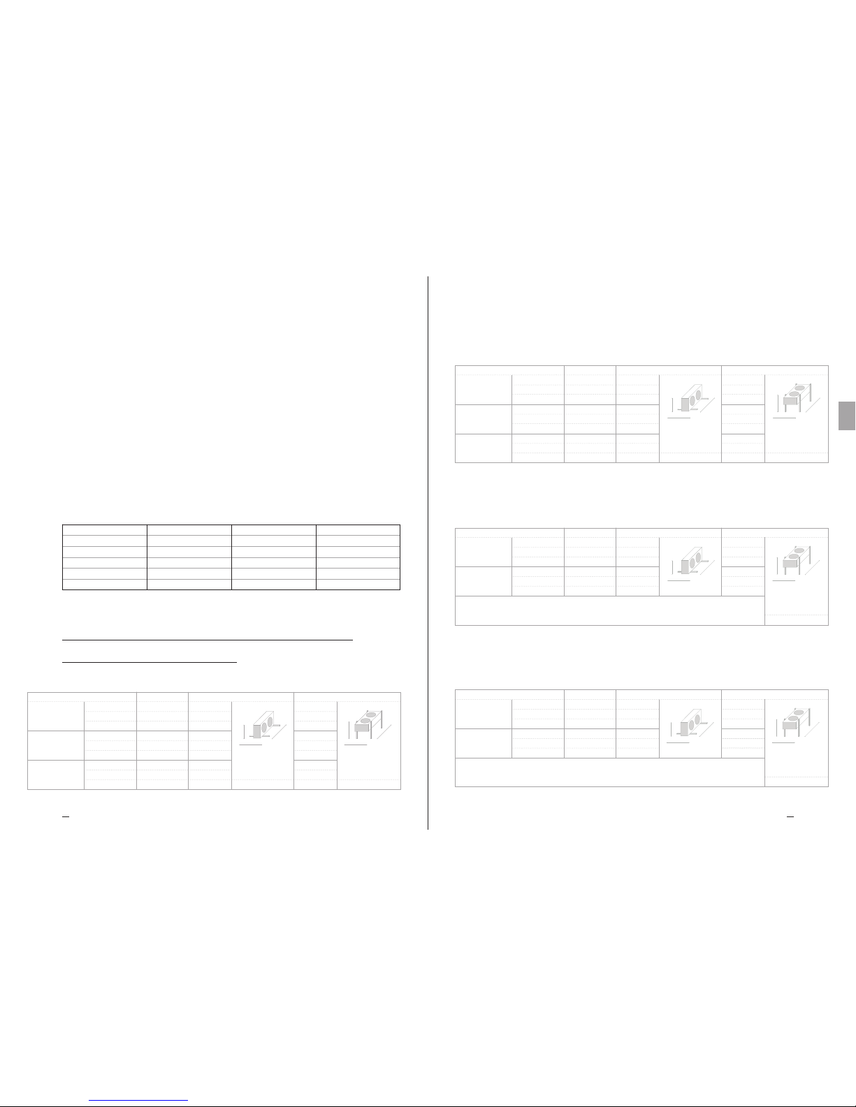
Manuel Technique TC Instruction et donnés technique
5857
Heat Exchange SolutionsThermoKey
FR
MT TC R MC FRA 04 2017MT TC R MC FRA 04 2017
TMCH1150HLLD
TMCH1150HLLY
TMCH1150HLLM
Modèle
TMCH1250HLLD
TMCH1250HLLY
TMCH1250HLLM
TMCH1350HLLD
TMCH1350HLLY
TMCH1350HLLM
Poids 38,5 kg
Volume 1,6 dm³
Connexion
Entré 1 x 22 mm
Sortie 1 x 22 mm
Poids 72 kg
Volume 2,4 dm³
Entré 1 x 22 mm
Sortie 1 x 22 mm
Poids 105,5 kg
Volume 3,2 dm³
Entré 1 x 28 mm
Sortie 1 x 28 mm
Larg.
Long.
H
Côté horizontal flux de l’air
780 mm
644 mm
1067 mm
780 mm
644 mm
1817 mm
780 mm
644 mm
2567 mm
Larg.
Long.
H
674 mm
911 mm
1067 mm
674 mm
911 mm
1817 mm
674 mm
911 mm
2567 mm
Côté vertical flux de l’air
Scale 1:20
TMCH1150HUUD
TMCH1150HUUY
TMCH1150HUUM
Modèle
TMCH1250HUUD
TMCH1250HUUY
TMCH1250HUUM
Poids 56 kg
Volume 2,8 dm³
Poids 96 kg
Volume 4,4 dm³
973 mm
1006 mm
1347 mm
Larg.
Long.
H
Larg.
Long.
H
Entré 1 x 28 mm
Sortie 1 x 28 mm
Scale 1:20
Côté horizontal flux de l’air
875 mm
943 mm
1347 mm
875 mm
943 mm
2347 mm
Connexion
Entré 1 x 22 mm
Sortie 1 x 22 mm
Côté vertical flux de l’air
973 mm
1006 mm
2347 mm
Scale 1:20
Larg.
Long.
H
Larg.
Long.
H
TMCH1163HUUD
TMCH1163HUUY
Modèle
TMCH1263HUUD
TMCH1263HUUY
Poids 63 kg
Volume 2,8 dm³
Poids 110 kg
Volume 4,4 dm³
Connexion
Entré 1 x 28 mm
Sortie 1 x 28 mm
Entré 1 x 28 mm
Sortie 1 x 28 mm
875 mm
943 mm
1347 mm
875 mm
943 mm
2347 mm
973 mm
993 mm
1347 mm
973 mm
993 mm
2347 mm
Côté horizontal flux de l’air Côté vertical flux de l’air
1X500 LL – 2X500 LL – 3X500 LL
1X500 UU – 2X500 UU
1X630 UU – 2X630 UU
Larg.
H
Long.
Larg.
H
Long.
Larg.
H
Long.
Larg.
H
Long.
Larg.
H
Long.
Larg.
H
Long.
Larg.
H
Long.
Larg.
H
Long.
Larg.
H
Long.
Larg.
H
Long.
Larg.
H
Long.
Larg.
H
Long.
Larg.
H
Long.
Larg.
H
Long.
surchauffes. Faites attention car une surchauffe peut ne pas dépendre directement d’une surintensité.
Faites attention car une fois que la température s’est abaissée le thermocontact se referme sans besoin de le
réinitialiser manuellement.
TC 8.4
Veuillez suivre avec attention les schémas électriques reportés afin d’éviter l’endommagement des moteurs (a,b,c.....)
TC 8.5
Pour les modèles qui sont équipés avec des moto-vent ilateurs qui ne sont pas standards, faites référence aux s chémas
et absorptions indiqués sur les documents supplémentaires et sur les données de la plaque.
TC 8.6
Avant d’utiliser les systèmes de régulation du nombre de tours des moto-ventilateurs, veuillez en vérier la compatibilité.
Des régulateurs non compatibles peuvent générer des bruits ou des dommages aux moto-ventilateurs. Le fabricant rejette
toute responsabilité concernant les performances des modèles équipés avec des dispositifs de régulation non spéciés au
moment de l’ore.
Nous reportons ici de suite les valeurs électriques des ventilateurs standards :
Pour d’autres versions de ventilateurs, cont actez Thermokey.
Nb de tours: 1430 tr/mn
Puissance: 160 W
Courant: 0,73 A
Nb de tours: 1340/1060 tr/mn
Puissance: 710/480 W
Courant: 1,4/0,8 A
Nb de tours: 1300 tr/mn
Puissance: 680 W
Courant: 3,0 A
Nb de tours: 1340/1070 tr/mn
Puissance: 1900/1350 W
Courant: 3,2/2,2 A
Diamètre: 400 (M)
Tension nominale: 230 V
Fréquence: 50 H
Diamètre: 500 (D/Y)
Tension nominale: 400 V
Fréquence: 50 H
Diamètre: 500 (M)
Tension nominale: 230 V
Fréquence: 50 H
Diamètre: 630 (D/Y)
Tension nominale: 400 V
Fréquence: 50 H
Larg.
Long.
H
Larg.
Long.
H
TMCH1140HLLM
TMCH1240HLLM
TMCH1340HLLM
Poids 35 kg
Volume 1,6 dm³
Poids 65 kg
Volume 2,4 dm³
Poids 95 kg
Volume 3,2 dm³
Connexion
Entré 1 x 22 mm
Sortie 1 x 22 mm
Entré 1 x 22 mm
Sortie 1 x 22 mm
Entré 1 x 28 mm
Sortie 1 x 28 mm
Modèle
Larg.
H
Long.
Côté horizontal flux de l’air
780 mm
644 mm
1067 mm
780 mm
644 mm
1817 mm
780 mm
644 mm
2567 mm
Côté vertical flux de l’air
674 mm
879 mm
1067 mm
674 mm
879 mm
1817 mm
674 mm
879 mm
2567 mm
Scale 1:20
TC 9. Caracteristiques dimensionnelles
— Donnees techniques
1X400 LL – 2X400 LL – 3X400 LL
Larg.
H
Long.
Larg.
H
Long.
Larg.
H
Long.
Larg.
H
Long.
Larg.
H
Long.
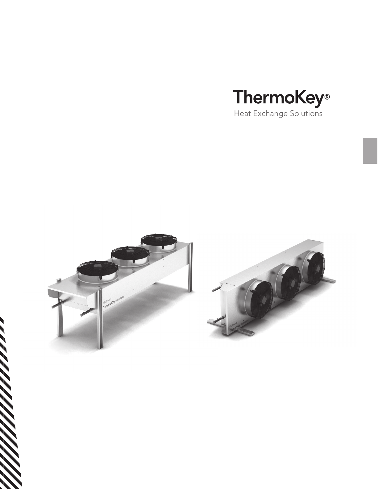
Podręcznik Techniczny TC
Seria TMC
Skraplacze serii TKSmart
ORYGINALNA WERSJA NINIEJSZEJ INSTRUKCJI JEST W
JĘZYKU WŁOSKIM.
MT TC R MC PL 04 2017
PL

Heat Exchange SolutionsThermoKey
Podręcznik Technichniczy TC Instrukje i dane technicze
6160
PL
MT TC R MC PL 04 2017MT TC R MC PL 04 2017
NALEŻY UWAŻNIE PRZECZYTAĆ I ZROZUMIEĆ WSZYSTKIE
INFORMACJE ZAWARTE W INSTRUKCJI PRZED PROJEKTOWANIEM
I KAŻDORAZOWO PRZED WYKONANIEM WSZELKICH CZYNNOŚCI
PRZENOSZENIA, ROZPAKOWYWANIA, MONTAŻU, USTAWIANIA I
URUCHAMIANIA URZĄDZENIA. FIRMA THERMOKEY NIE PONOSI ŻADNEJ
ODPOWIEDZIALNOŚCI ZA SZKODY WYRZĄDZONE W STOSUNKU DO OSÓB
LUB MIENIA, POWSTAŁE W WYNIKU NIEPRZESTRZEGANIA WSKAZÓWEK
ZAWARTYCH W NINIEJSZYM DOKUMENCIE
Oryginalna wersja tego podręcznika jest w języku włoskim, i jest dostępna na stronie internetowej:
www.thermokey.com.
Tłumaczenie na język angielski jest wierną kopią oryginalnego dokumentu i jest ono dostępne na
stronie internetowej: www.thermokey.com.
Tłumaczenia na inne języki mogą zawierać błędy; w razie wątpliwości, zawsze odnieść się do
pierwotnej wersji w języku włoskim lub jej tłumaczenia na język angielski.
Thermokey S.p.A. System Zarządzania Jakością posiada certykat zgodnie z ISO 9001,
Thermokey S.p.A. System Zarządzania Środowiskowego posiada certykat zgodnie z ISO 14001)
oraz System Zarządzania Bezpieczeństwem posiada certykat zgodnie z OHSAS 18001.

Heat Exchange SolutionsThermoKey
Podręcznik Technichniczy TC Instrukje i dane technicze
6362
PL
MT TC R MC PL 04 2017MT TC R MC PL 04 2017
TC 1. Literatura dotycząca przepisów
prawnych
Produkt opisany w niniejszym podręczniku jest zgodny z:
DYREKTYWĄ MASZYNOWĄ 2006/42/EC
DYREKTYWĄ NISKONAPIĘCIOWĄ 2006/95/EC
DYREKTYWĄ ZGODNOŚCI ELEKTROMAGNETYCZNEJ 2004/108/EC
DYREKTYWĄ W SPRAWIE URZĄDZEŃ CIŚNIENIOWYCH (PED) 97/23/EC
DYREKTYWĄ DOTYCZĄCĄ SPRAWNOŚCI ENERGETYCZNEJ (ERP) 2009/125/EC
Ryzyko porażenia prądem. Produkt jest wyposażony w wentylatory elektryczne o napięciu znamionowym trójfazowym
400V AC lub jednofazowym 230V. Przewody zasilające muszą być wyposażone w systemy ochrony przed porażeniem prądem
i w urządzenia zabezpieczające zgodnie z wymogami prawa.
Niebezpieczeństwo skaleczenia. Wymiennik ciepła, integralna część produktu, jest zbudowany z metalowych lamel o
niezabezpieczonych ostrych krawędziach. Obudowa bloku jest wykonana z blachy, która może tworzyć ostre krawędzie.
Zagrożenie od ruchomych części. Urządzenie jest wyposażone w wentylatory elektryczne z siatkami ochronnymi
wymaganymi przez prawo. W przypadku niektórych produktów może być możliwy celowy dostęp do części ruchomych
(łopatki wentylatora silnika) z obszarów niechronionych. Przed każdym uzyskaniem dostępu upewnić się, że ruchome
części nie mogą stwarzać zagrożenia dla operatorów.
Ryzyko zmiażdżenia kończyn lub korpusu ciała. Podczas załadunku, transportu i montażu, wczasie eksploatacji i
konserwacji, należy zwrócić uwagę na maksymalne znamionowe ciężary każdego produktu, aby zapobiec jego przewróceniu
się lub upadkowi niebezpiecznemu dla operatorów.
TC 2. Zagrożenia
TC 3. Ostrzeżenia
TC 3.1
Zawartość Podręcznika Technicznego Produktu:
OGÓLNE ZASADY BEZPIECZNEGO UŻYTKOWANIA (G.I.)
INSTRUKCJE DOTYCZĄCE ROZŁADUNKU I ROZPAKOWYWANIA (H.P.)
INSTRUKCJE I DANE TECHNICZNE (TC)
SZCZEGÓŁOWE INSTRUKCJE UŻYTKOWANIA I KONSERWACJI (S.I.)
TC 3.2
Niniejszy podręcznik jest w sekcji TC i zwany jest: INSTRUKCJE I DANE TECHNICZNE Podręcznika Technicznego Produktu.
W celu uzyskania wszelkich informacji nieobjętych niniejszym podręcznikiem należy odnieść się do innych sekcji
(I-II-IV), a w razie wątpliwości należy skontaktować się z producentem.
TC 3.3
Niniejszy podręcznik jest integralną częścią modelu TMC i jako taki musi być przechowywany przez cały okres
użytkowania produktu.
TC 3.4
Dodatkowa dokumentacja techniczna dotycząca produktów niestandardowych jest załączona do niniejszego
podręcznika i jest ona jego integralną częścią oraz ma specyficzny kod wskazany w dokumentach przewozowych.
TC 3.5
Produkt opisany w niniejszym podręczniku jest uważany za maszynę nieukończoną dlatego nieużyteczną wformie
dostarczonej, jednak stanowi komponent systemów klimatyzacji i chłodzenia i musi być zainstalowany iuruchomiony
TC 1. LITERATURA DOTYCZĄCA PRZEPISÓW PRAWNYCH
TC 2. ZAGROŻENIA
TC 3. OSTRZEŻENIA
TC 4. PRZEZNACZENIE
TC 5. KONTROLA, PRZEŁADUNEK I TRANSPORT
TC 6. INSTALOWANIE I URUCHOMIENIE
TC 7. KONSERWACJA OGÓLNA I KONTROLA
TC 8. SCHEMATY OKABLOWANIA WENTYLATORÓW
TC 9. WYMIARY - DANE TECHNICZNE
STRESZCZENIE
62
63
63
64
64
66
66
67
68
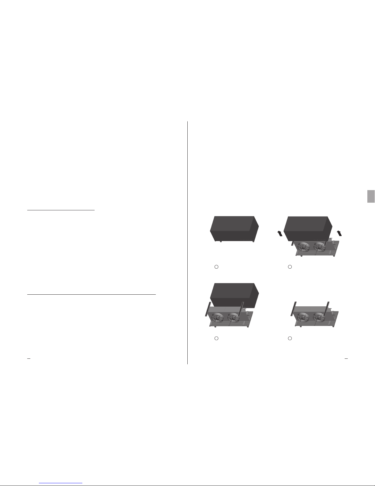
Heat Exchange SolutionsThermoKey
Podręcznik Technichniczy TC Instrukje i dane technicze
6564
PL
MT TC R MC PL 04 2017MT TC R MC PL 04 2017
przez wykwalifikowaną obsługę (patrz rozdział odnoszący się do instalacji i uruchomienia).
TC 3.6
Każdy produkt jest dostarczany z Deklaracją Włączenia EC.
TC 3.7
Dodatkowa dokumentacja produktu składająca się z katalogów, przewodników i biuletynów technicznych
pochodzi bezpośrednio od Thermokey i jest dostępna na stronie internetowej www.thermokey.com.
KATALOGI – http://www.thermokey.com/Cataloghi.aspx
PODRĘCZNIKI – http://www.thermokey.com/Manuali.aspx
TC 4. Przeznaczenie
TC 4.1
Model musi być wykorzystywany wyłącznie dla celów wskazanych poniżej, w przeciwnym razie użycie uważane jest za
niewłaściwe i zwalnia producenta od jakiejkolwiek odpowiedzialności.
TC 4.2
Skraplacze mikrokanałowe serii TKSmart znalazły zastosowanie w przemyśle HVAC&R. Produkt nie jest
dostarczany z niezależnym obiegiem dochładzającym. Parametry termodynamiczne są określone zgodnie z
normą EN327.
TC 4.3
Standardowy model jest wyposażony w wentylatory elektryczne, pracujące na fragmencie charakterystyki o zerowym sprężu
dyspozycyjnym
TC 4.4
W razie wątpliwości odnośnie zamierzonego użytkowania produktu proszę skontaktować się z producentem.
TC 5. Kontrola, przeładunek i transport
TC 5.1
Po otrzymaniu produktu należy sprawdzić integralność opakowania i produktu; natychmiast zgłosić wszelkie
uszkodzenia przewoźnikowi. Opakowanie jest produkowane zgodnie z modelem, jest dostosowane do środków
transportu i umożliwia prawidłowy przeładunek.
TC 5.2
Podczas transportu i przeładunku pakowanego produktu należy unikać nadmiernego i niewłaściwego nacisku na opakowanie.
TC 5.3
Podczas transportu i przeładunku opakowanego produktu stosować ochraniacze, aby uniknąć obrażeń spowodowanych
przez elementy opakowania, takie jak gwoździe, deski lub tektura i takie części produktu, jak lamele lub obudowa (
patrz Podręcznik Techniczny DPI, sekcja I, rozdział IG 6).
TC 5.4
Rozpakować urządzenie jak najbliżej miejsca jego instalowania (patrz także montaż i uruchomienie). Ogólnie, produkt
nie może być transportowany i przeładowywany bez oryginalnego opakowania.
TC 5.5
Podczas przenoszenia rozpakowanego produktu, do instalowania należy używać ochraniaczy aby uniknąć obrażeń
spowodowanych przez ostre krawędzie lamel lub obudowy ( patrz Instrukcja Techniczna DPI, sekcja I, rozdział IG 6).
Poniżej podano procedurę rozpakowywania:
Dostarczony TKSmart
Odkręcić 4 śruby
Zdjąć karton
Proszę zapoznać się szczegółowo z
dołączoną dokumentacją
1
3
2
4

Heat Exchange SolutionsThermoKey
Podręcznik Technichniczy TC Instrukje i dane technicze
6766
PL
MT TC R MC PL 04 2017MT TC R MC PL 04 2017
TC 6.1
Instalowanie i uruchomienie urządzenia musi być wykonywane przez wykwalifikowany i doświ adczony personel.
TC 6.2
Sprawdzić, czy konstrukcje wsporcze i zakotwienia odpowiadają ciężarowi i kształtowi produktu (patrz rozdział
Wymiary i dane techniczne).
TC 6.3
Zamocować produkt do wszystkich punktów przewidzianych w instrukcji (patrz rozdział Wymiary) za pomocą
odpowiednich kotew i odpowiednio do całkowitego ciężaru (ciężar netto produktu, ciężar czynnika chłodniczego, ciężar
wymiennika ciepła, ciężar jakiejkolwiek akumulacji śniegu).
TC 6.4
Produkt nie jest przeznaczony do dodatkowego obciążania.
TC 6.5
Sprawdzić, czy zasilanie elektryczne jest zgodne ze specyfikacjami, które podano na tabliczce znamionowej.
TC 6.6
Przed podłączeniem urządzenia sprawdzić obecność elementów wyłączających i dzielących na przewodzie zasilającym,
zabezpieczenia przed porażeniem prądem elektrycznym, zabezpieczenia urządzeń i wykonać wszelkie inne sprawdzenia
wymagane przez obowiązujące przepisy.
TC 6.7
Jeśli stosowane są jakiekolwiek układy regulacji prędkości obrotowej wentylatora elektrycznego, sprawdzić ich
kompatybilność. Niekompatybilne urządzenia mogą generować hałas i mogą uszkodzić silniki; Producent nie
gwarantuje osiągnięcia parametrów znamionowych dla modeli wyposażonych w urządzenia sterujące.
TC 6.8
Sprawdzić, czy warunki pracy (wilgotność, temperatura i ciśnienie) są zgodne z parametrami technicznymi produktu.
TC 6.9
Dostęp do zainstalowanego produktu, dla każdego rodzaju interwencji, powinien być możliwy wyłącznie dla doświadczonych
pracowników zakwalikowanych do uruchomienia systemu zgodnie z obowiązującymi przepisami.
TC 6. Instalowanie i uruchomienie
TC 7. Konserwacja ogólna i kontrola
TC 7.1
Przed wykonaniem jakichkolwiek prac konserwacyjnych należy upe wnić się, że przewód zasilający produkt jest
dzielony: części elektryczne mogą być podłączone do automatycznych elementów sterujących. Wszystkie prace
konserwacyjne powinny być wykonywane przez wykwalifikowany i doświadczony personel.
TC 7.2
Produkt ten składa się przede wszystkim z lamelowego wymiennika ciepła w technologii mikrokanałowej, obudowy z
blachy aluminiowej i wentylatorów elektrycznych.
TC 7.3
Okresowo sprawdzać mocowanie urządzenia, przyłącza elektryczne i przyłącza do linii chłodniczej.
TC 7.4
Zapewnić okresowe czyszczenie obudowy i samego wymiennika ciepła przy użyciu odpowiednich detergentów lub ewentualnie
wody i mydła o neutralnym pH. Nie należy używać żrących detergentów, rozpuszczalników, kwasowych ani zasadowych
roztworów zawierających głównie miedź, chlor lub amoniak. Całkowicie unikać stosowania materiałów ściernych. Jeśli
wymagane jest stosowanie środków odkażających, to należy sprawdzić, czy można je stosować dla danych materiałów. W
razie wątpliwości należy skontaktować się z producentem i p oprosić o instrukcję „ jak obsługiwać bloki mikrokanałowe”.
TC 7.5
Częstotliwość przeglądów i konserwacji zależy od rodzaju instalacji, dlatego powinna być ona ustalona przez
doświadczonych i wykwalifikowanych pracowników.
TC 7.6
W przypadku każdej operacji na produkcie nieopisanej w niniejszym podręczniku, należy skontaktować się zproducentem.
TC 7.7
Unikać wykonywania ustawień on/off zarówno po stronie powietrza, jak i po stronie czynnika chłodniczego, gdy
temperatura powietrza jest niższa niż -10stC, w celu uniknięcia gwałtownych zmian.
TC 7.8
Wentylatory elektryczne są wyposażone w wytrzymałą kratkę ochronną, aby umożliwić wykonywanie wszelkich
operacji wymiany na zewnątrz.
TC 8. Schematy okablowania wentylatorów
TC 8.1
Rama każdego produktu jest wyposażona w przewód uziemienia (PE) ze znacznikiem identyfikacyjnym. Należy
obowiązkowo podłączyć przewód uziemienia urządzenia do instalacji lub do zewnętrznego prze wodu ochronnego.
TC 8.2
W modelach z okablowanymi wentylatorami elektrycznymi należy obowiązkowo podłączyć przewody ochronne
wentylatorów elektrycznych do instalacji lub do zewnętrznego przewodu ochronnego.
TC 8.3
Wymagane jest stosowanie systemów przeciwporażeniowych oraz zabezpieczeń nadprądowych na liniach zasilania
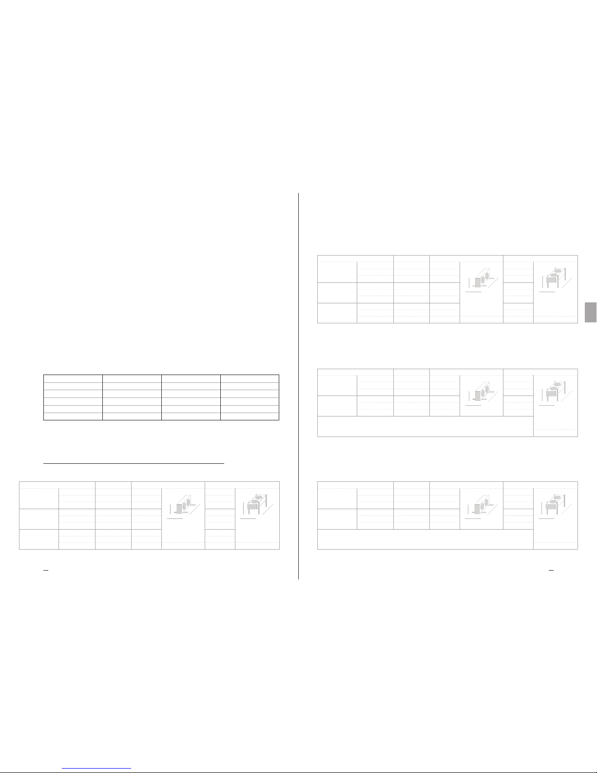
Heat Exchange SolutionsThermoKey
Podręcznik Technichniczy TC Instrukje i dane technicze
6968
PL
MT TC R MC PL 04 2017MT TC R MC PL 04 2017
wentylatorów. Wentylatory są wyposażone w wyłączniki termiczne wbudowane w uzwojenie silnika. Należy podłączyć
wyłączniki termiczne w celu zabezpieczenia silnika przed przegrzaniem. Trzeba zauważyć, że przegrzanie może nie być
bezpośrednio związane z prądem przetężeniowym..
Istotne jest, że wyłącznik termiczny zamyka się bez ręcznego resetu, kiedy temperatura spada.
TC 8.4
Podłączać ściśle według schematów okablowania w celu uniknięcia uszkodzenia silników (a, b, c .....)
TC 8.5
W modelach wyposażonych w nietypowe wentylatory elektryczne, należy zapoznać się ze schematami elektrycznymi
i tabelą poboru mocy, pokazanymi na załączonych arkuszach i na tabliczce znamionowej.
TC 8.6
Przed rozpoczęciem użytkowania systemów regulacji prędkości wentylatorów elektr ycznych sprawdzić ich kompatybilność
- niekompatybilne sterowniki mogą generować hałas i mogą również uszkodzić wentylatory; Producent nie ponosi żadnej
odpowiedzialności za wydajność produktów wyposażonych w systemy sterowania, jeżeli nie są określone w ofercie.
Parametry elektryczne standardowych wentylatorów:
W przypadku innych wersji wentylatorów, proszę skontaktować się z Thermokey.
Obroty: 1430 rpm
Moc: 160 W
Prąd: 0,73 A
Obroty: 1340/1060 rpm
Moc: 710/480 W
Prąd: 1,4/0,8 A
Obroty: 1300 rpm
Moc: 680 W
Prąd: 3,0 A
Obroty: 1340/1070 rpm
Moc: 1900/1350 W
Prąd: 3,2/2,2 A
Średnica: 400 (M)
Napięcie znamionowe: 230 V
Częstotliwość: 50 H
Średnica: 500 (D/Y)
Napięcie znamionowe: 400 V
Częstotliwość: 50 H
Średnica: 500 (M)
Napięcie znamionowe: 230 V
Częstotliwość: 50 H
Średnica: 630 (D/Y)
Napięcie znamionowe: 400 V
Częstotliwość: 50 H
W
L
H
W
L
H
TMCH1140HLLM
TMCH1240HLLM
TMCH1340HLLM
Ciężar 35 kg
Objętość 1,6 dm³
Ciężar 65 kg
Objętość 2,4 dm³
Ciężar 95 kg
Objętość 3,2 dm³
Przyłącze
We 1 x 22 mm
Wy 1 x 22 mm
We 1 x 22 mm
Wy 1 x 22 mm
We 1 x 28 mm
Wy 1 x 28 mm
Przyłącze
W
H
L
Wymiary przy przepływie poziomym
780 mm
644 mm
1067 mm
W
H
L
780 mm
644 mm
1817 mm
W
H
L
780 mm
644 mm
2567 mm
W
H
L
Wymiary przy przepływie pionowym
674 mm
879 mm
1067 mm
W
H
L
674 mm
879 mm
1817 mm
W
H
L
674 mm
879 mm
2567 mm
Skala 1:20
TMCH1150HLLD
TMCH1150HLLY
TMCH1150HLLM
Przyłącze
TMCH1250HLLD
TMCH1250HLLY
TMCH1250HLLM
TMCH1350HLLD
TMCH1350HLLY
TMCH1350HLLM
Ciężar 38,5 kg
Objętość 1,6 dm³
Przyłącze
We 1 x 22 mm
Wy 1 x 22 mm
Ciężar 72 kg
Objętość 2,4 dm³
We 1 x 22 mm
Wy 1 x 22 mm
Ciężar 105,5 kg
Objętość 3,2 dm³
We 1 x 28 mm
Wy 1 x 28 mm
W
L
H
Wymiary przy przepływie poziomym
W
H
L
780 mm
644 mm
1067 mm
W
H
L
780 mm
644 mm
1817 mm
W
H
L
780 mm
644 mm
2567 mm
W
L
H
W
H
L
674 mm
911 mm
1067 mm
W
H
L
674 mm
911 mm
1817 mm
W
H
L
674 mm
911 mm
2567 mm
Wymiary przy przepływie pionowym
Skala 1:20
TMCH1150HUUD
TMCH1150HUUY
TMCH1150HUUM
Przyłącze
TMCH1250HUUD
TMCH1250HUUY
TMCH1250HUUM
Ciężar 56 kg
Objętość 2,8 dm³
Wei ght 96 kg
Objętość 4,4 dm³
W
H
L
973 mm
1006 mm
1347 mm
W
L
H
W
L
H
We 1 x 28 mm
Wy 1 x 28 mm
Skala 1:20
W
H
L
Wymiary przy przepływie poziomym
875 mm
943 mm
1347 mm
W
H
L
875 mm
943 mm
2347 mm
Przyłącze
We 1 x 22 mm
Wy 1 x 22 mm
Wymiary przy przepływie pionowym
W
H
L
973 mm
1006 mm
2347 mm
Skala 1:20
W
L
H
W
L
H
TMCH1163HUUD
TMCH1163HUUY
Przyłącze
TMCH1263HUUD
TMCH1263HUUY
Ciężar 63 kg
Objętość 2,8 dm³
Ciężar 110 kg
Objętość 4,4 dm³
Przyłącze
We 1 x 28 mm
Wy 1 x 28 mm
We 1 x 28 mm
Wy 1 x 28 mm
W
H
L
W
H
L
875 mm
943 mm
1347 mm
W
H
L
W
H
L
875 mm
943 mm
2347 mm
973 mm
993 mm
1347 mm
973 mm
993 mm
2347 mm
Wymiary przy przepływie poziomym Wymiary przy przepływie pionowym
TC 9. Wymiary — Dane techniczne
1X400 LL – 2X400 LL – 3X400 LL
1X500 LL – 2X500 LL – 3X500 LL
1X500 UU – 2X500 UU
1X630 UU – 2X630 UU
ThermoKey Spa
via dell’Industria, 1 - 33050
Rivarotta di Rivignano Teor (UD) - Italy
T. +39 0432 772300
F. +39 0432 779734
info@thermokey.com
www.thermokey.com
MT TC R MC GEN 04 2017
 Loading...