

ThermoKey DFX 150 45 06, DFX 150 70 06, DFX 250 45 06, DFX 150 10 06, DFX 250 10 06 Technical Manual
...
MT TC A DF GEN 04 2017
Technical Manual – TC
Technisches Handbuch – TC
Manuel Technique – TC
Manuale tecnico – TC
Manual técnico – TC
PodrEcznik techniczny – TC
Series DFX, DFB, DFN, DFC
Industrial dual flow unit coolers and brine coolers
Serie DFX, DFB, DFN, DFC
Hochleistungsverdampfer mit Doppelblock
und Kaltsole-Verdampfer für den Industriegebrauch
Série DFX, DFB, DFN, DFC
Évaporateurs et frigorifères industriels double flux
Serie DFX, DFB, DFN, DFC
Aeroevaporatori e aerorefrigeratori industriali a doppio flusso
Serie DFX, DFB, DFN, DFC
Aeroevaporadores y aerorrefrigeradores industriales double flujo
Seria DFX DFB DFN DFC
Chłodnice z podwójnym wydmuchem powietrza
THE ORIGINAL VERSION OF THESE
INSTRUCTIONS IS IN ITALIAN
EN
IT
DE
ES
FR
PL

EN TECHNICAL MANUAL – TC
IT MANUALE TECNICO – TC
DE TECHNISCHES HANDBUCH – TC
ES MANUAL TÉCNICO – TC
FR MANUEL TECHNIQUE – TC
PL PODRECZNIK TECHNICZNY – TC
LANGUAGES SUMMARY
04
31
58
85
112
139
03MT TC A DF GEN 04 2017
ThermoKey
02
EN
MT TC A DF EN 04 2017
Technical Manual – TC
Series DFX, DFB, DFN, DFC
Industrial dual flow unit coolers
and brine coolers
THE ORIGINAL VERSION OF THESE
INSTRUCTIONS IS IN ITALIAN
MT TC A DF EN 04 2017
EN
Heat Exchange SolutionsThermoKey Technical Manual TC Instruction and technical data
0605
EN
MT TC A DF EN 04 2017MT TC A DF EN 04 2017
CAREFULLY READ AND FULLY UNDERSTAND ALL INFORMATION
CONTAINED IN THESE INSTRUCTIONS PRIOR TO DESIGNING AND
IN ANY CASE BEFORE PERFORMING ANY HANDLING, UNPACKING,
ASSEMBLING, INSTALLATION AND COMMISSIONING OF THE UNIT.
THE MANUFACTURER ACCEPTS NO RESPONSIBILITY FOR DAMAGE TO
PERSONS OR PROPERTY RESULTING FROM FAILURE TO FOLLOW THE
INSTRUCTIONS CONTAINED HEREIN.
The original language of this manual is Italian, and it is available on the website:
www.thermokey.com.
The English translation is a true copy of the original document and it is available on the website:
www.thermokey.com.
Translations in other languages may contain errors; if in doubt, always refer to the original
version in Italian or its English translation.
ThermoKey S.p.A. Quality Management System is certified in conformity with ISO 9001,
ThermoKey S.p.A. Environmental Management System is certified in conformity with ISO 14001
and Safe Management System is certified in conformity with OHSAS 18001.
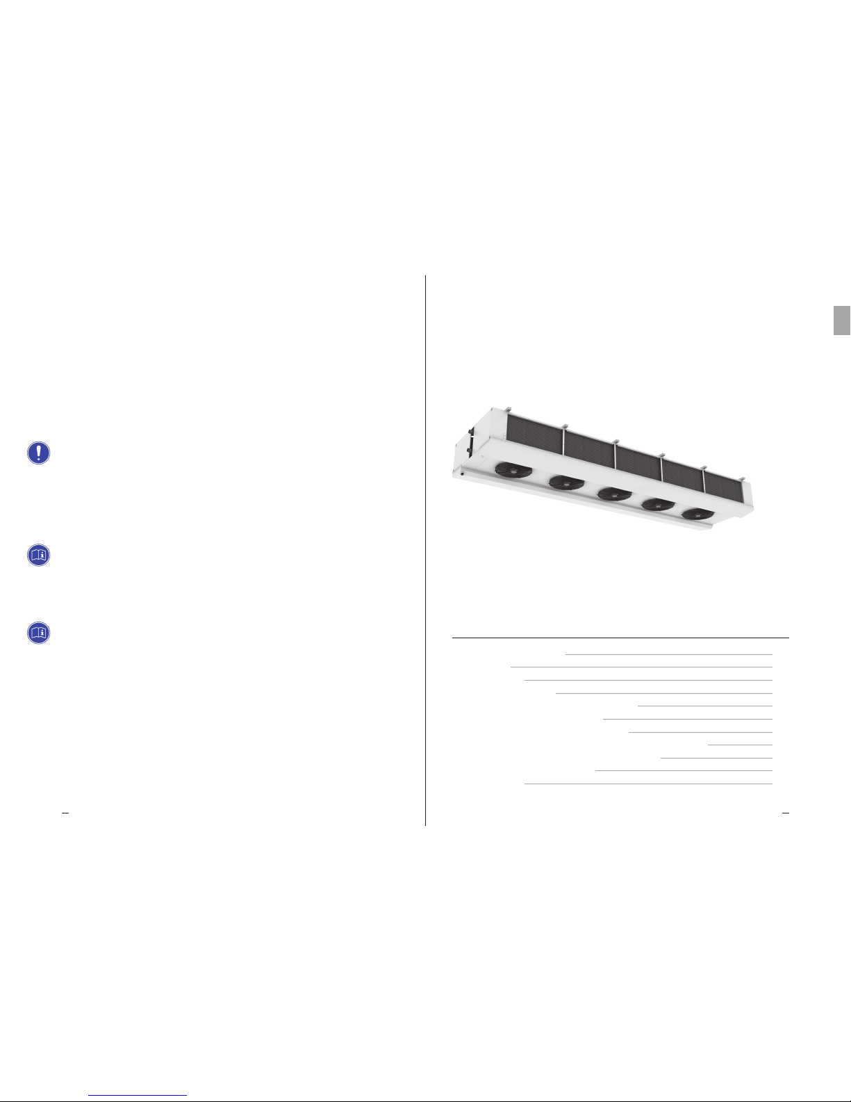
Dual Flow
Industrial Unit Cooler
TC 1. STANDARD AND DIRECTIVES REFERENCES
TC 2. HAZARDS
TC 3. WARNINGS
TC 4. INTENDED USE
TC 5. INSPECTION, HANDLING AND TRANSPORT
TC 6. INSTALLATION AND COMMISSIONING
TC 7. GENERAL MAINTENANCE AND OVERALL CONTROL
TC 8. WIRING DIAGRAMS OF ELECTRIC DEFROSTING HEATERS
TC 9. WIRING DIAGRAMS OF FANMOTORS
TC 10. DIMENSIONS
TC 11. TECHNICAL DATA
SUMMARY
07
07
08
09
09
10
13
15
20
24
28
Heat Exchange SolutionsThermoKey Technical Manual TC Instruction and technical data
0807
EN
MT TC A DF EN 04 2017MT TC A DF EN 04 2017
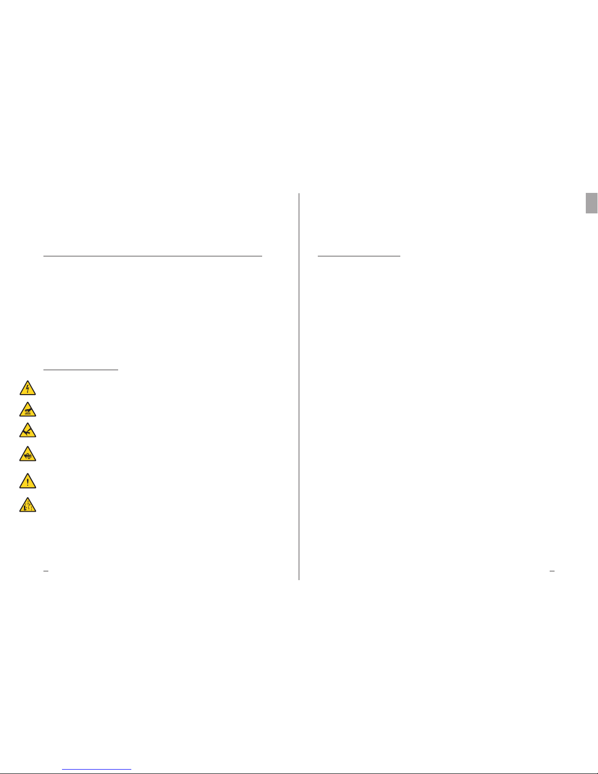
Danger of electrocution. The product is fitted with electric fanmotors and electric defrosting heating elements with
nominal operational low three-phase or single-phase voltage. The electric power supply lines will have to use protection
systems against electric shock and protection equipment required by law.
Risk of burns. In products fitted with electric defrosting heating elements the surface temperatures of the external armor
can reach about 350 °C if left on without control.
Risk of cutting. The internal heat exchanger is made of metal fins with unprotected sharp edges. The casing is made of
metal sheet components that may have unprotected sharp edges.
Danger of moving parts. The product is fitted with electric fanmotors equipped with a protection grille as provided by
law. For some products, it may be possible to deliberately access moving parts (fanmotor blades) from non-protected areas.
Before any access make sure that the moving parts do not constitute a hazard to operators.
Danger of squashing limbs or persons. During handling, transportation and installation, operation and maintenance,
pay maximum attention to the indicated weight of each product to prevent tipping over or dangerous falls towards the
operators.
Danger of falling objects. The products are fitted with doors, trays or covering metal sheet parts that during installation
or maintenance may be dismounted by removing the fastening screws; please take all appropriate precautions.
TC 2. Hazards
TC 1. Standard and directives references
The product described in this manual is compliant with:
MACHINERY DIRECTIVE 2006/42/EC
LOW VOLTAGE DIRECTIVE 2014/35/EU
ELECTROMAGNETIC COMPATIBILITY DIRECTIVE 2014/30/EU
PED DIRECTIVE 2014/68/EU
ERP DIRECTIVE 2009/125/EC
TC 3. Warnings
TC 3.1
Contents of the Product Technical Manual:
INSTRUCTIONS FOR SAFE USE (IG)
INSTRUCTIONS FOR HANDLING AND UNPACKING (IM)
INSTRUCTIONS AND TECHNICAL DATA (TC)
SPECIFIC INSTRUCTIONS FOR USE AND MAINTENANCE (IS)
TC 3.2
This manual is section TC, called INSTRUCTIONS AND TECHNICAL DATA, of the Product Technical Manual.
For any information not covered in this manual, please refer to the other sections (IG-IM-IS) and, if in doubt, contact
the Manufacturer.
TC 3.3
This manual is an integral part of the DFX DFB DFN and DFC units and as such it must be kept throughout the
operational life of the product.
TC 3.4
Any additional technical documentation relating to the non-standard products is attached to this manual becoming
an integral part of it and is identified with a specific code indicated on the shipping documents.
TC 3.5
The product described in this manual is considered a partly completed machine, therefore not usable as supplied, but
it is a component for air conditioning and refrigeration systems and must be installed and commissioned by qualified
operators (see the chapter related to installation and put in function).
TC 3.6
Each product is supplied with EC Declaration of Incorporation.
TC 3.7
Additional product documentation, consisting of catalogues, guides and technical bulletins, is provided directly
by ThermoKey and it is available on our website www.thermokey.com.
CATALOGUES – http://www.thermokey.com/Cataloghi.aspx
MANUALS – http://www.thermokey.com/Manuali.aspx

Heat Exchange SolutionsThermoKey Technical Manual TC Instruction and technical data
1009
EN
MT TC A DF EN 04 2017MT TC A DF EN 04 2017
TC 4. Intended use
TC 4.1
The unit should be used exclusively for the purpose indicated below, otherwise its use is considered improper and
exempts the manufacturer from any responsibility.
TC 4.2
The industrial evaporator unit cooler and brine cooler from the series DFX DFN DFB and DFC are designed for use
in all food sectors, in medium and large cold storage rooms or refrigerated warehouses for storing fresh and frozen
goods and also for cooling and air conditioning medium and large processing rooms. All standard units are equipped
with a highly efficient ventilation group for optimal air distribution.
TC 4.3
The standard unit is equipped with fanmotors not designed to withstand additional external static pressure such as
those exerted by additional ducts, abatement tunnels, etc.
TC 4.4
When in doubt on the intended use please contact the Manufacturer.
TC 5. Inspection, handling and transport
TC 5.1
Upon receipt of the unit, check the integrity of the packaging and of the product; immediately notify the carrier of any
possible damage occurred. The packaging is manufactured in accordance with the unit and the appropriate means of
transport and handling.
TC 5.2
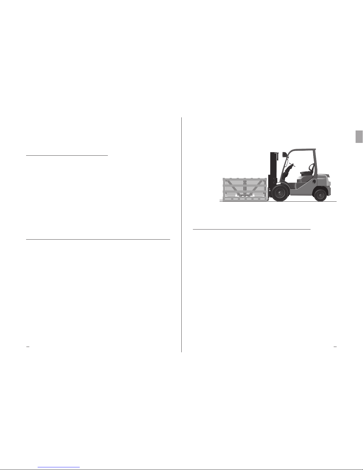
During transport and handling of the unit in its packaging, avoid improper and non-compliant stress on the packed
product, comply with all indications and always keep the unit in the position shown in the figure (see fig.1).
TC 5.3
During transport and handling of the packed product, use appropriate protection to avoid injury from packaging parts
such as nails, wooden boards or cardboards and from parts of the unit like fins or casing parts (see DPI Technical
Manual Section I chapter IG 6).
TC 5.4
Unpack the unit as close as possible to the installation site (see also chapter installation and commissioning). In
general, the unit should not be transported or handled without its original packaging.
TC 5.5
During handling of the unpacked unit for installation, use protection to prevent injuries from sharp edges like ns or casing
parts (see DPI Technical Manual Section I chapter IG 6).
TC 6.1
The installation and commissioning of the unit must be carried out by expert and qualified personnel. For fixing
follow the diagram shown in the figure (see fig.2).
TC 6.2
For proper air circulation, verify that the installation environment provides adequate free volumes and air passages
suitable to the airflow and air throw of the unit. Otherwise the declared performance may not be guaranteed and
operating defects may occur. Be careful not to block the inlet or the outlet air flow of the fanmotors and the heat
exchangers (see fig.3).
TC 6.3
Check that the support structures and anchoring devices comply with the weight and shape of the unit (see chapters
Dimensions and Technical Data).
TC 6.4
Fix the unit to all provided fixing points (see chapter Dimensions) with adequate anchors in accordance with the total
weight that it could reach (net weight of the unit, weight of the refrigerant, weight of any ice accumulation on the heat
exchanger, weight of any accumulation in the drip trays).
TC 6.5
The unit is not designed to support additional loads.
TC 6.6
In models with electric defrost option, make sure to guarantee or provide adequate space to allow the replacement of
the heating elements in the heat exchangers.
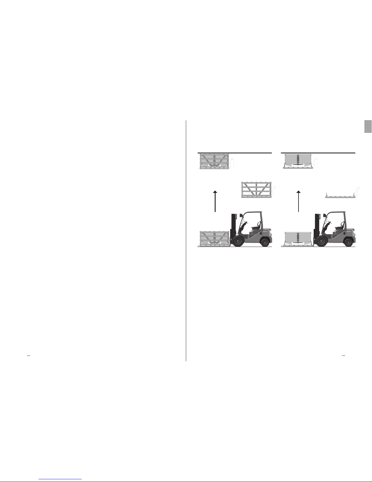
fig.1 - For safe handling the forks must always
protrude from the wooden cage.
TC 6. Installation and commissioning
Heat Exchange SolutionsThermoKey Technical Manual TC Instruction and technical data
1211
EN
MT TC A DF EN 04 2017MT TC A DF EN 04 2017
TC 6.7
In environments with multiple units no alternating defrosting cycles should be carried out, in order to avoid the
abnormal formation of frost on the heat exchangers.
TC 6.8
Check that the power line is compliant with the requirements of the unit shown on the technical data label.
TC 6.9
Before connecting the unit, verify the presence of disconnecting and breaking devices on the power supply line,
protection against electric shock, protection of equipment and any other device required by law. Standard models
are supplied with junction boxes for the supply of fanmotors and with junction boxes for the supply of the heating
elements in models with electric defrosting.
TC 6.10
If speed controls are used for the fanmotors, check their compatibility. Non-compliant devices may generate noise and
damage the fanmotors. The manufacturer does not guarantee the indicated performance of units equipped with speed
controllers.
TC 6.11
Verify that the line of the refrigerant is adequate for the performance of the unit. When connecting the cooling circuit,
do not deform the capillaries and do not change the position of the distributor or the manifolds in general.
TC 6.12
Verify that the operating condition limits (humidity, temperature and pressure) meet the specific requirements of the
product selection.
TC 6.13
For units with electrical defrosting and, depending on the type of cold room, correctly dene the time and the number of
defrosting cycles. e defrosting cycle must be controlled with a chrono-thermostat and the temperature probes should
not stop the defrosting cycle prematurely but only prevent overheating. e probes must be placed in the coldest parts
of the heat exchanger (where there is the greatest frost formation) and at a distance from the heating elements.
TC 6.14
Make sure that at the end of each defrosting cycle (electric, hot gas or warm glycol), the finned pack, the internal
drip tray and the drain dischargers are clean. If necessary, correct the timing and the number of the defrosting cycles.
Accumulations of frost tend to turn into harmful ice accumulations that may cause malfunctioning or the failure of
the heat exchanger.
TC 6.15
Install the appropriate siphons on the drain discharge line and verify their effectiveness at all operating temperatures.
In low temperature rooms functioning below the freezing point, the external moisture entering from the discharge
line, if not provided with siphons, generates harmful ice accumulations.
TC 6.16
Access to the installed unit, for any type of intervention, should be reserved to experienced personnel specically trained to
run the system, in compliance with current regulations.
fig.2 – Fixing sequence:
a) Remove the top of the wooden cage.
b) Possible easy installation sequence only for standard models with up to maximum two fanmotors, remove also the sides
and the ends of the wooden cage.
c) Lift and position.
d) Fix the unit to all appropriate points (see chapter dimensions) with adequate anchors in accordance with the total
weight (net weight of the unit, weight of the refrigerant, weight of any ice accumulation on the heat exchanger, weight of
any accumulation in the drip trays).
e) Remove the wooden cage and the transport brackets.
f) Remove the bottom of the wooden cage and the transport brackets.
c) e d)
c) e d)
a) e b)
e) f)
a)
Heat Exchange SolutionsThermoKey Technical Manual TC Instruction and technical data
1413
EN
MT TC A DF EN 04 2017MT TC A DF EN 04 2017
TC 7. General maintenance and overall control
TC 7.1
Before performing any maintenance, make sure that the power supply of the unit has been sectioned off: the
electrical parts may be connected to automatic controls. All maintenance operations must be carried out by
qualified and experienced personnel.
TC 7.2
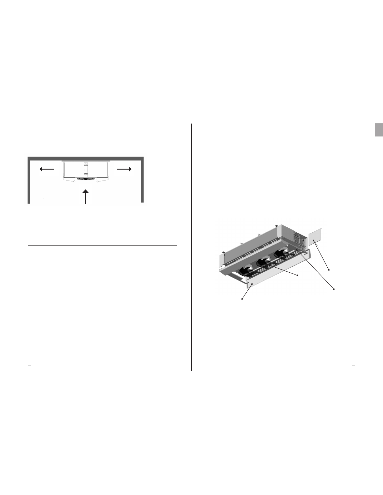
The unit mainly consists of: a finned pack heat exchanger, a structural frame in metal sheet panels, metal sheet covers,
accessible drip trays and fanmotors. In units with electric defrosting, stainless steel armoured heating elements with
vulcanised terminals are enclosed in the heat exchanger and mounted on the drip trays with locking devices that
prevent displacement (see fig.4).
TC 7.3
Periodically check the fixing points of the unit, the electrical connections and the connections to the refrigerant line.
TC 7.4
Provide for periodic cleaning of the casing and the exchanger using suitable detergents or possibly water with neutral
pH soap. Do not use aggressive cleaning agents, solvents, acids or basic solutions containing chlorine or ammonia.
Avoid the use of abrasives in general. In case of use of sanitising agents, check their compatibility with the materials.
If in doubt, contact the Manufacturer.
TC 7.5
Check the effectiveness of defrosting. For units with electric defrosting, periodically check the operation of all heating
elements. The Manufacturer will not respond in any way for damages and defects caused by undetected malfunctions
(eg. harmful ice accumulations).
fig.3 – Minimum distance from walls
N.B.: Be careful not to block the inlet or the outlet air flow of the fanmotors and the heat exchangers.
<< MIN. 1m >> << MIN. 1m >>
TC 7.6
Provide for the replacement of faulty heating elements. Pay special attention during installation to prevent damage to
vulcanised insulations; properly restore all connections (see enclosed diagrams) and all locking systems to prevent the
displacement of the same during operation.
TC 7.7
Inspection and maintenance intervals depend on the type of cell, therefore they need to be defined by qualified and
experienced personnel.
TC 7.8
For any operation on the unit not described in this manual, please contact the Manufacturer.
fig.4 – Components
a) The front covers are removable to facilitate access to the manifolds compartment during the installation and maintenance
phases. The closing covers are assured by screws.
b) The lower covers are removable to allow full access to the manifolds compartment.
c) The drip trays are fitted with hinges for easy access to the internal drip tray to allow replacement of the defrosting
heating elements or for cleaning operations. They can be disassembled if replacement is needed.
d) Each fanmotor is equipped with a structural guard grille wich allows replacement operations completely from the
outside.
REMOVABLE
LOWER COVERS
FRONT COVERS
THAT CAN BE
OPENED
HINGED
EXTERNAL DRIP
TRAYS
FANMOTORS
Heat Exchange SolutionsThermoKey Technical Manual TC Instruction and technical data
1615
EN
MT TC A DF EN 04 2017MT TC A DF EN 04 2017
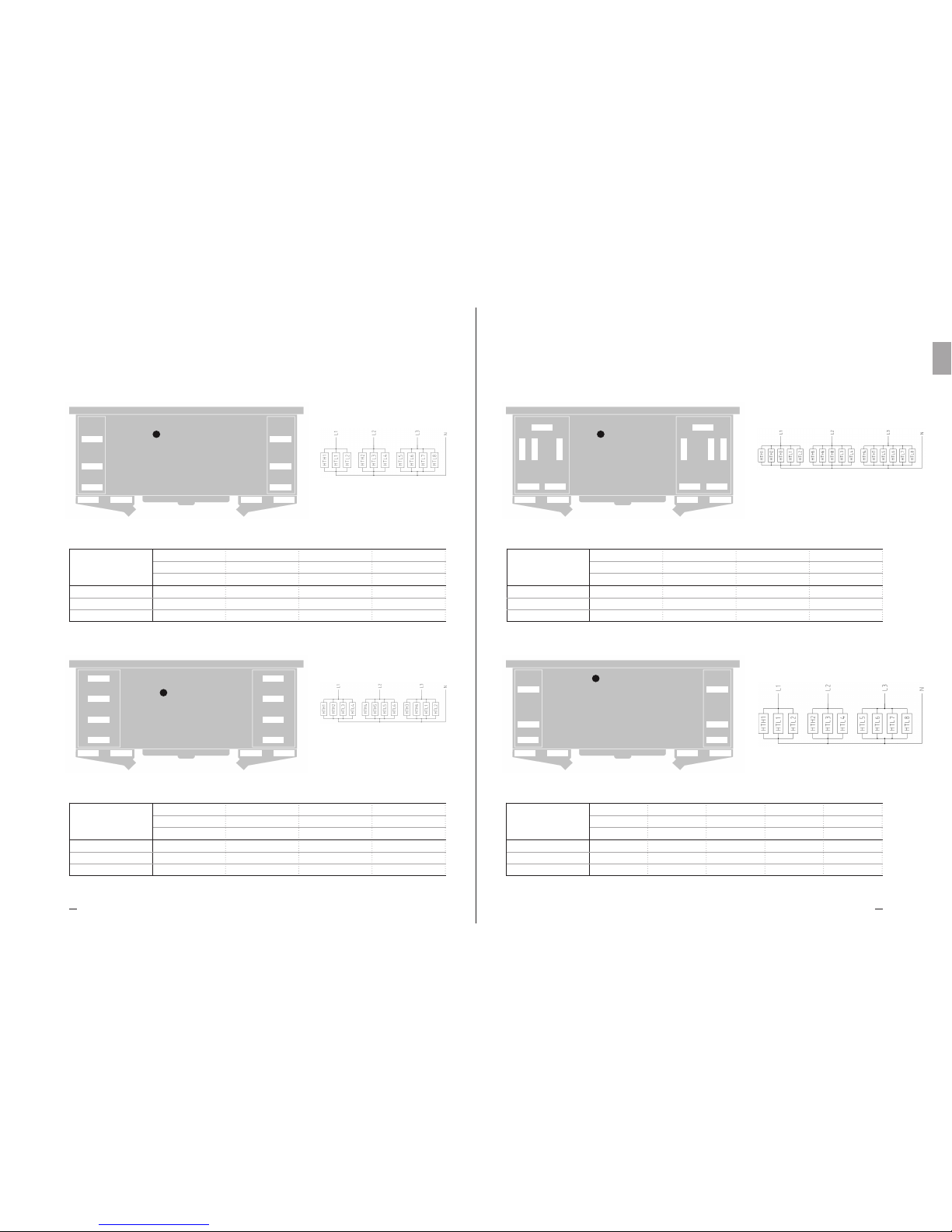
TC 8. Wiring diagrams and power rating of
electric heaters
TC 8.1
The casing of each unit is equipped with ground terminal (PE) with an identification label.
It is mandatory to connect the ground terminal of the unit to the external protective conductor or earthing
system.
TC 8.2
It is mandatory to use protection systems against electric shock and equipment protection devices on the supply lines
of the defrosting heaters.
TC 8.3
Periodically check the efficiency of all electric heaters to prevent the unit from forming dangerous ice accumulations
caused by any undetected malfunctions.
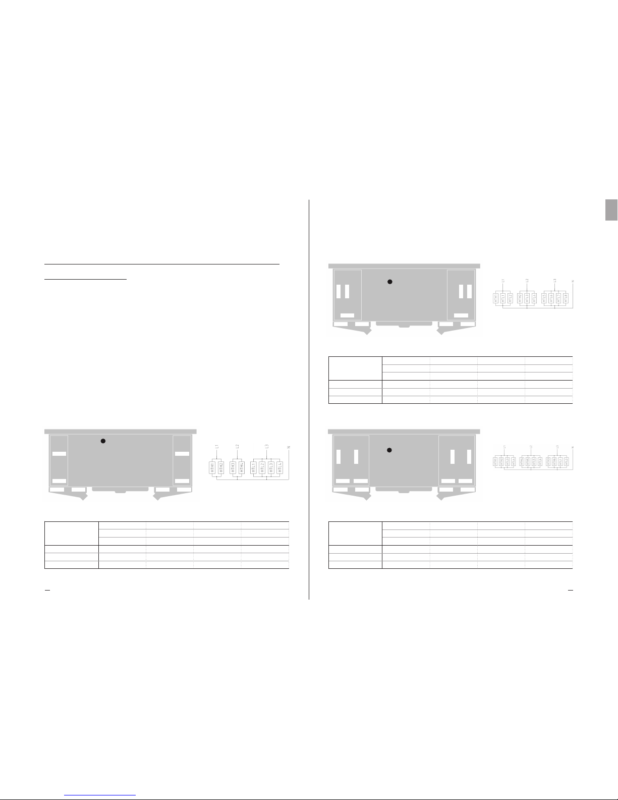
DFX DFB DFN DFC Ø 500 mm 04 RR
SUPPLY LINE ~3 400V 50-60HZ
STAR CONNECTION WITH NEUTRAL
Coil power
Drip tray power
Total power
3400
1700
5100
6800
3400
10200
10200
5100
15300
13600
6800
20400
150 45 04
150 70 04
150 10 04
250 45 04
250 70 04
250 10 04
350 45 04
350 70 04
350 10 04
450 45 04
450 70 04
450 10 04
MODELS
DFX DFB DFN DFC
(W)
(W)
(W)
HTH1
HTH2
HTH3
HTH4
HTL1 HTL3HTL2 HTL4
PE
HTH = High power electric heater (*) HTL = Low power electric heater (*)
(*) The HTH High power heater has twice the power of the low power heater HTL
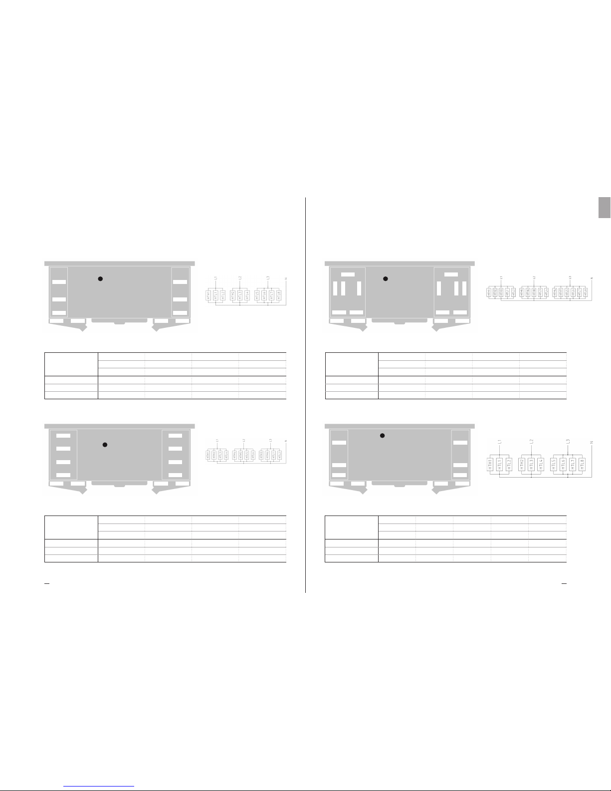
Coil power
Drip tray power
Total power
5950
1700
7650
11900
3400
15300
17850
5100
22950
23800
6800
30600
150 45 08
150 70 08
150 10 08
250 45 08
250 70 08
250 10 08
350 45 08
350 70 08
350 10 08
450 45 08
450 70 08
450 10 08
MODELS
DFX DFB DFN DFC
(W)
(W)
(W)
Coil power
Drip tray power
Total power
3400
1700
5100
6800
3400
10200
10200
5100
15300
13600
6800
20400
150 45 06
150 70 06
150 10 06
250 45 06
250 70 06
250 10 06
350 45 06
350 70 06
350 10 06
450 45 06
450 70 06
450 10 06
MODELS
DFX DFB DFN DFC
(W)
(W)
(W)
DFX DFB DFN DFC Ø 500 mm 06 RR
DFX DFB DFN DFC Ø 500 mm 08 RR
HTH = High power electric heater (*) HTL = Low power electric heater (*)
(*) The HTH High power heater has twice the power of the low power heater HTL
HTH = High power electric heater (*) HTL = Low power electric heater (*)
(*) The HTH High power heater has twice the power of the low power heater HTL
SUPPLY LINE ~3 400V 50-60HZ
STAR CONNECTION WITH NEUTRAL
SUPPLY LINE ~3 400V 50-60HZ
STAR CONNECTION WITH NEUTRAL
HTH1
HTL1
HTL3
HTL2
HTL4
HTH2
HTL5 HTL7HTL6 HTL8
HTH1
HTH3
HTL2
HTL1
HTH6
HTH5
HTL3 HTL5HTL4 HTL6
HTH4HTH2
PE
PE
Heat Exchange SolutionsThermoKey Technical Manual TC Instruction and technical data
1817
EN
MT TC A DF EN 04 2017MT TC A DF EN 04 2017
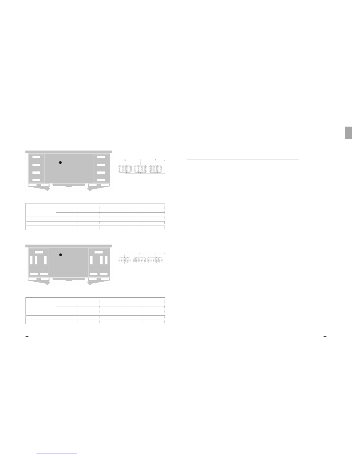
DFX DFB DFN DFC Ø 560 mm 04 RR
DFX DFB DFN DFC Ø 560 mm 06 RR
SUPPLY LINE ~3 400V 50-60HZ
STAR CONNECTION WITH NEUTRAL
SUPPLY LINE ~3 400V 50-60HZ
STAR CONNECTION WITH NEUTRAL
HTH1 HTH2
HTL1 HTL3
HTL2 HTL4
HTL5 HTL7HTL6 HTL8
HTH1 HTH4
HTH2 HTH5
HTH3 HTH6
HTL1 HTL2
HTL3 HTL5HTL4 HTL6
PE
PE
Coil power
Drip tray power
Total power
3400
1700
5100
6800
3400
10200
10200
5100
15300
13600
6800
20400
156 45 04
156 70 04
156 10 04
256 45 04
256 70 04
256 10 04
356 45 04
356 70 04
356 10 04
456 45 04
456 70 04
456 10 04
MODELS
DFX DFB DFN DFC
(W)
(W)
(W)
HTH = High power electric heater (*) HTL = Low power electric heater (*)
(*) The HTH High power heater has twice the power of the low power heater HTL
Coil power
Drip tray power
Total power
5950
1700
7650
11900
3400
15300
17850
5100
22950
23800
6800
30600
156 45 06
156 70 06
156 10 06
256 45 06
256 70 06
256 10 06
356 45 06
356 70 06
356 10 06
456 45 06
456 70 06
456 10 06
MODELS
DFX DFB DFN DFC
(W)
(W)
(W)
HTH = High power electric heater (*) HTL = Low power electric heater (*)
(*) The HTH High power heater has twice the power of the low power heater HTL
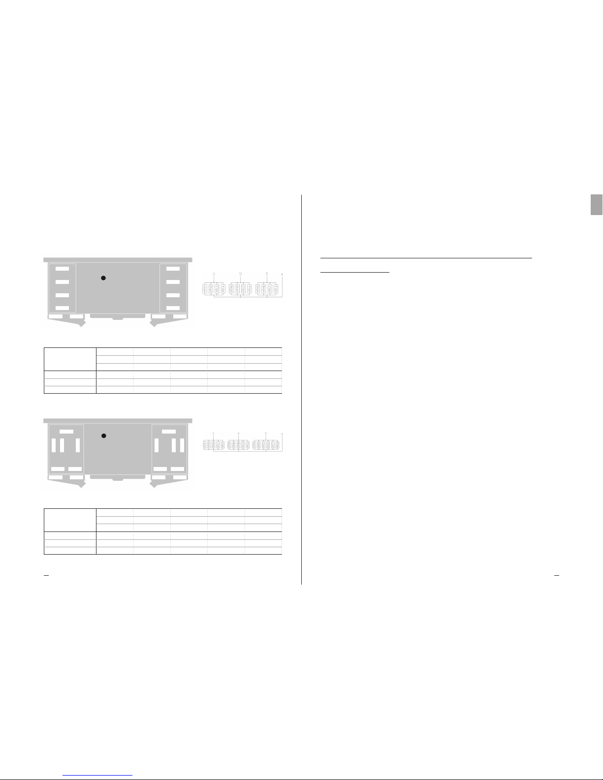
DFX DFB DFN DFC Ø 630 mm 04 RR
SUPPLY LINE ~3 400V 50-60HZ
STAR CONNECTION WITH NEUTRAL
SUPPLY LINE ~3 400V 50-60HZ
STAR CONNECTION WITH NEUTRAL
Coil power
Drip tray power
Total power
8500
1700
10200
17000
3400
20400
25500
5100
30600
34000
6800
40800
156 45 08
156 70 08
156 10 08
256 45 08
256 70 08
256 10 08
356 45 08
356 70 08
356 10 08
456 45 08
456 70 08
456 10 08
MODELS
DFX DFB DFN DFC
(W)
(W)
(W)
HTH = High power electric heater (*) HTL = Low power electric heater (*)
(*) The HTH High power heater has twice the power of the low power heater HTL
HTH = High power electric heater (*) HTL = Low power electric heater (*)
(*) The HTH High power heater has twice the power of the low power heater HTL
DFX DFB DFN DFC Ø 560 mm 08 RR
HTH1 HTH5
HTL2 HTL4
HTH2 HTH6
HTH3
HTL3
HTH4
HTH7
HTL1
HTH8
HTL5 HTL7HTL6 HTL8
PE
HTH1
HTL2
HTL1
HTH2
HTL4
HTL3
HTL5 HTL7HTL6 HTL8
PE
Coil power
Drip tray power
Total power
3680
1840
5520
7360
3680
11040
11040
5520
16560
14720
7360
22080
18400
9200
27600
163 45 04
163 70 04
163 10 04
263 45 04
263 70 04
263 10 04
363 45 04
363 70 04
363 10 04
463 45 04
463 70 04
463 10 04
563 45 04
563 70 04
563 10 04
MODELS
DFX DFB DFN DFC
(W)
(W)
(W)
Heat Exchange SolutionsThermoKey Technical Manual TC Instruction and technical data
2019
EN
MT TC A DF EN 04 2017MT TC A DF EN 04 2017
DFX DFB DFN DFC Ø 630 mm 06 RR
DFX DFB DFN DFC Ø 630 mm 08 RR
HTH = High power electric heater (*) HTL = Low power electric heater (*)
(*) The HTH High power heater has twice the power of the low power heater HTL
HTH = High power electric heater (*) HTL = Low power electric heater (*)
(*) The HTH High power heater has twice the power of the low power heater HTL
Coil power
Drip tray power
Total power
9200
1840
11040
18400
3680
22080
27600
5520
33120
36800
7360
44160
46000
9200
55200
163 45 08
163 70 08
163 10 08
263 45 08
263 70 08
263 10 08
363 45 08
363 70 08
363 10 08
463 45 08
463 70 08
463 10 08
563 45 08
563 70 08
563 10 08
MODELS
DFX DFB DFN DFC
(W)
(W)
(W)
Coil power
Drip tray power
Total power
6440
1840
8280
12880
3680
16560
19320
5520
24840
25760
7360
33120
32200
9200
41400
163 45 06
163 70 06
163 10 06
263 45 06
263 70 06
263 10 06
363 45 06
363 70 06
363 10 06
463 45 06
463 70 06
463 10 06
563 45 06
563 70 06
563 10 06
MODELS
DFX DFB DFN DFC
(W)
(W)
(W)
HTH1 HTH5
HTL2 HTL4
HTH2 HTH6
HTH3
HTL3
HTH4
HTH7
HTL1
HTH8
HTL5 HTL7HTL6 HTL8
PE
HTH1 HTH4
HTH2 HTH5
HTH3 HTH6
HTL1 HTL2
HTL3 HTL5HTL4 HTL6
PE
SUPPLY LINE ~3 400V 50-60HZ
STAR CONNECTION WITH NEUTRAL
SUPPLY LINE ~3 400V 50-60HZ
STAR CONNECTION WITH NEUTRAL
TC 9. Wiring and absorption diagrams
of fanmotors
TC 9.1
The casing of each unit is equipped with a ground terminal (PE9) with an identification label. It is mandatory to
connect the ground terminal of the unit to the external conductor or protective earthing system.
TC 9.2
In the units with wired fanmotors it is mandatory to connect the protective conductors of the fanmotors to the external
conductor or protective earthing system.
TC 9.3
It is mandatory to use protection systems against electric shock and equipment protection devices on the supply
lines of the fanmotors. The fanmotors are equipped with thermal contacts normal closed inserted in the windings
of the motor. Connect the thermal contacts to protect the engine from overheating. Please be aware that an overtemperature can also be not directly caused by an overcurrent.
Please be aware that the thermal contact closes itself when the temperature decreases without a manual reset.
TC 9.4
Strictly follow the wiring diagrams to avoid damaging the motors (a,b,c,d,e).
TC 9.5
For models fitted with non standard fanmotors please refer to the diagrams and absorptions indicated in the
supplementary sheets and the rating plate.
TC 9.6
Before using any fanmotor speed control system check its compatibility with the fanmotors. Non-compatible systems
may generate noise and damages. The Manufacturer does not accept any responsibility regarding the performance of
the units equipped with speed controllers not defined during the offer.
Heat Exchange SolutionsThermoKey Technical Manual TC Instruction and technical data
2221
EN
MT TC A DF EN 04 2017MT TC A DF EN 04 2017
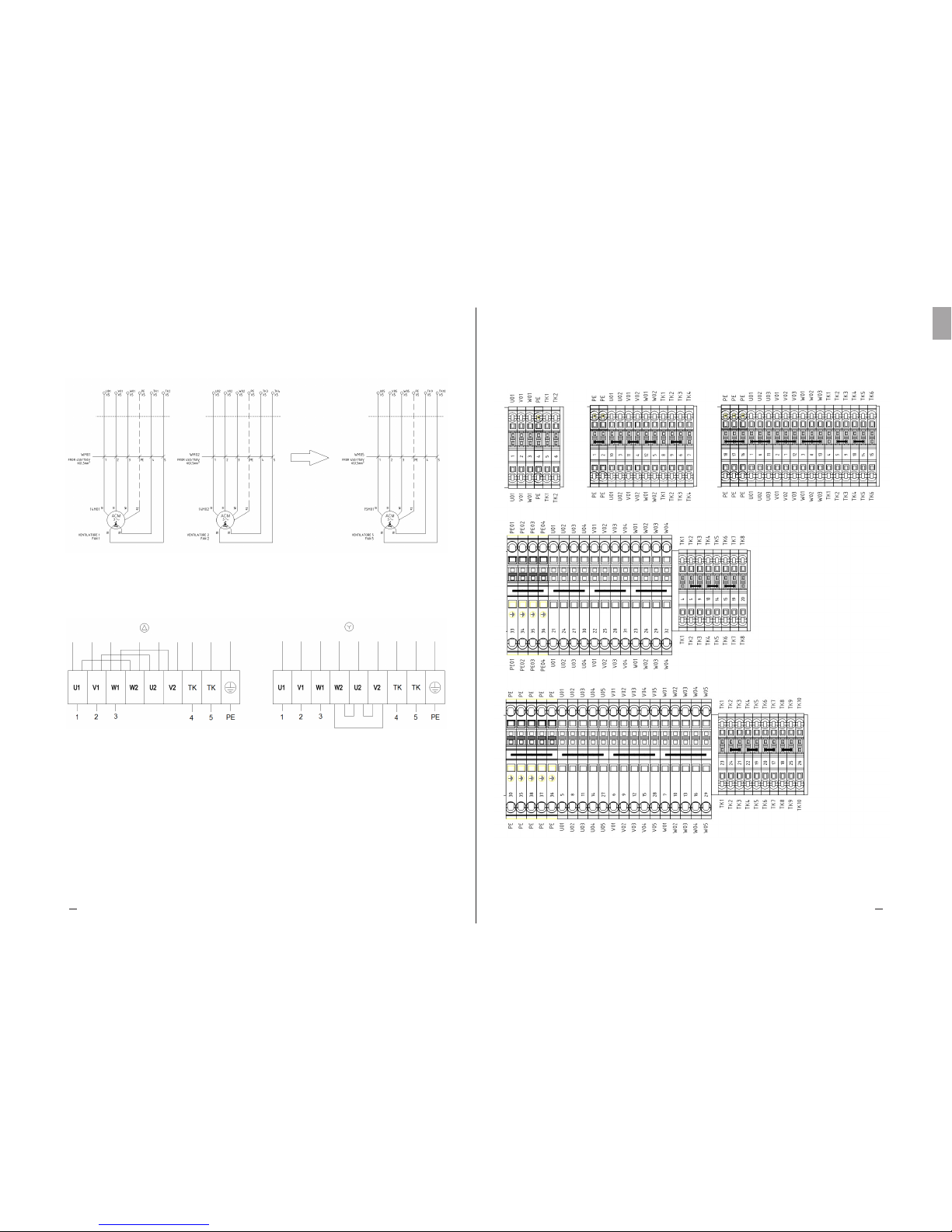
a) Standard fanmotor connection schemes
b) Fanmotor Delta connection (high speed) c) Fanmotor Star connection (low speed)
d) Terminal blocks scheme of the main electrical box from 1 up to 5 fanmotors.
Supply parallel connected and thermal contacts series connected (ready to use).
Single connection available with jumper removing.
547
250 250
577
1004 FIXING
1511
547
250 250
577
2004 FIXING
2511
547
250 250
577
3004
2002 FIXING
1002 FIXING
3511
Heat Exchange SolutionsThermoKey Technical Manual TC Instruction and technical data
2423
EN
MT TC A DF EN 04 2017MT TC A DF EN 04 2017
1
2
3
4
1
2
3
4
1
2
3
4
5
500
500
500
500
560
560
560
560
630
630
630
630
630
NO. OF
MOTORS
NOMINAL
DIAMETER
0,77
1,54
2,31
3,08
1,05
2,10
3,15
4,20
1,25
2,50
3,75
5,00
6,25
1,7
3,4
5,1
6,8
2,2
4,4
6,6
8,8
2,48
4,96
7,44
9,92
12,4
HIGH SPEED
KW A
0,49
0,98
1,47
1,96
0,58
1,16
1,74
2,32
0,84
1,68
2,52
3,36
4,20
0,84
1,68
2,52
3,36
1,1
2,2
3,3
4,4
1,42
2,84
4,26
5,68
7,10
KW A
LOW SPEED
e) standard fanmotor nominal absorptions
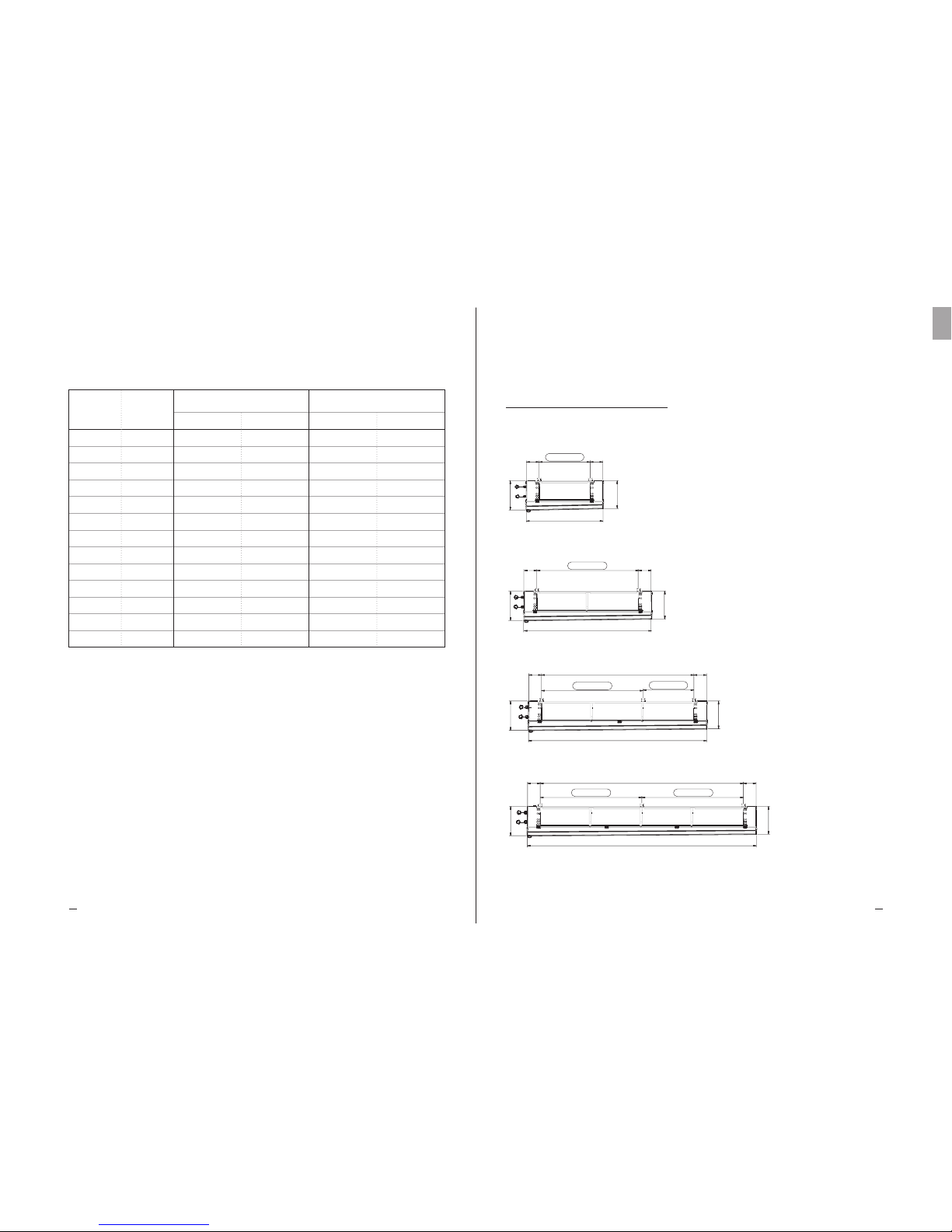
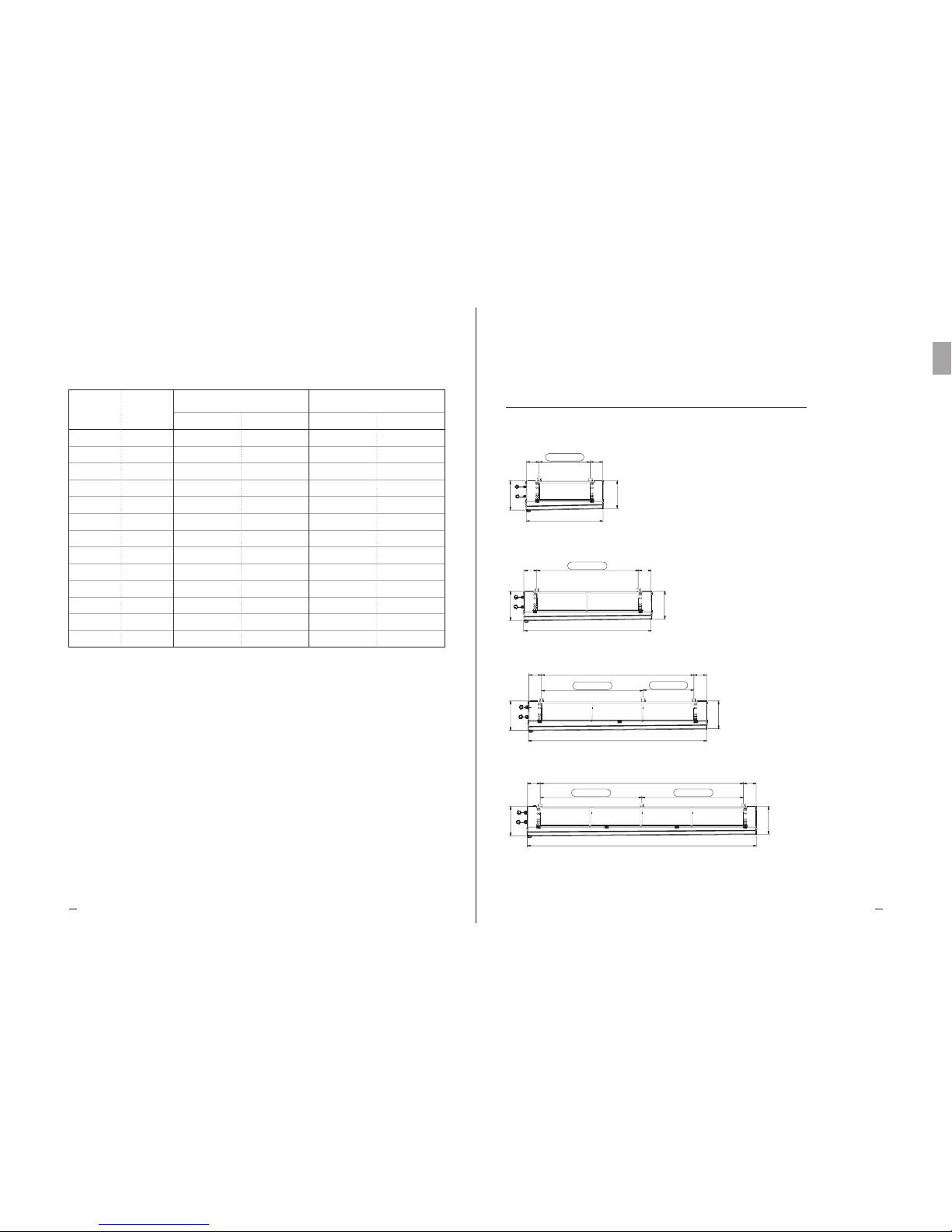
TC 10. Dimensions
DFX DFB DFN DFC Ø 500 mm
1X500
2X500
3X500
4X500
547
4004250 250
577
4511
2002 FIXING2002 FIXING
776
748
300 300
1004 FIXING
1611
776
748
2004300 300
1002 FIXING 1002 FIXING
2611
776
748
3004300 300
1002 FIXING 1000 FIXING 1002 FIXING
3612
776
748
4004300 300
1002 FIXING 1000 FIXING 1000 FIXING 1002 FIXING
4612
804
767
2404300 300
1202 FIXING 1202 FIXING
3013
Heat Exchange SolutionsThermoKey Technical Manual TC Instruction and technical data
2625
EN
MT TC A DF EN 04 2017MT TC A DF EN 04 2017
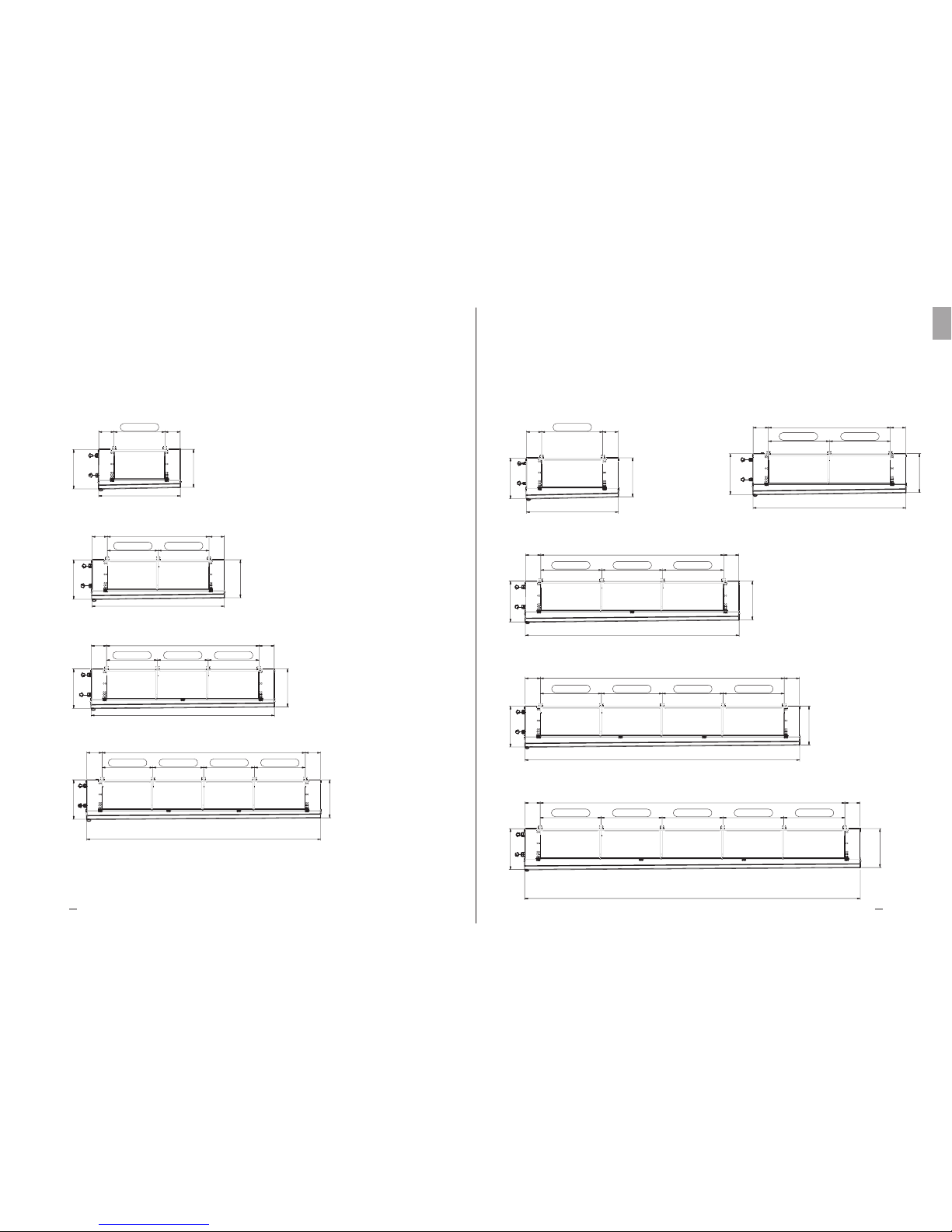
DFX DFB DFN DFC Ø 560 mm
1X560
2X560
3X560
4X560
DFX DFB DFN DFC Ø 630 mm
804
767
300 300
1204 FIXING
1812
1X630 2X630
804
767
3604300 300
1202 FIXING 1200 FIXING 1202 FIXING
4212
3X630
804
767
4804300 300
1202 FIXING 1200 FIXING 1200 FIXING 1202 FIXING
5412
4X630
804
767
6004 300 300
1202 FIXING 1200 FIXING 1200 FIXING 1200 FIXING 1202 FIXING
6613
5X630

1810
449
1656
50
661
1746 FIXING
1960
1896 FIXING
50
863
470
1808
1960
1896 FIXING
50
886
470
1808
Heat Exchange SolutionsThermoKey Technical Manual TC Instruction and technical data
2827
EN
MT TC A DF EN 04 2017MT TC A DF EN 04 2017
DFX DFB DFN DFC
Ø 500 mm
Ø 560 mm
Ø 630 mm
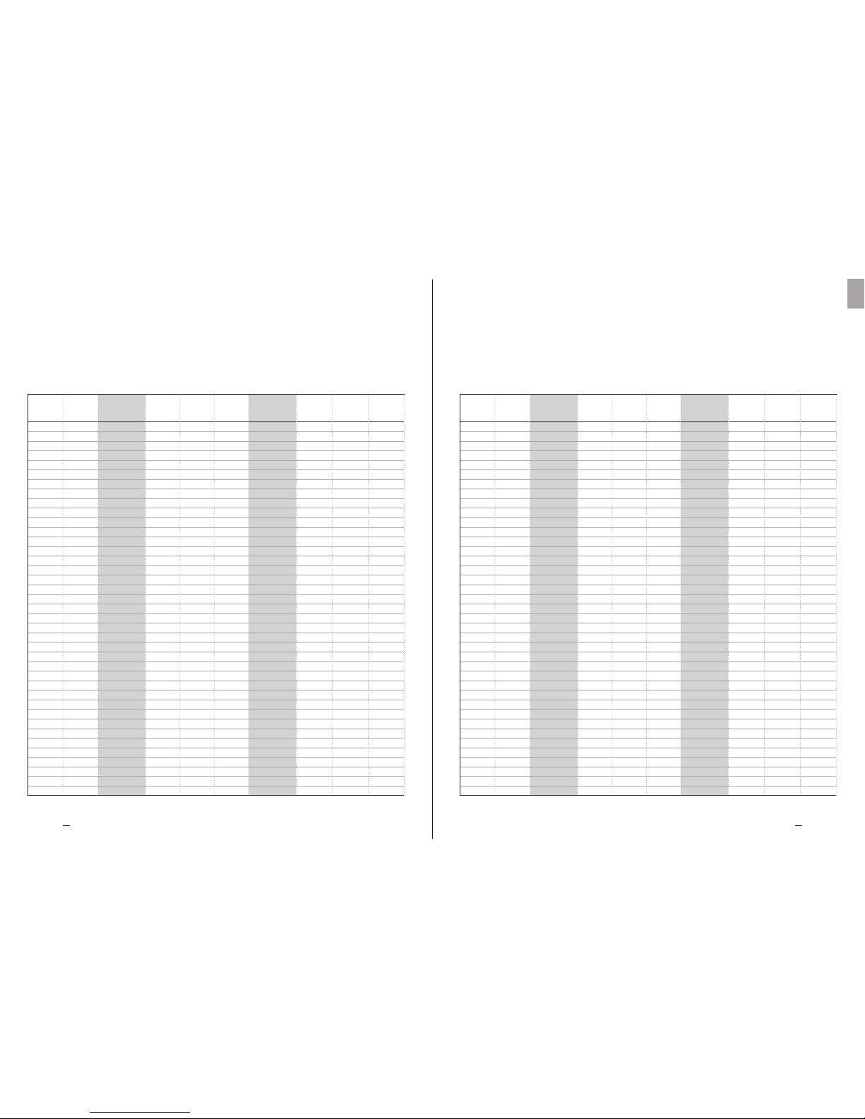
TC 11. Technical Data
1
1
1
2
2
2
3
3
3
4
4
4
1
1
1
2
2
2
3
3
3
4
4
4
1
1
1
2
2
2
3
3
3
4
4
4
5
5
5
500
500
500
500
500
500
500
500
500
500
500
500
560
560
560
560
560
560
560
560
560
560
560
560
560
630
630
630
630
630
630
630
630
630
630
630
630
630
630
60,57
90,85
121,40
121,14
181,70
242,80
181,71
272,55
364,20
242,28
363,40
485,60
90,85
136,28
181,71
181,70
272,56
363,42
272,55
408,84
545,13
363,40
545,12
726,84
109,02
163,54
218,05
218,04
327,08
436,10
327,06
490,62
654,15
436,08
654,16
872,20
/
/
/
7,2
10,7
14,3
14,4
21,4
28,6
21,6
32,1
42,9
28,8
42,8
57,2
10,9
16,3
21,7
21,8
32,6
43,4
32,7
48,9
65,1
43,6
65,2
86,8
12,9
19,3
25,8
25,8
38,6
51,6
38,7
57,9
77,4
51,6
77,2
103,2
/
/
/
58,76
88,15
117,53
117,52
176,30
235,06
176,28
264,45
352,59
235,04
352,60
470,12
88,15
132,22
176,29
176,30
264,44
352,58
264,45
396,66
528,87
352,60
528,88
705,16
105,77
158,66
211,55
211,54
317,32
423,10
317,31
475,98
634,65
423,08
634,64
846,20
528,85
793,30
1057,75
12,7
19,1
25,4
25,4
38,2
50,8
38,1
57,3
76,2
50,8
76,4
101,6
19,1
28,6
38,1
38,2
57,2
76,2
57,3
85,8
114,3
76,4
114,3
76,4
114,4
152,4
22,9
34,3
45,7
45,8
68,6
91,4
68,7
102,9
137,2
182,8
114,5
171,5
228,5
104
118
131
190
216
241
274
312
352
358
409
462
148
168
198
257
297
348
361
425
488
467
553
632
169
192
226
287
333
392
401
474
546
516
615
705
638
770
875
104
118
131
190
216
241
274
312
352
358
409
462
148
168
198
257
297
348
361
425
488
467
553
632
169
192
226
287
333
392
401
474
546
516
615
705
/
/
/
DFX1504504
DFX1504506
DFX1504508
DFX2504504
DFX2504506
DFX2504508
DFX3504504
DFX3504506
DFX3504508
DFX4504504
DFX4504506
DFX4504508
DFX1564504
DFX1564506
DFX1564508
DFX2564504
DFX2564506
DFX2564508
DFX3564504
DFX3564506
DFX3564508
DFX4564504
DFX4564506
DFX4564508
DFX1634504
DFX1634506
DFX1634508
DFX2634504
DFX2634506
DFX2634508
DFX3634504
DFX3634506
DFX3634508
DFX4634504
DFX4634506
DFX4634508
/
/
/
DFB1504504
DFB1504506
DFB1504508
DFB2504504
DFB2504506
DFB2504508
DFB3504504
DFB3504506
DFB3504508
DFB4504504
DFB4504506
DFB4504508
DFB1564504
DFB1564506
DFB1564508
DFB2564504
DFB2564506
DFB2564508
DFB3564504
DFB3564506
DFB3564508
DFB4564504
DFB4564506
DFB4564508
DFB1634504
DFB1634506
DFB1634508
DFB2634504
DFB2634506
DFB2634508
DFB3634504
DFB3634506
DFB3634508
DFB4634504
DFB4634506
DFB4634508
DFB5634504
DFB5634506
DFB5634508
Mot.n°Dia
[mm]
MODEL
External
Surface
[m2]
External
Surface
[m2]
Internal
Volume
[dm3]
Internal
Volume
[dm3]
Net
Weight
[kg]
Net
Weight
[kg]
MODEL
DFX DFB PITCH 4,5 mm
32
70
18x30
32
70
18x30
32
70
18X30
Heat Exchange SolutionsThermoKey Technical Manual TC Instruction and technical data
3029
EN
MT TC A DF EN 04 2017MT TC A DF EN 04 2017
DFX DFB PITCH 10,0 mmDFX DFB PITCH 7,0 mm
1
1
1
2
2
2
3
3
3
4
4
4
1
1
1
2
2
2
3
3
3
4
4
4
1
1
1
2
2
2
3
3
3
4
4
4
5
5
5
500
500
500
500
500
500
500
500
500
500
500
500
560
560
560
560
560
560
560
560
560
560
560
560
560
630
630
630
630
630
630
630
630
630
630
630
630
630
630
DFX1507004
DFX1507006
DFX1507008
DFX2507004
DFX2507006
DFX2507008
DFX3507004
DFX3507006
DFX3507008
DFX4507004
DFX4507006
DFX4507008
DFX1567004
DFX1567006
DFX1567008
DFX2567004
DFX2567006
DFX2567008
DFX3567004
DFX3567006
DFX3567008
DFX4567004
DFX4567006
DFX4567008
DFX1637004
DFX1637006
DFX1637008
DFX2637004
DFX2637006
DFX2637008
DFX3637004
DFX3637006
DFX3637008
DFX4637004
DFX4637006
DFX4637008
/
/
/
39,84
59,76
79,68
79,68
119,52
159,36
119,52
179,28
239,04
159,36
239,04
318,72
59,76
89,64
119,53
119,52
179,28
239,06
179,28
268,92
358,59
239,04
358,56
478,12
71,72
107,57
143,43
143,44
215,14
286,86
215,16
322,71
430,29
286,88
430,28
573,72
/
/
/
7,2
10,7
14,3
14,4
21,4
28,6
21,6
32,1
42,9
28,8
42,8
57,2
10,9
16,3
21,7
21,8
32,6
43,4
32,7
48,9
65,1
43,6
65,2
86,8
12,9
19,3
25,8
25,8
38,6
51,6
38,7
57,9
77,4
51,6
77,2
103,2
/
/
/
102
115
127
186
210
234
268
304
341
351
399
448
144
164
192
248
289
331
352
412
470
455
537
609
165
187
219
277
323
372
390
460
526
502
596
679
/
/
/
38,97
58,45
77,94
77,94
116,90
155,88
116,91
175,35
233,82
155,88
233,80
311,76
58,45
87,68
116,91
116,90
175,36
233,82
175,35
263,04
350,73
233,80
350,72
467,64
70,14
105,22
140,29
140,28
210,44
280,58
210,42
315,66
420,87
280,56
420,88
561,16
350,70
526,10
701,45
102
115
127
186
210
234
268
304
341
351
399
448
144
164
192
248
289
331
352
412
470
455
537
609
165
187
219
277
323
372
390
460
526
502
596
679
620
746
842
DFB1507004
DFB1507006
DFB1507008
DFB2507004
DFB2507006
DFB2507008
DFB3507004
DFB3507006
DFB3507008
DFB4507004
DFB4507006
DFB4507008
DFB1567004
DFB1567006
DFB1567008
DFB2567004
DFB2567006
DFB2567008
DFB3567004
DFB3567006
DFB3567008
DFB4567004
DFB4567006
DFB4567008
DFB1637004
DFB1637006
DFB1637008
DFB2637004
DFB2637006
DFB2637008
DFB3637004
DFB3637006
DFB3637008
DFB4637004
DFB4637006
DFB4637008
DFB5637004
DFB5637006
DFB5637008
Mot.n°Dia
[mm]
MODEL
1
1
1
2
2
2
3
3
3
4
4
4
1
1
1
2
2
2
3
3
3
4
4
4
1
1
1
2
2
2
3
3
3
4
4
4
5
5
5
500
500
500
500
500
500
500
500
500
500
500
500
560
560
560
560
560
560
560
560
560
560
560
560
560
630
630
630
630
630
630
630
630
630
630
630
630
630
630
DFX1501004
DFX1501006
DFX1501008
DFX2501004
DFX2501006
DFX2501008
DFX3501004
DFX3501006
DFX3501008
DFX4501004
DFX4501006
DFX1001008
DFX1561004
DFX1561006
DFX1561008
DFX2561004
DFX2561006
DFX2561008
DFX3561004
DFX3561006
DFX3561008
DFX4561004
DFX4561006
DFX4561008
DFX1631004
DFX1631006
DFX1631008
DFX2631004
DFX2631006
DFX2631008
DFX3631004
DFX3631006
DFX3631008
DFX4631004
DFX4631006
DFX4631008
/
/
/
28,65
42,97
57,30
57,30
85,94
114,60
85,95
128,91
171,90
114,60
171,88
229,20
42,97
64,46
85,95
85,94
128,92
171,90
128,91
193,38
257,85
171,88
257,84
343,80
51,57
77,35
103,14
103,14
154,70
206,28
154,71
232,05
309,42
206,28
309,40
412,56
/
/
/
7,2
10,7
14,3
14,4
21,4
28,6
21,6
32,1
42,9
28,8
42,8
57,2
10,9
16,3
21,7
21,8
32,6
43,4
32,7
48,9
65,1
43,6
65,2
86,8
12,9
19,3
25,8
25,8
38,6
51,6
38,7
57,9
77,4
51,6
77,2
103,2
/
/
/
101
113
125
184
206
229
264
298
333
347
391
437
142
160
187
243
281
322
344
402
457
446
524
593
162
183
214
272
315
362
382
449
511
492
581
660
/
/
/
28,28
42,42
56,56
56,56
84,84
113,12
84,84
127,26
169,68
113,12
169,68
226,24
42,42
63,63
84,84
84,84
127,26
169,68
127,26
190,89
254,52
169,68
254,52
339,36
50,90
76,35
101,81
101,80
152,70
203,62
152,70
229,05
305,43
203,60
305,40
407,24
254,50
381,75
509,05
12,7
19,1
25,4
25,4
38,2
50,8
38,1
57,3
76,2
50,8
76,4
101,6
19,1
28,6
38,1
38,2
57,2
76,2
57,3
85,8
114,3
76,4
114,4
152,4
22,9
34,3
45,7
45,8
68,6
91,4
68,7
102,9
137,2
91,6
137,2
182,8
114,5
171,5
228,5
12,7
19,1
25,4
25,4
38,2
50,8
38,1
57,3
76,2
50,8
76,4
101,6
19,1
28,6
38,1
38,2
57,2
76,2
57,3
85,8
114,3
76,4
114,4
152,4
22,9
34,3
45,7
45,8
68,6
91,4
68,7
102,9
137,2
91,6
137,2
182,8
114,5
171,5
228,5
101
113
125
184
206
229
264
298
333
347
391
437
142
160
187
243
281
322
344
402
457
446
524
593
162
183
214
272
315
362
382
449
511
492
581
660
607
727
817
DFB1501004
DFB1501006
DFB1501008
DFB2501004
DFB2501006
DFB2501008
DFB3501004
DFB3501006
DFB3501008
DFB4501004
DFB4501006
DFB1001008
DFB1561004
DFB1561006
DFB1561008
DFB2561004
DFB2561006
DFB2561008
DFB3561004
DFB3561006
DFB3561008
DFB4561004
DFB4561006
DFB4561008
DFB1631004
DFB1631006
DFB1631008
DFB2631004
DFB2631006
DFB2631008
DFB3631004
DFB3631006
DFB3631008
DFB4631004
DFB4631006
DFB4631008
DFB5631004
DFB5631006
DFB5631008
Mot.n°Dia
[mm]
MODEL
External
Surface
[m2]
External
Surface
[m2]
Internal
Volume
[dm3]
Internal
Volume
[dm3]
Net
Weight
[kg]
Net
Weight
[kg]
MODEL
External
Surface
[m2]
External
Surface
[m2]
Internal
Volume
[dm3]
Internal
Volume
[dm3]
Net
Weight
[kg]
Net
Weight
[kg]
MODEL
IT
MT TC A DF IT 04 2017
Manuale tecnico – TC
Serie DFX, DFB, DFN, DFC
Aeroevaporatori e aerorefrigeratori
industriali a doppio flusso
LA VERSIONE ORIGINALE DELLE PRESENTI ISTRUZIONI
È IN LINGUA ITALIANA
MT TC A DF IT 04 2017
Heat Exchange SolutionsThermoKey Manuale Tecnico TC Istruzioni e dati tecnici
3332
IT
MT TC A DF IT 04 2017MT TC A DF IT 04 2017
LEGGERE ATTENTAMENTE E COMPRENDERE COMPLETAMENTE TUTTE
LE INFORMAZIONI CONTENUTE IN QUESTE ISTRUZIONI PRIMA DELLA
PROGETTAZIONE ED IN OGNI CASO PRIMA DI EFFETTUARE QUALUNQUE
OPERAZIONE DI MOVIMENTAZIONE, DISIMBALLAGGIO, MONTAGGIO,
POSIZIONAMENTO E MESSA IN ESERCIZIO DELL’APPARECCHIO.
IL COSTRUTTORE DECLINA OGNI RESPONSABILITÀ PER DANNI A PERSONE
O COSE DERIVANTI DALLA MANCATA OSSERVANZA DELLE INDICAZIONI
CONTENUTE NEL PRESENTE DOCUMENTO.
L’originale del presente manuale è in italiano , ed è reperibile sul sito internet: www.thermokey.com.
La traduzione in inglese è conforme all’originale ed è reperibile sul sito internet: www.thermokey.com.
Le traduzioni in altre lingue possono contenere errori; in caso di dubbio fare sempre riferimento
alla versione originale in italiano od alla sua traduzione in inglese.
Il sistema di gestione Qualità della ThermoKey è certificato in conformità alla norma ISO 9001,
il Sistema di Gestione Ambiente è certificato in conformità alla norma ISO 14001 e il Sistema di
Gestione Sicurezza è certificato in conformità alla norma OHSAS 18001.
Dual Flow
Industrial Unit Cooler
TC 1. RIFERIMENTI NORMATIVI
TC 2. PERICOLI
TC 3. AVVERTENZE
TC 4. DESTINAZIONE D’USO
TC 5. ISPEZIONE, MOVIMENTAZIONE E TRASPORTO
TC 6. INSTALLAZIONE E MESSA IN OPERA
TC 7. MANUTENZIONE GENERALE E CONTROLLO
TC 8. SCHEMI DI COLLEGAMENTO DELLE RESISTENZE DI SBRINAMENTO
TC 9. SCHEMI DI COLLEGAMENTO DEI MOTOVENTILATORI
TC 10. CARATTERISTICHE DIMENSIONALI
TC 11. DATI TECNICI
INDICE
34
34
35
36
36
37
40
42
46
51
55
Heat Exchange SolutionsThermoKey Manuale Tecnico TC Istruzioni e dati tecnici
3534
IT
MT TC A DF IT 04 2017MT TC A DF IT 04 2017
Pericolo di elettrocuzione. Il prodotto è allestito con elettroventilatori ed eventuali resistestenze elettriche di sbrinamento
con tensione nominale di funzionamento in bassa tensione trifase e monofase. Le linee di alimentazione elettrica dovranno
utilizzare i sistemi di protezione contro la scossa elettrica e di protezione dell’equipaggiamento previsti dalla normativa
vigente.
Pericolo di ustione. Nei prodotti allestiti con resistenze elettriche di sbrinamento le temperature superficiali delle corazze,
se lasciate accese senza controllo, possono raggiungere i 350°C.
Pericolo di taglio. Lo scambiatore di calore, parte integrante del prodotto, è costituito da alette metalliche con bordi
taglienti, non protette. La carrozzeria è costituita da componenti in lamiera che in alcuni punti possono presentare bordi
taglienti non protetti.
Pericolo parti in movimento. Il prodotto è allestito con elettroventilatori dotati di griglia di protezione secondo
quanto previsto dalla normativa vigente. Per alcuni prodotti potrebbe essere possibile accedere volutamente alle parti
in movimento (pale dei motoventilatori) da zone non protette. Prima di qualsiasi accesso assicurarsi che le parti
in movimento non possano costituire pericolo agli operatori.
Pericolo di schiacciamento degli arti o della persona. Durante le fasi di movimentazione, trasporto ed installazione,
funzionamento e manutenzione, porre la massima attenzione al peso indicato di ogni prodotto per evitare ribaltamenti
o cadute pericolose verso gli operatori.
Pericolo di caduta oggetti. I prodotti sono provvisti di porte, vaschette o lamierati di tamponamento che in fase di
installazione o di manutenzione possono essere smontate rimuovendo le viti di fissaggio previste, prendere le opportune
precauzioni.
TC 2. Pericoli
TC 1. Riferimenti Normativi
Il prodotto descritto in questo manuale risulta conforme alla:
DIRETTIVA MACCHINE 2006/42/EC
DIRETTIVA BASSA TENSIONE 2014/35/EU
DIRETTIVA COMPATIBILITA' ELETTROMAGNETICA 2014/30/EU
DIRETTIVA PED 2014/68/EU
DIRETTIVA ErP 2009/125/EC
TC 3. Avvertenze
TC 3.1
Contenuto del Manuale Tecnico di prodotto:
ISTRUZIONI GENERALI PER UN USO SICURO (IG)
ISTRUZIONI PER LA MOVIMENTAZIONE ED IL DISIMBALLO (IM)
ISTRUZIONI E DATI TECNICI (TC)
ISTRUZIONI SPECIFICHE D’USO E MANUTENZIONE (IS)
TC 3.2
Questo manuale è la sezione TC denominata ISTRUZIONI E DATI TECNICI del Manuale Tecnico di prodotto.
Per qualsiasi informazione non contemplata nel presente manuale fare riferimento alle altre sezioni (IG–IM–IS) e in
caso di dubbio contattare il Costruttore.
TC 3.3
Questo manuale è parte integrante dei modelli DFX DFB DFN e DFC e come tale deve essere conservato per tutto il
periodo di vita del prodotto.
TC 3.4
Eventuale documentazione tecnica supplementare relativa ai prodotti non standard è allegata al presente manuale, è
integrante ed è codificata con codice specifico indicato sui documenti di spedizione.
TC 3.5
Il prodotto descritto in questo manuale è considerato una quasi-macchina quindi non utilizzabile così come fornito
ma è un componente per impianti di condizionamento o refrigerazione e deve essere installato e messo in servizio solo
da operatori qualificati (vedere capitolo relativo ad installazione e messa in opera).
TC 3.6
Ogni prodotto è corredato di Dichiarazione di Incorporazione CE.
TC 3.7
Ulteriore documentazione relativa al prodotto, costituita da cataloghi, guide e bollettini tecnici, è fornita
direttamente da Thermokey reperibile sul sito internet www.thermokey.com.
CATALOGHI – http://www.thermokey.com/Cataloghi.aspx
MANUALI – http://www.thermokey.com/Manuali.aspx
Heat Exchange SolutionsThermoKey Manuale Tecnico TC Istruzioni e dati tecnici
3736
IT
MT TC A DF IT 04 2017MT TC A DF IT 04 2017
TC 4. Destinazione d'uso
TC 4.1
Il modello deve essere utilizzato esclusivamente per lo scopo di seguito indicato altrimenti, l’uso è da considerarsi
improprio ed esonera il costruttore da qualsiasi responsabilità conseguente.
TC 4.2
Gli aeroevaporatori o aerorefrigeratori industriali della serie DFX DFB DFN e DFC sono progettati per essere utilizzati in
tutti i settori alimentari, nelle medie e grandi celle frigorifere o magazzini refrigerati, per la conservazione del prodotto
fresco e congelato e anche per il rarescamento e condizionamento di medie e grandi sale di lavorazione. Tutte le unità
standard sono equipaggiate con gruppo ventilante ad alta ecienza per un'ottimale distribuzione dell’aria.
TC 4.3
Il modello standard è equipaggiato con motoventilatori non adatti a sopportare prevalenze statiche aggiuntive come
quelle dovute a canalizzazioni, tunnel di abbattimento, etc..
TC 4.4
In caso di dubbio sulla destinazione d'uso contattare il Costruttore.
TC 5. Ispezione, movimentazione e trasporto
TC 5.1
Al ricevimento del modello controllare lo stato di integrità dell'imballaggio e del prodotto; contestare subito al
trasportatore qualsiasi danno eventuale verificatosi. L’imballaggio è fabbricato conformemente al modello, agli
adeguati mezzi di trasporto e di movimentazione.
TC 5.2
Durante il trasporto e la movimentazione del modello nel suo imballaggio, evitare sollecitazioni non conformi
e improprie sul prodotto imballato, attenersi a tutte le indicazioni illustrate e mantenere il modello sempre nella
posizione indicata in figura (Fig.1).
TC 5.3
Durante il trasporto e la movimentazione del prodotto imballato, utilizzare apposite protezioni per evitare di ferirsi
con le parti dell’imballaggio come chiodi, tavole o cartone e le parti del modello come le alette o la carrozzeria (vedi
DPI manuale tecnico sezione I cap IG 6).
TC 5.4
Disimballare il modello il più vicino possibile al luogo di installazione (vedi anche installazione e messa in opera). In
generale il modello non deve essere trasportato o movimentato privo dell’imballaggio originale.
TC 5.5
Durante la movimentazione per l'installazione del modello disimballato, utilizzare apposite protezioni per evitare di ferirsi
con le parti taglienti come le alette o la carrozzeria (vedi DPI manuale tecnico sezione I cap IG 6).
TC 6.1
L’installazione e la messa in opera del modello deve essere eseguita da personale esperto e qualificato. Per il fissaggio
seguire lo schema indicato in figura (Fig.2).
TC 6.2
Per una corretta circolazione dell’aria verificare che nell’ambiente di installazione siano garantiti volumi liberi e
passaggi dell’aria adeguati e conformi alle caratteristiche di portata e freccia d’aria del modello. Altrimenti potrebbero
non essere garantite le prestazioni dichiarate e generarsi difettosità di funzionamento. Attenzione a non ostruire né
l’aspirazione né la mandata dei motoventilatori e dello scambiatore (Fig.3).
TC 6.3
Verificare che le strutture di supporto e gli ancoraggi siano conformi al peso ed alla forma del modello (vedi capitoli
Caratteristiche dimensionali e Dati tecnici).
TC 6.4
Fissare il modello a tutti i punti previsti (vedi capitolo Caratteristiche dimensionali) con ancoraggi adeguati e conformi
al peso complessivo (peso netto del modello, peso del refrigerante, peso dell’eventuale accumulo di ghiaccio sullo
scambiatore, peso dell’eventuale accumulo nelle vaschette di raccolta condensa).
TC 6.5
Il modello non è progettato per supportare carichi aggiuntivi.
TC 6.6
Nei modelli con sbrinamento elettrico verificare che sia garantito o predisporre lo spazio adeguato per permettere la
sostituzione delle resistenze infilate negli scambiatori.
fig.1 - Per una movimentazione sicura le forche
devono sempre sporgere dall'imballaggio.
TC 6. Installazione e messa in opera

Heat Exchange SolutionsThermoKey Manuale Tecnico TC Istruzioni e dati tecnici
3938
IT
MT TC A DF IT 04 2017MT TC A DF IT 04 2017
TC 6.7
Negli ambienti con più unità installate non si devono effettuare sbrinamenti alternati per evitare la formazione
anomala di brina sugli scambiatori.
TC 6.8
Verificare che la linea di alimentazione elettrica sia conforme alle caratteristiche del modello indicate sui dati di targa.
TC 6.9
Prima di collegare il modello verificare che siano stati utilizzati i dispositivi di sezionamento ed interruzione dalla rete
di alimentazione, di protezione contro la scossa elettrica, di protezione dell’equipaggiamento e quant’altro previsto dalla
normativa vigente. I modelli standard sono forniti con scatole di derivazione per l’alimentazione dei motoventilatori e
con scatole di derivazione per l’alimentazione delle resistenze, nei modelli con sbrinamento elettrico.
TC 6.10
Se venissero utilizzati dispositivi di regolazione del numero di giri dei motoventilatori verificarne la compatibilità,
dispositivi non compatibili possono generare rumorosità e danneggiamenti ai motoventilatori; il costruttore non
garantisce le prestazioni indicate per modelli equipaggiati con dispositivi di regolazione.
TC 6.11
Verificare che la linea del refrigerante sia adeguata alle prestazioni del modello. In fase di collegamento del circuito
refrigerante non deformare i capillari e non modificare la posizione del distributore o dei collettori in genere.
TC 6.12
Verificare che le condizioni di funzionamento (umidità, temperature e pressioni) siano conformi alle caratteristiche
di selezione del prodotto.
TC 6.13
Per i modelli con sbrinamento elettrico, in funzione della tipologia di cella, definire correttamente il tempo ed il
numero dei cicli di sbrinamento. Lo sbrinamento deve essere cronotermostatato e le sonde di temperatura non devono
interrompere il ciclo di sbrinamento anzitempo ma solo una eventuale sovratemperatura, devono essere collocate
nelle zone più fredde dello scambiatore (zone con maggior formazione di brina) e a distanza dalle resistenze.
TC 6.14
Verificare che a conclusione di ogni ciclo di sbrinamento elettrico o a gas caldo o a glicole caldo il pacco alettato gli
sgocciolatoi interni e gli scarichi condensa risultino puliti. Correggere eventualmente i tempi ed il numero dei cicli
di sbrinamento. Accumuli di brina tendono a trasformarsi in accumuli di ghiaccio dannosi che possono provocare
malfunzionamento o la rottura dello scambiatore.
TC 6.15
Installare sulla linea di scarico condensa gli opportuni sifoni e verificarne l’efficacia in tutte le temperature di utilizzo.
Nelle celle a bassa temperatura o per funzionamenti sotto il punto di congelamento, l’umidità esterna che rientra dalla
linea di scarico priva di sifoni genera accumuli di ghiaccio dannosi.
TC 6.16
L’accessibilità al modello installato, per qualsiasi tipo di intervento, deve essere riservata a personale esperto e
qualificato alla conduzione dell’impianto, secondo le norme vigenti.
fig.2 – Sequenza di fissaggio:
a) rimuovere il coperchio della gabbia di legno,
b) sequenza per una possibile installazione facilitata solo per modelli standard fino ad un massimo di due motoventilatori,
rimuovere anche i fianchi e le testate della gabbia di legno,
c) sollevare e posizionare,
d) fissare il modello a tutti i punti previsti con ancoraggi adeguati e conformi al peso complessivo (peso netto del modello,
peso del refrigerante, peso dell’eventuale accumulo di ghiaccio sullo scambiatore, peso dell’eventuale accumulo nelle
vaschette di raccolta condensa),
e) rimuovere la gabbia di legno e le staffe di trasporto,
f) rimuovere il fondo della gabbia di legno e le staffe di trasporto.
c) e d)
c) e d)
a) e b)
e) f)
a)

Heat Exchange SolutionsThermoKey Manuale Tecnico TC Istruzioni e dati tecnici
4140
IT
MT TC A DF IT 04 2017MT TC A DF IT 04 2017
TC 7. Manutenzione generale e controllo
TC 7.1
Prima di effettuare qualsiasi intervento di manutenzione accertarsi che l’alimentazione elettrica del modello
sia stata sezionata: le parti elettriche potrebbero essere collegate a controlli automatici. Tutte le operazioni di
manutenzione devono essere effettuate da personale esperto e qualificato.
TC 7.2
Il modello è costituito principalmente da: uno scambiatore di calore a pacco alettato, una carrozzeria portante
in lamiera con pannellature, coperchi e vaschette di raccolta condensa apribili, da elettroventilatori e nei modelli
con sbrinamento elettrico, sono inserite nello scambiatore e fissate agli sgocciolatoi resistenze corazzate in acciaio
inossidabile, con terminali vulcanizzati e dispositivi di blocco che ne evitano lo scorrimento (vedi fig.4).
TC 7.3
Verificare periodicamente i fissaggi del modello, le connessioni elettriche e i collegamenti alla linea del refrigerante.
TC 7.4
Provvedere alla pulizia periodica della carrozzeria e dello scambiatore utilizzando detergenti idonei o eventualmente
dell’acqua e sapone con pH neutro. Non utilizzare detergenti aggressivi, solventi, soluzioni acide o basiche e contenenti
cloro o ammoniaca. Evitare l’utilizzo di abrasivi in genere. Se si dovessero utilizzare igienizzanti verificarne la
compatibilità con i materiali. In caso di dubbio contattare il Costruttore.
TC 7.5
Controllare l’efficacia dello sbrinamento. Per i modelli con sbrinamento elettrico, verificare periodicamente la
funzionalità di tutte le resistenze. Il costruttore non può rispondere in alcun modo di difettosità e danni determinati
da malfunzionamenti non rilevati (es. dannosi accumuli di ghiaccio).
fig.3 – Distanza minima dalle pareti
Attenzione a non ostruire né l'aspirazione né la mandata d'aria dei motoventilatori e dello scambiatore.
<< MIN. 1m >> << MIN. 1m >>
TC 7.6
Provvedere alla sostituzione delle resistenze elettriche non funzionanti. Prestare particolare attenzione nelle fasi di
installazione per evitare danni agli isolamenti vulcanizzati; ripristinare correttamente i collegamenti (vedi schemi
allegati) ed i sistemi di blocco per evitare la migrazione delle stesse durante il funzionamento.
TC 7.7
I periodi di verifica e manutenzione sono dipendenti dalla tipologia di cella, pertanto da definirsi da personale esperto
e qualificato.
TC 7.8
Per qualsiasi operazione sul modello, non descritta su questo manuale, contattare il Costruttore.
fig.4 – Componenti
a) i coperchi frontali sono smontabili per permettere l'accesso al vano collettori nelle fasi di installazione e manutenzione.
La chiusura è assicurata con viti.
b) i coperchi inferiori sono smontabili per garantire la completa accessibilità al vano collettori.
c) le vaschette sono dotate di cerniere per facilitare l'accesso allo sgocciolatoio per l'eventuale sostituzione delle resistenze
di sbrinamento o per le operazioni di pulizia, sono eventualmente smontabili se fosse necessaria la sostituzione.
d) i motoventilatori sono dotati di griglia di protezione portante per permettere le eventuali operazioni di sostituzione
completamente dall'esterno.
COPERCHI
INFERIORI
SMONTABILI
COPERCHI
FRONTALI
APRIBILI
VASCHETTE
APRIBILI
E SMONTABILI
MONOVENTILATORI

Heat Exchange SolutionsThermoKey Manuale Tecnico TC Istruzioni e dati tecnici
4342
IT
MT TC A DF IT 04 2017MT TC A DF IT 04 2017
TC 8. Schemi di collegamento
e potenze delle resistenze di sbrinamento
TC 8.1
Il telaio di ogni modello è dotato di un polo di terra (PE) con etichetta di identificazione.
E' obbligatorio collegare il polo di terra del modello all'impianto o al conduttore esterno di messa a terra.
TC 8.2
È obbligatorio utilizzare i sistemi di protezione contro la scossa elettrica e di protezione dell'equipaggiamento sulle
linee di alimentazione delle resistenze di sbrinamento.
TC 8.3
Verificare periodicamente la funzionalità di tutte le resistenze di sbrinamento per evitare che sui modelli si formino
accumuli di ghiaccio dannosi causati da malfunzionamenti non rilevati.
DFX DFB DFN DFC Ø 500 mm 04 RR
ALIMENTAZIONE ~3 400V 50-60HZ
COLLEGAMENTO A STELLA CON NEUTRO
Potenza batteria
Potenza sgocciolatoio
Potenza totale
3400
1700
5100
6800
3400
10200
10200
5100
15300
13600
6800
20400
150 45 04
150 70 04
150 10 04
250 45 04
250 70 04
250 10 04
350 45 04
350 70 04
350 10 04
450 45 04
450 70 04
450 10 04
MODELLI
DFX DFB DFN DFC
(W)
(W)
(W)
HTH1
HTH2
HTH3
HTH4
HTL1 HTL3HTL2 HTL4
PE
HTH = Resistenza di alta potenza (*) HTL = Resistenza di bassa potenza (*)
(*) La resistenza di alta potenza HTH ha potenza doppia rispetto quella di bassa HTL
Potenza batteria
Potenza sgocciolatoio
Potenza totale
5950
1700
7650
11900
3400
15300
17850
5100
22950
23800
6800
30600
150 45 08
150 70 08
150 10 08
250 45 08
250 70 08
250 10 08
350 45 08
350 70 08
350 10 08
450 45 08
450 70 08
450 10 08
MODELLI
DFX DFB DFN DFC
(W)
(W)
(W)
Potenza batteria
Potenza sgocciolatoio
Potenza totale
3400
1700
5100
6800
3400
10200
10200
5100
15300
13600
6800
20400
150 45 06
150 70 06
150 10 06
250 45 06
250 70 06
250 10 06
350 45 06
350 70 06
350 10 06
450 45 06
450 70 06
450 10 06
MODELLI
DFX DFB DFN DFC
(W)
(W)
(W)
DFX DFB DFN DFC Ø 500 mm 06 RR
DFX DFB DFN DFC Ø 500 mm 08 RR
HTH = Resistenza di alta potenza (*) HTL = Resistenza di bassa potenza (*)
(*) La resistenza di alta potenza HTH ha potenza doppia rispetto quella di bassa HTL
HTH = Resistenza di alta potenza (*) HTL = Resistenza di bassa potenza (*)
(*) La resistenza di alta potenza HTH ha potenza doppia rispetto quella di bassa HTL
ALIMENTAZIONE ~3 400V 50-60HZ
COLLEGAMENTO A STELLA CON NEUTRO
ALIMENTAZIONE ~3 400V 50-60HZ
COLLEGAMENTO A STELLA CON NEUTRO
HTH1
HTL1
HTL3
HTL2
HTL4
HTH2
HTL5 HTL7HTL6 HTL8
HTH1
HTH3
HTL2
HTL1
HTH6
HTH5
HTL3 HTL5HTL4 HTL6
HTH4HTH2
PE
PE
Heat Exchange SolutionsThermoKey Manuale Tecnico TC Istruzioni e dati tecnici
4544
IT
MT TC A DF IT 04 2017MT TC A DF IT 04 2017
DFX DFB DFN DFC Ø 560 mm 04 RR
DFX DFB DFN DFC Ø 560 mm 06 RR
ALIMENTAZIONE ~3 400V 50-60HZ
COLLEGAMENTO A STELLA CON NEUTRO
ALIMENTAZIONE ~3 400V 50-60HZ
COLLEGAMENTO A STELLA CON NEUTRO
HTH1 HTH2
HTL1 HTL3
HTL2 HTL4
HTL5 HTL7HTL6 HTL8
HTH1 HTH4
HTH2 HTH5
HTH3 HTH6
HTL1 HTL2
HTL3 HTL5HTL4 HTL6
PE
PE
Potenza batteria
Potenza sgocciolatoio
Potenza totale
3400
1700
5100
6800
3400
10200
10200
5100
15300
13600
6800
20400
156 45 04
156 70 04
156 10 04
256 45 04
256 70 04
256 10 04
356 45 04
356 70 04
356 10 04
456 45 04
456 70 04
456 10 04
MODELLI
DFX DFB DFN DFC
(W)
(W)
(W)
HTH = Resistenza di alta potenza (*) HTL = Resistenza di bassa potenza (*)
(*) La resistenza di alta potenza HTH ha potenza doppia rispetto quella di bassa HTL
Potenza batteria
Potenza sgocciolatoio
Potenza totale
5950
1700
7650
11900
3400
15300
17850
5100
22950
23800
6800
30600
156 45 06
156 70 06
156 10 06
256 45 06
256 70 06
256 10 06
356 45 06
356 70 06
356 10 06
456 45 06
456 70 06
456 10 06
MODELLI
DFX DFB DFN DFC
(W)
(W)
(W)
HTH = Resistenza di alta potenza (*) HTL = Resistenza di bassa potenza (*)
(*) La resistenza di alta potenza HTH ha potenza doppia rispetto quella di bassa HTL
DFX DFB DFN DFC Ø 630 mm 04 RR
ALIMENTAZIONE ~3 400V 50-60HZ
COLLEGAMENTO A STELLA CON NEUTRO
ALIMENTAZIONE ~3 400V 50-60HZ
COLLEGAMENTO A STELLA CON NEUTRO
Potenza batteria
Potenza sgocciolatoio
Potenza totale
8500
1700
10200
17000
3400
20400
25500
5100
30600
34000
6800
40800
156 45 08
156 70 08
156 10 08
256 45 08
256 70 08
256 10 08
356 45 08
356 70 08
356 10 08
456 45 08
456 70 08
456 10 08
MODELLI
DFX DFB DFN DFC
(W)
(W)
(W)
HTH = Resistenza di alta potenza (*) HTL = Resistenza di bassa potenza (*)
(*) La resistenza di alta potenza HTH ha potenza doppia rispetto quella di bassa HTL
HTH = Resistenza di alta potenza (*) HTL = Resistenza di bassa potenza (*)
(*) La resistenza di alta potenza HTH ha potenza doppia rispetto quella di bassa HTL
DFX DFB DFN DFC Ø 560 mm 08 RR
HTH1 HTH5
HTL2 HTL4
HTH2 HTH6
HTH3
HTL3
HTH4
HTH7
HTL1
HTH8
HTL5 HTL7HTL6 HTL8
PE
HTH1
HTL2
HTL1
HTH2
HTL4
HTL3
HTL5 HTL7HTL6 HTL8
PE
Potenza batteria
Potenza sgocciolatoio
Potenza totale
3680
1840
5520
7360
3680
11040
11040
5520
16560
14720
7360
22080
18400
9200
27600
163 45 04
163 70 04
163 10 04
263 45 04
263 70 04
263 10 04
363 45 04
363 70 04
363 10 04
463 45 04
463 70 04
463 10 04
563 45 04
563 70 04
563 10 04
MODELLI
DFX DFB DFN DFC
(W)
(W)
(W)
Heat Exchange SolutionsThermoKey Manuale Tecnico TC Istruzioni e dati tecnici
4746
IT
MT TC A DF IT 04 2017MT TC A DF IT 04 2017
DFX DFB DFN DFC Ø 630 mm 06 RR
DFX DFB DFN DFC Ø 630 mm 08 RR
HTH = Resistenza di alta potenza (*) HTL = Resistenza di bassa potenza (*)
(*) La resistenza di alta potenza HTH ha potenza doppia rispetto quella di bassa HTL
HTH = Resistenza di alta potenza (*) HTL = Resistenza di bassa potenza (*)
(*) La resistenza di alta potenza HTH ha potenza doppia rispetto quella di bassa HTL
Potenza batteria
Potenza sgocciolatoio
Potenza totale
9200
1840
11040
18400
3680
22080
27600
5520
33120
36800
7360
44160
46000
9200
55200
163 45 08
163 70 08
163 10 08
263 45 08
263 70 08
263 10 08
363 45 08
363 70 08
363 10 08
463 45 08
463 70 08
463 10 08
563 45 08
563 70 08
563 10 08
MODELLI
DFX DFB DFN DFC
(W)
(W)
(W)
Potenza batteria
Potenza sgocciolatoio
Potenza totale
6440
1840
8280
12880
3680
16560
19320
5520
24840
25760
7360
33120
32200
9200
41400
163 45 06
163 70 06
163 10 06
263 45 06
263 70 06
263 10 06
363 45 06
363 70 06
363 10 06
463 45 06
463 70 06
463 10 06
563 45 06
563 70 06
563 10 06
MODELLI
DFX DFB DFN DFC
(W)
(W)
(W)
HTH1 HTH5
HTL2 HTL4
HTH2 HTH6
HTH3
HTL3
HTH4
HTH7
HTL1
HTH8
HTL5 HTL7HTL6 HTL8
PE
HTH1 HTH4
HTH2 HTH5
HTH3 HTH6
HTL1 HTL2
HTL3 HTL5HTL4 HTL6
PE
ALIMENTAZIONE ~3 400V 50-60HZ
COLLEGAMENTO A STELLA CON NEUTRO
ALIMENTAZIONE ~3 400V 50-60HZ
COLLEGAMENTO A STELLA CON NEUTRO
TC 9. Schemi di collegamento
e assorbimento dei motoventilatori
TC 9.1
Il telaio di ogni modello è dotato di un polo di terra (PE) con etichetta di identificazione. È obbligatorio collegare il
polo di terra del modello all'impianto o al conduttore esterno di messa a terra.
TC 9.2
Nei modelli con motoventilatori cablati è obbligatorio collegare i conduttori di protezione all'impianto o al conduttore
esterno di messa a terra.
TC 9.3
È obbligatorio utilizzare i sistemi di protezione contro la scossa elettrica e di protezione dell'equipaggiamento sulle
linee di alimentazione dei motoventilatori. I motoventilatori sono dotati di termocontatti normalmente chiusi inseriti
negli avvolgimenti del motore. Collegare i termocontatti per proteggere il motore dalle sovratemperature. Attenzione
che una sovratemperatura può non essere direttamente dipendente da una sovracorrente.
Attenzione che il termocontatto richiude al riabassarsi della temperatura senza un ripristino manuale.
TC 9.4
Seguire rigorosamente gli schemi elettrici riportati per evitare il danneggiamento dei motori (a,b,c,d,e).
TC 9.5
Per modelli che montano motoventilatori non standard fare riferimento agli schemi ed assorbimenti indicati nei fogli
supplementari e nei dati di targa.
TC 9.6
Prima di utilizzare sistemi di regolazione del numero di giri dei motori verificare la compatibilità con i motori stessi,
sistemi non compatibili possono generare rumorosità e danneggiamenti; il costruttore non si assume responsabilità
alcuna sulle prestazioni dei modelli equipaggiati con sistemi di regolazione se non definiti in fase di offerta.

Heat Exchange SolutionsThermoKey Manuale Tecnico TC Istruzioni e dati tecnici
4948
IT
MT TC A DF IT 04 2017MT TC A DF IT 04 2017
a) Schema collegamento motoventilatori standard
b) Motore collegato a triangolo (alta velocità) c) Motore collegato a stella (bassa velocità)
d) Schema morsettiere scatola di derivazione principale da 1 a 5 motoventilatori.
Collegamento alimentazione in parallelo e seriale termocontatti (predisposto).
Collegamento singolo disponibile con rimozione ponticelli.
547
250 250
577
1004 FIXING
1511
547
250 250
577
2004 FIXING
2511
547
250 250
577
3004
2002 FIXING
1002 FIXING
3511
Heat Exchange SolutionsThermoKey Manuale Tecnico TC Istruzioni e dati tecnici
5150
IT
MT TC A DF IT 04 2017MT TC A DF IT 04 2017
1
2
3
4
1
2
3
4
1
2
3
4
5
500
500
500
500
560
560
560
560
630
630
630
630
630
N° MOTORI DIAMETRO
NOMINALE
0,77
1,54
2,31
3,08
1,05
2,10
3,15
4,20
1,25
2,50
3,75
5,00
6,25
1,7
3,4
5,1
6,8
2,2
4,4
6,6
8,8
2,48
4,96
7,44
9,92
12,4
ALTA VELOCITÀ
KW A
0,49
0,98
1,47
1,96
0,58
1,16
1,74
2,32
0,84
1,68
2,52
3,36
4,20
0,84
1,68
2,52
3,36
1,1
2,2
3,3
4,4
1,42
2,84
4,26
5,68
7,10
KW A
BASSA VELOCITÀ
e) Assorbimenti nominali monoventilatori standard
TC 10. Caratteristiche dimensionali
DFX DFB DFN DFC Ø 500 mm
1X500
2X500
3X500
4X500
547
4004250 250
577
4511
2002 FIXING2002 FIXING

776
748
300 300
1004 FIXING
1611
776
748
2004300 300
1002 FIXING 1002 FIXING
2611
776
748
3004300 300
1002 FIXING 1000 FIXING 1002 FIXING
3612
776
748
4004300 300
1002 FIXING 1000 FIXING 1000 FIXING 1002 FIXING
4612
804
767
2404300 300
1202 FIXING 1202 FIXING
3013
Heat Exchange SolutionsThermoKey Manuale Tecnico TC Istruzioni e dati tecnici
5352
IT
MT TC A DF IT 04 2017MT TC A DF IT 04 2017
DFX DFB DFN DFC Ø 560 mm
1X560
2X560
3X560
4X560
DFX DFB DFN DFC Ø 630 mm
804
767
300 300
1204 FIXING
1812
1X630 2X630
804
767
3604300 300
1202 FIXING 1200 FIXING 1202 FIXING
4212
3X630
804
767
4804300 300
1202 FIXING 1200 FIXING 1200 FIXING 1202 FIXING
5412
4X630
804
767
6004 300 300
1202 FIXING 1200 FIXING 1200 FIXING 1200 FIXING 1202 FIXING
6613
5X630

1810
449
1656
50
661
1746 FIXING
1960
1896 FIXING
50
863
470
1808
1960
1896 FIXING
50
886
470
1808
Heat Exchange SolutionsThermoKey Manuale Tecnico TC Istruzioni e dati tecnici
5554
IT
MT TC A DF IT 04 2017MT TC A DF IT 04 2017
DFX DFB DFN DFC
Ø 500 mm
Ø 560 mm
Ø 630 mm
TC 11. Dati tecnici
1
1
1
2
2
2
3
3
3
4
4
4
1
1
1
2
2
2
3
3
3
4
4
4
1
1
1
2
2
2
3
3
3
4
4
4
5
5
5
500
500
500
500
500
500
500
500
500
500
500
500
560
560
560
560
560
560
560
560
560
560
560
560
560
630
630
630
630
630
630
630
630
630
630
630
630
630
630
60,57
90,85
121,40
121,14
181,70
242,80
181,71
272,55
364,20
242,28
363,40
485,60
90,85
136,28
181,71
181,70
272,56
363,42
272,55
408,84
545,13
363,40
545,12
726,84
109,02
163,54
218,05
218,04
327,08
436,10
327,06
490,62
654,15
436,08
654,16
872,20
/
/
/
7,2
10,7
14,3
14,4
21,4
28,6
21,6
32,1
42,9
28,8
42,8
57,2
10,9
16,3
21,7
21,8
32,6
43,4
32,7
48,9
65,1
43,6
65,2
86,8
12,9
19,3
25,8
25,8
38,6
51,6
38,7
57,9
77,4
51,6
77,2
103,2
/
/
/
58,76
88,15
117,53
117,52
176,30
235,06
176,28
264,45
352,59
235,04
352,60
470,12
88,15
132,22
176,29
176,30
264,44
352,58
264,45
396,66
528,87
352,60
528,88
705,16
105,77
158,66
211,55
211,54
317,32
423,10
317,31
475,98
634,65
423,08
634,64
846,20
528,85
793,30
1057,75
12,7
19,1
25,4
25,4
38,2
50,8
38,1
57,3
76,2
50,8
76,4
101,6
19,1
28,6
38,1
38,2
57,2
76,2
57,3
85,8
114,3
76,4
114,3
76,4
114,4
152,4
22,9
34,3
45,7
45,8
68,6
91,4
68,7
102,9
137,2
182,8
114,5
171,5
228,5
104
118
131
190
216
241
274
312
352
358
409
462
148
168
198
257
297
348
361
425
488
467
553
632
169
192
226
287
333
392
401
474
546
516
615
705
638
770
875
104
118
131
190
216
241
274
312
352
358
409
462
148
168
198
257
297
348
361
425
488
467
553
632
169
192
226
287
333
392
401
474
546
516
615
705
/
/
/
DFX1504504
DFX1504506
DFX1504508
DFX2504504
DFX2504506
DFX2504508
DFX3504504
DFX3504506
DFX3504508
DFX4504504
DFX4504506
DFX4504508
DFX1564504
DFX1564506
DFX1564508
DFX2564504
DFX2564506
DFX2564508
DFX3564504
DFX3564506
DFX3564508
DFX4564504
DFX4564506
DFX4564508
DFX1634504
DFX1634506
DFX1634508
DFX2634504
DFX2634506
DFX2634508
DFX3634504
DFX3634506
DFX3634508
DFX4634504
DFX4634506
DFX4634508
/
/
/
DFB1504504
DFB1504506
DFB1504508
DFB2504504
DFB2504506
DFB2504508
DFB3504504
DFB3504506
DFB3504508
DFB4504504
DFB4504506
DFB4504508
DFB1564504
DFB1564506
DFB1564508
DFB2564504
DFB2564506
DFB2564508
DFB3564504
DFB3564506
DFB3564508
DFB4564504
DFB4564506
DFB4564508
DFB1634504
DFB1634506
DFB1634508
DFB2634504
DFB2634506
DFB2634508
DFB3634504
DFB3634506
DFB3634508
DFB4634504
DFB4634506
DFB4634508
DFB5634504
DFB5634506
DFB5634508
Mot.n°Dia
[mm]
MODELLO
Supercie
esterna
[m2]
Supercie
esterna
[m2]
Volume
Interno
[dm3]
Volume
Interno
[dm3]
Peso
netto
[kg]
Peso
netto
[kg]
MODELLO
DFX DFB PASSO 4,5 mm
32
70
18x30
32
70
18x30
32
70
18X30

Heat Exchange SolutionsThermoKey Manuale Tecnico TC Istruzioni e dati tecnici
5756
IT
MT TC A DF IT 04 2017MT TC A DF IT 04 2017
DFX DFB PASSO 10,0 mmDFX DFB PASSO 7,0 mm
1
1
1
2
2
2
3
3
3
4
4
4
1
1
1
2
2
2
3
3
3
4
4
4
1
1
1
2
2
2
3
3
3
4
4
4
5
5
5
500
500
500
500
500
500
500
500
500
500
500
500
560
560
560
560
560
560
560
560
560
560
560
560
560
630
630
630
630
630
630
630
630
630
630
630
630
630
630
DFX1507004
DFX1507006
DFX1507008
DFX2507004
DFX2507006
DFX2507008
DFX3507004
DFX3507006
DFX3507008
DFX4507004
DFX4507006
DFX4507008
DFX1567004
DFX1567006
DFX1567008
DFX2567004
DFX2567006
DFX2567008
DFX3567004
DFX3567006
DFX3567008
DFX4567004
DFX4567006
DFX4567008
DFX1637004
DFX1637006
DFX1637008
DFX2637004
DFX2637006
DFX2637008
DFX3637004
DFX3637006
DFX3637008
DFX4637004
DFX4637006
DFX4637008
/
/
/
39,84
59,76
79,68
79,68
119,52
159,36
119,52
179,28
239,04
159,36
239,04
318,72
59,76
89,64
119,53
119,52
179,28
239,06
179,28
268,92
358,59
239,04
358,56
478,12
71,72
107,57
143,43
143,44
215,14
286,86
215,16
322,71
430,29
286,88
430,28
573,72
/
/
/
7,2
10,7
14,3
14,4
21,4
28,6
21,6
32,1
42,9
28,8
42,8
57,2
10,9
16,3
21,7
21,8
32,6
43,4
32,7
48,9
65,1
43,6
65,2
86,8
12,9
19,3
25,8
25,8
38,6
51,6
38,7
57,9
77,4
51,6
77,2
103,2
/
/
/
102
115
127
186
210
234
268
304
341
351
399
448
144
164
192
248
289
331
352
412
470
455
537
609
165
187
219
277
323
372
390
460
526
502
596
679
/
/
/
38,97
58,45
77,94
77,94
116,90
155,88
116,91
175,35
233,82
155,88
233,80
311,76
58,45
87,68
116,91
116,90
175,36
233,82
175,35
263,04
350,73
233,80
350,72
467,64
70,14
105,22
140,29
140,28
210,44
280,58
210,42
315,66
420,87
280,56
420,88
561,16
350,70
526,10
701,45
102
115
127
186
210
234
268
304
341
351
399
448
144
164
192
248
289
331
352
412
470
455
537
609
165
187
219
277
323
372
390
460
526
502
596
679
620
746
842
DFB1507004
DFB1507006
DFB1507008
DFB2507004
DFB2507006
DFB2507008
DFB3507004
DFB3507006
DFB3507008
DFB4507004
DFB4507006
DFB4507008
DFB1567004
DFB1567006
DFB1567008
DFB2567004
DFB2567006
DFB2567008
DFB3567004
DFB3567006
DFB3567008
DFB4567004
DFB4567006
DFB4567008
DFB1637004
DFB1637006
DFB1637008
DFB2637004
DFB2637006
DFB2637008
DFB3637004
DFB3637006
DFB3637008
DFB4637004
DFB4637006
DFB4637008
DFB5637004
DFB5637006
DFB5637008
Mot.n°Dia
[mm]
MODELLO
Supercie
esterna
[m2]
Supercie
esterna
[m2]
Volume
Interno
[dm3]
Volume
Interno
[dm3]
Peso
netto
[kg]
Peso
netto
[kg]
MODELLO
1
1
1
2
2
2
3
3
3
4
4
4
1
1
1
2
2
2
3
3
3
4
4
4
1
1
1
2
2
2
3
3
3
4
4
4
5
5
5
500
500
500
500
500
500
500
500
500
500
500
500
560
560
560
560
560
560
560
560
560
560
560
560
560
630
630
630
630
630
630
630
630
630
630
630
630
630
630
DFX1501004
DFX1501006
DFX1501008
DFX2501004
DFX2501006
DFX2501008
DFX3501004
DFX3501006
DFX3501008
DFX4501004
DFX4501006
DFX1001008
DFX1561004
DFX1561006
DFX1561008
DFX2561004
DFX2561006
DFX2561008
DFX3561004
DFX3561006
DFX3561008
DFX4561004
DFX4561006
DFX4561008
DFX1631004
DFX1631006
DFX1631008
DFX2631004
DFX2631006
DFX2631008
DFX3631004
DFX3631006
DFX3631008
DFX4631004
DFX4631006
DFX4631008
/
/
/
28,65
42,97
57,30
57,30
85,94
114,60
85,95
128,91
171,90
114,60
171,88
229,20
42,97
64,46
85,95
85,94
128,92
171,90
128,91
193,38
257,85
171,88
257,84
343,80
51,57
77,35
103,14
103,14
154,70
206,28
154,71
232,05
309,42
206,28
309,40
412,56
/
/
/
7,2
10,7
14,3
14,4
21,4
28,6
21,6
32,1
42,9
28,8
42,8
57,2
10,9
16,3
21,7
21,8
32,6
43,4
32,7
48,9
65,1
43,6
65,2
86,8
12,9
19,3
25,8
25,8
38,6
51,6
38,7
57,9
77,4
51,6
77,2
103,2
/
/
/
101
113
125
184
206
229
264
298
333
347
391
437
142
160
187
243
281
322
344
402
457
446
524
593
162
183
214
272
315
362
382
449
511
492
581
660
/
/
/
28,28
42,42
56,56
56,56
84,84
113,12
84,84
127,26
169,68
113,12
169,68
226,24
42,42
63,63
84,84
84,84
127,26
169,68
127,26
190,89
254,52
169,68
254,52
339,36
50,90
76,35
101,81
101,80
152,70
203,62
152,70
229,05
305,43
203,60
305,40
407,24
254,50
381,75
509,05
12,7
19,1
25,4
25,4
38,2
50,8
38,1
57,3
76,2
50,8
76,4
101,6
19,1
28,6
38,1
38,2
57,2
76,2
57,3
85,8
114,3
76,4
114,4
152,4
22,9
34,3
45,7
45,8
68,6
91,4
68,7
102,9
137,2
91,6
137,2
182,8
114,5
171,5
228,5
12,7
19,1
25,4
25,4
38,2
50,8
38,1
57,3
76,2
50,8
76,4
101,6
19,1
28,6
38,1
38,2
57,2
76,2
57,3
85,8
114,3
76,4
114,4
152,4
22,9
34,3
45,7
45,8
68,6
91,4
68,7
102,9
137,2
91,6
137,2
182,8
114,5
171,5
228,5
101
113
125
184
206
229
264
298
333
347
391
437
142
160
187
243
281
322
344
402
457
446
524
593
162
183
214
272
315
362
382
449
511
492
581
660
607
727
817
DFB1501004
DFB1501006
DFB1501008
DFB2501004
DFB2501006
DFB2501008
DFB3501004
DFB3501006
DFB3501008
DFB4501004
DFB4501006
DFB1001008
DFB1561004
DFB1561006
DFB1561008
DFB2561004
DFB2561006
DFB2561008
DFB3561004
DFB3561006
DFB3561008
DFB4561004
DFB4561006
DFB4561008
DFB1631004
DFB1631006
DFB1631008
DFB2631004
DFB2631006
DFB2631008
DFB3631004
DFB3631006
DFB3631008
DFB4631004
DFB4631006
DFB4631008
DFB5631004
DFB5631006
DFB5631008
Mot.n°Dia
[mm]
MODELLO
Supercie
esterna
[m2]
Supercie
esterna
[m2]
Volume
Interno
[dm3]
Volume
Interno
[dm3]
Peso
netto
[kg]
Peso
netto
[kg]
MODELLO

DE
MT TC A DF DE 04 2017
Technisches Handbuch – TC
Serie DFX, DFB, DFN, DFC
Hochleistungsverdampfer mit Doppelblock
und Kaltsole-Verdampfer für
den Industriegebrauch
DIE ORIGINALVERSION DIESES HANDBUCHES
IST IN ITALIENISCHER SPRACHE
MT TC A DF DE 04 2017

6059
Heat Exchange SolutionsThermoKey Technisches Handbuch TC Anweisungen und technische Daten
DE
MT TC A DF DE 04 2017MT TC A DF DE 04 2017
LESEN SIE ALLE INFORMATIONEN DIESER ANWEISUNGEN AUFMERKSAM
DURCH BEVOR SIE PLANEN UND IN JEDEM FALL VOR JEGLICHER
HANDHABUNG, DEM AUSPACKEN, DER MONTAGE, DER INSTALLATION
UND INBETRIEBNAHME DES GERÄTES. DER HERSTELLER ÜBERNIMMT
KEINE HAFTUNG FÜR SCHÄDEN AN PERSONEN ODER GEGENSTÄNDEN,
DIE DURCH MISSACHTUNG DER HIER AUFGEFÜHRTEN ANWEISUNGEN
ENTSTANDEN SIND.
Die Originalsprache dieses Handbuchs ist Italienisch, erhältlich auf der Website:
www.thermokey.com.
Die englische Übersetzung ist eine originalgetreue Kopie des Originaldokuments und auf der Website
www.thermokey.com.
Anderssprachige Übersetzungen können Fehler enthalten; im Zweifelsfall immer in der
ursprünglichen, italienischen Version oder der englischen Übersetzung nachschlagen.
Das ThermoKey SPA Qualitätsmanagementsystem ist zertifiziert nach ISO 9001, das
ThermoKey SPA Umweltmanagement ist zertifiziert nach ISO 14001 und das ThermoKey
Sicherheitsmanagementsystem ist zertifiziert nach OHSAS 18001.
Dual Flow
Industrial Unit Cooler
TC 1. NORMEN UND RICHTLINIEN
TC 2. GEFAHREN
TC 3. WARNHINWEISE
TC 4. VERWENDUNGSZWECK
TC 5. KONTROLLE, HANDHABUNG UND TRANSPORT
TC 6. MONTAGE UND INBETRIEBNAHME
TC 7. ALLGEMEINE WARTUNG UND GESAMTSTEUERUNG
TC 8. SCHALTPLÄNE DER ELEKTRO-ABTAUHEIZUNGEN
TC 9. SCHALTPLÄNE VON VENTILATOR-MOTOREN
TC 10. ABMESSUNGEN
TC 11. TECHNISCHE DATEN
ÜBERBLICK
61
61
62
63
63
64
67
69
74
78
82

6261
Heat Exchange SolutionsThermoKey Technisches Handbuch TC Anweisungen und technische Daten
DE
MT TC A DF DE 04 2017MT TC A DF DE 04 2017
Stromschlaggefahr. Das Produkt ist mit elektrischen Ventilator-Motoren und elektrischen Abtau-Heizelementen mit
einer Niedrigen Einphasen-Dreiphasennennspannung. Die elektrischen Stromversorgungsleitungen müssen gesetzlich
vorgeschriebene Schutzvorrichtungen gegen Stromschlag und für den Geräteschutz aufweisen.
Verbrennungsgefahr. Bei Produkten mit elektrischen Abtau-Heizelementen kann die Oberflächentemperatur der
äußeren Schutzabdeckung, falls unbeaufsichtigt, 350 °C erreichen.
Schnittgefahr. Der innere Wärmetauscher enthält Metallamellen mit ungeschützten scharfen Kanten. Das Gehäuse
besteht aus Metallkomponenten, die ungeschützte scharfe Kanten aufweisen können.
Gefahr durch bewegliche Teile. Das Produkt ist mit elektrischen Ventilator-Motoren ausgestattet, die über ein gesetzlich
vorgeschriebenes Schutzgitter verfügen. Bei einigen Produkten ist es möglich, von nicht geschützten Bereichen gezielt
auf bewegliche Teile (Ventilator-Motorklingen) zuzugreifen. Vor jedem Zugriff darauf achten, dass die beweglichen Teile
keine Gefahr für die Bediener darstellen.
Umkippen oder gefährliches Herabfallen auf die Bediener zu verhindern.
Entsprechende Vorsichtsmaßnahmen treffen.
TC 2. Gefahren
TC 1. Normen und Richtlinien
Das in diesem Handbuch beschriebene Produkt ist kompatibel mit:
MASCHINENRICHTLINIE 2006/42/EG
NIEDERSPANNUNGSRICHTLINIE 2014/35/EU
ELEKTROMAGNETISCHE VERTRÄGLICHKEITSRICHTLINIE 2014/30/EU
DGRL-RICHTLINIE 2014/68/EU
ÖKODESIGN-RICHTLINIE 2009/125/EG
TC 3. Warnhinweise
TC 3.1
Inhalt des technischen Produkt-Handbuchs:
ANGABEN ZUM SICHEREN GEBRAUCH (IG)
ANWEISUNGEN FÜR DIE HANDHABUNG UND DAS AUSPACKEN (IM)
ANWEISUNGEN UND TECHNISCHE DATEN (TC)
BESONDERE HINWEISE FÜR GEBRAUCH UND PFLEGE (IS)
TC 3.2
Diese Anleitung entspricht Abschnitt TC, mit dem Titel ANWEISUNGEN UND TECHNISCHE DATEN des
technischen Produkt-Handbuchs.
Für alle Informationen, die nicht in diesem Handbuch behandelt werden, in den anderen Abschnitten (IG-IM-IS)
nachschlagen und sich im Zweifelsfall an den Hersteller wenden.
TC 3.3
Dieses Handbuch ist integraler Bestandteil der DFX, DFB, DFN und DFC-Einheiten und als solches muss es für die
gesamte Betriebsdauer des Produkts aufbewahrt werden.
TC 3.4
Jegliche zusätzliche technische Dokumentation bezüglich von Nicht-Standard-Produkten ist dieser Anleitung beigelegt
und als deren integraler Bestandteil zu betrachten, weshalb sie mit einem spezifischen Code in den Frachtpapieren
identifiziert ist.
TC 3.5
Das in diesem Handbuch beschriebene Produkt ist als unvollständige Maschine zu betrachten, weshalb es nicht
verwendbar ist wie geliefert, sondern eine Komponente für Klima- und Kälteanlagen darstellt. Es muss daher von
qualifizierten Technikern installiert und in Betrieb genommen werden (siehe Kapitel Installation und Inbetriebnahme).
TC 3.6
Jedes Produkt wird mit EG-Einbauerklärung geliefert.
TC 3.7
Die zusätzliche Produktdokumentation, die aus Katalogen, Anleitungen und technischen Bulletins besteht, wird
direkt von ThermoKey zur Verfügung gestellt und ist auf unserer Website einsehbar www.thermokey.com.
KATALOGE – http://www.thermokey.com/Cataloghi.aspx
HANDBÜCHER – http://www.thermokey.com/Manuali.aspx

6463
Heat Exchange SolutionsThermoKey Technisches Handbuch TC Anweisungen und technische Daten
DE
MT TC A DF DE 04 2017MT TC A DF DE 04 2017
TC 4. Verwendungszweck
TC 4.1
Das Gerät sollte ausschließlich für den nachstehend angegebenen Zweck verwendet werden, da dessen anderweitige
Verwendung als unsachgemäß betrachtet wird und den Hersteller von jeglicher Haftung entbindet.
TC 4.2
Der industrielle Klimaverdampfer und die Kaltsolekühlanlage der Serien DFX, DFN, DFB und DFC sind für den Einsatz in allen
Lebensmittelbereichen in mittleren und großen Kühlräumen oder Kühl-Lagerhäusern geeignet, zur Auewahrung von frischen
und gefrorenen Waren sowie für die Kühlung und klimatechnische Anwendung in großen Verarbeitungsräumlichkeiten. Alle
Standard-Geräte sind mit einer hochezienten Lüungsgruppe für eine optimale Luverteilung ausgestattet.
TC 4.3
Die Standardeinheit ist mit Motorlüftern ausgestattet, die nicht dazu bestimmt sind, zusätzlichem externem, statischem
Druck standzuhalten, der durch zusätzliche Kanäle, Abnahmeschachte etc. ausgeübt wird.
TC 4.4
Im Zweifelsfall bezüglich des Verwendungszwecks bitte beim Hersteller nachfragen.
TC 5. Kontrolle, Handhabung und Transport
TC 5.1
Nach Erhalt des Geräts die Unversehrtheit der Verpackung und des Produkts überprüfen; den Transporteur unverzüglich
über mögliche Schäden informieren. Die Verpackung ist der entsprechenden Einheit und den Beförderungs- und
Transportmitteln gemäß ausgelegt.
TC 5.2
Während des Transports und der Handhabung des Geräts in der Verpackung eine unsachgemäße oder nicht konforme
Beanspruchung des verpackten Produkts vermeiden, allen Hinweisen folgen und das Gerät stets in der Lage halten,
wie in der Abbildung dargestellt (siehe Abb. 1).
TC 5.3
Während des Transports und der Handhabung des verpackten Produkts eine angemessene Schutzvorrichtung
verwenden, um Verletzungen aus Verpackungsteilen wie Nägeln, Holzbrettern oder Pappen und von Teilen der
Einheit wie Lamellen oder Gehäuseteilen zu vermeiden (siehe DPI Technisches Handbuch Abschnitt I Kapitel IG6).
TC 5.4
Das Gerät so nah wie möglich am Montageort auspacken (siehe auch Kapitel Montage und Inbetriebnahme). Generell
sollte das Gerät nicht ohne die Originalverpackung transportiert oder gehandhabt werden.
TC 5.5
Bei der Handhabung der entpackten Montage-Einheit einen entsprechenden Schutz verwenden, um Verletzungen durch
scharfe Kanten wie Lamellen oder Gehäuseteile (siehe DPI Technisches Handbuch Abschnitt I Kapitel IG6) zu verhindern.
TC 6.1
Die Montage und Inbetriebnahme des Geräts müssen von erfahrenem Fachpersonal durchgeführt werden. Für die
Installation dem Diagramm in der Abbildung (siehe Abb.2) folgen.
TC 6.2
Für eine ausreichende Luftzirkulation sorgen, sodass die Installationsumgebung ausreichend Luftraum für die
Luftzirkulation des Geräts bietet. Andernfalls kann die angegebene Leistung nicht gewährleistet werden und es
können Betriebsfehler auftreten. Achten Sie darauf, den Luft-Einlass oder -Auslass der Ventilator-Motoren und der
Wärmetauscher nicht zu blockieren (siehe Abb. 3).
TC 6.3
Kontrollieren, ob die Stützstrukturen und Verankerungsvorrichtungen dem Gewicht und der Form der Einheit
entsprechen (siehe Kapitel Abmessungen und Technische Daten).
TC 6.4
Das Gerät an allen vorgesehenen Befestigungspunkten mit ausreichenden Verankerungsvorrichtungen befestigen, die
auf das Gesamtgewicht (s. Kapitel Abmessungen) ausgerichtet sind (Nettogewicht der Einheit, Gewicht des Kühlmittels,
Gewicht möglicher Eisansätze auf dem Wärmetauscher, Gewicht von Wasseransammlung in den Auffangwannen).
TC 6.5
Das Gerät ist nicht dazu geeignet, zusätzliche Lasten zu tragen.
TC 6.6
Bei den Modellen mit elektrischer Abtau-Option sicherstellen, dass ausreichend Platz vorhanden ist, um den Austausch
der Heizelemente in den Wärmetauschern zu ermöglichen.
TC 6.7
In Umgebungen mit mehreren Einheiten sollten keine abwechselnden Abtauzyklen durchgeführt werden, um die
Abb.1 - Für die sichere Handhabung müssen die
Gabelzinken immer unter der Holzkiste herausragen.
TC 6. Installation und Inbetriebnahme

6665
Heat Exchange SolutionsThermoKey Technisches Handbuch TC Anweisungen und technische Daten
DE
MT TC A DF DE 04 2017MT TC A DF DE 04 2017
abnorme Bildung von Eis auf dem Wärmetauscher zu vermeiden.
TC 6.8
Überprüfen, ob die Stromleitung mit den Anforderungen des Geräts kompatibel ist, die auf dem Typenschild zu nden sind.
TC 6.9
Vor dem Anschließen des Geräts das Vorhandensein von Trennvorrichtungen oder Schutzschaltern an der
Stromversorgungsleitung überprüfen, sowie Schutzvorrichtungen gegen Stromschlag, Geräteschutz und andere
gesetzlich vorgeschriebene Schutzvorrichtungen. Die Standardmodelle sind mit Anschlusskästen für die
Stromversorgung der Ventilator-Motoren ausgestattet und mit Anschlusskästen für die Versorgung der Heizelemente
in den Modellen mit elektrischer Abtau-Vorrichtung.
TC 6.10
Wenn Geschwindigkeitsregler für die Ventilator-Motoren verwendet werden, deren Kompatibilität überprüfen. Nicht
konforme Geräte können Lärm erzeugen und die Ventilator-Motoren beschädigen. Der Hersteller garantiert die
angegebene Leistung nicht für Einheiten, die mit Drehzahlreglern ausgestattet sind.
TC 6.11
Sicherstellen, dass der Kühlkreislauf der Geräteleistung ausreicht. Wenn der Kühlkreislauf angeschlossen wird, die
Kapillare nicht verformen oder die Position des Verteilers oder der Ventile im Allgemeinen verändern.
TC 6.12
Sicherstellen, dass die Funktionsgrenzen (Luftfeuchtigkeit, Temperatur und Druck) den spezifischen Anforderungen
der Produktauswahl entsprechen.
TC 6.13
Bei Geräten mit elektrischer Abtau-Vorrichtung und abhängig von der Art des Kühlraums den Zeitpunkt und die
Anzahl der Abtauzyklen definieren. Der Abtauzyklus muss mit einer Thermostat-Zeitschaltuhr überwacht werden, und
die Temperaturfühler sollten den Abtauzyklus nicht vorzeitig abbrechen, sondern nur eine Überhitzung vermeiden.
Die Sonden befinden sich in den kältesten Teilen des Wärmetauschers (wo es zur stärksten Eisbildung kommt) und in
einem entsprechenden Abstand zu den Heizelementen.
TC 6.14
Sicherstellen, dass am Ende eines jeden Abtauzyklus (elektrisch, Heißgas oder warmes Glykol) das Lamellenpaket,
die interne Tropfschale und die Abflussleitung sauber sind. Falls erforderlich, den Zeitpunkt und die Anzahl der
Abtauzyklen korrigieren. Frostanhäufungen neigen dazu, sich in schädliche Eisansammlungen zu verwandeln, die zu
einer Fehlfunktion oder dem Ausfall des Wärmetauschers führen können.
TC 6.15
Die entsprechenden Siphons an der Abflussleitung installieren und deren Funktionstüchtigkeit bei allen
Betriebstemperaturen prüfen. In Tiefkühlräumen unter dem Gefrierpunkt erzeugt die externe Feuchtigkeit, die über
die Druckleitung eintritt, falls keine Siphons vorhanden sind, schädliche Eisansammlungen.
TC 6.16
Der Zugri auf die installierte Einheit für jegliche Art von Eingrien sollte erfahrenem, speziell geschultem Personal
vorbehalten sein, die das System in Übereinstimmung mit geltenden Vorschrien bedienen können.
Abb.2 – Installationssequenz:
a) Den oberen Teil der Holzverpackung entfernen.
b) einfache Installationssequenz nur für Standardmodelle mit bis zu maximal zwei Ventilator-Motoren möglich; auch alle
Seiten- und Kopfteile der Holzverpackung entfernen.
c) Anheben und positionieren,
d) Das Gerät an allen vorgesehenen Befestigungspunkten mit ausreichenden Verankerungsvorrichtungen befestigen, die
auf das Gesamtgewicht (s. Kapitel Abmessungen) ausgerichtet sind (Nettogewicht der Einheit, Gewicht des Kühlmittels,
Gewicht möglicher Eisansätze auf dem Wärmetauscher, Gewicht von Wasseransammlung in den Auffangwannen),
e) Die Holzverpackung und die Transporthalterungen entfernen.
f) Den Boden der Holzverpackung und die Transporthalterungen entfernen.
c) e d)
c) e d)
a) e b)
e) f)
a)

6867
Heat Exchange SolutionsThermoKey Technisches Handbuch TC Anweisungen und technische Daten
DE
MT TC A DF DE 04 2017MT TC A DF DE 04 2017
TC 7. Allgemeine Wartung und
Gesamtsteuerung
TC 7.1
Vor Durchführung von Wartungsarbeiten sicherstellen, dass die Stromversorgung der Einheit unterbrochen
wurde: die elektrischen Teile könnten mit automatischen Steuerungsvorrichtungen verbunden sein. Alle
Wartungsarbeiten müssen von qualifiziertem und erfahrenem Personal durchgeführt werden.
TC 7.2
Das Gerät besteht im Wesentlichen aus: einem Lamellen-Wärmetauscher, einem strukturellen Rahmen aus
Metallblechen, Blechabdeckungen, zugänglichen Auffangwannen und Ventilator-Motoren. Bei Geräten mit
elektrischer Enteisung sind mit Edelstahl gepanzerte, elektrische Heizelemente mit vulkanisierten Anschlüssen in den
Wärmetauscher eingebaut und an den Auffangbehälters montiert, und zwar mit Arretierungen, die eine Verschiebung
verhindern (siehe Bild 4).
TC 7.3
Regelmäßig die Befestigungspunkte der Einheit, die elektrischen Anschlüsse sowie die Anschlüsse an der
Kältemittelleitung überprüfen.
TC 7.4
Für die regelmäßige Reinigung des Gehäuses und des Wärmetauschers mit geeigneten Reinigungsmitteln oder
gegebenenfalls mit Wasser und neutraler pH-Seife sorgen. Keine scharfen Reinigungsmittel, Lösungsmittel, Säuren
oder basische Lösungen verwenden, die Chlor oder Ammoniak enthalten. Generell die Verwendung von Schleifmitteln
vermeiden. Im Falle der Verwendung von Desinfektionsmitteln deren Kompatibilität mit den Materialien überprüfen.
Wenden Sie sich im Zweifelsfall an den Hersteller.
Abb.3 - Mindestabstand von den Wänden
Achtung: Achten Sie darauf, den Lu-Einlass oder -Auslass der Ventilator-Motoren und der Wärmetauscher nicht zu blockieren.
<< MIN. 1m >> << MIN. 1m >>
TC 7.5
Prüfen Sie die Wirksamkeit der Enteisung. Für Geräte mit elektrischer Enteisung regelmäßig den Betrieb aller
Heizelemente überprüfen. Der Hersteller haftet in keiner Weise für Schäden oder Defekte, die durch nicht erkannte
Störungen verursacht worden sind (z. B. schädliche Ansammlungen von Eis).
TC 7.6
Für den Austausch von defekten Heizelementen sorgen. Achten Sie bei der Installation besonders darauf, Schäden an
den vulkanisierten Isolierungen zu verhindern; alle Verbindungen (s. beiliegende Diagramme) und alle Schließsysteme
ordnungsgemäß wiederherstellen, um deren Verschiebung während des Betriebs zu verhindern.
TC 7.7
Inspektions- und Wartungsintervalle hängen von der Art der Zelle ab und müssen daher durch qualifiziertes und
erfahrenes Personal bestimmt werden.
TC 7.8
Für den Einsatz eines Modells, welches hier nicht beschrieben ist, kontaktieren sie den Hersteller.
Abb. 4 - Komponenten
a) Die Frontabdeckungen sind abnehmbaren, um den Zugang zum Anschlußsystem während der Installation und Wartung
zu erleichtern. Die Abdeckungen werden durch Schrauben gesichert.
b) Die unteren Abdeckungen sind abnehmbar, um den vollen Zugriff zum Anschlußsystem zu ermöglichen.
c) Die Auffangwannen sind mit Scharnieren für den einfachen Zugriff auf die interne Tropfschale versehen, um den
Ersatz der Enteisungs-Heizelemente sowie Reinigungsarbeiten zu ermöglichen. Sie können abmontiert werden, wenn ein
Austausch erforderlich ist.
d) Jeder Ventilator-Motor ist mit einem strukturellen Schutzgitter ausgestattet, der Austauschoperationen vollständig von
außen ermöglicht.
ENTFERNBARE UNTERE
ABDECKUNGEN
ÖFFENBARE
FRONTABDECKUNGEN
AUFKLAPPBARE AUSSENAUFFANGSCHALEN
MOTORLÜFTER

7069
Heat Exchange SolutionsThermoKey Technisches Handbuch TC Anweisungen und technische Daten
DE
MT TC A DF DE 04 2017MT TC A DF DE 04 2017
TC 8. Schaltpläne von
Elektro- Abtauheizungen
TC 8.1
Das Gehäuse jeder Einheit ist mit Masseanschluss (PE) ausgestattet, der über ein Identifizierungsetikett verfügt.
Es ist zwingend notwendig, die Masseklemme der Geräteeinheit mit dem externen Schutzleiter oder Erdungssystem
zu verbinden.
TC 8.2
Es ist vorgeschrieben, Schutzsysteme gegen Stromschlag und Geräteschutzvorrichtungen an den Versorgungsleitungen
der Abtauheizungen einzusetzen.
TC 8.3
Regelmäßig die Funktionstüchtigkeit aller elektrischen Heizelemente des Geräts überprüfen, um die Bildung von
gefährlichen Eisansammlungen aufgrund von unentdeckten Störungen zu verhindern.
DFX DFB DFN DFC Ø 500 mm 04 RR
VERSORGUNGSLEITUNG ~ 3 400 V 50-60 HZ
STERNSCHALTUNG MIT NEUTRALPUNKT
Blockleistung
Tropfschale-Leistung
Totale Leistung
3400
1700
5100
6800
3400
10200
10200
5100
15300
13600
6800
20400
150 45 04
150 70 04
150 10 04
250 45 04
250 70 04
250 10 04
350 45 04
350 70 04
350 10 04
450 45 04
450 70 04
450 10 04
MODELLE
DFX DFB DFN DFC
(W)
(W)
(W)
HTH1
HTH2
HTH3
HTH4
HTL1 HTL3HTL2 HTL4
PE
HTH = Elektrische Hochleistungsheizung (*) HTL = Elektrische Niedrigleistungsheizung (*)
(*) Die HTH-Hochleistungsheizung hat die doppelte Leistung der Niedrigleistungsheizung HTL
Blockleistung
Tropfschale-Leistung
Totale Leistung
5950
1700
7650
11900
3400
15300
17850
5100
22950
23800
6800
30600
150 45 08
150 70 08
150 10 08
250 45 08
250 70 08
250 10 08
350 45 08
350 70 08
350 10 08
450 45 08
450 70 08
450 10 08
MODELLE
DFX DFB DFN DFC
(W)
(W)
(W)
Blockleistung
Tropfschale-Leistung
Totale Leistung
3400
1700
5100
6800
3400
10200
10200
5100
15300
13600
6800
20400
150 45 06
150 70 06
150 10 06
250 45 06
250 70 06
250 10 06
350 45 06
350 70 06
350 10 06
450 45 06
450 70 06
450 10 06
MODELLE
DFX DFB DFN DFC
(W)
(W)
(W)
DFX DFB DFN DFC Ø 500 mm 06 RR
DFX DFB DFN DFC Ø 500 mm 08 RR
HTH = Elektrische Hochleistungsheizung (*) HTL =Elektrische Niedrigleistungsheizung (*)
(*) Die HTH-Hochleistungsheizung hat die doppelte Leistung der Niedrigleistungsheizung HTL
HTH = Elektrische Hochleistungsheizung (*) HTL = Elektrische Niedrigleistungsheizung (*)
(*) Die HTH-Hochleistungsheizung hat die doppelte Leistung der Niedrigleistungsheizung HTL
VERSORGUNGSLEITUNG ~ 3 400 V 50-60 HZ
STERNSCHALTUNG MIT NEUTRALPUNKT
VERSORGUNGSLEITUNG ~ 3 400 V 50-60 HZ
STERNSCHALTUNG MIT NEUTRALPUNKT
HTH1
HTL1
HTL3
HTL2
HTL4
HTH2
HTL5 HTL7HTL6 HTL8
HTH1
HTH3
HTL2
HTL1
HTH6
HTH5
HTL3 HTL5HTL4 HTL6
HTH4HTH2
PE
PE

7271
Heat Exchange SolutionsThermoKey Technisches Handbuch TC Anweisungen und technische Daten
DE
MT TC A DF DE 04 2017MT TC A DF DE 04 2017
DFX DFB DFN DFC Ø 560 mm 04 RR
DFX DFB DFN DFC Ø 560 mm 06 RR
VERSORGUNGSLEITUNG ~ 3 400 V 50-60 HZ
STERNSCHALTUNG MIT NEUTRALPUNKT
VERSORGUNGSLEITUNG ~ 3 400 V 50-60 HZ
STERNSCHALTUNG MIT NEUTRALPUNKT
HTH1 HTH2
HTL1 HTL3
HTL2 HTL4
HTL5 HTL7HTL6 HTL8
HTH1 HTH4
HTH2 HTH5
HTH3 HTH6
HTL1 HTL2
HTL3 HTL5HTL4 HTL6
PE
PE
Blockleistung
Tropfschale-Leistung
Totale Leistung
3400
1700
5100
6800
3400
10200
10200
5100
15300
13600
6800
20400
156 45 04
156 70 04
156 10 04
256 45 04
256 70 04
256 10 04
356 45 04
356 70 04
356 10 04
456 45 04
456 70 04
456 10 04
MODELLE
DFX DFB DFN DFC
(W)
(W)
(W)
HTH = Elektrische Hochleistungsheizung (*) HTL = Elektrische Niedrigleistungsheizung (*)
(*) Die HTH-Hochleistungsheizung hat die doppelte Leistung der Niedrigleistungsheizung HTL
Blockleistung
Tropfschale-Leistung
Totale Leistung
5950
1700
7650
11900
3400
15300
17850
5100
22950
23800
6800
30600
156 45 06
156 70 06
156 10 06
256 45 06
256 70 06
256 10 06
356 45 06
356 70 06
356 10 06
456 45 06
456 70 06
456 10 06
MODELLE
DFX DFB DFN DFC
(W)
(W)
(W)
HTH = Elektrische Hochleistungsheizung (*) HTL = Elektrische Niedrigleistungsheizung (*)
(*) Die HTH-Hochleistungsheizung hat die doppelte Leistung der Niedrigleistungsheizung HTL
DFX DFB DFN DFC Ø 630 mm 04 RR
VERSORGUNGSLEITUNG ~ 3 400 V 50-60 HZ
STERNSCHALTUNG MIT NEUTRALPUNKT
VERSORGUNGSLEITUNG ~ 3 400 V 50-60 HZ
STERNSCHALTUNG MIT NEUTRALPUNKT
Blockleistung
Tropfschale-Leistung
Totale Leistung
8500
1700
10200
17000
3400
20400
25500
5100
30600
34000
6800
40800
156 45 08
156 70 08
156 10 08
256 45 08
256 70 08
256 10 08
356 45 08
356 70 08
356 10 08
456 45 08
456 70 08
456 10 08
MODELLE
DFX DFB DFN DFC
(W)
(W)
(W)
HTH = Elektrische Hochleistungsheizung (*) HTL = Elektrische Niedrigleistungsheizung (*)
(*) Die HTH-Hochleistungsheizung hat die doppelte Leistung der Niedrigleistungsheizung HTL
HTH = Elektrische Hochleistungsheizung (*) HTL = Elektrische Niedrigleistungsheizung (*)
(*) Die HTH-Hochleistungsheizung hat die doppelte Leistung der Niedrigleistungsheizung HTL
DFX DFB DFN DFC Ø 560 mm 08 RR
HTH1 HTH5
HTL2 HTL4
HTH2 HTH6
HTH3
HTL3
HTH4
HTH7
HTL1
HTH8
HTL5 HTL7HTL6 HTL8
PE
HTH1
HTL2
HTL1
HTH2
HTL4
HTL3
HTL5 HTL7HTL6 HTL8
PE
Blockleistung
Tropfschale-Leistung
Totale Leistung
3680
1840
5520
7360
3680
11040
11040
5520
16560
14720
7360
22080
18400
9200
27600
163 45 04
163 70 04
163 10 04
263 45 04
263 70 04
263 10 04
363 45 04
363 70 04
363 10 04
463 45 04
463 70 04
463 10 04
563 45 04
563 70 04
563 10 04
MODELLE
DFX DFB DFN DFC
(W)
(W)
(W)

7473
Heat Exchange SolutionsThermoKey Technisches Handbuch TC Anweisungen und technische Daten
DE
MT TC A DF DE 04 2017MT TC A DF DE 04 2017
DFX DFB DFN DFC Ø 630 mm 06 RR
DFX DFB DFN DFC Ø 630 mm 08 RR
HTH = Elektrische Hochleistungsheizung (*) HTL = Elektrische Niedrigleistungsheizung(*)
(*) Die HTH-Hochleistungsheizung hat die doppelte Leistung der Niedrigleistungsheizung HTL
HTH = Elektrische Hochleistungsheizung (*) HTL = Elektrische Niedrigleistungsheizung (*)
(*) Die HTH-Hochleistungsheizung hat die doppelte Leistung der Niedrigleistungsheizung HTL
Blockleistung
Tropfschale-Leistung
Totale Leistung
9200
1840
11040
18400
3680
22080
27600
5520
33120
36800
7360
44160
46000
9200
55200
163 45 08
163 70 08
163 10 08
263 45 08
263 70 08
263 10 08
363 45 08
363 70 08
363 10 08
463 45 08
463 70 08
463 10 08
563 45 08
563 70 08
563 10 08
MODELLE
DFX DFB DFN DFC
(W)
(W)
(W)
Blockleistung
Tropfschale-Leistung
Totale Leistung
6440
1840
8280
12880
3680
16560
19320
5520
24840
25760
7360
33120
32200
9200
41400
163 45 06
163 70 06
163 10 06
263 45 06
263 70 06
263 10 06
363 45 06
363 70 06
363 10 06
463 45 06
463 70 06
463 10 06
563 45 06
563 70 06
563 10 06
MODELLE
DFX DFB DFN DFC
(W)
(W)
(W)
HTH1 HTH5
HTL2 HTL4
HTH2 HTH6
HTH3
HTL3
HTH4
HTH7
HTL1
HTH8
HTL5 HTL7HTL6 HTL8
PE
HTH1 HTH4
HTH2 HTH5
HTH3 HTH6
HTL1 HTL2
HTL3 HTL5HTL4 HTL6
PE
VERSORGUNGSLEITUNG ~ 3 400 V 50-60 HZ
STERNSCHALTUNG MIT NEUTRALPUNKT
VERSORGUNGSLEITUNG ~ 3 400 V 50-60 HZ
STERNSCHALTUNG MIT NEUTRALPUNKT
TC 9. Schaltpläne von Ventilator-Motoren
TC 9.1
Das Gehäuse jeder Einheit ist mit Masseanschluss (PE) ausgestattet, der über ein Identifizierungsetikett verfügt. Es
ist zwingend notwendig, die Masseklemme der Geräteeinheit mit dem externen Schutzleiter oder Erdungssystem
zu verbinden.
TC 9.2
In den Einheiten mit verdrahteten Ventilator-Motoren ist es zwingend notwendig, die Schutzleiter der VentilatorMotoren mit dem Außenleiter oder einem Schutzerdungssystem zu verbinden.
TC 9.3
Es ist vorgeschrieben, Schutzsysteme gegen Stromschlag und Geräteschutzvorrichtungen an den Versorgungsleitungen
der Ventilator-Motoren zu verwenden. Die Ventilator-Motoren sind mit Thermoöffnern versehen, die in die
Motorwicklung eingefügt sind. Die Thermokontakte verbinden, um den Motor vor Überhitzung zu schützen. Bitte
beachten Sie, dass eine Überhitzung nicht unbedingt direkt durch Überstrom verursacht sein muss.
Bitte beachten Sie, dass sich der Thermokontakt selbst schließt, wenn die Temperatur ohne manuelles
Zurücksetzen abnimmt.
TC 9.4
Unbedingt die Schaltpläne beachten, um eine Beschädigung der Motoren zu vermeiden (a,b,c,d,e).
TC 9.5
Bei Modellen mit Nicht-Standard-Ventilator-Motoren bitte die Diagramme und Leistungsaufnahmeangaben der
Ergänzungsblätter das Typenschild zurate ziehen.
TC 9.6
Vor dem Gebrauch jeglicher Drehzahlregler deren Kompatibilität mit den Ventilator-Motoren prüfen. Nicht
kompatible Systeme können Lärm und Schäden verursachen. Der Hersteller übernimmt keine Verantwortung in
Bezug auf die Leistung der mit Drehzahlreglern ausgestatteten Einheiten, die nicht während der Angebotsphase
festgelegt worden sind.

7675
Heat Exchange SolutionsThermoKey Technisches Handbuch TC Anweisungen und technische Daten
DE
MT TC A DF DE 04 2017MT TC A DF DE 04 2017
a) Standard-Ventilator-Motor-Verbindungsschema
b) Ventilator-Motor-Delta-Verbindung (hohe
Drehzahl)
c) Ventilator-Motor Sternschaltung (niedrige
Drehzahl)
d) Klemmenblöcke-Schema des Hauptschaltkastens von 1 bis 5 Ventilator-Motoren
Versorgung parallel geschaltet und Thermokontakte in Reihe geschaltet (gebrauchsfertig).
Einzel-Anschluss mit Steckbrücken-Entfernung erhältlich.

547
250 250
577
1004 FIXING
1511
547
250 250
577
2004 FIXING
2511
547
250 250
577
3004
2002 FIXING
1002 FIXING
3511
7877
Heat Exchange SolutionsThermoKey Technisches Handbuch TC Anweisungen und technische Daten
DE
MT TC A DF DE 04 2017MT TC A DF DE 04 2017
1
2
3
4
1
2
3
4
1
2
3
4
5
500
500
500
500
560
560
560
560
630
630
630
630
630
ANZAHL
MOTOREN
NOMINALER
DURCHMESSER
0,77
1,54
2,31
3,08
1,05
2,10
3,15
4,20
1,25
2,50
3,75
5,00
6,25
1,7
3,4
5,1
6,8
2,2
4,4
6,6
8,8
2,48
4,96
7,44
9,92
12,4
HOHE GESCHWINDIGKEIT
KW A
0,49
0,98
1,47
1,96
0,58
1,16
1,74
2,32
0,84
1,68
2,52
3,36
4,20
0,84
1,68
2,52
3,36
1,1
2,2
3,3
4,4
1,42
2,84
4,26
5,68
7,10
KW A
LANGSAME GESCHWINDIGKEIT
e) Standard-Ventilator-Motor nominale Leistungsaufnahme
TC 10. Abmessungen
DFX DFB DFN DFC Ø 500 mm
1X500
2X500
3X500
4X500
547
4004250 250
577
4511
2002 FIXING2002 FIXING

776
748
300 300
1004 FIXING
1611
776
748
2004300 300
1002 FIXING 1002 FIXING
2611
776
748
3004300 300
1002 FIXING 1000 FIXING 1002 FIXING
3612
776
748
4004300 300
1002 FIXING 1000 FIXING 1000 FIXING 1002 FIXING
4612
804
767
2404300 300
1202 FIXING 1202 FIXING
3013
8079
Heat Exchange SolutionsThermoKey Technisches Handbuch TC Anweisungen und technische Daten
DE
MT TC A DF DE 04 2017MT TC A DF DE 04 2017
DFX DFB DFN DFC Ø 560 mm
1X560
2X560
3X560
4X560
DFX DFB DFN DFC Ø 630 mm
804
767
300 300
1204 FIXING
1812
1X630 2X630
804
767
3604300 300
1202 FIXING 1200 FIXING 1202 FIXING
4212
3X630
804
767
4804300 300
1202 FIXING 1200 FIXING 1200 FIXING 1202 FIXING
5412
4X630
804
767
6004 300 300
1202 FIXING 1200 FIXING 1200 FIXING 1200 FIXING 1202 FIXING
6613
5X630

1810
449
1656
50
661
1746 FIXING
1960
1896 FIXING
50
863
470
1808
1960
1896 FIXING
50
886
470
1808
8281
Heat Exchange SolutionsThermoKey Technisches Handbuch TC Anweisungen und technische Daten
DE
MT TC A DF DE 04 2017MT TC A DF DE 04 2017
DFX DFB DFN DFC
Ø 500 mm
Ø 560 mm
Ø 630 mm
TC 11. Technische Daten
1
1
1
2
2
2
3
3
3
4
4
4
1
1
1
2
2
2
3
3
3
4
4
4
1
1
1
2
2
2
3
3
3
4
4
4
5
5
5
500
500
500
500
500
500
500
500
500
500
500
500
560
560
560
560
560
560
560
560
560
560
560
560
560
630
630
630
630
630
630
630
630
630
630
630
630
630
630
60,57
90,85
121,40
121,14
181,70
242,80
181,71
272,55
364,20
242,28
363,40
485,60
90,85
136,28
181,71
181,70
272,56
363,42
272,55
408,84
545,13
363,40
545,12
726,84
109,02
163,54
218,05
218,04
327,08
436,10
327,06
490,62
654,15
436,08
654,16
872,20
/
/
/
7,2
10,7
14,3
14,4
21,4
28,6
21,6
32,1
42,9
28,8
42,8
57,2
10,9
16,3
21,7
21,8
32,6
43,4
32,7
48,9
65,1
43,6
65,2
86,8
12,9
19,3
25,8
25,8
38,6
51,6
38,7
57,9
77,4
51,6
77,2
103,2
/
/
/
58,76
88,15
117,53
117,52
176,30
235,06
176,28
264,45
352,59
235,04
352,60
470,12
88,15
132,22
176,29
176,30
264,44
352,58
264,45
396,66
528,87
352,60
528,88
705,16
105,77
158,66
211,55
211,54
317,32
423,10
317,31
475,98
634,65
423,08
634,64
846,20
528,85
793,30
1057,75
12,7
19,1
25,4
25,4
38,2
50,8
38,1
57,3
76,2
50,8
76,4
101,6
19,1
28,6
38,1
38,2
57,2
76,2
57,3
85,8
114,3
76,4
114,3
76,4
114,4
152,4
22,9
34,3
45,7
45,8
68,6
91,4
68,7
102,9
137,2
182,8
114,5
171,5
228,5
104
118
131
190
216
241
274
312
352
358
409
462
148
168
198
257
297
348
361
425
488
467
553
632
169
192
226
287
333
392
401
474
546
516
615
705
638
770
875
104
118
131
190
216
241
274
312
352
358
409
462
148
168
198
257
297
348
361
425
488
467
553
632
169
192
226
287
333
392
401
474
546
516
615
705
/
/
/
DFX1504504
DFX1504506
DFX1504508
DFX2504504
DFX2504506
DFX2504508
DFX3504504
DFX3504506
DFX3504508
DFX4504504
DFX4504506
DFX4504508
DFX1564504
DFX1564506
DFX1564508
DFX2564504
DFX2564506
DFX2564508
DFX3564504
DFX3564506
DFX3564508
DFX4564504
DFX4564506
DFX4564508
DFX1634504
DFX1634506
DFX1634508
DFX2634504
DFX2634506
DFX2634508
DFX3634504
DFX3634506
DFX3634508
DFX4634504
DFX4634506
DFX4634508
/
/
/
DFB1504504
DFB1504506
DFB1504508
DFB2504504
DFB2504506
DFB2504508
DFB3504504
DFB3504506
DFB3504508
DFB4504504
DFB4504506
DFB4504508
DFB1564504
DFB1564506
DFB1564508
DFB2564504
DFB2564506
DFB2564508
DFB3564504
DFB3564506
DFB3564508
DFB4564504
DFB4564506
DFB4564508
DFB1634504
DFB1634506
DFB1634508
DFB2634504
DFB2634506
DFB2634508
DFB3634504
DFB3634506
DFB3634508
DFB4634504
DFB4634506
DFB4634508
DFB5634504
DFB5634506
DFB5634508
Motoren
Anzahl
Dmr
[mm]
MODELL
Äußere
Oberäche
[m2]
Äußere
Oberäche
[m2]
Internes
Volumen
[dm3]
Internes
Volumen
[dm3]
Gewicht
netto
[kg]
Gewicht
netto
[kg]
MODELL
DFX DFB ABSTAND 4,5 mm
32
70
18x30
32
70
18x30
32
70
18X30
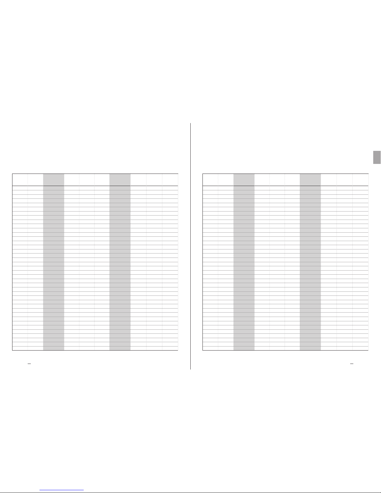
8483
Heat Exchange SolutionsThermoKey Technisches Handbuch TC Anweisungen und technische Daten
DE
MT TC A DF DE 04 2017MT TC A DF DE 04 2017
DFX DFB PASSO 10,0 mmDFX DFB PASSO 7,0 mm
1
1
1
2
2
2
3
3
3
4
4
4
1
1
1
2
2
2
3
3
3
4
4
4
1
1
1
2
2
2
3
3
3
4
4
4
5
5
5
500
500
500
500
500
500
500
500
500
500
500
500
560
560
560
560
560
560
560
560
560
560
560
560
560
630
630
630
630
630
630
630
630
630
630
630
630
630
630
DFX1507004
DFX1507006
DFX1507008
DFX2507004
DFX2507006
DFX2507008
DFX3507004
DFX3507006
DFX3507008
DFX4507004
DFX4507006
DFX4507008
DFX1567004
DFX1567006
DFX1567008
DFX2567004
DFX2567006
DFX2567008
DFX3567004
DFX3567006
DFX3567008
DFX4567004
DFX4567006
DFX4567008
DFX1637004
DFX1637006
DFX1637008
DFX2637004
DFX2637006
DFX2637008
DFX3637004
DFX3637006
DFX3637008
DFX4637004
DFX4637006
DFX4637008
/
/
/
39,84
59,76
79,68
79,68
119,52
159,36
119,52
179,28
239,04
159,36
239,04
318,72
59,76
89,64
119,53
119,52
179,28
239,06
179,28
268,92
358,59
239,04
358,56
478,12
71,72
107,57
143,43
143,44
215,14
286,86
215,16
322,71
430,29
286,88
430,28
573,72
/
/
/
7,2
10,7
14,3
14,4
21,4
28,6
21,6
32,1
42,9
28,8
42,8
57,2
10,9
16,3
21,7
21,8
32,6
43,4
32,7
48,9
65,1
43,6
65,2
86,8
12,9
19,3
25,8
25,8
38,6
51,6
38,7
57,9
77,4
51,6
77,2
103,2
/
/
/
102
115
127
186
210
234
268
304
341
351
399
448
144
164
192
248
289
331
352
412
470
455
537
609
165
187
219
277
323
372
390
460
526
502
596
679
/
/
/
38,97
58,45
77,94
77,94
116,90
155,88
116,91
175,35
233,82
155,88
233,80
311,76
58,45
87,68
116,91
116,90
175,36
233,82
175,35
263,04
350,73
233,80
350,72
467,64
70,14
105,22
140,29
140,28
210,44
280,58
210,42
315,66
420,87
280,56
420,88
561,16
350,70
526,10
701,45
102
115
127
186
210
234
268
304
341
351
399
448
144
164
192
248
289
331
352
412
470
455
537
609
165
187
219
277
323
372
390
460
526
502
596
679
620
746
842
DFB1507004
DFB1507006
DFB1507008
DFB2507004
DFB2507006
DFB2507008
DFB3507004
DFB3507006
DFB3507008
DFB4507004
DFB4507006
DFB4507008
DFB1567004
DFB1567006
DFB1567008
DFB2567004
DFB2567006
DFB2567008
DFB3567004
DFB3567006
DFB3567008
DFB4567004
DFB4567006
DFB4567008
DFB1637004
DFB1637006
DFB1637008
DFB2637004
DFB2637006
DFB2637008
DFB3637004
DFB3637006
DFB3637008
DFB4637004
DFB4637006
DFB4637008
DFB5637004
DFB5637006
DFB5637008
1
1
1
2
2
2
3
3
3
4
4
4
1
1
1
2
2
2
3
3
3
4
4
4
1
1
1
2
2
2
3
3
3
4
4
4
5
5
5
500
500
500
500
500
500
500
500
500
500
500
500
560
560
560
560
560
560
560
560
560
560
560
560
560
630
630
630
630
630
630
630
630
630
630
630
630
630
630
DFX1501004
DFX1501006
DFX1501008
DFX2501004
DFX2501006
DFX2501008
DFX3501004
DFX3501006
DFX3501008
DFX4501004
DFX4501006
DFX1001008
DFX1561004
DFX1561006
DFX1561008
DFX2561004
DFX2561006
DFX2561008
DFX3561004
DFX3561006
DFX3561008
DFX4561004
DFX4561006
DFX4561008
DFX1631004
DFX1631006
DFX1631008
DFX2631004
DFX2631006
DFX2631008
DFX3631004
DFX3631006
DFX3631008
DFX4631004
DFX4631006
DFX4631008
/
/
/
28,65
42,97
57,30
57,30
85,94
114,60
85,95
128,91
171,90
114,60
171,88
229,20
42,97
64,46
85,95
85,94
128,92
171,90
128,91
193,38
257,85
171,88
257,84
343,80
51,57
77,35
103,14
103,14
154,70
206,28
154,71
232,05
309,42
206,28
309,40
412,56
/
/
/
7,2
10,7
14,3
14,4
21,4
28,6
21,6
32,1
42,9
28,8
42,8
57,2
10,9
16,3
21,7
21,8
32,6
43,4
32,7
48,9
65,1
43,6
65,2
86,8
12,9
19,3
25,8
25,8
38,6
51,6
38,7
57,9
77,4
51,6
77,2
103,2
/
/
/
101
113
125
184
206
229
264
298
333
347
391
437
142
160
187
243
281
322
344
402
457
446
524
593
162
183
214
272
315
362
382
449
511
492
581
660
/
/
/
28,28
42,42
56,56
56,56
84,84
113,12
84,84
127,26
169,68
113,12
169,68
226,24
42,42
63,63
84,84
84,84
127,26
169,68
127,26
190,89
254,52
169,68
254,52
339,36
50,90
76,35
101,81
101,80
152,70
203,62
152,70
229,05
305,43
203,60
305,40
407,24
254,50
381,75
509,05
12,7
19,1
25,4
25,4
38,2
50,8
38,1
57,3
76,2
50,8
76,4
101,6
19,1
28,6
38,1
38,2
57,2
76,2
57,3
85,8
114,3
76,4
114,4
152,4
22,9
34,3
45,7
45,8
68,6
91,4
68,7
102,9
137,2
91,6
137,2
182,8
114,5
171,5
228,5
12,7
19,1
25,4
25,4
38,2
50,8
38,1
57,3
76,2
50,8
76,4
101,6
19,1
28,6
38,1
38,2
57,2
76,2
57,3
85,8
114,3
76,4
114,4
152,4
22,9
34,3
45,7
45,8
68,6
91,4
68,7
102,9
137,2
91,6
137,2
182,8
114,5
171,5
228,5
101
113
125
184
206
229
264
298
333
347
391
437
142
160
187
243
281
322
344
402
457
446
524
593
162
183
214
272
315
362
382
449
511
492
581
660
607
727
817
DFB1501004
DFB1501006
DFB1501008
DFB2501004
DFB2501006
DFB2501008
DFB3501004
DFB3501006
DFB3501008
DFB4501004
DFB4501006
DFB1001008
DFB1561004
DFB1561006
DFB1561008
DFB2561004
DFB2561006
DFB2561008
DFB3561004
DFB3561006
DFB3561008
DFB4561004
DFB4561006
DFB4561008
DFB1631004
DFB1631006
DFB1631008
DFB2631004
DFB2631006
DFB2631008
DFB3631004
DFB3631006
DFB3631008
DFB4631004
DFB4631006
DFB4631008
DFB5631004
DFB5631006
DFB5631008
Motoren
Anzahl
Dmr
[mm]
MODELL
Äußere
Oberäche
[m2]
Äußere
Oberäche
[m2]
Internes
Volumen
[dm3]
Internes
Volumen
[dm3]
Gewicht
netto
[kg]
Gewicht
netto
[kg]
MODELL
Motoren
Anzahl
Dmr
[mm]
MODELL
Äußere
Oberäche
[m2]
Äußere
Oberäche
[m2]
Internes
Volumen
[dm3]
Internes
Volumen
[dm3]
Gewicht
netto
[kg]
Gewicht
netto
[kg]
MODELL

ES
MT TC A DF ES 04 2017
Manual técnico – TC
Serie DFX, DFB, DFN, DFC
Aeroevaporadores y aerorrefrigeradores
industriales double flujo
LA VERSÍON ORIGINAL DE ESTAS INSTRUCCCIONES
SE REDACTÓ EN ITALIANO
MT TC A DF ES 04 2017
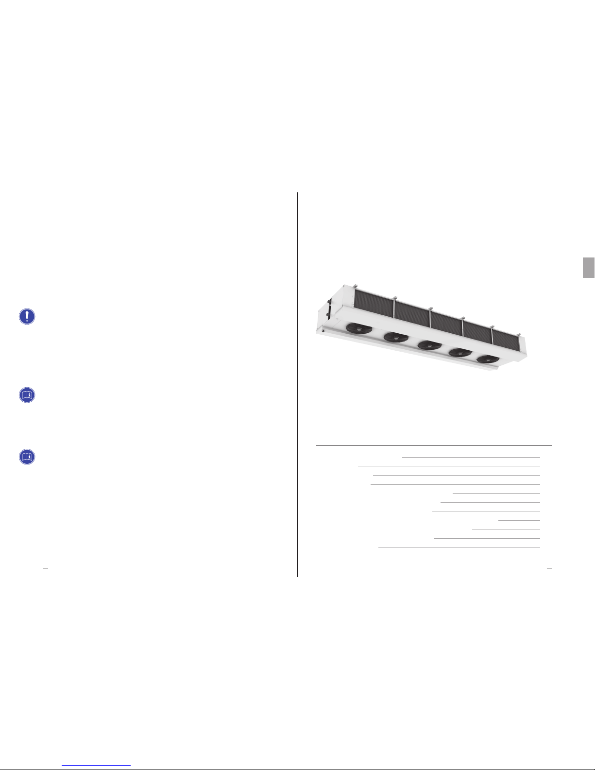
Heat Exchange SolutionsThermoKey Manual Técnico TC Instrucciones y datos técnicos
8786
ES
MT TC A DF ES 04 2017MT TC A DF ES 04 2017
LEER ATENTAMENTE Y COMPRENDER COMPLETAMENTE TODA LA
INFORMACIÓN PRESENTE EN ESTAS INSTRUCCIONES ANTES DEL
DISEÑO Y DE REALIZAR CUALQUIER OPERACIÓN DE DESPLAZAMIENTO,
DESEMBALAJE, MONTAJE, POSICIONAMIENTO Y PUESTA EN
FUNCIONAMIENTO DEL EQUIPO. EL FABRICANTE NO SE RESPONSABILIZA
POR DAÑOS A PERSONAS O COSAS DEBIDOS AL INCUMPLIMIENTO DE
LAS INDICACIONES DEL PRESENTE DOCUMENTO.
El original del presente manual está redactado en italiano y puede consultarse en el sitio de Internet:
www.thermokey.com.
La traducción en inglés es conforme al original y puede encontrarse en el sitio de Internet:
www.thermokey.com.
Las traducciones en otros idiomas pueden contener errores; en caso de dudas remitirse siempre a
la versión original en italiano o a su traducción en inglés.
El sistema de gestión de Calidad de ThermoKey está certificado como conforme a la norma ISO
9001, el sistema de gestión Ambiental conforme a la norma ISO 14001, y el sistema de gestión de
Seguridad como conforme a la norma OHSAS 18001.
Dual Flow
Industrial Unit Cooler
TC 1. REFERENCIAS NORMATIVAS
TC 2. PELIGROS
TC 3. ADVERTENCIAS
TC 4. USO PREVISTO
TC 5. INSPECCIÓN, DESPLAZAMIENTO Y TRANSPORTE
TC 6. MONTAJE Y PUESTA EN FUNCIONAMIENTO
TC 7. MANTENIMIENTO GENERAL Y CONTROL
TC 8. ESQUEMAS DE CONEXIÓN DE LAS RESISTENCIAS DE DESESCARCHE
TC 9. ESQUEMAS DE CONEXIÓN DE LOS MOTOVENTILADORES
TC 10. CARACTERÍSTICAS DE LAS DIMENSIONES
TC 11. DATOS TÉCNICOS
ÍNDICE
88
88
89
90
90
91
94
94
96
101
109

Heat Exchange SolutionsThermoKey Manual Técnico TC Instrucciones y datos técnicos
8988
ES
MT TC A DF ES 04 2017MT TC A DF ES 04 2017
Peligro de electrocución. El producto está equipado con electroventiladores y eventuales resistencias eléctricas de
desescarche con tensión nominal de funcionamiento de baja tensión trifásica y monofásica. Las líneas de alimentación
eléctrica deberán contar con los sistemas de protección contra descargas eléctricas y de protección del equipamiento
previstos por la normativa vig ente.
Peligro de quemaduras. En los productos equipados con resistencias eléctricas de desescarche, las temperaturas
superficiales de las carcasas, si se las deja encendidas sin control, pueden alcanzar los 350°C.
Peligro de corte. El intercambiador de calor, el cual forma parte del producto, está constituido por aletas metálicas con
bordes cortantes, no protegidas. La carrocería está constituida por componentes de chapa que, en algunos puntos, pueden
presentar bordes cortantes no protegidos.
Peligro por partes en movimiento. El producto está equipado con electroventiladores provistos de rejilla de protección
según lo previsto por la normativa vigente. En algunos productos podría ser posible acceder voluntariamente a las partes
en movimiento (aspas de los motoventiladores) desde zonas no protegidas. Antes de acceder, asegurarse de que las partes
en movimiento no constituyan peligro para los operadores.
Peligro de aplastamiento de los miembros o de la persona. Durante las fases de desplazamiento, transporte y instalación,
funcionamiento y mantenimiento, prestar la máxima atención al peso indicado de cada producto para evitar vuelcos o
caídas peligrosas para los operadores.
Peligro de caída de objetos. Los productos cuentan con puertas, bandejas o elementos de chapa de cubierta que, en fase
de instalación o mantenimiento, pueden desmontarse retirando los tornillos de fijación previstos; tomar las precauciones
adecuadas.
TC 2. Peligros
TC 1. Referencias normativas
El producto descrito en este manual es conforme a:
DIRECTIVA MÁQUINAS 2006/42/EC
DIRECTIVA BAJA TENSIÓN 2014/35/EU
DIRECTIVA COMPATIBILIDAD ELECTROMAGNÉTICA 2014/30/EU
DIRECTIVA PED 2014/68/EU
DIRECTIVA ErP 2009/125/EC
TC 3. Advertencias
TC 3.1
Contenido del Manual Técnico del producto:
INSTRUCCIONES GENERALES PARA EL USO SEGURO (IG)
INSTRUCCIONES PARA EL DESPLAZAMIENTO Y EL DESEMBALAJE (IM)
INSTRUCCIONES Y DATOS TÉCNICOS (TC)
INSTRUCCIONES ESPECÍFICAS DE USO Y MANTENIMIENTO (IS)
TC 3.2
Este manual es la sección TC denominada INSTRUCCIONES Y DATOS TÉCNICOS del Manual Técnico del producto.
Para cualquier información no contemplada en el presente manual, remitirse a las demás secciones (IG–IM–IS) y,
en caso de dudas, contactar con el Fabricante.
TC 3.3
Este manual forma parte de los equipos DFX DFB DFN Y DFC y, como tal, debe conservarse durante toda la vida útil
del producto.
TC 3.4
La eventual documentación técnica adicional con respecto a los productos no estándar se anexa al presente manual,
formando parte integrada codificada con código específico indicado en los documentos de envío.
TC 3.5
El producto descrito en este manual se considera una cuasi-máquina, por ende, no puede utilizarse tal como se lo
suministra, sino que es un componente para sistemas de acondicionamiento o refrigeración, y debe ser instalado y
puesto en funcionamiento por operadores cualificados (véase el capítulo correspondiente a la instalación y a la puesta
en funcionamiento).
TC 3.6
Cada producto cuenta con la Declaración de Incorporación CE.
TC 3.7
Otra documentación con respecto al producto, constituida por catálogos, guías y folletos técnicos, es suministrada
directamente por Thermokey y puede consultarse en el sitio de Internet www.thermokey.com.
CATÁLOGOS – http://www.thermokey.com/Cataloghi.aspx
MANUALES – http://www.thermokey.com/Manuali.aspx

Heat Exchange SolutionsThermoKey Manual Técnico TC Instrucciones y datos técnicos
9190
ES
MT TC A DF ES 04 2017MT TC A DF ES 04 2017
TC 4. Uso previsto
TC 4.1
El equipo debe utilizarse exclusivamente para la finalidad que se indica a continuación; de lo contrario, el uso debe
considerarse inadecuado y exonera al fabricante de cualquier responsabilidad consiguiente.
TC 4.2
Los aeroevaporadores o aerorrefrigeradores industriales de la serie DFX DFB DFN y DFC están diseñados para ser utilizados en
todos los sectores alimentarios, en las cámaras frigorícas medianas y grandes o almacenes refrigerados, para la conservación del
producto fresco y congelado, e incluso para la refrigeración y el acondicionamiento de salas de elaboración medianas y grandes.
Todas las unidades estándar están equipadas con grupo de ventilación de alta eciencia para una óptima distribución del aire.
TC 4.3
El modelo estándar está equipado con motoventiladores no adecuados para soportar cargas estáticas adicionales como
las generadas por las canalizaciones, túneles de congelación, etc.
TC 4.4
En caso de dudas sobre el uso previsto, contactar con el Fabricante.
TC 5. Inspección, desplazamiento y transporte
TC 5.1
Al recibir el equipo, asegurarse de la integridad del embalaje y del producto; reclamar de inmediato al transportista
por cualquier eventual daño que se haya verificado. El embalaje se ha fabricado en conformidad con el equipo, con los
medios de transporte adecuados y de desplazamiento.
TC 5.2
Durante el transporte y el desplazamiento del equipo en su embalaje, evitar esfuerzos no conformes e inadecuados
en el producto embalado; atenerse a todas las indicaciones ilustradas y mantener el equipo siempre en la posición
indicada en la figura (véase Fig.1).
TC 5.3
Durante el transporte y el desplazamiento del producto embalado, utilizar las protecciones específicas para evitar
herirse con las partes del embalaje como clavos, tablas o cartón, y las partes del equipo, como aletas o la carrocería
(véase EPI manual técnico sección I cap. I.G.6).
TC 5.4
Desembalar el equipo lo más cerca posible del lugar de instalación (véase incluso instalación y puesta en funcionamiento).
En general, el equipo no debe transportarse ni moverse sin el embalaje original.
TC 5.5
Durante el desplazamiento para la instalación del equipo desembalado, utilizar las protecciones adecuadas para evitar herirse
con las partes cortantes como las aletas o la carrocería (véase EPI manual técnico sección I cap. IG6).
TC 6.1
La instalación y la puesta en funcionamiento del equipo deben ser llevadas a cabo por personal experto y cualificado.
Para la fijación, seguir el esquema indicado en la figura (Fig.2).
TC 6.2
Para una circulación correcta del aire, verificar que en el ambiente de instalación se garanticen volúmenes libres
y pasos adecuados de aire, conformes a las características de caudal y flecha de aire del equipo. De lo contrario,
podrían no garantizarse las prestaciones declaradas y generarse defectos de funcionamiento. Atención a no obstruir la
aspiración ni el envío de los motoventiladores y del intercambiador (véase Fig.3).
TC 6.3
Verificar que las estructuras de soporte y las fijaciones sean conformes al peso y a la forma del equipo (véanse los
capítulos Características de las Dimensiones y Datos Técnicos).
TC 6.4
Fijar el equipo a todos los puntos previstos (véase el capítulo Características de las Dimensiones) con fijaciones
adecuadas y conformes al peso total (peso neto del equipo, peso del refrigerante, peso de la eventual acumulación de
hielo en el intercambiador, peso de la eventual acumulación en las bandejas de recogida de la condensación).
TC 6.5
El equipo no está diseñado para soportar cargas adicionales.
TC 6.6
En los modelos con desescarche eléctrico, verificar que se garantice o preparar el espacio adecuado para permitir la
sustitución de las resistencias introducidas en los intercambiadores.
fig.1 - Para un desplazamiento seguro, las horquillas
siempre deben sobresalir de la jaula de madera.
TC 6. Montaje y puesta en funcionamiento

Heat Exchange SolutionsThermoKey Manual Técnico TC Instrucciones y datos técnicos
9392
ES
MT TC A DF ES 04 2017MT TC A DF ES 04 2017
TC 6.7
En los ambientes con varias unidades instaladas no se deben realizar desescarches alternados para evitar la formación
anómala de escarcha en los intercambiadores.
TC 6.8
Vericar que la línea de alimentación eléctrica sea conforme a las características del equipo indicadas en los datos de placa.
TC 6.9
Antes de conectar el equipo, vericar que se hayan utilizado los dispositivos de seccionamiento e interrupción de la red
de alimentación, de protección contra las descargas eléctricas, de protección del equipamiento y todo lo previsto por la
normativa vigente. Los modelos estándar se suministran con cajas de derivación para la alimentación de los motoventiladores
y, en los modelos con desescarche eléctrico, con cajas de derivación para la alimentación de las resistencias.
TC 6.10
Si se utilizan dispositivos de regulación del número de revoluciones de los motoventiladores, verificar su compatibilidad;
los dispositivos no compatibles pueden generar ruidos y daños en los motoventiladores; el fabricante no garantiza las
prestaciones indicadas para equipos provistos de dispositivos de regulación.
TC 6.11
Verificar que la línea del refrigerante sea adecuada para las prestaciones del equipo. En fase de conexión del circuito
de refrigerante, no deformar los conductos ni modificar la posición del distribuidor o de los colectores en general.
TC 6.12
Verificar que los límites de funcionamiento (humedad, temperaturas y presiones) sean conformes a las características
de selección del producto.
TC 6.13
Para los modelos con desescarche eléctrico, en función del tipo de cámara, denir correctamente el tiempo y el número
de ciclos de desescarche. El desescarche debe controlarse mediante cronotermostato y las sondas de temperatura no deben
interrumpir el ciclo de desescarche antes de tiempo, sino solo una eventual sobretemperatura; estas deben estar ubicadas
en las zonas más frías del intercambiador (zonas con mayor formación de escarcha) y a distancia de las resistencias.
TC 6.14
Verificar que al finalizar cada ciclo de desescarche eléctrico o mediante gas o glicol caliente el paquete aleteado, la
bandeja interna y las descargas de condensación estén limpios. Corregir, eventualmente, los tiempos y el número de
ciclos de desescarche. Las acumulaciones de escarcha tienden a transformarse en acumulaciones de hielo perjudiciales
que pueden provocar el mal funcionamiento o la rotura del intercambiador.
TC 6.15
Montar en la línea de descarga de la condensación los sifones adecuados y verificar su eficacia con todas las temperaturas
de uso. En las cámaras de baja temperatura, es decir, para el funcionamiento por debajo del punto de congelamiento, la
humedad externa que entra en la línea de descarga sin sifones crea acumulaciones de hielo perjudiciales.
TC 6.16
La posibilidad de acceder al equipo instalado, para cualquier intervención, debe estar reservada al personal experto y
cualicado para conducir la instalación, en conformidad con las normas vigentes.
fig.2 – Secuencia de fijación:
a) retirar la tapa de la jaula de madera,
b) secuencia para una posible instalación facilitada solo para modelos estándar con hasta un máximo de dos
motoventiladores, retirar incluso los laterales y los cabezales de la jaula de madera,
c) levantar y posicionar,
d) fijar el equipo a todos los puntos previstos con fijaciones adecuadas y conformes al peso total (peso neto del equipo,
peso del refrigerante, peso de la eventual acumulación de hielo en el intercambiador, peso de la eventual acumulación en
las bandejas de recogida de la condensación),
e) retirar la jaula de madera y los suportes de transporte,
f) retirar el fondo de la jaula de madera y los suporte de transporte.
c) e d)
c) e d)
a) e b)
e) f)
a)

Heat Exchange SolutionsThermoKey Manual Técnico TC Instrucciones y datos técnicos
9594
ES
MT TC A DF ES 04 2017MT TC A DF ES 04 2017
TC 7. Mantenimiento genral y control
TC 7.1
Antes de realizar cualquier intervención de mantenimiento, asegurarse de que se haya cortado la alimentación
eléctrica del equipo: las partes eléctricas podrían estar conectadas a controles automáticos. Todas las operaciones
de mantenimiento deben ser llevadas a cabo por personal experto y cualificado.
TC 7.2
El equipo está constituido principalmente por: un intercambiador de calor con paquete aleteado, una carrocería portante de
chapa con paneles, tapas y bandejas de recogida de la condensación que pueden abrirse, por electroventiladores y, en los modelos
con desescarche eléctrico, se introducen en el intercambiador y se jan a las bandejas internas resistencias con carcasa de acero
inoxidable, con terminales vulcanizados y dispositivos de bloqueo que evitan el deslizamiento de las mismas (véase g.4).
TC 7.3
Verificar periódicamente las fijaciones del equipo, las conexiones eléctricas y las conexiones a la línea del refrigerante.
TC 7.4
Limpiar periódicamente la carrocería y el intercambiador utilizando detergentes adecuados o, eventualmente, agua
y jabón con pH neutro. No utilizar detergentes agresivos, solventes, soluciones ácidas o básicas y que contengan
principalmente cloro o amoniaco. Evitar el uso de abrasivos en general. Si se utilizan higienizantes, verificar su
compatibilidad con los materiales. En caso de dudas, contactar con el Fabricante.
TC 7.5
Controlar la eficacia del desescarche. Para los modelos con desescarche eléctrico, verificar periódicamente el
funcionamiento de todas las resistencias. El fabricante no se responsabiliza, de ninguna manera, por defectos y daños
determinados por mal funcionamientos no detectados (por ej.: acumulaciones perjudiciales de hielo).
fig.3 – Distancia mínima de las paredes
Nota: atención a no obstruir la aspiración ni el envío de aire de los motoventiladores y del intercambiador.
<< MIN. 1m >> << MIN. 1m >>
TC 7.6
Sustituir las resistencias eléctricas que no funcionan. Prestar especial atención en las fases de montaje para evitar
dañar los aislamientos vulcanizados; restablecer correctamente todas las conexiones (véanse los esquemas anexos) y
todos los sistemas de bloqueo para evitar la migración de las mismas durante el funcionamiento.
TC 7.7
Los períodos de control y mantenimiento dependen del tipo de cámara, por ende, deben ser definidos por personal
experto y cualificado.
TC 7.8
Para cualquier operación en el equipo, no descrita en este manual, contactar con el Fabricante.
fig.4 – Componenti
a) las tapas frontales se pueden desmontar para facilitar el acceso al compartimiento de colectores en las fases de
instalación y mantenimiento. El cierre se asegura con tornillos,
b) las tapas inferiores son desmontables para garantizar la accesibilidad completa al compartimiento de colectores,
c) las bandejas cuentan con bisagras para facilitar el acceso a la bandeja para la eventual sustitución de las resistencias
de desescarche o para las operaciones de limpieza; eventualmente, pueden desmontarse si es necesaria la sustitución,
d) los motoventiladores cuentan con rejilla de protección portante para permitir las eventuales operaciones de sustitución
completamente desde el exterior.
TAPAS
INFERIORES
DESMONTABLES
TAPAS
FRONTALES
PARA ABRIR
BANDEJAS
PARA ABRIR
Y DESMONTABLES
MOTOVENTILADORES

Heat Exchange SolutionsThermoKey Manual Técnico TC Instrucciones y datos técnicos
9796
ES
MT TC A DF ES 04 2017MT TC A DF ES 04 2017
TC 8. Escquemas de conexión y potencias
de las resistencias de desescarche
TC 8.1
El chasis de cada equipo cuenta con un polo de tierra (PE) con etiqueta de identificación.
Es obligatorio conectar el polo de tierra del equipo a la instalación o al conductor externo de puesta a tierra.
TC 8.2
Es obligatorio utilizar los sistemas de protección contra la descarga eléctrica y de protección del equipamiento en las
líneas de alimentación de las resistencias de desescarche.
TC 8.3
Verificar periódicamente el funcionamiento de todas las resistencias de desescarche para evitar que en los equipos se
formen acumulaciones de hielo perjudiciales debido a mal funcionamientos no detectados.
DFX DFB DFN DFC Ø 500 mm 04 RR
ALIMENTACIÓN ~3 400V 50-60HZ
CONEXIÓN EN ESTRELLA CON NEUTRO
Potencia batería
Potencia bandeja
Potencia total
3400
1700
5100
6800
3400
10200
10200
5100
15300
13600
6800
20400
150 45 04
150 70 04
150 10 04
250 45 04
250 70 04
250 10 04
350 45 04
350 70 04
350 10 04
450 45 04
450 70 04
450 10 04
MODELOS E
DFX DFB DFN DFC
(W)
(W)
(W)
HTH1
HTH2
HTH3
HTH4
HTL1 HTL3HTL2 HTL4
PE
HTH = Resistencia de alta potencia (*) HTL = Resistencia de baja potencia (*)
(*) La resistencia de alta potencia HTH tiene una potencia doble con respecto a la de baja potencia HTL
Potencia batería
Potencia bandeja
Potencia total
5950
1700
7650
11900
3400
15300
17850
5100
22950
23800
6800
30600
150 45 08
150 70 08
150 10 08
250 45 08
250 70 08
250 10 08
350 45 08
350 70 08
350 10 08
450 45 08
450 70 08
450 10 08
MODELOS E
DFX DFB DFN DFC
(W)
(W)
(W)
Potenza batteria
Potenza sgocciolatoio
Potenza totale
3400
1700
5100
6800
3400
10200
10200
5100
15300
13600
6800
20400
150 45 06
150 70 06
150 10 06
250 45 06
250 70 06
250 10 06
350 45 06
350 70 06
350 10 06
450 45 06
450 70 06
450 10 06
MODELOS E
DFX DFB DFN DFC
(W)
(W)
(W)
DFX DFB DFN DFC Ø 500 mm 06 RR
DFX DFB DFN DFC Ø 500 mm 08 RR
HTH = Resistencia de alta potencia (*) HTL = Resistencia de baja potencia (*)
(*) La resistencia de alta potencia HTH tiene una potencia doble con respecto a la de baja potencia HTL
HTH = Resistencia de alta potencia (*) HTL = Resistencia de baja potencia (*)
(*) La resistencia de alta potencia HTH tiene una potencia doble con respecto a la de baja potencia HTL
ALIMENTACIÓN ~3 400V 50-60HZ
CONEXIÓN EN ESTRELLA CON NEUTRO
ALIMENTACIÓN ~3 400V 50-60HZ
CONEXIÓN EN ESTRELLA CON NEUTRO
HTH1
HTL1
HTL3
HTL2
HTL4
HTH2
HTL5 HTL7HTL6 HTL8
HTH1
HTH3
HTL2
HTL1
HTH6
HTH5
HTL3 HTL5HTL4 HTL6
HTH4HTH2
PE
PE

Heat Exchange SolutionsThermoKey Manual Técnico TC Instrucciones y datos técnicos
9998
ES
MT TC A DF ES 04 2017MT TC A DF ES 04 2017
DFX DFB DFN DFC Ø 560 mm 04 RR
DFX DFB DFN DFC Ø 560 mm 06 RR
ALIMENTACIÓN ~3 400V 50-60HZ
CONEXIÓN EN ESTRELLA CON NEUTRO
ALIMENTACIÓN ~3 400V 50-60HZ
CONEXIÓN EN ESTRELLA CON NEUTRO
HTH1 HTH2
HTL1 HTL3
HTL2 HTL4
HTL5 HTL7HTL6 HTL8
HTH1 HTH4
HTH2 HTH5
HTH3 HTH6
HTL1 HTL2
HTL3 HTL5HTL4 HTL6
PE
PE
Potencia batería
Potenbandeja
Potencia total
3400
1700
5100
6800
3400
10200
10200
5100
15300
13600
6800
20400
156 45 04
156 70 04
156 10 04
256 45 04
256 70 04
256 10 04
356 45 04
356 70 04
356 10 04
456 45 04
456 70 04
456 10 04
MODELOS E
DFX DFB DFN DFC
(W)
(W)
(W)
HTH = Resistencia de alta potencia (*) HTL = Resistencia de baja potencia (*)
(*) La resistencia de alta potencia HTH tiene una potencia doble con respecto a la de baja potencia HTL
Potencia batería
Potencia bandeja
Potencia total
5950
1700
7650
11900
3400
15300
17850
5100
22950
23800
6800
30600
156 45 06
156 70 06
156 10 06
256 45 06
256 70 06
256 10 06
356 45 06
356 70 06
356 10 06
456 45 06
456 70 06
456 10 06
MODELOS E
DFX DFB DFN DFC
(W)
(W)
(W)
HTH = Resistencia de alta potencia (*) HTL = Resistencia de baja potencia (*)
(*) La resistencia de alta potencia HTH tiene una potencia doble con respecto a la de baja potencia HTL
DFX DFB DFN DFC Ø 630 mm 04 RR
ALIMENTACIÓN ~3 400V 50-60HZ
CONEXIÓN EN ESTRELLA CON NEUTRO
ALIMENTACIÓN ~3 400V 50-60HZ
CONEXIÓN EN ESTRELLA CON NEUTRO
Potencia batería
Potencia bandeja
Potencia total
8500
1700
10200
17000
3400
20400
25500
5100
30600
34000
6800
40800
156 45 08
156 70 08
156 10 08
256 45 08
256 70 08
256 10 08
356 45 08
356 70 08
356 10 08
456 45 08
456 70 08
456 10 08
MODELOS E
DFX DFB DFN DFC
(W)
(W)
(W)
HTH = Resistencia de alta potencia (*) HTL = Resistencia de baja potencia (*)
(*) La resistencia de alta potencia HTH tiene una potencia doble con respecto a la de baja potencia HTL
HTH = Resistencia de alta potencia (*) HTL = Resistencia de baja potencia (*)
(*) La resistencia de alta potencia HTH tiene una potencia doble con respecto a la de baja potencia HTL
DFX DFB DFN DFC Ø 560 mm 08 RR
HTH1 HTH5
HTL2 HTL4
HTH2 HTH6
HTH3
HTL3
HTH4
HTH7
HTL1
HTH8
HTL5 HTL7HTL6 HTL8
PE
HTH1
HTL2
HTL1
HTH2
HTL4
HTL3
HTL5 HTL7HTL6 HTL8
PE
Potencia Batería
Potencia bandeja
Potencia Total
3680
1840
5520
7360
3680
11040
11040
5520
16560
14720
7360
22080
18400
9200
27600
163 45 04
163 70 04
163 10 04
263 45 04
263 70 04
263 10 04
363 45 04
363 70 04
363 10 04
463 45 04
463 70 04
463 10 04
563 45 04
563 70 04
563 10 04
MODELLI
DFX DFB DFN DFC
(W)
(W)
(W)

Heat Exchange SolutionsThermoKey Manual Técnico TC Instrucciones y datos técnicos
101100
ES
MT TC A DF ES 04 2017MT TC A DF ES 04 2017
DFX DFB DFN DFC Ø 630 mm 06 RR
DFX DFB DFN DFC Ø 630 mm 08 RR
HTH = Resistencia de alta potencia (*) HTL = Resistencia de baja potencia (*)
(*) La resistencia de alta potencia HTH tiene una potencia doble con respecto a la de baja potencia HTL
HTH = Resistencia de alta potencia (*) HTL = Resistencia de baja potencia (*)
(*) La resistencia de alta potencia HTH tiene una potencia doble con respecto a la de baja potencia HTL
Potencia batería
Potencia bandeja
Potencia total
9200
1840
11040
18400
3680
22080
27600
5520
33120
36800
7360
44160
46000
9200
55200
163 45 08
163 70 08
163 10 08
263 45 08
263 70 08
263 10 08
363 45 08
363 70 08
363 10 08
463 45 08
463 70 08
463 10 08
563 45 08
563 70 08
563 10 08
MODELOS E
DFX DFB DFN DFC
(W)
(W)
(W)
Potencia batería
Potencia bandeja
Potencia total
6440
1840
8280
12880
3680
16560
19320
5520
24840
25760
7360
33120
32200
9200
41400
163 45 06
163 70 06
163 10 06
263 45 06
263 70 06
263 10 06
363 45 06
363 70 06
363 10 06
463 45 06
463 70 06
463 10 06
563 45 06
563 70 06
563 10 06
MODELOS E
DFX DFB DFN DFC
(W)
(W)
(W)
HTH1 HTH5
HTL2 HTL4
HTH2 HTH6
HTH3
HTL3
HTH4
HTH7
HTL1
HTH8
HTL5 HTL7HTL6 HTL8
PE
HTH1 HTH4
HTH2 HTH5
HTH3 HTH6
HTL1 HTL2
HTL3 HTL5HTL4 HTL6
PE
ALIMENTACIÓN ~3 400V 50-60HZ
CONEXIÓN EN ESTRELLA CON NEUTRO
ALIMENTACIÓN ~3 400V 50-60HZ
CONEXIÓN EN ESTRELLA CON NEUTRO
TC 9. Esquemas de conexión y consumo
de los motoventiladores
TC 9.1
El chasis de cada equipo cuenta con un polo de tierra (PE) con etiqueta de identificación. Es obligatorio conectar el
polo de tierra del equipo a la instalación o al conductor externo de puesta a tierra.
TC 9.2
En los equipos con motoventiladores cableados, es obligatorio conectar los conductores de protección de los
motoventiladores a la instalación o al conductor externo de puesta a tierra.
TC 9.3
Es obligatorio utilizar los sistemas de protección contra la descarga eléctrica y de protección del equipamiento en
las líneas de alimentación de los motoventiladores. Los motoventiladores cuentan con termocontactos normalmente
cerrados introducidos en los devanados del motor. Conectar los termocontactos para proteger el motor de las
sobretemperaturas. Atención: una sobretemperatura puede no depender directamente de una sobrecorriente.
Atención: el termocontacto se cierra al descender la temperatura, sin restablecerlo manualmente.
TC 9.4
Seguir rigurosamente los esquemas eléctricos indicados para evitar dañar los motores (a,b,c,d,e).
TC 9.5
Para equipos provistos de motoventiladores no estándar, remitirse a los esquemas y consumos indicados en las hojas
anexas y en los datos de placa.
TC 9.6
Antes de utilizar sistemas de regulación del número de revoluciones de los motoventiladores, verificar su
compatibilidad; los reguladores no compatibles pueden generar ruidos y daños en los motoventiladores; el fabricante
no asume responsabilidad alguna con respecto a las prestaciones de los equipos provistos de sistemas de regulación si
estos no se definen en la fase de oferta.

Heat Exchange SolutionsThermoKey Manual Técnico TC Instrucciones y datos técnicos
103102
ES
MT TC A DF ES 04 2017MT TC A DF ES 04 2017
a) Esquema de conexión de los motoventiladores estándar
b) Motor conectado en triángulo (alta velocidad) c) Motor conectado en estrella (baja velocidad)
d) Esquema borneras caja de derivación principal de 1 a 5 motoventiladores.
Conexión de alimentación en paralelo y serial termocontactos (pre-instalada).
Conexión individual disponible extrayendo los puentes.

547
250 250
577
1511
547
250 250
577
2511
547
250 250
577
3004
3511
FIJACIÓN 1004
FIJACIÓN 2004
FIJACIÓN 2002
FIJACIÓN 1002
Heat Exchange SolutionsThermoKey Manual Técnico TC Instrucciones y datos técnicos
105104
ES
MT TC A DF ES 04 2017MT TC A DF ES 04 2017
1
2
3
4
1
2
3
4
1
2
3
4
5
500
500
500
500
560
560
560
560
630
630
630
630
630
N° MOTORES DIÁMETRO
NOMINAL
0,77
1,54
2,31
3,08
1,05
2,10
3,15
4,20
1,25
2,50
3,75
5,00
6,25
1,7
3,4
5,1
6,8
2,2
4,4
6,6
8,8
2,48
4,96
7,44
9,92
12,4
ALTA VELOCIDAD
KW A
0,49
0,98
1,47
1,96
0,58
1,16
1,74
2,32
0,84
1,68
2,52
3,36
4,20
0,84
1,68
2,52
3,36
1,1
2,2
3,3
4,4
1,42
2,84
4,26
5,68
7,10
KW A
BAJA VELOCIDAD
e) Consumos nominales de los motoventiladores estándar
TC 10. Características de las dimensiones
DFX DFB DFN DFC Ø 500 mm
1X500
2X500
3X500
4X500
547
4004250 250
577
4511
FIJACIÓN 2002 FIJACIÓN 2002

776
748
300 300
1611
776
748
2004300 300
2611
776
748
3004300 300
3612
776
748
4004300 300
4612
804
767
2404300 300
3013
FIJACIÓN 1004
FIJACIÓN 1002FIJACIÓN 1002
FIJACIÓN 1002 FIJACIÓN 1002FIJACIÓN 1000
FIJACIÓN 1000FIJACIÓN 1002 FIJACIÓN 1002FIJACIÓN 1000
FIJACIÓN 1204
FIJACIÓN 1202 FIJACIÓN 1202
FIJACIÓN 1202
FIJACIÓN 1202 FIJACIÓN 1202
FIJACIÓN 1202FIJACIÓN 1202
FIJACIÓN 1202FIJACIÓN 1200
FIJACIÓN 1200
FIJACIÓN 1200 FIJACIÓN 1200 FIJACIÓN 1200
FIJACIÓN 1200
Heat Exchange SolutionsThermoKey Technical Manual TC Instruction and technical data
107106
EN
MT TC A DF EN 04 2017MT TC A DF EN 04 2017
DFX DFB DFN DFC Ø 560 mm
1X560
2X560
3X560
4X560
DFX DFB DFN DFC Ø 630 mm
804
767
300 300
1812
1X630 2X630
804
767
3604300 300
4212
3X630
804
767
4804300 300
5412
4X630
804
767
6004 300 300
6613
5X630

1810
449
1656
50
661
1960
1896 FIXING
50
863
470
1808
1960
50
886
470
1808
FIJACIÓN 1746
FIJACIÓN 1896
FIJACIÓN 1896
Heat Exchange SolutionsThermoKey Technical Manual TC Instruction and technical data
109108
EN
MT TC A DF EN 04 2017MT TC A DF EN 04 2017
DFX DFB DFN DFC
Ø 500 mm
Ø 560 mm
Ø 630 mm
TC 11. Datos técnicos
1
1
1
2
2
2
3
3
3
4
4
4
1
1
1
2
2
2
3
3
3
4
4
4
1
1
1
2
2
2
3
3
3
4
4
4
5
5
5
500
500
500
500
500
500
500
500
500
500
500
500
560
560
560
560
560
560
560
560
560
560
560
560
560
630
630
630
630
630
630
630
630
630
630
630
630
630
630
60,57
90,85
121,40
121,14
181,70
242,80
181,71
272,55
364,20
242,28
363,40
485,60
90,85
136,28
181,71
181,70
272,56
363,42
272,55
408,84
545,13
363,40
545,12
726,84
109,02
163,54
218,05
218,04
327,08
436,10
327,06
490,62
654,15
436,08
654,16
872,20
/
/
/
7,2
10,7
14,3
14,4
21,4
28,6
21,6
32,1
42,9
28,8
42,8
57,2
10,9
16,3
21,7
21,8
32,6
43,4
32,7
48,9
65,1
43,6
65,2
86,8
12,9
19,3
25,8
25,8
38,6
51,6
38,7
57,9
77,4
51,6
77,2
103,2
/
/
/
58,76
88,15
117,53
117,52
176,30
235,06
176,28
264,45
352,59
235,04
352,60
470,12
88,15
132,22
176,29
176,30
264,44
352,58
264,45
396,66
528,87
352,60
528,88
705,16
105,77
158,66
211,55
211,54
317,32
423,10
317,31
475,98
634,65
423,08
634,64
846,20
528,85
793,30
1057,75
12,7
19,1
25,4
25,4
38,2
50,8
38,1
57,3
76,2
50,8
76,4
101,6
19,1
28,6
38,1
38,2
57,2
76,2
57,3
85,8
114,3
76,4
114,3
76,4
114,4
152,4
22,9
34,3
45,7
45,8
68,6
91,4
68,7
102,9
137,2
182,8
114,5
171,5
228,5
104
118
131
190
216
241
274
312
352
358
409
462
148
168
198
257
297
348
361
425
488
467
553
632
169
192
226
287
333
392
401
474
546
516
615
705
638
770
875
104
118
131
190
216
241
274
312
352
358
409
462
148
168
198
257
297
348
361
425
488
467
553
632
169
192
226
287
333
392
401
474
546
516
615
705
/
/
/
DFX1504504
DFX1504506
DFX1504508
DFX2504504
DFX2504506
DFX2504508
DFX3504504
DFX3504506
DFX3504508
DFX4504504
DFX4504506
DFX4504508
DFX1564504
DFX1564506
DFX1564508
DFX2564504
DFX2564506
DFX2564508
DFX3564504
DFX3564506
DFX3564508
DFX4564504
DFX4564506
DFX4564508
DFX1634504
DFX1634506
DFX1634508
DFX2634504
DFX2634506
DFX2634508
DFX3634504
DFX3634506
DFX3634508
DFX4634504
DFX4634506
DFX4634508
/
/
/
DFB1504504
DFB1504506
DFB1504508
DFB2504504
DFB2504506
DFB2504508
DFB3504504
DFB3504506
DFB3504508
DFB4504504
DFB4504506
DFB4504508
DFB1564504
DFB1564506
DFB1564508
DFB2564504
DFB2564506
DFB2564508
DFB3564504
DFB3564506
DFB3564508
DFB4564504
DFB4564506
DFB4564508
DFB1634504
DFB1634506
DFB1634508
DFB2634504
DFB2634506
DFB2634508
DFB3634504
DFB3634506
DFB3634508
DFB4634504
DFB4634506
DFB4634508
DFB5634504
DFB5634506
DFB5634508
Mot.n°Diá
[mm]
MODELO
Supercie
externa
[m2]
Supercie
externa
[m2]
Volumen
Interno
[dm3]
Volumen
Interno
[dm3]
Peso
neto
[kg]
Peso
neto
[kg]
MODELO
DFX DFB PASO 4,5 mm
32
70
18x30
32
70
18x30
32
70
18X30

Heat Exchange SolutionsThermoKey Technical Manual TC Instruction and technical data
111110
EN
MT TC A DF EN 04 2017MT TC A DF EN 04 2017
DFX DFB PASO 10,0 mmDFX DFB PASO 7,0 mm
1
1
1
2
2
2
3
3
3
4
4
4
1
1
1
2
2
2
3
3
3
4
4
4
1
1
1
2
2
2
3
3
3
4
4
4
5
5
5
500
500
500
500
500
500
500
500
500
500
500
500
560
560
560
560
560
560
560
560
560
560
560
560
560
630
630
630
630
630
630
630
630
630
630
630
630
630
630
DFX1507004
DFX1507006
DFX1507008
DFX2507004
DFX2507006
DFX2507008
DFX3507004
DFX3507006
DFX3507008
DFX4507004
DFX4507006
DFX4507008
DFX1567004
DFX1567006
DFX1567008
DFX2567004
DFX2567006
DFX2567008
DFX3567004
DFX3567006
DFX3567008
DFX4567004
DFX4567006
DFX4567008
DFX1637004
DFX1637006
DFX1637008
DFX2637004
DFX2637006
DFX2637008
DFX3637004
DFX3637006
DFX3637008
DFX4637004
DFX4637006
DFX4637008
/
/
/
39,84
59,76
79,68
79,68
119,52
159,36
119,52
179,28
239,04
159,36
239,04
318,72
59,76
89,64
119,53
119,52
179,28
239,06
179,28
268,92
358,59
239,04
358,56
478,12
71,72
107,57
143,43
143,44
215,14
286,86
215,16
322,71
430,29
286,88
430,28
573,72
/
/
/
7,2
10,7
14,3
14,4
21,4
28,6
21,6
32,1
42,9
28,8
42,8
57,2
10,9
16,3
21,7
21,8
32,6
43,4
32,7
48,9
65,1
43,6
65,2
86,8
12,9
19,3
25,8
25,8
38,6
51,6
38,7
57,9
77,4
51,6
77,2
103,2
/
/
/
102
115
127
186
210
234
268
304
341
351
399
448
144
164
192
248
289
331
352
412
470
455
537
609
165
187
219
277
323
372
390
460
526
502
596
679
/
/
/
38,97
58,45
77,94
77,94
116,90
155,88
116,91
175,35
233,82
155,88
233,80
311,76
58,45
87,68
116,91
116,90
175,36
233,82
175,35
263,04
350,73
233,80
350,72
467,64
70,14
105,22
140,29
140,28
210,44
280,58
210,42
315,66
420,87
280,56
420,88
561,16
350,70
526,10
701,45
102
115
127
186
210
234
268
304
341
351
399
448
144
164
192
248
289
331
352
412
470
455
537
609
165
187
219
277
323
372
390
460
526
502
596
679
620
746
842
DFB1507004
DFB1507006
DFB1507008
DFB2507004
DFB2507006
DFB2507008
DFB3507004
DFB3507006
DFB3507008
DFB4507004
DFB4507006
DFB4507008
DFB1567004
DFB1567006
DFB1567008
DFB2567004
DFB2567006
DFB2567008
DFB3567004
DFB3567006
DFB3567008
DFB4567004
DFB4567006
DFB4567008
DFB1637004
DFB1637006
DFB1637008
DFB2637004
DFB2637006
DFB2637008
DFB3637004
DFB3637006
DFB3637008
DFB4637004
DFB4637006
DFB4637008
DFB5637004
DFB5637006
DFB5637008
Mot.n°Diá
[mm]
MODELO
Supercie
externa
[m2]
Supercie
externa
[m2]
Volumen
Interno
[dm3]
Volumen
Interno
[dm3]
Peso
neto
[kg]
Peso
netto
[kg]
MODELO
1
1
1
2
2
2
3
3
3
4
4
4
1
1
1
2
2
2
3
3
3
4
4
4
1
1
1
2
2
2
3
3
3
4
4
4
5
5
5
500
500
500
500
500
500
500
500
500
500
500
500
560
560
560
560
560
560
560
560
560
560
560
560
560
630
630
630
630
630
630
630
630
630
630
630
630
630
630
DFX1501004
DFX1501006
DFX1501008
DFX2501004
DFX2501006
DFX2501008
DFX3501004
DFX3501006
DFX3501008
DFX4501004
DFX4501006
DFX1001008
DFX1561004
DFX1561006
DFX1561008
DFX2561004
DFX2561006
DFX2561008
DFX3561004
DFX3561006
DFX3561008
DFX4561004
DFX4561006
DFX4561008
DFX1631004
DFX1631006
DFX1631008
DFX2631004
DFX2631006
DFX2631008
DFX3631004
DFX3631006
DFX3631008
DFX4631004
DFX4631006
DFX4631008
/
/
/
28,65
42,97
57,30
57,30
85,94
114,60
85,95
128,91
171,90
114,60
171,88
229,20
42,97
64,46
85,95
85,94
128,92
171,90
128,91
193,38
257,85
171,88
257,84
343,80
51,57
77,35
103,14
103,14
154,70
206,28
154,71
232,05
309,42
206,28
309,40
412,56
/
/
/
7,2
10,7
14,3
14,4
21,4
28,6
21,6
32,1
42,9
28,8
42,8
57,2
10,9
16,3
21,7
21,8
32,6
43,4
32,7
48,9
65,1
43,6
65,2
86,8
12,9
19,3
25,8
25,8
38,6
51,6
38,7
57,9
77,4
51,6
77,2
103,2
/
/
/
101
113
125
184
206
229
264
298
333
347
391
437
142
160
187
243
281
322
344
402
457
446
524
593
162
183
214
272
315
362
382
449
511
492
581
660
/
/
/
28,28
42,42
56,56
56,56
84,84
113,12
84,84
127,26
169,68
113,12
169,68
226,24
42,42
63,63
84,84
84,84
127,26
169,68
127,26
190,89
254,52
169,68
254,52
339,36
50,90
76,35
101,81
101,80
152,70
203,62
152,70
229,05
305,43
203,60
305,40
407,24
254,50
381,75
509,05
12,7
19,1
25,4
25,4
38,2
50,8
38,1
57,3
76,2
50,8
76,4
101,6
19,1
28,6
38,1
38,2
57,2
76,2
57,3
85,8
114,3
76,4
114,4
152,4
22,9
34,3
45,7
45,8
68,6
91,4
68,7
102,9
137,2
91,6
137,2
182,8
114,5
171,5
228,5
12,7
19,1
25,4
25,4
38,2
50,8
38,1
57,3
76,2
50,8
76,4
101,6
19,1
28,6
38,1
38,2
57,2
76,2
57,3
85,8
114,3
76,4
114,4
152,4
22,9
34,3
45,7
45,8
68,6
91,4
68,7
102,9
137,2
91,6
137,2
182,8
114,5
171,5
228,5
101
113
125
184
206
229
264
298
333
347
391
437
142
160
187
243
281
322
344
402
457
446
524
593
162
183
214
272
315
362
382
449
511
492
581
660
607
727
817
DFB1501004
DFB1501006
DFB1501008
DFB2501004
DFB2501006
DFB2501008
DFB3501004
DFB3501006
DFB3501008
DFB4501004
DFB4501006
DFB1001008
DFB1561004
DFB1561006
DFB1561008
DFB2561004
DFB2561006
DFB2561008
DFB3561004
DFB3561006
DFB3561008
DFB4561004
DFB4561006
DFB4561008
DFB1631004
DFB1631006
DFB1631008
DFB2631004
DFB2631006
DFB2631008
DFB3631004
DFB3631006
DFB3631008
DFB4631004
DFB4631006
DFB4631008
DFB5631004
DFB5631006
DFB5631008
Mot.n°Diá
[mm]
MODELO
Supercie
externa
[m2]
Supercie
externa
[m2]
Volumen
Interno
[dm3]
Volumen
Interno
[dm3]
Peso
neto
[kg]
Peso
neto
[kg]
MODELO

FR
MT TC A DF FR 04 2017
Manuel Technique – TC
Série DFX, DFB, DFN, DFC
Évaporateurs et frigorifères industriels
double flux
LA VERSION ORIGINALE DES PRESENTES
INSTRUCTIONS EST REDIGEE EN ITALIEN
MT TC A DF FR 04 2017

Heat Exchange SolutionsThermoKey Manuel Technique TC Instruction et donnés technique
114113
FR
MT TC A DF FR 04 2017MT TC A DF FR 04 2017
VEUILLEZ LIRE AVEC ATTENTION ET COMPRENDRE DANS LEUR
TOTALITÉ TOUTES LES INFORMATIONS CONTENUES DANS CES
INSTRUCTIONS AVANT LA CONCEPTION ET, DE TOUTE MANIÈRE,
AVANT D’EFFECTUER N’IMPORTE QUELLE OPÉRATION DE
MANUTENTION, DÉSEMBALLAGE, MONTAGE, PLACEMENT ET
MISE EN SERVICE DE L’APPAREIL. LE FABRICANT REJETTE TOUTES
RESPONSABILITÉS DE DOMMAGES AUX CHOSES OU PERSONNES
DÉCOULANT DU NON-RESPECT DES INDICATIONS CONTENUES DANS
LE DOCUMENT ICI PRÉSENT.
L’original du manuel ici présent est en italien, il est disponible sur le site internet:
www.thermokey.com.
La traduction en anglais est conforme à l’original et est disponible sur le site internet:
www.thermokey.com.
Les traductions dans d’autres langues peuvent contenir des erreurs ; en cas de doute,
faites toujours référence à la version originale en italien ou à sa traduction en anglais.
Le système de gestion de la Qualité ThermoKey est certifié en conformité à la norme ISO 9001.
Le système de gestion de l’Environnement de ThermoKey est certifié en conformité à la norme
ISO 14001 et le système de Securité de ThermoKey est certifié en conformité à la norme OHSAS
18001.
Évaporateurs
et Frigorifères Industriels
Double Flux
TC 1. RÉFÉRENCES NORMATIVES
TC 2. DANGERS
TC 3. AVERTISSEMENTS
TC 4. DESTINATION D’USAGE
TC 5. INSPECTION, MANUTENTION ET TRANSPORT
TC 6. INSTALLATION ET MISE EN SERVICE
TC 7. ENTRETIEN GÉNÉRAL ET CONTRÔLE
TC 8. SCHÉMAS DE RACCORDEMENT DES RÉSISTANCES DE DÉGIVRAGE
TC 9. SCHÉMAS DE RACCORDEMENT DES MOTO-VENTILATEURS
TC 10. CARACTÉRISTIQUES DIMENSIONNELLES
TC 11. DONNÉES TECHNIQUES
INDEX
115
115
116
117
117
118
121
123
128
132
136

Heat Exchange SolutionsThermoKey Manuel Technique TC Instruction et donnés technique
116115
FR
MT TC A DF FR 04 2017MT TC A DF FR 04 2017
Danger d’électrocution. Le produit est installé avec des électro-ventilateurs et des éventuelles résistances électriques
de dégivrage ayant une tension nominale de fonctionnement en baisse tension triphasée et monophasée. Les lignes
d’alimentation électrique devront utiliser des systèmes de protection contre les décharges électriques, et de protection de
l’équipement, prévus par les normes en vigueur.
Danger de brûlures. Si à l’intérieur des produits installés avec des résistances électriques de dégivrage, celles-ci restent
allumées sans être contrôlées, les températures superficielles des couvertures peuvent atteindre 350 °C.
Danger de coupe. L’échangeur de chaleur, est une partie intégrante du produit, et est composé d’ailettes métalliques, non
protégées, ayant des bords coupants. La carrosserie est composée de composants en laminages qui peuvent présenter sur
certaines zones des bords coupants non protégés.
Danger de pièces en mouvement. Le produit est installé avec des électro-ventilateurs munis de grillage de protection
selon ce qui est prévu par la norme en vigueur. Pour certains produits il pourrait être possible d’accéder volontairement
aux pièces en mouvement (pales des moto-ventilateurs) à partir de zones non protégées. Avant n’importe quel accès,
assurez-vous que les pièces en mouvement ne représentent pas de dangers pour les opérateurs.
Danger d’écrasement des membres inférieurs et supérieurs ou de la personne. Pendant les phases de déplacement,
transport et installation, fonctionnement et entretien, veuillez faire extrêmement attention au poids indiqué par chaque
produit pour éviter des basculements ou des chutes dangereuses en direction des opérateurs.
Danger de chute d’objets. Les produits sont munis de portes, de cuvettes ou de tôles intercalaires qui au moment de
l’installation ou de l’entretien peuvent être démontées en enlevant les vis de fixation prévues, prenez donc les précautions
opportunes.
TC 2. Dangers
TC 1. Références normatives
Le produit décrit dans ce manuel s’avère conforme à la:
DIRECTIVE MACHINES 2006/42/EC
DIRECTIVE BASSE TENSION 2014/35/EU
DIRECTIVE COMPATIBILITÉ ÉLECTRO MAGNÉTIQUE 2014/30/EU
DIRECTIVE ÉQUIPEMENTS SOUS PRESSION (PED) 2014/68/EU
DIRECTIVE PRODUITS LIÉS À LA CONSOMMATION D’ÉNERGIE (ERP) 2009/125/EC
TC 3. Avertissements
TC 3.1
Contenu du Manuel Technique du produit:
INSTRUCTIONS GÉNÉRALES POUR UNE UTILISATION EN TOUTE SÉCURITÉ (I.G.)
INSTRUCTIONS POUR LE LA MANUTENTION ET LE DÉSEMBALLAGE (I.D.)
INSTRUCTIONS ET DONNÉES TECHNIQUES (TC)
INSTRUCTIONS SPÉCIFIQUES D’UTILISATION ET ENTRETIEN (I.S.)
TC 3.2
Ce manuel est la section TC nommée INSTRUCTIONS ET DONNÉES TECHNIQUES du Manuel Technique du
produit. Pour toute information non envisagée dans ce manuel, veuillez faire référence aux autres sections (IG–ID–
IS), et en cas de doutes, contactez le Fabricant.
TC 3.3
Ce manuel est partie intégrante des modèles DFX DFB DFN et DFC, en tant que tel il doit être conservé pour toute la
durée de vie du produit.
TC 3.4
La documentation technique supplémentaire éventuelle relative aux produits non standards est annexée au manuel
ici présent, elle est intégrante et elle est codifiée avec un code spécifique indiqué sur les documents de livraison.
TC 3.5
Le produit décrit dans ce manuel est considéré comme étant une quasi-machine, il n’est donc pas utilisable tel qu’il est
fourni, mais c’est un élément qui sert à des installations de climatisation ou de réfrigération et il doit être installé et
mis en marche uniquement par des opérateurs qualifiés (voir chapitre concernant l’installation et la mise en marche).
TC 3.6
Chaque produit est accompagné d’une Déclaration d’Incorporation CE.
TC 3.7
Les catalogues, les guides et les bulletins techniques constituent une documentation ultérieure concernant le
produit. Elle est fournie directement par Thermokey et est disponible sur le site internet www.thermokey.com.
CATALOGUES – http://www.thermokey.com/Cataloghi.aspx
MANUELS – http://www.thermokey.com/Manuali.aspx

Heat Exchange SolutionsThermoKey Manuel Technique TC Instruction et donnés technique
118117
FR
MT TC A DF FR 04 2017MT TC A DF FR 04 2017
TC 4. Intended use
TC 4.1
Le modèle doit être utilisé exclusivement pour le but indiqué ici de suite. Autrement, son utilisation sera considérée
impropre et elle dispensera le fabricant de toute responsabilité conséquente.
TC 4.2
Les évaporateurs ventilés ou frigorifères industriels de la série DFX DFB DFN et DFC sont conçus pour être
utilisés dans tous les secteurs de l’alimentation, dans les chambres frigorifiques de moyenne et grande dimension
des entrepôts réfrigérés, pour la conservation de produits frais et surgelés et aussi pour la climatisation et le
rafraichissement des grandes et moyennes salles de travail. Toutes les unités standards sont équipées avec une unité
de ventilation à haute efficacité pour une distribution de l’air optimale.
TC 4.3
Le modèle standard est équipé avec des moto-ventilateurs non appropriés à supporter des pressions statiques
additionnelles comme celles qui dérivent des canalisations, des tunnels de refroidissement, etc.
TC 4.4
En cas de doute sur la destination d’usage, contactez le Fabricant.
TC 5. Inspection, manutention et transport
TC 5.1
À la réception du modèle, contrôlez l’état d’intégrité de l’emballage et du produit ; notifiez immédiatement au
transporteur n’importe quel dommage qui s’est éventuellement produit. L’emballage est fabriqué conformément au
modèle, aux moyens de transport et au déplacement appropriés.
TC 5.2
Pendant le transport et le déplacement du modèle dans son emballage, évitez des sollicitations non conformes et
impropres sur le produit emballé. Respectez toutes les indications illustrées et maintenez toujours le modèle dans la
position indiquée sur l’image (voir Img.1).
TC 5.3
Pendant le transport et le déplacement du produit emballé, utilisez des protections appropriées afin d’éviter de vous
blesser avec certaines parties de l’emballage comme des clous, des planches ou du carton et certaines parties du modèle
comme les ailettes ou la carrosserie (voir EPI manuel technique section I chap. I.G.6).
TC 5.4
Désemballez le modèle le plus près possible du lieu d’installation (voir aussi installation et mise en marche).
Généralement le modèle ne doit pas être transporté ou déplacé dépourvu de l’emballage original.
TC 5.5
Pendant l’installation du modèle désemballé, utilisez des protections appropriées an d’éviter de vous blesser avec les parties
coupantes comme les ailettes ou la carrosserie (voir EPI manuel technique section I chap. IG6).
TC 6.1
L’installation et la mise en marche du modèle doivent être réalisées par du personnel qualifié et expérimenté. Pour ce
qui concerne le fixage, suivez le schéma indiqué dans l’image (Img.2).
TC 6.2
Pour une circulation de l’air correcte, vérifiez que dans les espaces d’installation sont garantis des volumes libres et des
passages d’air appropriés et conformes aux caractéristiques de portée et de déflexion d’air du modèle. En cas contraire,
les performances déclarées pourraient ne pas être garanties et des défauts de fonctionnement pourraient se produire.
Faites attention à ne pas obstruer ni l’aspiration ni l’extraction des moto-ventilateurs et de l’échangeur (voir Img.3).
TC 6.3
Vérifiez que les structures de support et les ancrages sont conformes au poids et à la forme du modèle (voir chapitre
Caractéristiques Dimensionnelles et Données Techniques).
TC 6.4
Fixez le modèle à tous les points prévus (voir Chapitre Caractéristiques Dimensionnelles) avec les ancrages appropriés
et conformes au poids total (poids net du modèle, poids du réfrigèrent, poids de l’accumulation éventuelle de glace sur
l’échangeur, poids de l’accumulation éventuelle dans les cuvettes de récolte de la condensation).
TC 6.5
Le modèle n’est pas conçu pour supporter des charges supplémentaires.
TC 6.6
Dans les modèles avec dégivrage électrique, vérifiez qu’un espace approprié, permettant le remplacement des
résistances enfilées sur les échangeurs, est garanti. S’il ne l’est pas, prédisposez-le.
fig.1 - Pour un déplacement en toute sécurité les
fourches doivent toujours dépasser de la cage en
bois.
TC 6. Installation et mise en marche

Heat Exchange SolutionsThermoKey Manuel Technique TC Instruction et donnés technique
120119
FR
MT TC A DF FR 04 2017MT TC A DF FR 04 2017
TC 6.7
Dans les espaces avec plusieurs unités installées, vous ne devez pas effectuer de dégivrages alternés afin d’éviter la
formation anormale de givrage sur les échangeurs.
TC 6.8
Vérifiez que la ligne d’alimentation électrique est conforme aux caractéristiques, du modèle, indiquées sur les données
de la plaque.
TC 6.9
Avant de raccorder le modèle, vérifiez que les dispositifs de sectionnement et d’interruption du réseau d’alimentation,
que les protections contre les décharges électriques, que la protection de l’équipement et tout ce qui est prévu par les
normes en vigueur a été utilisé. Les modèles standards sont fournis avec des boîtes de jonction pour l’alimentation
des moto-ventilateurs. Dans les modèles avec dégivrage électrique, ils sont fournis avec des boîtes de jonction pour
l’alimentation des résistances.
TC 6.10
Si des dispositifs de régulation du nombre de tours des moto-ventilateurs sont utilisés, veuillez en vérifier la
compatibilité, car des dispositifs non compatibles peuvent produire des bruits et des dommages aux moto-ventilateurs.
Le fabricant ne garantit pas les performances indiquées pour les modèles équipés avec des dispositifs de régulation.
TC 6.11
Vérifiez que la ligne d’alimentation du réfrigérant est conforme aux performances du modèle. Au moment du
raccordement du circuit réfrigérant, ne pas déformer les capillaires et ne pas modifier la position du distributeur et
des collecteurs en général.
TC 6.12
Vérifiez que les limites de fonctionnement (humidité, température et pressions) sont conformes aux caractéristiques
de sélection du produit.
TC 6.13
Pour les modèles ayant dégivrage électrique, en fonction du type de la chambre frigorique, spéciez correctement le
temps et le nombre de cycles de dégivrage. Le dégivrage doit être chrono-thermorégulé, et les capteurs de température ne
doivent pas interrompre le cycle de dégivrage prématurément, mais seulement une surchaue éventuelle. Ils doivent être
placés dans les zones les plus froides de l’échangeur (zone avec une formation majeure de givre) et loin des résistances.
TC 6.14
Vérifiez que les ailettes, les égouttoirs, les écoulements de la condensation restent propres lors de la conclusion de
chaque cycle de dégivrage, qu’il soit électrique, à gaz chaud ou à glycols chauds. Corrigez éventuellement les temps et
le nombre de cycles de dégivrage. Des accumulations de givre ont tendance à se transformer en accumulations de glace
nocives qui peuvent provoquer le dysfonctionnement ou la rupture de l’échangeur.
TC 6.15
Installez sur la ligne de décharge de la condensation des siphons appropriés et vérifiez-en l’eff icacité avec toutes les
températures d’utilisation. Dans les chambres frigorifiques à températures basses, c’est-à-dire pour des fonctionnements
en dessous du point de congélation, l’humidité extérieure qui rentre dans la ligne de décharge dépourvue de siphons
réalise des accumulations de glace nocives.
Img.2 – Séquence de fixage:
a) retirez le couvercle de la cage de bois,
b) séquence réservée uniquement à une possible installation simplifiée et uniquement pour des modèles standards jusqu’à
un maximum de deux moto-ventilateurs, retirez donc également les côtés et les dessus de la cage de bois,
c) soulevez et positionnez,
d) fixez le modèle à tous les points prévus avec les ancrages appropriés et conformes au poids total (poids net du modèle,
poids du réfrigèrent, poids de l’accumulation éventuelle de glace sur l’échangeur, poids de l’accumulation éventuelle dans
les cuvettes de récolte de la condensation),
e) retirez la cage de bois et les supports de transport,
f) retirez le fond de la cage de bois et les supports de transport.
c) e d)
c) e d)
a) e b)
e) f)
a)
TC 6.16
L’accessibilité au modèle installé, pour n’importe quel type d’intervention, doit être réservée au personnel expérimenté et
qualié à la gestion de l’installation selon les normes en vigueur.

Heat Exchange SolutionsThermoKey Manuel Technique TC Instruction et donnés technique
122121
FR
MT TC A DF FR 04 2017MT TC A DF FR 04 2017
TC 7. Entretien général et contrôle
TC 7.1
Avant toute intervention d’entretien, veuillez vous assurer que l’alimentation électrique du modèle a été sectionnée:
les parties électriques pourraient être raccordées aux contrôles automatiques. Toutes les opérations d’entretien
doivent être effectuées exclusivement par du personnel qualifiè et expérimenté.
TC 7.2
Le modèle est composé principalement par : un échangeur de chaleur à ailettes, une carrosserie portante en laminage
avec des panneaux, des couvercles et des cuvettes de récolte de la condensation ouvrants, par des électro-ventilateurs.
Par contre, dans les modèles avec dégivrage électrique, des dispositifs de blocage qui en évite l’écoulement sont
introduits dans l’échangeur. En outre, des résistances couvertes en acier inoxydable, et avec les parties terminales
vulcanisées sont fixées aux égouttoirs (voir Img.4).
TC 7.3
Vérifiez périodiquement les fixations du modèle, les connexions électriques et les branchements à la ligne du réfrigérant.
TC 7.4
Veillez au nettoyage périodique de la carrosserie de l’échangeur en utilisant des détergents appropriés ou éventuellement
de l’eau et du savon avec pH neutre. Ne pas utiliser des détergents agressifs, des solvants, des solutions acides ou
basiques et contenant du clore ou de l’ammoniaque. Évitez l’utilisation d’abrasifs de tous types. Si des désinfectants
devaient être utilisés, vérifiez-en la compatibilité avec les matériaux. En cas de doutes, contactez le Fabricant.
TC 7.5
Contrôlez l’efficacité du dégivrage. Pour les modèles avec dégivrage électrique, vérifiez périodiquement la fonctionnalité
de toutes les résistances. Le Fabricant ne répond, en aucun cas, pas des endommagements et des dommages déterminés
par des dysfonctionnements pas détectés (ex. des accumulations nocives de glace).
Img.3 – Distance minimale des murs
N.B.: Faites attention à ne pas obstruer ni l’aspiration ni l’extraction des moto-ventilateurs et de l’échangeur.
<< MIN. 1m >> << MIN. 1m >>
TC 7.6
Veillez au remplacement des résistances électriques qui ne fonctionnent pas. Prêtez attention en particulier aux phases
d’installation afin d’éviter des dommages aux isolants vulcanisés ; réinitialisez correctement toutes les connexions
(voir les schémas en annexe) et tous les systèmes de blocage afin d’éviter leur migration pendant le fonctionnement.
TC 7.7
Les périodes de vérification et d’entretien dépendent du type de chambre frigorifique, par conséquent, elles doivent
être spécifiées par du personnel expérimenté et qualifié.
TC 7.8
Pour toute opération sur le modèle non décrite dans ce manuel, contactez le Fabricant.
Img.4 – Composants
a) Les couvercles frontaux sont démontables pour faciliter l’accès au compartiment des collecteurs dans les phases
d’installation et entretien. La fermeture est assurée avec des vis.
b) Les couvercles inférieurs sont démontables pour garantir l’accessibilité complète au compartiment des collecteurs.
c) Les cuvettes sont équipées de charnières pour faciliter l’accès à l’egouttoir pour le remplacement éventuel des résistances
de dégivrage ou pour les opérations de nettoyage. Elles sont également démontables si le remplacement est nécessaire.
d) Les moto-ventilateurs sont munis de grillage de protection portant pour permettre d’éventuelles opérations de
remplacement effectuées complètement de l’extérieur.
COUVERCLES
INFÉRIEURS
DÉMONTABLES
COUVERCLES
FRONTAUX
OUVRANTS
CUVETTES
OUVRANTS ET
DÈMONTABLES
MOTO-VENTILATEUR

Heat Exchange SolutionsThermoKey Manuel Technique TC Instruction et donnés technique
124123
FR
MT TC A DF FR 04 2017MT TC A DF FR 04 2017
TC 8. Schémas de raccordement des
résistances de dégivrage
TC 8.1
Le châssis de chaque modèle est muni d’un pôle de mise à la terre (PE) avec une étiquette d’identification.
Il est obligatoire de brancher le pôle de mise à la terre du modèle à l’installation ou au conducteur extérieur de
mise à la terre.
TC 8.2
Il est obligatoire d’utiliser des systèmes de protection contre les décharges électriques et de protection de l’équipement
sur les lignes d’alimentation des moto-ventilateurs.
TC 8.3
Vérifiez périodiquement la fonctionnalité de toutes les résistances de dégivrage afin d’éviter que sur les modèles se
forment des accumulations de glace nocives, celles-ci sont provoquées par des dysfonctionnements non détectés.
DFX DFB DFN DFC Ø 500 mm 04 RR
ALIMENTATION ~3 400 V 50-60 HZ
COUPLAGE EN ETOILE AVEC NEUTRE
Puissance de la batterie
Puissance ègouttoir
Puissance totale
3400
1700
5100
6800
3400
10200
10200
5100
15300
13600
6800
20400
150 45 04
150 70 04
150 10 04
250 45 04
250 70 04
250 10 04
350 45 04
350 70 04
350 10 04
450 45 04
450 70 04
450 10 04
MODÈLES ET
DFX DFB DFN DFC
(W)
(W)
(W)
HTH1
HTH2
HTH3
HTH4
HTL1 HTL3HTL2 HTL4
PE
HTH = Résistance à haute puissance (*) HTL = Résistance à basse puissance (*)
(*) La résistance à haute puissance HTH a une puissance double par rapport à celle à basse puissance HTL
Puissance de la batterie
Puissance ègouttoir
Puissance totale
5950
1700
7650
11900
3400
15300
17850
5100
22950
23800
6800
30600
150 45 08
150 70 08
150 10 08
250 45 08
250 70 08
250 10 08
350 45 08
350 70 08
350 10 08
450 45 08
450 70 08
450 10 08
MODELS
DFX DFB DFN DFC
(W)
(W)
(W)
Puissance de la batterie
Puissance ègouttoir
Puissance totale
3400
1700
5100
6800
3400
10200
10200
5100
15300
13600
6800
20400
150 45 06
150 70 06
150 10 06
250 45 06
250 70 06
250 10 06
350 45 06
350 70 06
350 10 06
450 45 06
450 70 06
450 10 06
MODÈLES ET
DFX DFB DFN DFC
(W)
(W)
(W)
DFX DFB DFN DFC Ø 500 mm 06 RR
DFX DFB DFN DFC Ø 500 mm 08 RR
HTH = Résistance à haute puissance (*) HTL = Résistance à basse puissance (*)
(*) La résistance à haute puissance HTH a une puissance double par rapport à celle à basse puissance HTL
HTH = Résistance à haute puissance (*) HTL = Résistance à basse puissance (*)
(*) La résistance à haute puissance HTH a une puissance double par rapport à celle à basse puissance HTL
ALIMENTATION ~3 400 V 50-60 HZ
COUPLAGE EN ÉTOILE AVEC NEUTRE
ALIMENTATION ~3 400 V 50-60 HZ
COUPLAGE EN ÉTOILE AVEC NEUTRE
HTH1
HTL1
HTL3
HTL2
HTL4
HTH2
HTL5 HTL7HTL6 HTL8
HTH1
HTH3
HTL2
HTL1
HTH6
HTH5
HTL3 HTL5HTL4 HTL6
HTH4HTH2
PE
PE

Heat Exchange SolutionsThermoKey Manuel Technique TC Instruction et donnés technique
126125
FR
MT TC A DF FR 04 2017MT TC A DF FR 04 2017
DFX DFB DFN DFC Ø 560 mm 04 RR
DFX DFB DFN DFC Ø 560 mm 06 RR
ALIMENTATION ~3 400 V 50-60 HZ
COUPLAGE EN ÉTOILE AVEC NEUTRE
ALIMENTATION ~3 400 V 50-60 HZ
COUPLAGE EN ÉTOILE AVEC NEUTRE
HTH1 HTH2
HTL1 HTL3
HTL2 HTL4
HTL5 HTL7HTL6 HTL8
HTH1 HTH4
HTH2 HTH5
HTH3 HTH6
HTL1 HTL2
HTL3 HTL5HTL4 HTL6
PE
PE
Puissance de la batterie
Puissance ègouttoir
Puissance totale
3400
1700
5100
6800
3400
10200
10200
5100
15300
13600
6800
20400
156 45 04
156 70 04
156 10 04
256 45 04
256 70 04
256 10 04
356 45 04
356 70 04
356 10 04
456 45 04
456 70 04
456 10 04
MODELS
DFX DFB DFN DFC
(W)
(W)
(W)
HTH = Résistance à haute puissance (*) HTL = Résistance à basse puissance (*)
(*) La résistance à haute puissance HTH a une puissance double par rapport à celle à basse puissance HTL
Puissance de la batterie
Puissance ègouttoir
Puissance totale
5950
1700
7650
11900
3400
15300
17850
5100
22950
23800
6800
30600
156 45 06
156 70 06
156 10 06
256 45 06
256 70 06
256 10 06
356 45 06
356 70 06
356 10 06
456 45 06
456 70 06
456 10 06
MODELS
DFX DFB DFN DFC
(W)
(W)
(W)
HTH = Résistance à haute puissance (*) HTL = Résistance à basse puissance (*)
(*) La résistance à haute puissance HTH a une puissance double par rapport à celle à basse puissance HTL
DFX DFB DFN DFC Ø 630 mm 04 RR
ALIMENTATION ~3 400 V 50-60 HZ
COUPLAGE EN ÉTOILE AVEC NEUTRE
SUPPLY LINE ~3 400V 50-60HZ
STAR CONNECTION WITH NEUTRAL
Puissance de la batterie
Puissance ègouttoir
Puissance totale
8500
1700
10200
17000
3400
20400
25500
5100
30600
34000
6800
40800
156 45 08
156 70 08
156 10 08
256 45 08
256 70 08
256 10 08
356 45 08
356 70 08
356 10 08
456 45 08
456 70 08
456 10 08
MODELS
DFX DFB DFN DFC
(W)
(W)
(W)
HTH = Résistance à haute puissance (*) HTL = Résistance à basse puissance (*)
(*) La résistance à haute puissance HTH a une puissance double par rapport à celle à basse puissance HTL
HTH = Résistance à haute puissance (*) HTL = Résistance à basse puissance (*)
(*) La résistance à haute puissance HTH a une puissance double par rapport à celle à basse puissance HTL
DFX DFB DFN DFC Ø 560 mm 08 RR
HTH1 HTH5
HTL2 HTL4
HTH2 HTH6
HTH3
HTL3
HTH4
HTH7
HTL1
HTH8
HTL5 HTL7HTL6 HTL8
PE
HTH1
HTL2
HTL1
HTH2
HTL4
HTL3
HTL5 HTL7HTL6 HTL8
PE
Puissance de la batterie
Puissance ègouttoir
Puissance totale
3680
1840
5520
7360
3680
11040
11040
5520
16560
14720
7360
22080
18400
9200
27600
163 45 04
163 70 04
163 10 04
263 45 04
263 70 04
263 10 04
363 45 04
363 70 04
363 10 04
463 45 04
463 70 04
463 10 04
563 45 04
563 70 04
563 10 04
MODELS
DFX DFB DFN DFC
(W)
(W)
(W)

Heat Exchange SolutionsThermoKey Manuel Technique TC Instruction et donnés technique
128127
FR
MT TC A DF FR 04 2017MT TC A DF FR 04 2017
DFX DFB DFN DFC Ø 630 mm 06 RR
DFX DFB DFN DFC Ø 630 mm 08 RR
HTH = Résistance à haute puissance (*) HTL = Résistance à basse puissance (*)
(*) La résistance à haute puissance HTH a une puissance double par rapport à celle à basse puissance HTL
HTH = Résistance à haute puissance (*) HTL = Résistance à basse puissance (*)
(*) La résistance à haute puissance HTH a une puissance double par rapport à celle à basse puissance HTL
Puissance de la batterie
Puissance ègouttoir
Puissance totale
9200
1840
11040
18400
3680
22080
27600
5520
33120
36800
7360
44160
46000
9200
55200
163 45 08
163 70 08
163 10 08
263 45 08
263 70 08
263 10 08
363 45 08
363 70 08
363 10 08
463 45 08
463 70 08
463 10 08
563 45 08
563 70 08
563 10 08
MODELS
DFX DFB DFN DFC
(W)
(W)
(W)
Puissance de la batterie
Puissance ègouttoir
Puissance totale
6440
1840
8280
12880
3680
16560
19320
5520
24840
25760
7360
33120
32200
9200
41400
163 45 06
163 70 06
163 10 06
263 45 06
263 70 06
263 10 06
363 45 06
363 70 06
363 10 06
463 45 06
463 70 06
463 10 06
563 45 06
563 70 06
563 10 06
MODELS
DFX DFB DFN DFC
(W)
(W)
(W)
HTH1 HTH5
HTL2 HTL4
HTH2 HTH6
HTH3
HTL3
HTH4
HTH7
HTL1
HTH8
HTL5 HTL7HTL6 HTL8
PE
HTH1 HTH4
HTH2 HTH5
HTH3 HTH6
HTL1 HTL2
HTL3 HTL5HTL4 HTL6
PE
SUPPLY LINE ~3 400V 50-60HZ
STAR CONNECTION WITH NEUTRAL
SUPPLY LINE ~3 400V 50-60HZ
STAR CONNECTION WITH NEUTRAL
TC 9. Schémas de raccordement et
absorption des moto-ventilateurs
TC 9.1
Le châssis de chaque modèle est muni d’un pôle de mise à la terre (PE) avec une étiquette d’identification.
Il est obligatoire de brancher le pôle de mise à la terre du modèle à l’installation ou au conducteur extérieur
de mise à la terre.
TC 9.2
Dans les modèles munis de moto-ventilateurs câblés, il est obligatoire de brancher les conducteurs de protection des
moto-ventilateurs à l’installation ou au conducteur extérieur de mise à la terre.
TC 9.3
Il est obligatoire d’utiliser des systèmes de protection contre les décharges électriques et de protection de l’équipement
sur les lignes d’alimentation des moto-ventilateurs. Les moto-ventilateurs sont munis des thermocontacts normalement
fermés insérés dans les bobinages du moteur. Raccordez les thermocontacts pour protéger le moteur contre les
surchauffes. Faites attention car une surchauffe peut ne pas dépendre directement d’une surintensité.
Faites attention car une fois que la température s’est abaissée le thermocontact se referme sans besoin de le
réinitialiser manuellement.
TC 9.4
Veuillez suivre avec attention les schémas électriques reportés afin d’éviter l’endommagement des moteurs (a,b,c,d,e).
TC 9.5
Pour les modèles qui sont équipés avec des moto-ventilateurs qui ne sont pas standards, faites référence aux schémas
et absorptions indiqués sur les documents supplémentaires et sur les données de la plaque.
TC 9.6
Avant d’utiliser les systèmes de régulation du nombre de tours des moto-ventilateurs, veuillez en vérifier la
compatibilité. Des régulateurs non compatibles peuvent générer des bruits ou des dommages aux moto-ventilateurs.
Le fabricant rejette toute responsabilité concernant les performances des modèles équipés avec des dispositifs de
régulation non spécifiés au moment de l’offre.

Heat Exchange SolutionsThermoKey Manuel Technique TC Instruction et donnés technique
130129
FR
MT TC A DF FR 04 2017MT TC A DF FR 04 2017
a) Schéma de raccordement moto-ventilateurs standards
b) Moteur couplage en triangle (haute vitesse) c) Moteur couplage en étoile (basse vitesse)
d) Schéma borniers boîte de jonction principale de 1 à 5 moto-ventilateurs.
Couplage alimentation en parallèle et sériel thermocontacts (prédisposé).
Couplage individuel disponible avec retrait des cavaliers.

547
250 250
577
1511
547
250 250
577
2511
547
250 250
577
3004
3511
1004 FIX AGE
2004 FIX AGE
2002 FIX AGE
1002 FIX AGE
Heat Exchange SolutionsThermoKey Manuel Technique TC Instruction et donnés technique
132131
FR
MT TC A DF FR 04 2017MT TC A DF FR 04 2017
1
2
3
4
1
2
3
4
1
2
3
4
5
500
500
500
500
560
560
560
560
630
630
630
630
630
NB
MOTEURS
DIAMÈTRE
NOMINAL
0,77
1,54
2,31
3,08
1,05
2,10
3,15
4,20
1,25
2,50
3,75
5,00
6,25
1,7
3,4
5,1
6,8
2,2
4,4
6,6
8,8
2,48
4,96
7,44
9,92
12,4
HAUTE VITESSE
KW A
0,49
0,98
1,47
1,96
0,58
1,16
1,74
2,32
0,84
1,68
2,52
3,36
4,20
0,84
1,68
2,52
3,36
1,1
2,2
3,3
4,4
1,42
2,84
4,26
5,68
7,10
KW A
BASSE VITESSE
e) absorption nominales moto-ventilateurs standards
TC 10. Caractéristiques dimensionnelles
DFX DFB DFN DFC Ø 500 mm
1X500
2X500
3X500
4X500
547
4004250 250
577
4511
2002 FIX AGE 2002 FIX AGE
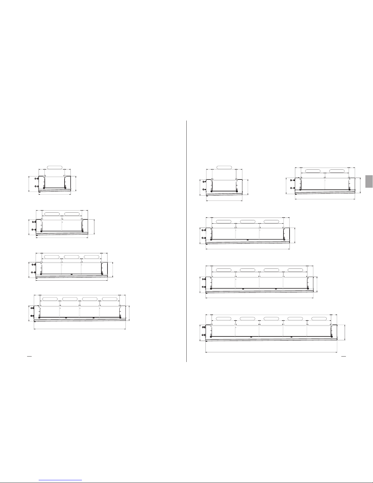
804
767
6004 300 300
6613
804
767
4804300 300
5412
804
767
3604300 300
4212
804
767
300 300
1812
776
748
300 300
1611
776
748
2004300 300
2611
776
748
3004300 300
3612
776
748
4004300 300
4612
804
767
2404300 300
3013
1004 FIX AGE
1002 FIX AGE 1002 FIXAGE
1002 FIX AGE 1000 FIXAGE 1002 FIXAGE
1002 FIX AGE 1000 FIXAGE 1000 FIXAGE 1002 FIX AGE
1204 FI XAGE
1202 FI XAGE 12 02 FIX AGE
1202 FI XAGE 12 00 FIX AGE 1202 FI XAGE
1202 FI XAGE 120 0 FIX AGE 12 00 FIX AGE 1202 FIX AGE
1202 FI XAGE
1200 F IXAGE 120 0 FIXA GE 120 0 FIX AGE 12 02 FIX AGE
Heat Exchange SolutionsThermoKey Manuel Technique TC Instruction et donnés technique
134133
FR
MT TC A DF FR 04 2017MT TC A DF FR 04 2017
DFX DFB DFN DFC Ø 560 mm
1X560
2X560
3X560
4X560
DFX DFB DFN DFC Ø 630 mm
1X630 2X630
3X630
4X630
5X630

1810
449
1656
50
661
1960
1896 FIXING
50
863
470
1808
1960
50
886
470
1808
1746 FI XAG E
1746 FI XAG E
1896 FIXAGE
Heat Exchange SolutionsThermoKey Manuel Technique TC Instruction et donnés technique
136135
FR
MT TC A DF FR 04 2017MT TC A DF FR 04 2017
DFX DFB DFN DFC
Ø 500 mm
Ø 560 mm
Ø 630 mm
TC 11. Données techniques
1
1
1
2
2
2
3
3
3
4
4
4
1
1
1
2
2
2
3
3
3
4
4
4
1
1
1
2
2
2
3
3
3
4
4
4
5
5
5
500
500
500
500
500
500
500
500
500
500
500
500
560
560
560
560
560
560
560
560
560
560
560
560
560
630
630
630
630
630
630
630
630
630
630
630
630
630
630
60,57
90,85
121,40
121,14
181,70
242,80
181,71
272,55
364,20
242,28
363,40
485,60
90,85
136,28
181,71
181,70
272,56
363,42
272,55
408,84
545,13
363,40
545,12
726,84
109,02
163,54
218,05
218,04
327,08
436,10
327,06
490,62
654,15
436,08
654,16
872,20
/
/
/
7,2
10,7
14,3
14,4
21,4
28,6
21,6
32,1
42,9
28,8
42,8
57,2
10,9
16,3
21,7
21,8
32,6
43,4
32,7
48,9
65,1
43,6
65,2
86,8
12,9
19,3
25,8
25,8
38,6
51,6
38,7
57,9
77,4
51,6
77,2
103,2
/
/
/
58,76
88,15
117,53
117,52
176,30
235,06
176,28
264,45
352,59
235,04
352,60
470,12
88,15
132,22
176,29
176,30
264,44
352,58
264,45
396,66
528,87
352,60
528,88
705,16
105,77
158,66
211,55
211,54
317,32
423,10
317,31
475,98
634,65
423,08
634,64
846,20
528,85
793,30
1057,75
12,7
19,1
25,4
25,4
38,2
50,8
38,1
57,3
76,2
50,8
76,4
101,6
19,1
28,6
38,1
38,2
57,2
76,2
57,3
85,8
114,3
76,4
114,3
76,4
114,4
152,4
22,9
34,3
45,7
45,8
68,6
91,4
68,7
102,9
137,2
182,8
114,5
171,5
228,5
104
118
131
190
216
241
274
312
352
358
409
462
148
168
198
257
297
348
361
425
488
467
553
632
169
192
226
287
333
392
401
474
546
516
615
705
638
770
875
104
118
131
190
216
241
274
312
352
358
409
462
148
168
198
257
297
348
361
425
488
467
553
632
169
192
226
287
333
392
401
474
546
516
615
705
/
/
/
DFX1504504
DFX1504506
DFX1504508
DFX2504504
DFX2504506
DFX2504508
DFX3504504
DFX3504506
DFX3504508
DFX4504504
DFX4504506
DFX4504508
DFX1564504
DFX1564506
DFX1564508
DFX2564504
DFX2564506
DFX2564508
DFX3564504
DFX3564506
DFX3564508
DFX4564504
DFX4564506
DFX4564508
DFX1634504
DFX1634506
DFX1634508
DFX2634504
DFX2634506
DFX2634508
DFX3634504
DFX3634506
DFX3634508
DFX4634504
DFX4634506
DFX4634508
/
/
/
DFB1504504
DFB1504506
DFB1504508
DFB2504504
DFB2504506
DFB2504508
DFB3504504
DFB3504506
DFB3504508
DFB4504504
DFB4504506
DFB4504508
DFB1564504
DFB1564506
DFB1564508
DFB2564504
DFB2564506
DFB2564508
DFB3564504
DFB3564506
DFB3564508
DFB4564504
DFB4564506
DFB4564508
DFB1634504
DFB1634506
DFB1634508
DFB2634504
DFB2634506
DFB2634508
DFB3634504
DFB3634506
DFB3634508
DFB4634504
DFB4634506
DFB4634508
DFB5634504
DFB5634506
DFB5634508
Mot.n°Dia
[mm]
MODÈLE
Surface
extérieure
[m2]
Surface
extérieure
[m2]
Volume
Intérieur
[dm3]
Volume
Intérieur
[dm3]
Poids
net
[kg]
Poids
net
[kg]
MODÈLE
DFX DFB PAS 4,5 mm
32
70
18x30
32
70
18x30
32
70
18X30

Heat Exchange SolutionsThermoKey Manuel Technique TC Instruction et donnés technique
138137
FR
MT TC A DF FR 04 2017MT TC A DF FR 04 2017
DFX DFB PITCH 10,0 mmDFX DFB PITCH 7,0 mm
1
1
1
2
2
2
3
3
3
4
4
4
1
1
1
2
2
2
3
3
3
4
4
4
1
1
1
2
2
2
3
3
3
4
4
4
5
5
5
500
500
500
500
500
500
500
500
500
500
500
500
560
560
560
560
560
560
560
560
560
560
560
560
560
630
630
630
630
630
630
630
630
630
630
630
630
630
630
DFX1507004
DFX1507006
DFX1507008
DFX2507004
DFX2507006
DFX2507008
DFX3507004
DFX3507006
DFX3507008
DFX4507004
DFX4507006
DFX4507008
DFX1567004
DFX1567006
DFX1567008
DFX2567004
DFX2567006
DFX2567008
DFX3567004
DFX3567006
DFX3567008
DFX4567004
DFX4567006
DFX4567008
DFX1637004
DFX1637006
DFX1637008
DFX2637004
DFX2637006
DFX2637008
DFX3637004
DFX3637006
DFX3637008
DFX4637004
DFX4637006
DFX4637008
/
/
/
39,84
59,76
79,68
79,68
119,52
159,36
119,52
179,28
239,04
159,36
239,04
318,72
59,76
89,64
119,53
119,52
179,28
239,06
179,28
268,92
358,59
239,04
358,56
478,12
71,72
107,57
143,43
143,44
215,14
286,86
215,16
322,71
430,29
286,88
430,28
573,72
/
/
/
7,2
10,7
14,3
14,4
21,4
28,6
21,6
32,1
42,9
28,8
42,8
57,2
10,9
16,3
21,7
21,8
32,6
43,4
32,7
48,9
65,1
43,6
65,2
86,8
12,9
19,3
25,8
25,8
38,6
51,6
38,7
57,9
77,4
51,6
77,2
103,2
/
/
/
102
115
127
186
210
234
268
304
341
351
399
448
144
164
192
248
289
331
352
412
470
455
537
609
165
187
219
277
323
372
390
460
526
502
596
679
/
/
/
38,97
58,45
77,94
77,94
116,90
155,88
116,91
175,35
233,82
155,88
233,80
311,76
58,45
87,68
116,91
116,90
175,36
233,82
175,35
263,04
350,73
233,80
350,72
467,64
70,14
105,22
140,29
140,28
210,44
280,58
210,42
315,66
420,87
280,56
420,88
561,16
350,70
526,10
701,45
102
115
127
186
210
234
268
304
341
351
399
448
144
164
192
248
289
331
352
412
470
455
537
609
165
187
219
277
323
372
390
460
526
502
596
679
620
746
842
DFB1507004
DFB1507006
DFB1507008
DFB2507004
DFB2507006
DFB2507008
DFB3507004
DFB3507006
DFB3507008
DFB4507004
DFB4507006
DFB4507008
DFB1567004
DFB1567006
DFB1567008
DFB2567004
DFB2567006
DFB2567008
DFB3567004
DFB3567006
DFB3567008
DFB4567004
DFB4567006
DFB4567008
DFB1637004
DFB1637006
DFB1637008
DFB2637004
DFB2637006
DFB2637008
DFB3637004
DFB3637006
DFB3637008
DFB4637004
DFB4637006
DFB4637008
DFB5637004
DFB5637006
DFB5637008
Mot.n°Dia
[mm]
MODÈLE
1
1
1
2
2
2
3
3
3
4
4
4
1
1
1
2
2
2
3
3
3
4
4
4
1
1
1
2
2
2
3
3
3
4
4
4
5
5
5
500
500
500
500
500
500
500
500
500
500
500
500
560
560
560
560
560
560
560
560
560
560
560
560
560
630
630
630
630
630
630
630
630
630
630
630
630
630
630
DFX1501004
DFX1501006
DFX1501008
DFX2501004
DFX2501006
DFX2501008
DFX3501004
DFX3501006
DFX3501008
DFX4501004
DFX4501006
DFX1001008
DFX1561004
DFX1561006
DFX1561008
DFX2561004
DFX2561006
DFX2561008
DFX3561004
DFX3561006
DFX3561008
DFX4561004
DFX4561006
DFX4561008
DFX1631004
DFX1631006
DFX1631008
DFX2631004
DFX2631006
DFX2631008
DFX3631004
DFX3631006
DFX3631008
DFX4631004
DFX4631006
DFX4631008
/
/
/
28,65
42,97
57,30
57,30
85,94
114,60
85,95
128,91
171,90
114,60
171,88
229,20
42,97
64,46
85,95
85,94
128,92
171,90
128,91
193,38
257,85
171,88
257,84
343,80
51,57
77,35
103,14
103,14
154,70
206,28
154,71
232,05
309,42
206,28
309,40
412,56
/
/
/
7,2
10,7
14,3
14,4
21,4
28,6
21,6
32,1
42,9
28,8
42,8
57,2
10,9
16,3
21,7
21,8
32,6
43,4
32,7
48,9
65,1
43,6
65,2
86,8
12,9
19,3
25,8
25,8
38,6
51,6
38,7
57,9
77,4
51,6
77,2
103,2
/
/
/
101
113
125
184
206
229
264
298
333
347
391
437
142
160
187
243
281
322
344
402
457
446
524
593
162
183
214
272
315
362
382
449
511
492
581
660
/
/
/
28,28
42,42
56,56
56,56
84,84
113,12
84,84
127,26
169,68
113,12
169,68
226,24
42,42
63,63
84,84
84,84
127,26
169,68
127,26
190,89
254,52
169,68
254,52
339,36
50,90
76,35
101,81
101,80
152,70
203,62
152,70
229,05
305,43
203,60
305,40
407,24
254,50
381,75
509,05
12,7
19,1
25,4
25,4
38,2
50,8
38,1
57,3
76,2
50,8
76,4
101,6
19,1
28,6
38,1
38,2
57,2
76,2
57,3
85,8
114,3
76,4
114,4
152,4
22,9
34,3
45,7
45,8
68,6
91,4
68,7
102,9
137,2
91,6
137,2
182,8
114,5
171,5
228,5
12,7
19,1
25,4
25,4
38,2
50,8
38,1
57,3
76,2
50,8
76,4
101,6
19,1
28,6
38,1
38,2
57,2
76,2
57,3
85,8
114,3
76,4
114,4
152,4
22,9
34,3
45,7
45,8
68,6
91,4
68,7
102,9
137,2
91,6
137,2
182,8
114,5
171,5
228,5
101
113
125
184
206
229
264
298
333
347
391
437
142
160
187
243
281
322
344
402
457
446
524
593
162
183
214
272
315
362
382
449
511
492
581
660
607
727
817
DFB1501004
DFB1501006
DFB1501008
DFB2501004
DFB2501006
DFB2501008
DFB3501004
DFB3501006
DFB3501008
DFB4501004
DFB4501006
DFB1001008
DFB1561004
DFB1561006
DFB1561008
DFB2561004
DFB2561006
DFB2561008
DFB3561004
DFB3561006
DFB3561008
DFB4561004
DFB4561006
DFB4561008
DFB1631004
DFB1631006
DFB1631008
DFB2631004
DFB2631006
DFB2631008
DFB3631004
DFB3631006
DFB3631008
DFB4631004
DFB4631006
DFB4631008
DFB5631004
DFB5631006
DFB5631008
Mot.n°Dia
[mm]
MODÈLE
Surface
extérieure
[m2]
Surface
extérieure
[m2]
Volume
Intérieur
[dm3]
Volume
Intérieur
[dm3]
Poids
net
[kg]
Poids
net
[kg]
MODÈLE
Surface
extérieure
[m2]
Surface
extérieure
[m2]
Volume
Intérieur
[dm3]
Volume
Intérieur
[dm3]
Poids
net
[kg]
Poids
net
[kg]
MODÈLE

PL
MT TC A DF PL 04 2017
Podręcznik techniczny - TC
SERIA DFX DFB DFN DFC
Chłodnice z podwójnym
wydmuchem powietrza
ORYGINALNY TEKST NINIEJSZEJ INSTRUKCJI JEST W
JĘZYKU WŁOSKIM
MT TC A DF PL 04 2017

Heat Exchange SolutionsThermoKey
Podręcznik techniczny - TC Instrukcje i dane techniczne
141140
PL
MT TC A DF PL 04 2017MT TC A DF PL 04 2017
NALEŻY UWAŻNIE PRZECZYTAĆ I ZROZUMIEĆ WSZYSTKIE
INFORMACJE ZAWARTE W INSTRUKCJI PRZED PROJEKTOWANIEM
I KAŻDORAZOWO PRZED WYKONANIEM WSZELKICH CZYNNOŚCI
PRZENOSZENIA, ROZPAKOWYWANIA, MONTAŻU, USTAWIANIA I
URUCHAMIANIA URZĄDZENIA. FIRMA THERMOKEY NIE PONOSI ŻADNEJ
ODPOWIEDZIALNOŚCI ZA SZKODY WYRZĄDZONE W STOSUNKU DO OSÓB
LUB MIENIA, POWSTAŁE W WYNIKU NIEPRZESTRZEGANIA WSKAZÓWEK
ZAWARTYCH W NINIEJSZYM DOKUMENCIE.
Oryginalna wersja tego podręcznika jest w języku włoskim i jest dostępna na stronie internetowej:
www.thermokey.com.
Tłumaczenie na język angielski jest wierną kopią oryginalnego dokumentu i jest ono dostępne na
stronie internetowej: www.thermokey.com.
Tłumaczenia na inne języki mogą zawierać błędy; w razie wątpliwości, zawsze odnieść się do
pierwotnej wersji w języku włoskim lub jej tłumaczenia na język angielski.
Thermokey S.p.A. System Zarządzania Jakością posiada certykat zgodnie z ISO 9001,
Thermokey S.p.A. System Zarządzania Środowiskowego posiada certykat zgodnie z ISO 14001)
oraz System Zarządzania Bezpieczeństwem posiada certykat zgodnie z OHSAS 18001.
Chłodnica z Podwójnym
Wydmuchem Powietrza
TC 1. ODNIESIENIA DO NORM I DYREKTYW
TC 2. ZAGROŻENIA
TC 3. OSTRZEŻENIA
TC 4. PRZEZNACZENIE
TC 5. KONTROLA, PRZEŁADUNEK I TRANSPORT
TC 6. INSTALACJA I URUCHOMIENIE
TC 7. OGÓLNA KONSERWACJA I KONTROLA
TC 8. SCHEMATY OKABLOWANIA GRZAŁEK ELEKTRYCZNYCH
TC 9. SCHEMATY OKABLOWANIA WENTYLATORÓW
TC 10. WYMIARY
TC 11. DANE TECHNICZNE
STRESZCZENIE
142
142
143
144
144
145
148
150
155
159
163

Heat Exchange SolutionsThermoKey
Podręcznik techniczny - TC Instrukcje i dane techniczne
143142
PL
MT TC A DF PL 04 2017MT TC A DF PL 04 2017
Niebezpieczeństwo porażenia prądem. Produkt jest wyposażony w elektryczne wentylatory oraz welementy elektrycznego
systemu odtajania z nominalnym niskonapięciem roboczym trzyfazowym AC lub jednofazowym. Przewody zasilania
elektrycznego będą posiadały systemy zabezpieczenia przeciwporażeniowe oraz urządzenia ochronne wymagane prawem.
Ryzyko oparzenia. W produktach wyposażonych w system odtajania elektrycznego temperatura powierzchni zewnętrznej
obudowy może sięgać około 350°C, jeśli jest pozostawiona bez kontroli.
Ryzyko rozcięcia. Wewnętrzny wymiennik ciepła jest wykonany z metalowych lamel z niechronionymi ostrymi
krawędziami. Osłona jest wykonana z metalowych komponentów, które mogą posiadać niechronione ostre krawędzie.
Zagrożenie wynikające z ruchomych części. Produkt posiada wmontowane elektryczne wentylatory, które są wyposażone
w ochronną kratę wymaganą prawem. W przypadku niektórych produktów możliwy jest specjalny dostęp do ruchomych
części (łopaty wentylatora) z obszaru niechronionego. Przed próbą dostępu należy się upewnić, że ruchome części nie
stanowią zagrożenia dla osoby obsługującej.
Niebezpieczeństwo zgniecenia kończyn lub osób. W czasie przeładunki, transportu oraz instalacji, obsługi i konserwacji
należy zwracać szczególną uwagę na oznaczoną wagę każdego produktu wcelu ochrony przez ewentualnym wywróceniem
lub niebezpiecznymi upadkami na osoby obsługujące.
Niebezpieczeństwo spadających przedmiotów. Produkty posiadają wmontowane drzwi, tace lub metalowe osłaniające
części, które w czasie instalacji lub konserwacji mogą być odinstalowane przez usunięcie śrub mocujących; należy
zachować właściwe środki ostrożności.
TC 2. Zagrożenia
TC 1. Odniesienia do norm i dyrektyw
Produkt opisany w niniejszym podręczniku jest zgodny z:
DYREKTYWĄ MASZYNOWĄ 2006/42/EC
DYREKTYWĄ NISKONAPIĘCIOWĄ 2014/35/EU
DYREKTYWĄ ZGODNOŚCI ELEKTROMAGNETYCZNEJ 2014/30/EU
DYREKTYWĄ W SPRAWIE URZĄDZEŃ CIŚNIENIOWYCH (PED) 2014/68/UE
DYREKTYWĄ DOTYCZĄCĄ SPRAWNOŚCI ENERGETYCZNEJ (ERP) 2009/125/EC
TC 3. Ostrzeżenia
TC 3.1
Zawartość Podręcznika Technicznego Produktu:
INSTRUKCJE DOTYCZĄCE BEZPIECZNEGO ZASTOSOWANIA (IG)
INSTRUKCJE DOTYCZĄCE PRZEŁADUNKU I ROZPAKOWYWANIA (IM)
INSTRUKCJE I DANE TECHNICZNE (TC)
SZCZEGÓŁOWE INSTRUKCJE UŻYTKOWANIA I KONSERWACJI (IS)
TC 3.2
Niniejszy podręcznik odnosi się do sekcji TC, nazwanej INSTRUKCJE I DANE TECHNICZNE Podręcznika
Technicznego Produktu. W celu uzyskania wszelkich informacji nieobjętych niniejszym podręcznikiem należy odnieść
się do innych sekcji (IG-IM-IS), a w przypadku wątpliwości skontaktować się z Producentem.
TC 3.3
Niniejszy podręcznik stanowi integralną część urządzeń DFX DFB DFN oraz DFC, dlatego musi być przechowywany
przez cały okres użytkowania urządzenia.
TC 3.4
Jakakolwiek dodatkowa dokumentacja techniczna odnosząca się do niestandardowych produktów jest dołączona do
niniejszego podręcznika i staje się jego integralną częścią oraz jest oznaczona specjalnym kodem umieszczonym w
dokumentacji przewozowej.
TC 3.5
Produkt opisany w niniejszym podręczniku jest uważany za maszynę nieukończoną dlatego nieużyteczną wformie
dostarczonej, jednak stanowi komponent systemów klimatyzacji i chłodzenia i musi być zainstalowany iuruchomiony
przez wykwalifikowaną obsługę (patrz rozdział odnoszący się do instalacji i uruchomienia).
TC 3.6
Każdy produkt jest dostarczany z Deklaracją Własności Użytkowych EC.
TC 3.7
Dodatkowa dokumentacja produktu składająca się z katalogów, przewodników i biuletynów technicznych
pochodzi bezpośrednio od Thermokey i jest dostępna na stronie internetowej www.thermokey.com.
KATALO GI – http://www.thermokey.com/Cataloghi.aspx
PODRĘCZNIKI – http://www.thermokey.com/Manuali.aspx

Heat Exchange SolutionsThermoKey
Podręcznik techniczny - TC Instrukcje i dane techniczne
145144
PL
MT TC A DF PL 04 2017MT TC A DF PL 04 2017
TC 4. Przeznaczenie
TC 4.1
Urządzenie powinno być wykorzystywane wyłącznie do celu określonego poniżej, w innym przypadku jego stosowanie
będzie uważane za nieprawidłowe i zwolni producenta z jakiejkolwiek odpowiedzialności.
TC 4.2
Chłodnice z podwójnym wydmuchem powietrza serii DFX DFN DFB i DFC są zaprojektowane do użytku we
wszystkich sektorach spożywczych w średniej i dużej wielkości pomieszczeniach chłodniczych lub magazynach
głębokiego chłodzenia, w celu przechowywania świeżych i zamrożonych towarów, jak również w celu chłodzenia i
klimatyzowania średnich i dużych pomieszczeń przetwórczych. Wszystkie urządzenia standardowe są wyposażone w
wysokowydajne wentylatory dla optymalnego rozprowadzania powietrza.
TC 4.3
Urządzenie standardowe jest wyposażone w wentylatory o zerowym sprężu dyspozycyjnym
TC 4.4
W przypadku wątpliwości dotyczących przeznaczenia, należy skontaktować się z producentem.
TC 5. Kontrola, przeładunek i transport
TC 5.1
Po przyjęciu urządzenia należy sprawdzić czy opakowanie oraz produkt są w nienaruszonym stanie; natychmiast
powiadomić przewoźnika o wszelkich możliwych uszkodzeniach. Opakowanie jest dopasowane do rodzaju produktu
oraz właściwego środka transportu i przeładunku.
TC 5.2
W czasie transportu i przeładunku urządzenia należy unikać niewłaściwego oraz niespełniającego wymagań nacisku
na zapakowany produkt, należy zachować zgodność ze wszystkimi wskazaniami i zawsze przechowywać urządzenie w
pozycji pokazanej na rysunku (patrz rys.1).
TC 5.3
W czasie transportu i przeładunku zapakowanego produktu należy zastosować właściwą ochronę, by uniknąć urazu ze
strony części opakowania, takich jak gwoździe, deski lub kartony oraz ze strony części urządzenia, takich jak lamele
lub części obudowy ( patrz DPI Podręcznik Techniczny Sekcja I rozdział IG 6).
TC 5.4
Należy rozpakować urządzenie możliwie najbliżej miejsca instalacji ( patrz również rozdział Instalacja i Uruchomienie).
Zasadniczo, urządzenie nie powinno być transportowane lub przeładowywane bez oryginalnego opakowania.
TC 5.5
W czasie przeładunku rozpakowanego urządzenia do instalacji należy stosować ochronę w celu zapobiegania urazom ze
strony ostrych krawędzi, takich jak lamele lub części obudowy (patrz DPI Podręcznik Techniczny Sekcja I rozdział IG 6).
TC 6.1
Instalacja i uruchamianie urządzenia powinno być przeprowadzane przez eksperta i wykwalifikowany personel. W
celu zamocowania postępować zgodnie ze schematem pokazanym na rysunku (patrz rys.2).
TC 6.2
Dla właściwej cyrkulacji powietrza należy upewnić się, że obszar instalacji zapewnia odpowiednią ilość wolnej
przestrzeni oraz kanały do zapewnienia właściwego dopływu powietrza i wyrzutu powietrza z urządzenia.
Wprzeciwnym razie, zagwarantowanie deklarowanych osiągów może być niemożliwe i mogą wystąpić uszkodzenia.
Należy odblokować wlot i wylot powietrza do wentylatorów i wymienników ciepła (patrz rys.3).
TC 6.3
Upewnić się, czy konstrukcje podpierające i urządzenia kotwiące odpowiadają wadze i formie urządzenia (patrz
rozdziały Wymiary i Dane Te chniczne).
TC 6.4
Zamocować urządzenie we wszystkich punktach mocujących (patrz rozdział Wymiary) odpowiednimi kotwami
zgodnie z całkowitą osiągalną wagą (wagą netto urządzenia, wagą czynnika chłodniczego, wagą lodu nagromadzonego
na wymienniku ciepła, masą nagromadzoną na tacach ociekowych).
TC 6.5
Urządzenie nie jest zaprojektowane do dźwigania dodatkowego obciążenia.
TC 6.6
W modelach z opcją odtajania elektrycznego należy zapewnić odpowiednią przestrzeń w celu wymiany grzałek w
wymiennikach ciepła.
Rys.1 - Dla bezpiecznego przeładunku widły zawsze
powinny wystawać poza skrzyniopaletę.
TC 6. Instalacja i uruchomienie

Heat Exchange SolutionsThermoKey
Podręcznik techniczny - TC Instrukcje i dane techniczne
147146
PL
MT TC A DF PL 04 2017MT TC A DF PL 04 2017
TC 6.7
W obszarze działania wielu urządzeń nie należy przeprowadzać zmiennych cyklów odtajania dla uniknięcia
nadmiarowego gromadzenia się lodu na wymiennikach ciepła.
TC 6.8
Sprawdzić, czy linia zasilająca jest zgodna z wymogami urządzenia znajdującymi się na tabliczce danych technicznych.
TC 6.9
Przed podłączeniem urządzenia należy sprawdzić obecność elementów odłączających i rozłączających na linii
zasilającej, zabezpieczenia przeciwporażeniowe, ochronę urządzenia oraz inne elementy wymagane prawem.
Standardowe modele są wyposażone w skrzynki przyłączeniowe do zasilania wentylatorów oraz grzałek (wmodelach
z elektrycznym odtajaniem).
TC 6.10
Jeśli do wentylatorów stosowane są regulatory prędkości, należy sprawdzić ich kompatybilność. Regulatory
niekompatybilne mogą wytwarzać hałas i uszkodzić wentylatory. Producent nie gwarantuje wskazanych osiągów
urządzeń wyposażonych w regulatory prędkości.
TC 6.11
Należy się upewnić, że rodzaj środka chłodniczego jest odpowiedni dla osiągów urządzenia. Przy podłączaniu obiegu
chłodzącego należy unikać odkształcenia kapilar oraz zmiany usytuowania dystrybutora lub kolektorów.
TC 6.12
Należy się upewnić, że wartości graniczne warunków roboczych (wilgotność, temperatura oraz ciśnienie) spełniają
określone wymogi wybranego produktu.
TC 6.13
Dla urządzeń z elektrycznym odtajaniem, zależnie od typu chłodni, należy prawidłowo określić czas iliczbę cykli
odtajania. Cykl odtajania musi być sterowany wyłącznikiem czasowym, a czujniki temperatury powinny przerywać
cykl jedynie w sytuacji ewentualnego przegrzania. Czujniki powinny być umieszczane w możliwie najchłodniejszych
częściach wymiennika ciepła (w miejscach największego nagromadzenia szronu) wo ddaleniu od elementów grzewczych.
TC 6.14
Należy się upewnić, że pod koniec każdego cyklu odtajania (elektryczność, gorący gaz lub ciepły glikol), bloki
lamelowe, wewnętrzna taca ociekowa oraz system odprowadzający są czyste. Jeśli to konieczne, należy skorygować
czas trwania i liczbę cykli odtajania. Nagromadzenie szronu prowadzi do szkodliwego zjawiska odkładania się lodu,
które może powodować uszkodzenie lub awarię wymiennika ciepła.
TC 6.15
Należy zainstalować odpowiednie syfony na przewodzie odprowadzania i sprawdzać ich skuteczność we wszystkich
temperaturach roboczych. W pomieszczeniach o niskiej temperaturze, poniżej punktu zamarzania, wilgoć zzewnątrz przedostaje
się do przewodu odprowadzającego. Jeśli nie jest wyposażony w syfony, doprowadza do nagromadzenia szkodliwego lodu.
TC 6.16
Dostęp do zainstalowanego urządzenia w celu jakiejkolwiek interwencji, powinien być zarezerwowany wyłącznie dla
doświadczonego personelu, szczególnie przeszkolonego w obsłudze systemu, zgodnie z obowiązującymi przepisami.
rys.2 – Kolejność mocowań:
a) Zdjąć wierzch skrzyniopalety.
b) Możliwa prosta kolejność instalacji jedynie dla modeli standardowych z maksymalną liczbą dwóch wentylatorów,
należy również zdjąć boki oraz końce skrzyniopalety.
c) Unieść i ustawić.
d) Zamocować urządzenie we wszystkich właściwych punktach (patrz rozdział Wymiary) za pomocą odpowiednich
kotew, zgodnie z całkowitą wagą (waga netto urządzenia, waga czynnika chłodniczego, waga zgromadzonego lodu na
wymienniku ciepła, masa nagromadzona na tacach ociekowych).
e) Zdjąć skrzyniopaletę i uchwyty transportowe.
f) Wyjąć spód skrzyniopalety oraz uchwyty transportowe.
c) d)
c) d)
a) b)
e) f)
a)
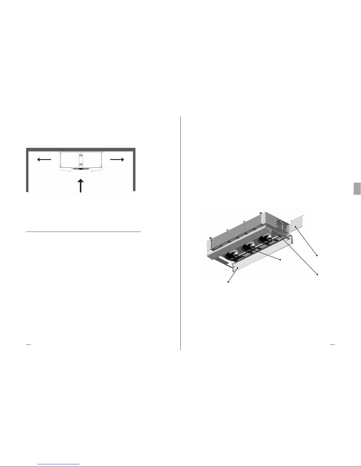
Heat Exchange SolutionsThermoKey
Podręcznik techniczny - TC Instrukcje i dane techniczne
149148
PL
MT TC A DF PL 04 2017MT TC A DF PL 04 2017
TC 7. Ogólna konserwacja i kontrola
TC 7.1
Przed przeprowadzeniem prac konserwacyjnych należy się upewnić, że źródło zasil ania zostało odłączone: części
elektryczne mogą być podłączone do sterowników automatycznych. Wszystkie prace konserwacyjne powinny być
przeprowadzane przez wykwalifikowany i doświadczony personel.
TC 7.2
Urządzenie składa się głównie z: lamelowych wymienników ciepła, ramy konstrukcyjnej w metalowych panelach,
metalowych pokryw, zewnętrznych tac ociekowych oraz wentylatorów. W urządzeniach z elektrycznym odtajaniem,
grzałki w obudowie ze stali nierdzewnej z wulkanizowanymi złączami z elementami blokującymi, które zapobiegają
przemieszczeniu (patrz rys.4) znajdują się w wymienniku i na tacach ociekowych.
TC 7.3
Okresowo należy sprawdzać miejsca mocowań urządzenia, połączenia elektryczne oraz połączenia zprzewodami
czynnika chłodniczego.
TC 7.4
Należy zapewnić okresowe czyszczenie obudowy oraz wymiennika za pomocą odpowiednich detergentów lub wody z mydłem
o obojętnym pH. Nie stosować agresywnych środków czyszczących, rozpuszczalników, kwasów lub roztworów zasadowych
zawierających chlor lub amoniak. Unikać stosowania materiałów ściernych. W przypadku stosowania środków odkażających
należy sprawdzić ich zgodność z materiałami. W przypadku wątpliwości należy skontaktować się z Producentem.
TC 7.5
Sprawdzić efektywność odtajania. W przypadku urządzeń z elektrycznym odtajaniem, należy okresowo sprawdzać
działanie wszystkich grzałek. Producent nie odniesie się w żaden sposób do szkód oraz wad spowodowanych przez
rys.3 – Minimalna odległość od ścian min. 1m
Uwaga: Nie blokować wlotu lub wylotu powietrza wentylatorów oraz wymienników ciepła.
<< MIN. 1m >> << MIN. 1m >>
niewykryte awarie (np. szkodliwe nagromadzenie lodu).
TC 7.6
Zapewnić wymianę uszkodzonych grzałek. Zwrócić szczególną uwagę w czasie instalacji, by zapobiec uszkodzeniu
wulkanizowanych izolacji; prawidłowo przywrócić wszystkie połączenia (patrz załączone schematy) oraz wszystkie
systemy blokujące, które zabezpieczają przed przemieszczeniem w czasie działania.
TC 7.7
Terminy kontroli i konserwacji zależą od typu grzałek, dlatego powinny być określone przez wykwalifikowany i
doświadczony personel.
TC 7.8
W przypadku wszelkich działań na urządzeniach nieopisanych w niniejszym podręczniku należy skontaktować się z
Producentem.
Rysunek 4 – Komponenty
a) Boczne osłony wyposażone są w zdejmowane zawiasy dla ułatwienia dostępu do przedziału kolektorów na czas
instalacji i konserwacji. Zamknięcie osłon jest zabezpieczone śrubami.
b) Osłony są zdejmowane, by zapewnić pełny dostęp do przedziału kolektorów.
c) Tace ociekowe są na zawiasach dla łatwego dostępu do wewnętrznej tacy ociekowej, co pozwala na wymianę grzałek
lub czyszczenie. Mogą być odinstalowane, jeśli wymagają wymiany.
d) Każdy wentylator jest wyposażony w konstrukcyjną siatkę ochronną, co pozwala na wymianę od zewnątrz.
WEWNĘTRZNA
TACA OCIEKOWA
DEMONTOWALNA
OSŁONA BOCZNA
ZEWNĘTRZNA
TACA OCIEKOWA
WENTYLATOR

Heat Exchange SolutionsThermoKey
Podręcznik techniczny - TC Instrukcje i dane techniczne
151150
PL
MT TC A DF PL 04 2017MT TC A DF PL 04 2017
TC 8. Schemat okablowania i moc
znamionowa grzałek elektrycznych
TC 8.1
Obudowa każdego urządzenia jest wyposażona w zacisk uziemiający (PE) z etykietą identyfikacyjną.
Obowiązkowe jest podłączenie zacisku uziemiającego urządzenia do zewnętrznego systemu ochronnego lub uziemienia.
TC 8.2
Obowiązkowe jest stosowanie zabezpieczeń przeciwporażeniowych oraz nadprądowych na przewodach zasilających
grzałek.
TC 8.3
Należy okresowo sprawdzać efektywność grzałek by zapobiec nagromadzeniu niebezpiecznego lodu na urządzeniu w
wyniku niewykrytych usterek.
DFX DFB DFN DFC Ø 500 mm 04 RR
LINIA ZASILAJĄCA ~3 400V 50-60HZ
POŁĄCZENIE W GWIAZDĘ Z PRZEWODEM
ZEROWYMT
Moc bloku
Moc tacy ociekowej
Moc całkowita
3400
1700
5100
6800
3400
10200
10200
5100
15300
13600
6800
20400
150 45 04
150 70 04
150 10 04
250 45 04
250 70 04
250 10 04
350 45 04
350 70 04
350 10 04
450 45 04
450 70 04
450 10 04
MODELE
DFX DFB DFN DFC
(W)
(W)
(W)
HTH1
HTH2
HTH3
HTH4
HTL1 HTL3HTL2 HTL4
PE
HTH = grzałki dużej mocy (*) HTL = grzałki małej mocy (*)
(*) grzałka dużej mocy HTH posiada dwukrotną moc grzałki małej mocy HTL
Moc bloku
Moc tacy ociekowej
Moc całkowita
5950
1700
7650
11900
3400
15300
17850
5100
22950
23800
6800
30600
150 45 08
150 70 08
150 10 08
250 45 08
250 70 08
250 10 08
350 45 08
350 70 08
350 10 08
450 45 08
450 70 08
450 10 08
MODELE
DFX DFB DFN DFC
(W)
(W)
(W)
Moc bloku
Moc tacy ociekowej
Moc całkowita
3400
1700
5100
6800
3400
10200
10200
5100
15300
13600
6800
20400
150 45 06
150 70 06
150 10 06
250 45 06
250 70 06
250 10 06
350 45 06
350 70 06
350 10 06
450 45 06
450 70 06
450 10 06
MODELE
DFX DFB DFN DFC
(W)
(W)
(W)
DFX DFB DFN DFC Ø 500 mm 06 RR
DFX DFB DFN DFC Ø 500 mm 08 RR
HTH = grzałki dużej mocy (*) HTL = grzałki małej mocy (*)
(*) grzałka dużej mocy HTH posiada dwukrotną moc grzałki małej mocy HTL
HTH = grzałki dużej mocy (*) HTL = grzałki małej mocy (*)
(*) grzałka dużej mocy HTH posiada dwukrotną moc grzałki małej mocy HTL
LINIA ZASILAJĄCA ~3 400V 50-60HZ
POŁĄCZENIE W GWIAZDĘ Z PRZEWODEM
ZEROWYM
LINIA ZASILAJĄCA ~3 400V 50-60HZ
POŁĄCZENIE W GWIAZDĘ Z PRZEWODEM
ZEROWYM
HTH1
HTL1
HTL3
HTL2
HTL4
HTH2
HTL5 HTL7HTL6 HTL8
HTH1
HTH3
HTL2
HTL1
HTH6
HTH5
HTL3 HTL5HTL4 HTL6
HTH4HTH2
PE
PE

Heat Exchange SolutionsThermoKey
Podręcznik techniczny - TC Instrukcje i dane techniczne
153152
PL
MT TC A DF PL 04 2017MT TC A DF PL 04 2017
DFX DFB DFN DFC Ø 560 mm 04 RR
DFX DFB DFN DFC Ø 560 mm 06 RR
LINIA ZASILAJĄCA ~3 400V 50-60HZ
POŁĄCZENIE W GWIAZDĘ Z PRZEWODEM
ZEROWYM
LINIA ZASILAJĄCA ~3 400V 50-60HZ
POŁĄCZENIE W GWIAZDĘ Z PRZEWODEM
ZEROWYM
HTH1 HTH2
HTL1 HTL3
HTL2 HTL4
HTL5 HTL7HTL6 HTL8
HTH1 HTH4
HTH2 HTH5
HTH3 HTH6
HTL1 HTL2
HTL3 HTL5HTL4 HTL6
PE
PE
Moc bloku
Moc tacy ociekowej
Moc całkowita
3400
1700
5100
6800
3400
10200
10200
5100
15300
13600
6800
20400
156 45 04
156 70 04
156 10 04
256 45 04
256 70 04
256 10 04
356 45 04
356 70 04
356 10 04
456 45 04
456 70 04
456 10 04
MODELE
DFX DFB DFN DFC
(W)
(W)
(W)
HTH = grzałki dużej mocy (*) HTL = grzałki małej mocy (*)
(*) grzałka dużej mocy HTH posiada dwukrotną moc grzałki małej mocy HTL
Moc bloku
Moc tacy ociekowej
Moc całkowita
5950
1700
7650
11900
3400
15300
17850
5100
22950
23800
6800
30600
156 45 06
156 70 06
156 10 06
256 45 06
256 70 06
256 10 06
356 45 06
356 70 06
356 10 06
456 45 06
456 70 06
456 10 06
MODELE
DFX DFB DFN DFC
(W)
(W)
(W)
HTH = grzałki dużej mocy (*) HTL = grzałki małej mocy (*)
(*) grzałka dużej mocy HTH posiada dwukrotną moc grzałki małej mocy HTL
DFX DFB DFN DFC Ø 630 mm 04 RR
LINIA ZASILAJĄCA ~3 400V 50-60HZ
POŁĄCZENIE W GWIAZDĘ Z PRZEWODEM
ZEROWYM
LINIA ZASILAJĄCA ~3 400V 50-60HZ
POŁĄCZENIE W GWIAZDĘ Z PRZEWODEM
ZEROWYM
Moc bloku
Moc tacy ociekowej
Moc całkowita
8500
1700
10200
17000
3400
20400
25500
5100
30600
34000
6800
40800
156 45 08
156 70 08
156 10 08
256 45 08
256 70 08
256 10 08
356 45 08
356 70 08
356 10 08
456 45 08
456 70 08
456 10 08
MODELE
DFX DFB DFN DFC
(W)
(W)
(W)
HTH = grzałki dużej mocy (*) HTL = grzałki małej mocy (*)
(*) grzałka dużej mocy HTH posiada dwukrotną moc grzałki małej mocy HTL
HTH = grzałki dużej mocy (*) HTL = grzałki małej mocy (*)
(*) grzałka dużej mocy HTH posiada dwukrotną moc grzałki małej mocy HTL
DFX DFB DFN DFC Ø 560 mm 08 RR
HTH1 HTH5
HTL2 HTL4
HTH2 HTH6
HTH3
HTL3
HTH4
HTH7
HTL1
HTH8
HTL5 HTL7HTL6 HTL8
PE
HTH1
HTL2
HTL1
HTH2
HTL4
HTL3
HTL5 HTL7HTL6 HTL8
PE
Moc bloku
Moc tacy ociekowej
Moc całkowita
3680
1840
5520
7360
3680
11040
11040
5520
16560
14720
7360
22080
18400
9200
27600
163 45 04
163 70 04
163 10 04
263 45 04
263 70 04
263 10 04
363 45 04
363 70 04
363 10 04
463 45 04
463 70 04
463 10 04
563 45 04
563 70 04
563 10 04
MODELE
DFX DFB DFN DFC
(W)
(W)
(W)

Heat Exchange SolutionsThermoKey
Podręcznik techniczny - TC Instrukcje i dane techniczne
155154
PL
MT TC A DF PL 04 2017MT TC A DF PL 04 2017
DFX DFB DFN DFC Ø 630 mm 06 RR
DFX DFB DFN DFC Ø 630 mm 08 RR
HTH = grzałki dużej mocy (*) HTL = grzałki małej mocy (*)
(*) grzałka dużej mocy HTH posiada dwukrotną moc grzałki małej mocy HTL
HTH = grzałki dużej mocy (*) HTL = grzałki małej mocy (*)
(*) grzałka dużej mocy HTH posiada dwukrotną moc grzałki małej mocy HTL
Moc bloku
Moc tacy ociekowej
Moc całkowita
9200
1840
11040
18400
3680
22080
27600
5520
33120
36800
7360
44160
46000
9200
55200
163 45 08
163 70 08
163 10 08
263 45 08
263 70 08
263 10 08
363 45 08
363 70 08
363 10 08
463 45 08
463 70 08
463 10 08
563 45 08
563 70 08
563 10 08
MODELE
DFX DFB DFN DFC
(W)
(W)
(W)
Moc bloku
Moc tacy ociekowej
Moc całkowita
6440
1840
8280
12880
3680
16560
19320
5520
24840
25760
7360
33120
32200
9200
41400
163 45 06
163 70 06
163 10 06
263 45 06
263 70 06
263 10 06
363 45 06
363 70 06
363 10 06
463 45 06
463 70 06
463 10 06
563 45 06
563 70 06
563 10 06
MODELE
DFX DFB DFN DFC
(W)
(W)
(W)
HTH1 HTH5
HTL2 HTL4
HTH2 HTH6
HTH3
HTL3
HTH4
HTH7
HTL1
HTH8
HTL5 HTL7HTL6 HTL8
PE
HTH1 HTH4
HTH2 HTH5
HTH3 HTH6
HTL1 HTL2
HTL3 HTL5HTL4 HTL6
PE
LINIA ZASILAJĄCA ~3 400V 50-60HZ
POŁĄCZENIE W GWIAZDĘ Z PRZEWODEM
ZEROWYM
LINIA ZASILAJĄCA ~3 400V 50-60HZ
POŁĄCZENIE W GWIAZDĘ Z PRZEWODEM
ZEROWYM
TC 9. Schematy okablowania i poboru
mocy wentylatorów
TC 9.1
Obudowa każdego urządzenia jest wyposażona w zacisk uziemiający (PE9 z etykietą identyfikacyjną). Należy
podłączyć zacisk uziemiający urządzenia do zewnętrznego systemu ochronnego lub uziemienia.
TC 9.2
W urządzeniach z okablowanymi wentylatorami obowiązkowe jest połączenie przewodów ochronnych wentylatorów z
systemem uziemienia ochronnego.
TC 9.3
Wymagane jest stosowanie systemów przeciwporażeniowych oraz zabezpieczeń nadprądowych na liniach zasilania
wentylatorów. Wentylatory są wyposażone w wyłączniki termiczne wbudowane w uzwojenie silnika. Należy podłączyć
wyłączniki termiczne w celu zabezpieczenia silnika przed przegrzaniem. Trzeba zauważyć, że przegrzanie może nie
być bezpośrednio związane z prądem przetężeniowym..
Istotne jest, że wyłącznik termiczny zamyka się bez ręcznego resetu, kiedy temperatura spada.
TC 9.4
Należy ściśle przestrzegać schematów okablowania, by zapobiec uszkodzeniu wentylatorów (a,b,c,d,e).
TC 9.5
Dla modeli z niestandardowymi wentylatorami należy odnieść się do szablonów i poboru mocy wskazanych w
arkuszach informacji uzupełniających oraz tabliczce znamionowej.
TC 9.6
Przed użyciem systemów sterowania prędkością wentylatora należy sprawdzić ich kompatybilność zwentylatorami.
Niekompatybilne systemy mogą generować hałas i powodować uszkodzenia. Producent nie odpowiada za wadliwe
działanie urządzeń wyposażonych w sterowniki prędkości nieokreślone w ofercie.

Heat Exchange SolutionsThermoKey
Podręcznik techniczny - TC Instrukcje i dane techniczne
157156
PL
MT TC A DF PL 04 2017MT TC A DF PL 04 2017
a) Schematy połączeń wentylatora standardowego
b) Wentylator – połączenie w trójkąt (dużej prędkości) c) Wentylator – połączenie w gwiazdę (małej prędkości)
d) Schemat zespołu zacisków głównej szafki elektrycznej od 1 do 5 wentylatorów
Połączenie równoległe zasilania oraz czujniki termiczne połączone szeregowo (gotowe do działania).
Możliwe połączenie jednoprzewodowe ze zdejmowaną zworką.

547
250 250
577
1004 FIXING
1511
547
250 250
577
2004 FIXING
2511
547
250 250
577
3004
2002 FIXING
1002 FIXING
3511
Heat Exchange SolutionsThermoKey
Podręcznik techniczny - TC Instrukcje i dane techniczne
159158
PL
MT TC A DF PL 04 2017MT TC A DF PL 04 2017
1
2
3
4
1
2
3
4
1
2
3
4
5
500
500
500
500
560
560
560
560
630
630
630
630
630
LICZBA WENTYLATORÓW
ŚREDNICA
NOMINALNA
0,77
1,54
2,31
3,08
1,05
2,10
3,15
4,20
1,25
2,50
3,75
5,00
6,25
1,7
3,4
5,1
6,8
2,2
4,4
6,6
8,8
2,48
4,96
7,44
9,92
12,4
DUŻA PRĘDKOŚĆ
KW A
0,49
0,98
1,47
1,96
0,58
1,16
1,74
2,32
0,84
1,68
2,52
3,36
4,20
0,84
1,68
2,52
3,36
1,1
2,2
3,3
4,4
1,42
2,84
4,26
5,68
7,10
KW A
MAŁA PRĘDKOŚĆ
e) Nominalny pobór mocy standardowego wentylatora
TC 10. Wymiary
DFX DFB DFN DFC Ø 500 mm
1X500
2X500
3X500
4X500
547
4004250 250
577
4511
2002 FIXING2002 FIXING

776
748
300 300
1004 FIXING
1611
776
748
2004300 300
1002 FIXING 1002 FIXING
2611
776
748
3004300 300
1002 FIXING 1000 FIXING 1002 FIXING
3612
776
748
4004300 300
1002 FIXING 1000 FIXING 1000 FIXING 1002 FIXING
4612
804
767
2404300 300
1202 FIXING 1202 FIXING
3013
Heat Exchange SolutionsThermoKey
Podręcznik techniczny - TC Instrukcje i dane techniczne
161160
PL
MT TC A DF PL 04 2017MT TC A DF PL 04 2017
DFX DFB DFN DFC Ø 560 mm
1X560
2X560
3X560
4X560
DFX DFB DFN DFC Ø 630 mm
804
767
300 300
1204 FIXING
1812
1X630 2X630
804
767
3604300 300
1202 FIXING 1200 FIXING 1202 FIXING
4212
3X630
804
767
4804300 300
1202 FIXING 1200 FIXING 1200 FIXING 1202 FIXING
5412
4X630
804
767
6004 300 300
1202 FIXING 1200 FIXING 1200 FIXING 1200 FIXING 1202 FIXING
6613
5X630

1810
449
1656
50
661
1746 FIXING
1960
1896 FIXING
50
863
470
1808
1960
1896 FIXING
50
886
470
1808
Heat Exchange SolutionsThermoKey
Podręcznik techniczny - TC Instrukcje i dane techniczne
163162
PL
MT TC A DF PL 04 2017MT TC A DF PL 04 2017
DFX DFB DFN DFC
Ø 500 mm
Ø 560 mm
Ø 630 mm
TC 11. Dane techniczne
1
1
1
2
2
2
3
3
3
4
4
4
1
1
1
2
2
2
3
3
3
4
4
4
1
1
1
2
2
2
3
3
3
4
4
4
5
5
5
500
500
500
500
500
500
500
500
500
500
500
500
560
560
560
560
560
560
560
560
560
560
560
560
560
630
630
630
630
630
630
630
630
630
630
630
630
630
630
60,57
90,85
121,40
121,14
181,70
242,80
181,71
272,55
364,20
242,28
363,40
485,60
90,85
136,28
181,71
181,70
272,56
363,42
272,55
408,84
545,13
363,40
545,12
726,84
109,02
163,54
218,05
218,04
327,08
436,10
327,06
490,62
654,15
436,08
654,16
872,20
/
/
/
7,2
10,7
14,3
14,4
21,4
28,6
21,6
32,1
42,9
28,8
42,8
57,2
10,9
16,3
21,7
21,8
32,6
43,4
32,7
48,9
65,1
43,6
65,2
86,8
12,9
19,3
25,8
25,8
38,6
51,6
38,7
57,9
77,4
51,6
77,2
103,2
/
/
/
58,76
88,15
117,53
117,52
176,30
235,06
176,28
264,45
352,59
235,04
352,60
470,12
88,15
132,22
176,29
176,30
264,44
352,58
264,45
396,66
528,87
352,60
528,88
705,16
105,77
158,66
211,55
211,54
317,32
423,10
317,31
475,98
634,65
423,08
634,64
846,20
528,85
793,30
1057,75
12,7
19,1
25,4
25,4
38,2
50,8
38,1
57,3
76,2
50,8
76,4
101,6
19,1
28,6
38,1
38,2
57,2
76,2
57,3
85,8
114,3
76,4
114,3
76,4
114,4
152,4
22,9
34,3
45,7
45,8
68,6
91,4
68,7
102,9
137,2
182,8
114,5
171,5
228,5
104
118
131
190
216
241
274
312
352
358
409
462
148
168
198
257
297
348
361
425
488
467
553
632
169
192
226
287
333
392
401
474
546
516
615
705
638
770
875
104
118
131
190
216
241
274
312
352
358
409
462
148
168
198
257
297
348
361
425
488
467
553
632
169
192
226
287
333
392
401
474
546
516
615
705
/
/
/
DFX1504504
DFX1504506
DFX1504508
DFX2504504
DFX2504506
DFX2504508
DFX3504504
DFX3504506
DFX3504508
DFX4504504
DFX4504506
DFX4504508
DFX1564504
DFX1564506
DFX1564508
DFX2564504
DFX2564506
DFX2564508
DFX3564504
DFX3564506
DFX3564508
DFX4564504
DFX4564506
DFX4564508
DFX1634504
DFX1634506
DFX1634508
DFX2634504
DFX2634506
DFX2634508
DFX3634504
DFX3634506
DFX3634508
DFX4634504
DFX4634506
DFX4634508
/
/
/
DFB1504504
DFB1504506
DFB1504508
DFB2504504
DFB2504506
DFB2504508
DFB3504504
DFB3504506
DFB3504508
DFB4504504
DFB4504506
DFB4504508
DFB1564504
DFB1564506
DFB1564508
DFB2564504
DFB2564506
DFB2564508
DFB3564504
DFB3564506
DFB3564508
DFB4564504
DFB4564506
DFB4564508
DFB1634504
DFB1634506
DFB1634508
DFB2634504
DFB2634506
DFB2634508
DFB3634504
DFB3634506
DFB3634508
DFB4634504
DFB4634506
DFB4634508
DFB5634504
DFB5634506
DFB5634508
Liczba
wenty-
latorów
Średnica
[mm]
MODEL
Powierzchnia
zewnętrzna
[m2]
Powierzchnia
zewnętrzna
[m2]
Objętość
wewnętrzna
[dm3]
Objętość
wewnętrzna
[dm3]
Waga
netto
[kg]
Waga
netto
[kg]
MODEL
DFX DFB PODZIAŁKA LAMEL 4,5 mm
32
70
18x30
32
70
18x30
32
70
18X30

Heat Exchange SolutionsThermoKey
Podręcznik techniczny - TC Instrukcje i dane techniczne
165164
PL
MT TC A DF PL 04 2017MT TC A DF PL 04 2017
DFX DFB PODZIAŁKA LAMEL 10,0 mmDFX DFB PODZIAŁKA LAMEL 7,0 mm
1
1
1
2
2
2
3
3
3
4
4
4
1
1
1
2
2
2
3
3
3
4
4
4
1
1
1
2
2
2
3
3
3
4
4
4
5
5
5
500
500
500
500
500
500
500
500
500
500
500
500
560
560
560
560
560
560
560
560
560
560
560
560
560
630
630
630
630
630
630
630
630
630
630
630
630
630
630
DFX1507004
DFX1507006
DFX1507008
DFX2507004
DFX2507006
DFX2507008
DFX3507004
DFX3507006
DFX3507008
DFX4507004
DFX4507006
DFX4507008
DFX1567004
DFX1567006
DFX1567008
DFX2567004
DFX2567006
DFX2567008
DFX3567004
DFX3567006
DFX3567008
DFX4567004
DFX4567006
DFX4567008
DFX1637004
DFX1637006
DFX1637008
DFX2637004
DFX2637006
DFX2637008
DFX3637004
DFX3637006
DFX3637008
DFX4637004
DFX4637006
DFX4637008
/
/
/
39,84
59,76
79,68
79,68
119,52
159,36
119,52
179,28
239,04
159,36
239,04
318,72
59,76
89,64
119,53
119,52
179,28
239,06
179,28
268,92
358,59
239,04
358,56
478,12
71,72
107,57
143,43
143,44
215,14
286,86
215,16
322,71
430,29
286,88
430,28
573,72
/
/
/
7,2
10,7
14,3
14,4
21,4
28,6
21,6
32,1
42,9
28,8
42,8
57,2
10,9
16,3
21,7
21,8
32,6
43,4
32,7
48,9
65,1
43,6
65,2
86,8
12,9
19,3
25,8
25,8
38,6
51,6
38,7
57,9
77,4
51,6
77,2
103,2
/
/
/
102
115
127
186
210
234
268
304
341
351
399
448
144
164
192
248
289
331
352
412
470
455
537
609
165
187
219
277
323
372
390
460
526
502
596
679
/
/
/
38,97
58,45
77,94
77,94
116,90
155,88
116,91
175,35
233,82
155,88
233,80
311,76
58,45
87,68
116,91
116,90
175,36
233,82
175,35
263,04
350,73
233,80
350,72
467,64
70,14
105,22
140,29
140,28
210,44
280,58
210,42
315,66
420,87
280,56
420,88
561,16
350,70
526,10
701,45
102
115
127
186
210
234
268
304
341
351
399
448
144
164
192
248
289
331
352
412
470
455
537
609
165
187
219
277
323
372
390
460
526
502
596
679
620
746
842
DFB1507004
DFB1507006
DFB1507008
DFB2507004
DFB2507006
DFB2507008
DFB3507004
DFB3507006
DFB3507008
DFB4507004
DFB4507006
DFB4507008
DFB1567004
DFB1567006
DFB1567008
DFB2567004
DFB2567006
DFB2567008
DFB3567004
DFB3567006
DFB3567008
DFB4567004
DFB4567006
DFB4567008
DFB1637004
DFB1637006
DFB1637008
DFB2637004
DFB2637006
DFB2637008
DFB3637004
DFB3637006
DFB3637008
DFB4637004
DFB4637006
DFB4637008
DFB5637004
DFB5637006
DFB5637008
1
1
1
2
2
2
3
3
3
4
4
4
1
1
1
2
2
2
3
3
3
4
4
4
1
1
1
2
2
2
3
3
3
4
4
4
5
5
5
500
500
500
500
500
500
500
500
500
500
500
500
560
560
560
560
560
560
560
560
560
560
560
560
560
630
630
630
630
630
630
630
630
630
630
630
630
630
630
DFX1501004
DFX1501006
DFX1501008
DFX2501004
DFX2501006
DFX2501008
DFX3501004
DFX3501006
DFX3501008
DFX4501004
DFX4501006
DFX1001008
DFX1561004
DFX1561006
DFX1561008
DFX2561004
DFX2561006
DFX2561008
DFX3561004
DFX3561006
DFX3561008
DFX4561004
DFX4561006
DFX4561008
DFX1631004
DFX1631006
DFX1631008
DFX2631004
DFX2631006
DFX2631008
DFX3631004
DFX3631006
DFX3631008
DFX4631004
DFX4631006
DFX4631008
/
/
/
28,65
42,97
57,30
57,30
85,94
114,60
85,95
128,91
171,90
114,60
171,88
229,20
42,97
64,46
85,95
85,94
128,92
171,90
128,91
193,38
257,85
171,88
257,84
343,80
51,57
77,35
103,14
103,14
154,70
206,28
154,71
232,05
309,42
206,28
309,40
412,56
/
/
/
7,2
10,7
14,3
14,4
21,4
28,6
21,6
32,1
42,9
28,8
42,8
57,2
10,9
16,3
21,7
21,8
32,6
43,4
32,7
48,9
65,1
43,6
65,2
86,8
12,9
19,3
25,8
25,8
38,6
51,6
38,7
57,9
77,4
51,6
77,2
103,2
/
/
/
101
113
125
184
206
229
264
298
333
347
391
437
142
160
187
243
281
322
344
402
457
446
524
593
162
183
214
272
315
362
382
449
511
492
581
660
/
/
/
28,28
42,42
56,56
56,56
84,84
113,12
84,84
127,26
169,68
113,12
169,68
226,24
42,42
63,63
84,84
84,84
127,26
169,68
127,26
190,89
254,52
169,68
254,52
339,36
50,90
76,35
101,81
101,80
152,70
203,62
152,70
229,05
305,43
203,60
305,40
407,24
254,50
381,75
509,05
12,7
19,1
25,4
25,4
38,2
50,8
38,1
57,3
76,2
50,8
76,4
101,6
19,1
28,6
38,1
38,2
57,2
76,2
57,3
85,8
114,3
76,4
114,4
152,4
22,9
34,3
45,7
45,8
68,6
91,4
68,7
102,9
137,2
91,6
137,2
182,8
114,5
171,5
228,5
12,7
19,1
25,4
25,4
38,2
50,8
38,1
57,3
76,2
50,8
76,4
101,6
19,1
28,6
38,1
38,2
57,2
76,2
57,3
85,8
114,3
76,4
114,4
152,4
22,9
34,3
45,7
45,8
68,6
91,4
68,7
102,9
137,2
91,6
137,2
182,8
114,5
171,5
228,5
101
113
125
184
206
229
264
298
333
347
391
437
142
160
187
243
281
322
344
402
457
446
524
593
162
183
214
272
315
362
382
449
511
492
581
660
607
727
817
DFB1501004
DFB1501006
DFB1501008
DFB2501004
DFB2501006
DFB2501008
DFB3501004
DFB3501006
DFB3501008
DFB4501004
DFB4501006
DFB1001008
DFB1561004
DFB1561006
DFB1561008
DFB2561004
DFB2561006
DFB2561008
DFB3561004
DFB3561006
DFB3561008
DFB4561004
DFB4561006
DFB4561008
DFB1631004
DFB1631006
DFB1631008
DFB2631004
DFB2631006
DFB2631008
DFB3631004
DFB3631006
DFB3631008
DFB4631004
DFB4631006
DFB4631008
DFB5631004
DFB5631006
DFB5631008
Liczba
wenty-
latorów
Średnica
[mm]
MODEL
Powierzchnia
zewnętrzna
[m2]
Powierzchnia
zewnętrzna
[m2]
Objętość
wewnętrzna
[dm3]
Objętość
wewnętrzna
[dm3]
Waga
netto
[kg]
Waga
netto
[kg]
MODEL
Liczba
wenty-
latorów
Średnica
[mm]
MODEL
Powierzchnia
zewnętrzna
[m2]
Powierzchnia
zewnętrzna
[m2]
Objętość
wewnętrzna
[dm3]
Objętość
wewnętrzna
[dm3]
Waga
netto
[kg]
Waga
netto
[kg]
MODEL

ThermoKey Spa
via dell’Industria, 1 - 33061
Rivarotta di Rivignano Teor (UD) - Italy
T. +39 0432 772300
F. +39 0432 779734
info@thermokey.com
www.thermokey.com
MT TC A DF GEN 04 2017
 Loading...