

Thermo IEC Centra-CL2 Instruction Manual

IECIEC
Thermo
INSTRUCTION
MANUAL
IM-426
Revision 6
Centra-CL2
Centrifuge
Cat. No. 426 -- For 120 VAC, 50/60 Hz
Cat. No. 427 -- For 240 VAC, 50/60 Hz
ThermoThermo IEC IEC
300 Second Ave.300 Second Ave.
Needham Heights, MA 02494Needham Heights, MA 02494
Tel. (781) 449-8060 Toll Free: (800) 843-1113 Fax (781) 444-6743Tel. (781) 449-8060 Toll Free: (800) 843-1113 Fax (781) 444-6743
Website: www.labcentrifuge.com email: info@iec-centrifuge.com

Table of Contents
1 INTRODUCTION ...............................................................................................2
2 INSTALLATION .................................................................................................3
3 OPERATION......................................................................................................4
3.1 Warnings and Cautions..............................................................................4
3.2 Opening The Cover ....................................................................................4
3.3 Rotor Installation .......................................................................................5
3.4 Starting And Stopping A Run .....................................................................5
3.5 Rotor Removal ...........................................................................................5
3.6 Balance ......................................................................................................6
4 APPLICATIONS.................................................................................................7
4.1 Speed And Force Tables ...........................................................................8
4.2 Derating Table for Dense Samples............................................................10
4.3 Chemical Resistance Table .......................................................................11
4.4 Compatible Processes For Decontamination.............................................12
4.5 Nomograph.................................................................................................13
5 MAINTENANCE.................................................................................................14
5.1 Cleaning .....................................................................................................14
5.2 Brush Replacement....................................................................................15
5.3 Fuse Replacement .....................................................................................16
5.4 Cover Interlock Bypass ..............................................................................16
5.5 Calibration ..................................................................................................16
5.6 Power Cord Replacement ..........................................................................16
5.7 Warranty.....................................................................................................17
5.8 Condition of Returned Equipment..............................................................17
6 SPECIFICATIONS.............................................................................................18
7 SERVICE ...........................................................................................................19
7.1 Warning Messages and Error Codes........................................................19
7.2 General.......................................................................................................19
7.3 Disassembly For Service............................................................................20
7.4 Interlock......................................................................................................20
7.5 Timer PCB..................................................................................................21
7.6 Motor ..........................................................................................................21
7.7 Interlock PCB .............................................................................................22
8 DRAWINGS .......................................................................................................23
This manual may not contain information on all changes that have occurred to the subject instrument since
the manual issue date. It was prepared for use by IEC authorized factory-trained service or dealer
personnel who are kept current through a program of service letters and bulletins and training seminars.
This manual contains warnings against operating procedures which could result in an accident and/or
personal injury. It also contains cautions against procedures which could result in damage to your
centrifuge or accessory equipment. Read this manual thoroughly before operating or servicing this
centrifuge.
Centra-CL2 Instruction Manual 1
IMPORTANT

1 INTRODUCTION
The IEC Centra-CL2 is a compact benchtop centrifuge designed for
multipurpose use in medical, industrial, and scientific laboratories.
There are two models:
• Cat. No. 426 for 120 V, 50/60 Hz
• Cat. No. 427 for 240 V, 50/60 Hz
The Centra-CL2 accommodates a wide variety of rotors, including fixed angle
and horizontal (swinging bucket). IEC AeroCarriers™ provide aerosol
containment along with autoclaveability. The CL2 can handle up to 300 ml
(801 rotor), and reach maximum speeds of up to 8500 rpm (841 fixed angle
rotor) and 3900 rpm (236 horizontal rotor).
Other important features of the CL2 are a cover interlock for safety, and a
'glove-friendly' membrane control panel with digital speed and time displays.
An 'At Speed' timer mode allowing for accurate separations, and a continuous
'hold' mode are also featured.
2
Centra-CL2 Instruction Manual

2 INSTALLATION
After unpacking, place the unit on a clean, level surface. The
surface must be level to ensure quiet, vibration-free operation. A
rigid, stable location is important since an improperly loaded unit can
vibrate or even move. Allow a space of 3 in. (7.6 cm) on each side and 4 in.
(10.2 cm) in the rear of the unit for ventilation. Ensure that the suction cup
feet grip the surface firmly.
Using a voltmeter, measure the line voltage to ensure it is within the limits for
your model. For Cat. No. 426 the line voltage should be between 108 and
132 VAC. For Cat. No. 427 the line voltage should be between 216 and 264
VAC. Variations in line voltage or frequency will affect the unit’s speed and
acceleration.
Before moving, unplug the centrifuge and remove all accessories and the
rotor.
Clearance Envelope International Electrotechnical Commission standard 1010 part 2-20 limits
the permitted movement of a laboratory centrifuge to 300mm in the event of a
disruption. The user should therefore mark the clearance envelope boundary
around the centrifuge, or laboratory management procedures should require
that no person or any hazardous materials are within such a boundary while
the centrifuge is operating.
Centra-CL2 Instruction Manual 3

3.1 Warnings and Cautions
Warnings To Avoid Electric Shock:
• Plug the power cord into a grounded outlet.
• Never remove the grounding prong from the power plug, or use any
adapter which does not complete the grounding circuit.
• Always unplug the power cord before attempting to clean or service
the centrifuge.
3 OPERATION
Cautions
• DO NOT exceed maximum rated speed for each rotor/accessory
• Samples of specific gravity higher than 1.2 require the maximum
• Ensure that loads are properly balanced around the rotor to minimize
• Do not block the vents, otherwise, airflow will be restricted.
• Be sure the rotor and accessories are properly installed before
3.2 Opening The Cover
Once the red light over the STOP button is steadily illuminated (no longer
flashing) pressing the COVER OPEN button on the control panel will release
STOP/COVER
OPEN
the interlock, allowing the cover to be opened.
combination. Maximum speeds can be found in Section 4.1 Speed
And Force Tables. All IEC rotors and accessories are stamped with
their cat. no. for easy identification.
speed to be derated.
vibration. All IEC accessories are stamped with their weight for easy
balancing.
attempting to start a run.
4
Centra-CL2 Instruction Manual

3.3 Rotor Installation
When the unit has power, the red light over the STOP button is illuminated.
This is also an indication that the rotor is stopped and the cover can be
opened. Push the COVER OPEN lever to the right and lift the cover. Lower
the rotor straight onto the shaft. Screw the knurled metal locking nut
(clockwise) onto the shaft to hold the rotor down (on some rotors, you must
remove any sample tubes first.). Tighten the nut with your fingers; do not use
a tool.
Rotors with or without a keyway can be used on the Centra-CL2 since there
is no key on the shaft.
3.4 Starting And Stopping A Run
To start a run, use the ARROW buttons to set the desired run time (0 to 60
minutes) in the TIME display, and the desired rpm in the SPEED display.
Press the START button. The green light under the START button will
illuminate, and the time display will begin counting down. The actual speed is
ARROW
displayed in the SPEED display. The centrifuge will run for the set duration
and decelerate to a stop. To terminate a run before time expires, press the
STOP button. The red light over the STOP button illuminates when STOP is
pressed or time expires, and it flashes until the rotor comes to a stop.
TIME
SPEED
START
STOP
3.5 Rotor Removal
Note: The cover may be opened when the rotor speed is below 20 RPM.
The time and speed settings cannot be changed during a run. A new run
cannot be started until the rotor has come to a complete stop.
For infinite spins (hold mode), use the arrow keys to scroll up past 30
minutes. The word 'HOLD' appears in the display. Pressing the START
button will begin a run which can only be terminated by pressing the STOP
button. In the hold mode, the timer counts up.
To select the timing mode, use the arrow buttons to scroll down past 0
seconds. The letters 'Spd' or 'Acc' will appear. Press the arrow buttons to
toggle between the two timing modes. 'Spd' is the 'At Speed' timing mode
where the timer starts counting down when rotor reaches 95% of set speed.
'Acc' is the normal timing mode where the timer begins to count down as
soon as the run button is pressed.
To remove a rotor, first remove any sample tubes, shields, and other
accessories from the rotor. Next, unscrew (counterclockwise) approximately
one full turn the knurled locking nut. Then place both thumbs on the knurled
locking nut and grip the rotor with the fingers. Push your thumbs down and at
the same time pull the rotor up with your fingers. This should dislodge the
rotor from the shaft. If unsuccessful, lightly tap the knurled metal locking nut
with a rubber/plastic mallet or other similar object. The nut and the rotor can
now be removed from the shaft.
Centra-CL2 Instruction Manual 5
3.6 Balance
A balanced load is essential with all centrifuges. An unbalanced load
produces vibration and can damage the unit. A 2-gram load imbalance, at a
speed of 4600 rpm, imparts force equivalent to 9.1 kg at rest (20 pounds).
Therefore, always ensure that the rotor is loaded symmetrically and with a full
(or paired) set of tubes. Tube adapters should also be installed
symmetrically.
IEC rotors are dynamically balanced at the factory. IEC matches removable
parts (trunnion rings, shields, cups and carriers) to within 1 gram and stamps
the weight on each piece. Check these markings whenever you interchange
parts, to ensure that opposite parts are matched. Ensure that the total weight
of samples and removable parts loaded in opposing positions are equal in
weight to within 1 gram. The position numbers, present on many rotors and
adapters, identify opposing tube positions.
To obtain good dynamic balance, the opposite loads must not only be equal in
mass, but must also have the same center of gravity. Opposing containers
must be alike in shape, thickness, and distribution of glass or plastic. This is
especially important for large containers.
Tubes loaded into swinging bucket rotors must likewise be symmetric around
the axis of rotation. Verify this by rotating the entire rotor 180° by hand: the
loads should be in the same apparent positions (not in the mirror image). In
addition, the loads within each bucket must also be symmetric around the
bucket’s pivot axis. Verify this by ensuring that each bucket is loaded so that
it does not tilt from the vertical when the rotor is at rest. Maintaining balance
within each bucket ensures that the bucket and the tubes swing out to
horizontal when the rotor reaches operating speed, applying centrifugal force
toward the bottom of the tubes. Failure to achieve full swing-out causes
vibration and premature wear.
6
Samples of different specific gravities can be processed in the same run,
provided that the samples of a given type are balanced around the rotor as
though they were the only ones in the rotor.
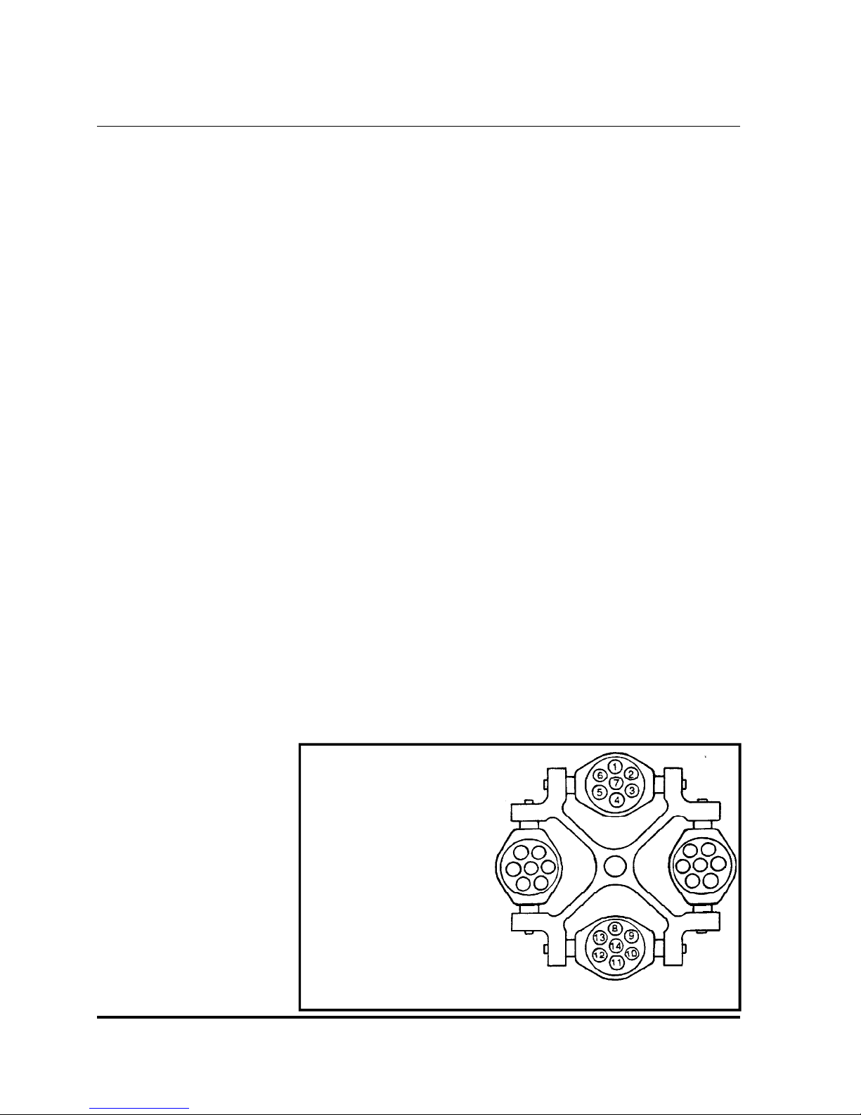
For example, load tubes in the
following manner:
1. Load four tubes.
Positions 3, 6, 10, 13
or 2,5,9,12
or 1,4,8,11
2. Load six tubes.
Positions 6,7,3,13,14,10
or 5,7,2,12,14,9
or 1,7,4,8,14,11
3. Load an odd number of tubes.
Not recommended (unless a
dummy tube is used for balance.)
Centra-CL2 Instruction Manual

4 APPLICATIONS
This section describes the use of specific rotors and accessories. More
detailed information is often shipped with the rotor or accessory itself. This
section contains four reference tables:
4.1 Speed And Force Table
4.2 Derating Table for Dense Samples
4.3 Chemical Resistance Table
4.4 Decontamination Table
4.5 Nomograph
Relative centrifugal force (RCF or G-force) at a given speed varies with the
rotor, and with the length of the sample tube, because the distance of the
tube’s tip from the center of rotation is different. The Speed and Force Table
indicates the maximum speed and RCF the Centra-CL2 can achieve with
various rotor/accessory combinations.
The Derating Table specifies reductions in rpm when spinning samples with
specific gravity above 1.2.
Misapplication of any tube can cause tube rupture. To avoid this, compare
the G forces specified in the Speed and Force Table with the ratings for the
tubes you are using. If the tubes are not rated for the force the centrifuge will
apply, reduce the speed to the G force limit of your tubes.
Your IEC centrifuge is made of materials designed to resist attack from most
laboratory chemicals. The interior of the rotor chamber is Painted steel.
Rotors and accessories placed in the chamber are made of a variety of
materials, including aluminum and polypropylene. The Chemical Resistance
Table shows the suitability of each material with different classes of reagents.
The Decontamination Table lists compatible methods of decontamination
which may be used on the IEC Centra-CL2 centrifuge.
The Nomograph provides an easy method of converting RPM to RCF (or xg).
Section 5.1 describes how to clean and remove corrosion from the chamber,
rotors, and accessories. Follow these instructions, and clean spills promptly,
to minimize the effects of corrosive chemicals, before any resulting chemical
attack requires more expensive repair. Replace metal locking nut, rotors, or
accessories if they become cracked, deformed, or gouged.
Centra-CL2 Instruction Manual 7

4.1 Speed And Force Tables
Rotor 215 4-Place Swinging Bucket Rotor
Tube Maximum Shield or
No. x Vol. (ml) Tube RPM / RCF Radius Tr Ring Carrier Adapter Cushion
8x50ml Falcon/Corning conical plastic 3100 1510 14.1 4x326 8x320 - 8x315
8x50ml Corning 8300-50 conical glass 3100 1510 14.1 4x326 8x320 - 571
8x15ml Falcon/Corning conical plastic 3100 1510 14.1 4x326 8x320 8x1106 570
4x50ml Falcon/Corning conical plastic 3350 1750 13.9 4x325 4x320 - 4x315
4x50ml Corning 8300-50 conical glass 3350 1750 13.9 4x325 4x320 - 571
4x15ml Falcon/Corning conical plastic 3350 1750 13.9 4x325 4x320 4x1106 570
4x50ml sealed Falcon/Corning conical plastic 3175 1750 15.4 4x350 4x323 315
4x15ml sealed Falcon/Corning conical plastic 3350 1750 13.9 4x325 4x320 4x1106 4x668
4x15ml sealed Falcon/Corning 3175 1710 15.2 4x350 4x7323 1106 4x571
4x10-15ml sealed Vacutainer 16x100-125mm 3175 1710 15.2 4x350 4x7323 1106 4x668
4x7ml sealed Vacutainer 13x100mm 3175 1710 15.2 4x350 4x7323 4x1105 4x571
12x10ml 16x100mm 3450 1725 12.9 4x366 4x10¹³ - 570
12x7ml 16x75mm 3450 1725 12.9 4x366 4x10¹³ - 570
16x7ml 13x100mm 3450 1700 12.8 4x366 4x10¹⁸ - 667
16x5ml 13x75mm 3450 1700 12.8 4x366 4x10¹⁸ - 667
20x5ml 12x75mm 4000 1975 11.1 4x366 4x369 - 567
20x3ml 10x75mm 4000 1975 11.1 4x366 4x369 - 567
Rotor 221 6-place Fixed Trunnion Swinging Bucket
Tube Maximum Shield or
No. x Vol. (ml) Tube RPM / RCF Radius Tr Ring Carrier Adapter Cushion
6x15ml Falcon/Corning 3100 1650 15.4 fixed 6x303 - 668
6x12.5ml Kimble 45170-125 3100 1650 15.4 fixed 6x303 - 668
6x12ml IEC 1629, 1649 3100 1570 14.6 fixed 6x303 - 570
6x10ml Corning 8080-10 3500 1890 13.8 fixed 6x356 - 668
6x10ml IEC 2046, 2067 3500 1780 13.0 fixed 6x356 - 570
Rotor 236 4-place Aerocarrier Horizontal Swing-Out Rotor
Tube Maximum Aero
No. x Vol. (ml) Tube RPM / RCF Radius Tr Ring carrier Adapter Cushion
4x50ml Falcon/Corning 3400 1950 15.0 fixed 4x2091S - -
8x15ml Falcon/Corning 3400 2000 15.5 fixed 4x2092S - -
8x10ml Kova/UriSystem 3400 2000 15.5 fixed 4x2092S - -
16x10ml Vacutainer 16x100mm 3700 2200 14.3 fixed 4x2093S - -
16x7ml Vacutainer 13x100mm 3700 2200 14.3 fixed 4x2093s - -
16x7ml Hemogard Vacutainer 13x100mm 3700 2200 14.3 fixed 4x2093s - -
28x7ml Vacutainer 16x75mm 3900 2150 12.7 fixed 4x2094S - -
28x5ml Vacutainer 13x75mm 3900 2150 12.7 fixed 4x2094s - -
28x5ml Hemogard Vacutainer 13x75mm 3900 2150 12.7 fixed 4x2094s - -
8
Centra-CL2 Instruction Manual

Rotor 801 6-Place 45 degree Fixed Angle Rotor
Tube Maximum
No. x Vol. (ml) Tube RPM / RCF Radius Shield Adapter Cushion
6x50ml Falcon/Corning conical plastic 3900 2050 12.1 6x305 - 6x315
6x50ml Corning 8300-50 conical glass 3900 2050 12.1 6x305 - 571
6x15ml Falcon/Corning conical plastic 3900 2050 12.1 6x305 6x1106 570
6x50ml Falcon/Corning conical plastic 4500 2450 10.8 6x320 - 6x315
6x50ml Corning 8300-50 conical glass 4500 2450 10.8 6x320 - 571
6x15ml Falcon/Corning conical plastic 4500 2450 10.8 6x320 6x1106 570
Rotor 804S 4-Place 40 degree Fixed Angle Rotor
Complete with 4 x 323 Sealed Buckets
Tube Maximum
No. x Vol. (ml) Tube RPM / RCF Radius Shield Adapter Cushion
4x50ml Falcon/Corning conical plastic 4200 2270 11.5 323 - 315
4x50ml Corning 8300-50 conical glass 4200 2270 11.5 323 - 571
4x15ml Falcon/Corning conical plastic 4200 2270 11.5 323 6x1106 570
4x60ml Corning 8540-60 2500 1000 14.3 4x341 - 572
Rotor 809 12-Place 45 degree Fixed Angle Rotor
Tube Maximum
No. x Vol. (ml) Tube RPM / RCF Radius Shield Adapter Cushion
12x15ml Falcon/Corning conical plastic 3800 2150 13.3 302 - 668
12x15ml Corning 8080-15 conical glass 3800 2050 12.7 302 - 570
126xDevice Amicon Filtration Device 3900 2050 13.4 302 - -
12x10ml Corning 8080-10 4500 2310 10.2 12x356 - 570
12xDevice Filtron or Millipore Devices 4500 2490 11.0 12x356 - -
12x10ml Corning 8080-10 4100 2270 12.1 12x303 - 12x668
12x10ml 17x102mm 4100 2120 11.3 12x303 - 570
Rotor 841 12-Place 45 degree Fixed Angle Rotor
Tube Maximum Use
No. x Vol. (ml) Tube RPM / RCF Radius Adapter
12x1.5-2.0ml microtubes 8500 4680 5.8 -
12x0.7ml microtubes 8500 4770 5.9 5763
12x0.5ml microtubes 8500 3960 4.9 5763
12x0.4ml microtubes 8500 4680 5.8 5764
12x0.25ml microtubes 8500 3630 4.5 5764
Centra-CL2 Instruction Manual 9

4.2 Derating Table for Dense Samples
The Speed and Force Table lists the Maximum speed for each rotor/
accessory combination in the Centra-CL2. IEC guarantees that the units can
achieve these speeds when used at nominal voltage.
These speeds are guaranteed only with samples whose specific gravity is not
greater than:
1.2 for swinging bucket rotors
1.5 for angle rotors
For denser samples, the maximum guaranteed speed is reduced (derated) by
a factor from the table below:
Derating Factor for:
Specific Gravity
1.2 1 1
1.3 .960 1
1.4 .925 1
1.5 .894 1
1.6 .866 .967
1.7 .839 .939
1.8 .816 .912
1.9 .794 .888
2.0 .774 .866
2.1 .755 .844
2.2 .738 .825
2.3 .721 .807
2.4 .707 .790
2.5 .692 .774
2.6 .678 .758
2.7 .666 .744
2.8 .654 .731
2.9 .642 .719
3.0 .632 .707
Example. An angle rotor rated for 5,000 rpm, used with samples with a
specific gravity of 1.6, should not be spun faster than (5,000 x .967 =) 4,835
rpm.
Swinging Bucket Fixed Angle
Specific gravities greater than 3.0. This table is based on the formula:
...where s
1.5, depending on the type of rotor), and s
sample in question. You can use the same formula to compute derating
factors for specific gravities greater than 3.0.
10
√(s
)
is the maximum specific gravity allowed before derating (1.2 or
0
0/sa
is the actual specific gravity of the
a
Centra-CL2 Instruction Manual
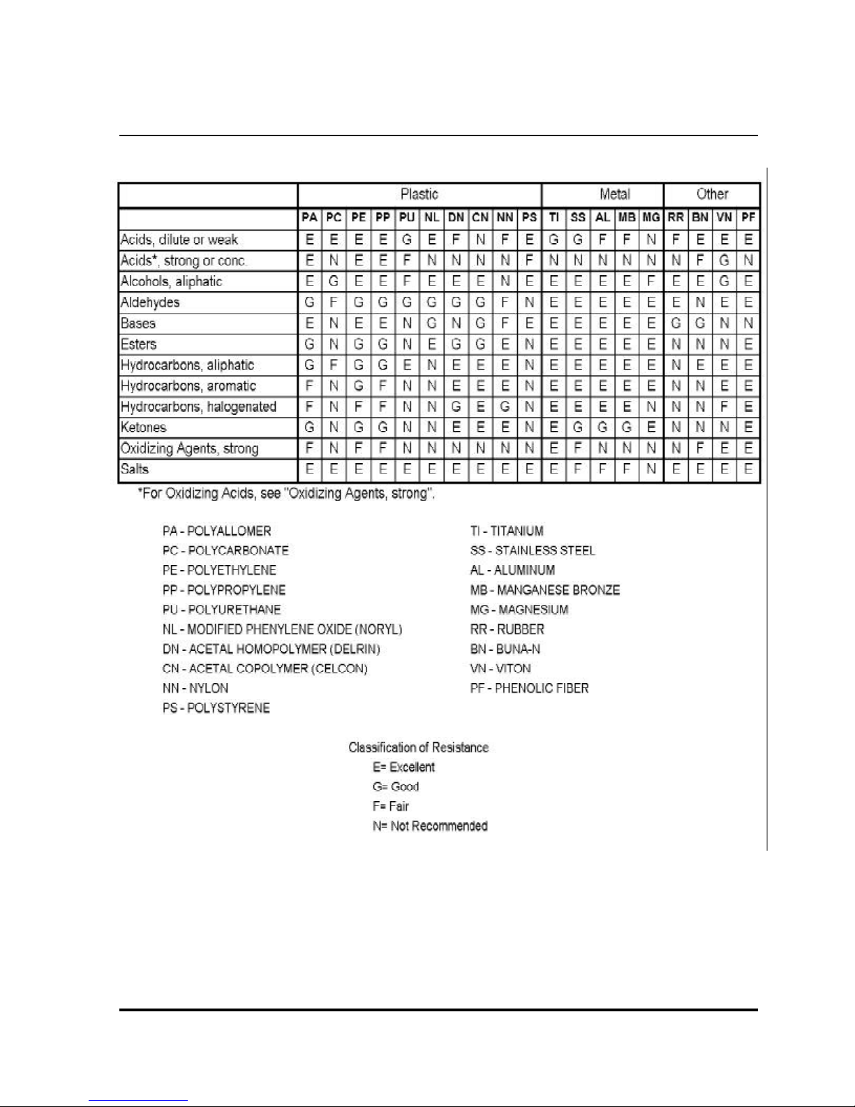
4.3 Chemical Resistance Table
Centra-CL2 Instruction Manual 11
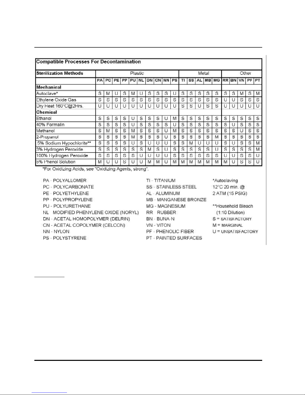
4.4 Compatible Processes For Decontamination
WARNING:
This chart describes the material compatibility of various sterilization methods. It does not specify
the adequacy of sterilization. Refer to section 4.3 Chemical Resistance Table for material
compatibility during centrifugation.
12
Centra-CL2 Instruction Manual
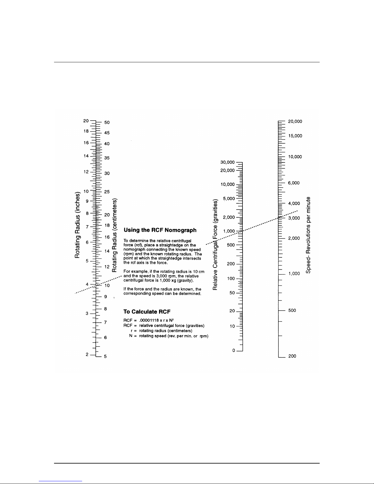
4.5 RCF Nomograph
Centra-MP4/MP4R Operation Manual 29
 Loading...