


95 Series
Operator’s Guide
Personal Portable Gas Monitor
HS-95, CO-95, OX- 95

PROPRIETARY STATEMENT
Thermo GasT ech owns proprietary rights in the information disclosed within. By
receiving this document, the recipient agrees that neither this document nor the
information disclosed within nor any part shall be reproduced or transferred to other
documents or used or disclosed to others for manufacturing or for any other purpose
except as specifically authorized in writing by Thermo GasTech.
COPYRIGHT STATEMENT
Information contained in this document is protected by copyright. No part of this
document may be photocopied, reproduced, or translated to another program or
system without prior written authorization from Thermo GasTech. , © 2001,
Thermo GasTech.
TRADEMARK STATEMENT
Protected through use and/or registration in the United States and many foreign
countries are the trademarks and service marks of Thermo Gas Tech. The use of the
® symbol indicates registration in the United States only; registrations may not
have been issued at present in other countries. All other product names and logos
are trademarks of their respective owners.
®
GASTECH
Patent and Trademark Office.
is a trademark of Thermo GasTech and is registered with the U.S.
DISCLAIMER
Under no circumstances will Thermo GasTech be liable for any claims, losses, or
damages resulting from or arising out of the repair or modification of the equipment
by a party other than Thermo GasTech or its authorized service representatives, or
by operation or use of the equipment other than in accordance with the printed
instructions provided by Thermo GasTech or if the equipment has been improperly
maintained or subject to neglect or accident. Any of the foregoing will void the
warranty.
EXPORT STATEMENT
Export of the information and products in this manual from the U.S.A., or re-export
from another country, may require written authorization from the U.S. Department
of Commerce. Prin ted in th e U.S.A .
REVISIONS TO MANUAL
All information contained in this manual is believed to be true and correct at the
time of printing. However, as part of its continuing efforts to improve its products
and their documentation, Thermo GasTech reserves the right to make changes at
any time without notice. Any revised copies of this manual can be obtained by
writing Thermo GasTech.
ii 71-0011 — REV E

WARNING
T
HIS INSTRUMENT IS DESIGNED TO DETECT
ONE
FLAMMABLE VAPORS, OXYGEN CONTENT, AND/OR TOXIC
GAS
HARMFUL
WILL
ESSENTIAL
PARTICUL ARLY THOSE CONCERNING START UP
OPERATION, CALIBRATI ON, AND MAINTEN ANCE, BE
READ
AND TO GIVE WARNING BEFORE THEY REACH
CONDITIONS. IN ORDER TO ENSURE THAT IT
WARN OF DANGEROUS CONCENTRATIONS, IT IS
,
UNDERSTOOD, AND FOLLOWED
OR MORE OF THE FOLLOWING
THAT THE INSTRUCTIONS IN THIS MANUAL
:
.
,
,
NOTATION CONVENTIONS
Notices are used in this operator’s guide to alert you to hazardous
conditions to person or instru ment and to n otify you of a dditional
informat ion. This operator’s guide use s the following notices:
WARNING
Notifies you of potential da ng er of persona l injury .
CAUTION
Notifies you of potential da m age to equi pm e nt.
NOTE
Notifies you of additional or critical information.
71-0011— REV E iii

SERVICE POLICY
Thermo GasTech maintains an instrument service facility at the
factory as well as authorized service facilities around the world.
Should your instrument require service, you may contact us toll free
at 1-877-GASTECH (427-8324) for US only or 1-510-745-8700,
or visit our website www.thermogastech.com for authorized service
locations.
For warranty or non-warranty repairs, call us to complete a Return
Material Authoriz atio n (RMA) fo rm, obtai n bi llin g and shippin g
information and tell us the nature of the problem. For non-warranty
repairs, you will n eed to pro vide a purchase ord er numb er. If you
need to set a limit to the repairs costs, state a “Not to Exceed” figure.
If you need a quotation before you can authorized the repair costs,
so state, but understand this will incur additional costs and may
delay processing of the rep air.
You may send the unit, prepaid, to: Thermo GasTech, 8407 Central
Ave., Newar k, C A 94 56 0-3431 , Attn.: Service Department.
Enclose the copy of the RMA (Return Material Authorization) that
was previously faxed to you. Pack the instrument and all its
accessories (preferab ly in its original packing) and any special
instructions.
Repairs are warranted for 90 days from the date of shipment.
Sensors have individual warranties.
NOTE
Thermo GasTech assumes no liability for wo rk pe rform ed by
unauthorized service facilities.
iv 71-0011 — REV E

WARRANTY STATEMENT
Thermo GasTech (the “Company”) warrants that the Products will
operate substant ia lly in conformance with the Company’s published
specificatio ns, when subjected to norm al , prope r, and intended usage by
properly trained pe r sonnel, for a period of one (1) year afte r shipment to
Customer (the “Warranty Period”). The Compan y agre es during the Warranty
Period, provided it is promptly notified in writing upon the disc ove r y of any
defect and further provided that all costs of returning the defective Products to
the Company are prepaid by Customer, to repair or replace, at the Company’s
option, defective products so as to cause the same to oper a te in substantial
conformance with said specifications. Re placement parts may be ne w or
refurbished, at the election of the Company. All replaced parts shall become
the property of the Company.
Lamps, pump diaphragms/valves, batteries, fuses, bulbs, and other expendable
items are expressly excluded from the warranty.
The Company’s sole liability with respe c t to e quipment, ma te r ials, parts, or
software furnished to the Company by third party suppliers shall be limited to
the assignment by the Company to Customer of any such third-party
supplier’s warranty, to the extent the same is assignable. In no event shall the
Company have an y obligation to make repa ir s, replacements, or corre c tions
required, in whole or in part, as the result of (i) normal wear and tear, (ii)
accident, disaster, or event of force majeure, (iii) misuse, fault, or negligence
of or by Customer, (iv) use of the Products in a ma nne r for whic h the y we r e
not designed, (v) causes external to the Products such as, but not limited to,
power failure or electrical power surges, or (vi) use of the Pr oduc ts in
combination with equipment or soft ware not supplied by the Com pa ny.
ANY INSTALLATION, MAINTENANCE, REPAIR, SERVICE,
RELOCATION, OR ALTERATION TO OR OF, OR OTHER TAMPERING
WITH, THE PRODUCTS PERFORMED BY ANY PERSON OR ENTITY
OTHER THAN THE COMPANY WITHOUT THE COMP ANY’S PRIOR
WRITTEN APPROVAL, OR ANY USE OF REPLACEMENT PARTS NOT
SUPPLIED BY THE COMPANY, SHALL IMMEDIATELY VOID AND
CANCEL ALL WARRANTIES WITH RESPECT TO THE AFFECTED
PRODUCTS.
THE OBLIGATION TO REPAIR OR REPLACE A DEFECTIVE
PRODUCT SHALL BE THE SOLE REMEDY OF CUSTOMER IN THE
EVENT OF A DEFECTIVE PRODUCT. EXCEPT AS EXPRESSLY
PROVIDED IN THIS SECTION, THE COMPANY DISCLAIMS ALL
WARRANTIES, WHETHER EXPRESS OR IMPLIED, ORAL OR
WRITTEN, WITH RESPECT TO THE PRODUCTS, INCLUDING
WITHOUT LIMITATION ALL IMPLIED WARRANTIES OF
MERCHANTABILITY OR FITNESS FOR ANY PARTICULAR
PURPOSE. THE COMPANY DOES NOT WARRANT THAT THE
PRODUCTS ARE ERROR-FREE OR WILL ACCOMPLISH ANY
PARTICULAR RESULT.
71-0011— REV E v

vi 71-0011 — REV E

TABLE OF CONTENTS
Chapter 1 INTRODUCTION.............................................1-1
OVERVIEW ............................................................1-1
DESCRIPTION........................................................1-1
SPECIFICATIONS..................................................1-2
Chapter 2 PHYSICAL DESCRIPTION...........................2-1
OVERVIEW ............................................................2-1
PHYSICAL DESCRIPTION................ ...................2-1
Electronics Assembly................ .................... .....2-3
Buzzer................ ............................................... ..2-4
Housing/Housing Gasket....................................2-4
Sensor .................................................................2-5
Battery Compartment..........................................2-5
Chapter 3 START UP & OPERATION ...........................3-1
OVERVIEW ............................................................3-1
START UP................. .............................. ................3-2
INSTRUMENT OPERATION................................3-3
Alarm Indications...............................................3-3
Low or Dead Battery Indications........................3-4
Weak or Failed Sensor Indications.....................3-5
INTERFERENCE CHARTS...................................3-6
OPTIONAL ACCESSORIES..................................3-8
Hand-aspira ted Samp le -dr aw Ada pt er..... ...........3-8
Earphone............... ...................................... ........3-9
Vibrating Alarm ..................................................3-9
71-0011 — REV E vii

Chapter 4 CALIBRATION & MAINTENANCE............ 4-1
OVERVIEW ....................................................... .....4-1
TEST KIT ................................................................4-2
Test Gas Cylinders......... ............................. ........4-2
H2S Regulato r (for HS-95). ... ... ... ... ... ... ..... ... ... ... 4-2
Dispensing Val ve (for CO-95 and OX-95)... ... ... 4- 2
Flowmeter (f or CO-9 5 and OX-95)........... ... ... ... 4- 3
Test Cup......................... ............................. ........4-3
Tubing.............. ........... ...................................... ..4-3
Test Kit Instruction Sheet...................................4-3
CALIBRATION PROCEDURES............................4-3
Preparing for Calibration ( all m odels).......... ... ... 4-4
How to Use the Control Buttons.........................4-4
Calibration (HS-95, CO-95) ............................... 4-6
Calibratio n (OX-95) .......... ............................. .....4-7
If Calibration Fails ..............................................4-8
Switch to Default Zero (OX-95).........................4-9
Return to Normal Operation.............................4-10
MAINTENANCE ..................................................4-11
How to Open and Close Your Monitor.............4-11
Troubleshooting Guide.....................................4-12
Changing Alarm Setpoints................................4-13
Changing the Alarm Delay...............................4-14
Replacing Defective Components....................4-14
FRUs AND ACCESSORIES LIST........................4-19
viii 71-0011 — REV E

INTRODUCTION
OVERVIEW
This Operator’s Guide provides information on the proper
set-up, use, calibration, and maintenance of the 95 Series of
single-gas monitoring instruments.
Chapter 2 contains a physi c al description of yo ur monitor.
Instructions to use and interpret monitor readings are in
Chapter 3, Start Up and Operation. Chapter 4, Calibrat ion
and Maintenance, also contains troubleshooting information
and a list of replacement part numb ers.
CHAPTER 1
DESCRIPTION
The 95 Series is a li ne of three personal, portable gas
monitors that eac h detect one gas. Each pocket-size
instrument detect s either oxygen (O2), hydrogen sulfide
S), or carbon monoxide (CO), and actuates an alarm to
(H
2
alert you sho uld th e m easu re d g as surp ass t he ala rm settin g.
Table 1-1 lists specificatio ns for each model.
71-0011 — REV E 1-1

95 Series Operators Guide
SPECIFICATIONS
Table 1-1 95 Series Gas Monitor Specific a tio ns
Model Designat ion
(Gases D etected)
OX-95 (0-30.0% O2 in 0.1% increments)
HS-95 (0-100 ppm H
S in 1 ppm increments)
2
CO-95 (0-500 ppm CO in 1 ppm increments)
Detection Method Diffusion, electrochemical
Response Time
Accuracy
Repeatability
90% in 30 seconds
±5% of reading (±0.2% O
±3% of reading (±012% O
for OX-95**)
2
for OX-95**)
2
Gas Alarm Setpoints OX-95: 19.5% vol, decreasing, (programmable)
23.5% vol, increasing, (pro grammable)
HS-95: 10 ppm, and 15 ppm, (programmable)
CO-95: 25 pp m, 200 ppm, (progr am mable)
Gas Alarm Delay 3 sec. (programmable to 0, 1, 2, or 3 sec.)
Other Alarm Modes Weak or failed sensor, low or dead battery
Operator Controls - Power
- ZERO/-
switch
button
- SPAN/+ button
Dimensions
Weight
Battery Life
(approxim ate)
4.5 in. H x 2.5 in.W x 1.0 in. D
6.5 ounces
Continuous, non-alarm operation per one 9V
alkaline ba ttery:
OX-95: 3,200 hours
CO-95 and HS-95: 2,500 hours
Standard* a nd
Optional Accessories
Operating Temper ature and Humidity
Regulatory
Approvals
Operator’s guide*, hand-aspirated sample-draw
adapter, earphone, test kits, vibrating alarm,
*strap.
-4º F (-20º C) to 113º F (45º C)
0-95% relative humidity (RH), non-condensing
UL classified; CSA classified
Class I, Division 1, Groups A, B, C, and D
DEMKO EEx ia IIB T2
** In range of ±2% O2 from calibration point.
Specifications are subject to change without notice.
1-2 71-0011 — REV E

PHYSICAL
DESCRIPTION
CHAPTER 2
OVERVIEW
This chapter describes the physical components of your
95 Series gas monitor. For purposes of identification throughout
this guide, the monitor is describ ed as having front and rear
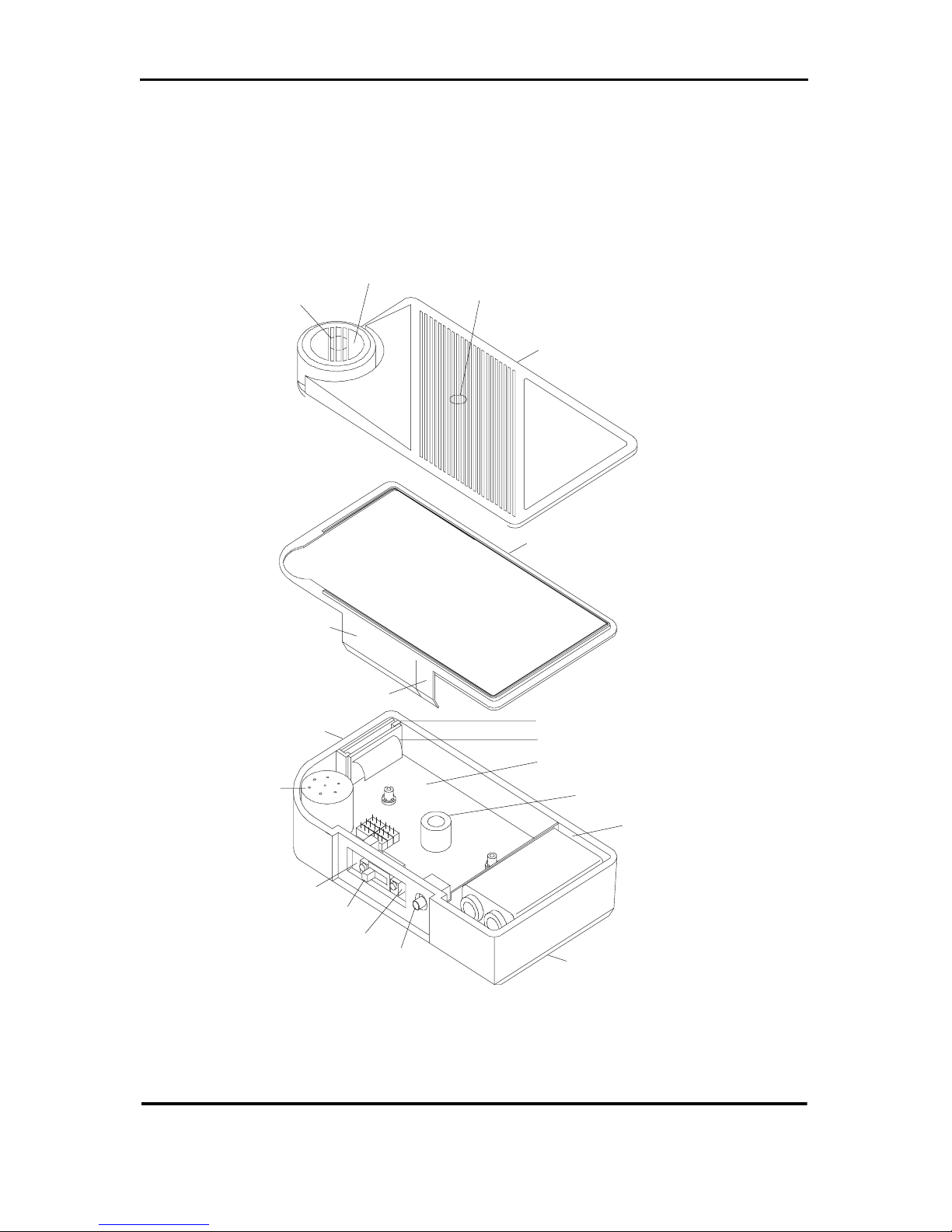
housing hal ves, as shown in Figure 2-1.
PHYSICAL DESCRIPTION
To open your mo nitor, loosen the two captive screws on the rear
cover, then separate the two halves.
The components identified in Figure 2-1 are described in this
chapter. The field replacea ble units (FRUs) include the housing
gasket, sensor, and battery.
71-0011 — REV E 2-1
95 Series Operator’s Guide
(Hydrophobic
membrane
behind grille)
Sens or P o r t
Buzzer Port
FRONT HOUSING
Operator Controls C over
Earphone Jac k Cover
LCD
Plug-in
Sensor
Zero Button
Power Switch
Span Button
Earphone Jack
HOUSING GASKET
ELECTRONICS ASSEMB L Y:
Display Board
Display Cable
Main Board
Buzzer
Battery
Compartment
REAR HOUSING
Figure 2-1 Components of the 95 Series Gas Monitor
2-2 71-0011 — REV E

Physical Description
Electronics Assembly
The electronics assembly consi sts of the main board, operator
controls (power switch, buttons, and earphone jack), display
board with li qu id cr ystal d isplay (LCD), and t he display cable. If
any of these components fail , contact the factory for repair.
Main Board
All buttons and operator co ntrols are part of the main board.
Control circuitry for other components is also located on the
main boa rd.
ZERO/- and SPAN/+ Buttons
The ZERO/- button alone is used to zero the sensor and decrease
parameter settings. The SPAN/+ button alone is used to set
sensor span and increase parameter settings.
The ZERO/- and SPAN/+ buttons are pressed together to select
setting modes.
Power Switch
Set to the left position (toward the sensor) to turn the instrument
on. Set to the right position (away from the sensor) to turn the
instrument off.
Earphone/Vibrating Alarm Jack
The earphone or vibrating alarm accessory is connected to th is
jack.
71-0011 — REV E 2-3

95 Series Operator’s Guide
Display Board/Display Cable
The display board is attached to th e main board by a
nondetachable ribb on cable.
Liquid Crystal Display (LCD)
The LCD panel is visible through the window in the top of the
housing. A red LED is visi ble through the displa y panel as a
visual indication of alarm cond itions. Display readings are
described in Chapter 3.
Buzzer
The buzzer is mounted on the main board.
Housing/Housing Gasket
The instrument housing is a two- piece plastic c a se held together
by two captive screws. A mylar gasket covers the operator
controls to keep water and dust away from the internal
components. The case is sealed using a detachable rubber gasket
and two flaps to protect the operator controls and earphone/
vibrating alarm jac k.
The letters Z, P, and S on the inside of the flap identify the
position of the ZER O/- b utton, the po wer switch, and the SPAN/+
button, respectively. The arrow next to the P indicates the
direction to m o ve the power switch to t urn th e i nstrum ent o n an d
off.
2-4 71-0011 — REV E

Physical Description
Sensor
Each model has a dedicated, detachable sensor that plugs into the
main boa rd. A hyd rophobi c (wat erproof ) membra ne on the insi de
of the case sensor opening i s held down by a gasket. The
membrane permits diffusion of the surrounding atmosphere to
the sensor.
When sufficiently exposed to the target gas, the electrical output
of the sensor ca uses a readin g on the displa y. Readings are in
parts per million (PPM) for H
volume for O
.
2
S and CO, or percent ( %) by
2
Battery Compartment
The battery com part ment houses a standard 9V alkaline battery.
71-0011 — REV E 2-5

95 Series Operator’s Guide
2-6 71-0011 — REV E

START UP &
OPERATION
CHAPTER 3
OVERVIEW
This chapter describes the normal operation of your 95 Series gas
monitor, and how to respond to abnormal operat ion. Normal
operation is any time that start up has been completed, and the
monitor is not indi cating an alarm, fa ult, or low batte ry condition.
This chapter also contains interference charts listing other gases
that can affect the sensor in the HS-95 or CO-95 monitor, and
procedures to use the optional accessories available for your
monitor.
71-0011 — REV E 3-1

95 Series Operator’s Guide
START UP
Perform the following steps to start up your monitor. Refer to
Figure 2-1 as needed.
CAUTION
Perform start up only in a fresh air environment.
1. Flip open th e housing gasket flap that covers the operator
controls, and move the power switch toward the sensor to
turn the monitor on. The unit should sound a single audible
tone, and display the installed ve rsion of software. A
number will then be displayed. Allow a few seconds for the
reading to stabilize, then check the display. If your HS-95 or
CO-95 shows a readin g of 0 PPM, or your OX-95 a reading
of 20.9%, proceed to Step 4. If the reading is anything other
than this, perform Step 2 or 3, as appropriate.
2. Zero the HS-95 or CO-95 by pressing the ZERO/- button
until the PASS message app ears (about 5 seconds).
3. Span the OX-95 by pressing the SPAN/+button until the
PASS message appears (about 5 seconds).
4. Close the operator controls flap. Your monitor is ready for
use.
3-2 71-0011 — REV E

Start Up & Operation
INSTRUMENT OPERATION
In normal operation, your instrument monitors the environment
and displays the current gas concentration. The instrument
displays alarms to indicate gas concentrations outside preset
limits. Low and dead battery as well as weak and failed sensor
conditions are also indicated.
NOTE
Momentary small negative gas readings are not abnormal with
the HS-95 and the CO-95. The instrument automatically corrects
itself.
Alarm Indications
When a ga s conc ent rati on re aches the alar m set poin t, th e al arm is
indicated by the buzzer pulsing, the red alarm light flashing, and
the gas reading blinking, all in unison. For the HS-95 and the
CO-95, the gas alarm is a pulsing audible tone with a blinking
reading for the low level alarm, and a steady audibl e tone with
pulsin g display for the high level alarm. For the OX-95, you can
tell whether the alarm is a high or low alarm b y the ga s reading .
A high O
signified by a pulsi ng audibl e tone. A low O
reading below the low setpoint, and is signified by a steady
audible tone.
alarm shows a reading above the high setpoint, and is
2
alarm shows a
2
NOTE
Pres et alarm setpoints conform to current OSHA standards, but
can be adjuste d. See Chapter 4 for alarm adjust procedures.
71-0011 — REV E 3-3

95 Series Operator’s Guide
Recommended Action:
When an alarm occurs, follow the established procedure for an
alarm condition. If no procedu r e is in place, please establish one
that is appropriate for your application.
The alarm circuit is self-resetting. When the instrument is moved
from the suspect environment, the al arm ceases, and the
instrument r eturns to normal operat ion. However, this does not
mean that the danger has passed.
Low or Dead Battery Indications
Low Battery: When your monitor senses that t he battery has
approximate ly 8 hours rem aining, th e word L OB AT blinks on the
LCD. In addition, the buzzer emits a short chirp and the red
alarm light flashes every 30 seconds.
Dead Battery: When the battery is past the point of useful
operation, LOBAT appears steadily on the LCD. In addition, the
buzzer sounds continuously and the red alarm light is on steady.
When these indications occur, the instrument is not operable.
Recommended Action:
Replace a dead ba ttery immediatel y or a low battery as soon as
possible, foll owing the procedure in Chapter 4 .
3-4 71-0011 — REV E

Start Up & Operation
Weak or Failed Sensor Indications
Weak sensor: When a weak sensor is detected during
calibration, the word FAULT blinks on the LCD. The instrument
is still functioning normally , b ut you should replace the sensor as
soon as possible.
Failed sensor : When a defective sensor or sensor circuit is
detected, the word FAULT is displayed on the LCD. In addition,
the buzzer sounds continuously and the red alarm light is on
steady. A fault condition is caused by a missing or bad sensor, a
bad connection, or a main board sensor circuit fault.
Recommended Action:
Remove the instrument from the monitoring environment. Refer
to the troubleshooting guide in Chapter 4 to determine the cause
of the alarm conditio n and the recommended course of action.
WARNING
A reading of 23.5% O2 or more must be treated as a hi ghoxygen alar m condit ion unti l pr oven ot h e r w is e.
71-0011 — REV E 3-5

95 Series Operator’s Guide
INTERFERENCE CHARTS
Your HS-95 or C O -95 monitor can respond to gases other than
S and CO. Tables 3-1 and 3-2 ind icate the readings that can
H
2
occur for specified concentrations of other gases.
Table 3-1 HS-95 Interference Chart, H2S Sensor
Interfering Gas Concentration Tested Reading
Acetylene
C
2H2
Chlorine
Cl
2
Dimethyl sulfide
3)2
6H14
2
4
OH
3
SH
3
2
2
S
(CH
Hexane
C
Hydrogen
H
Methane
CH
Methanol
CH
Methyl me rc a ptan
CH
Nitrogen dioxide
NO
Sulfur dioxide
SO
50 ppm 170 ppm
5 ppm Negative response
(AVOID)
2.8 ppm No response
4400 ppm No response
10,000 ppm 8 ppm
2.5% No response
1000 ppm No response
5 ppm 6 ppm
10 ppm 1 ppm
10 ppm 1 ppm
3-6 71-0011 — REV E

Start Up & Operation
Table 3-2 CO-95 Interference Chart, CO Sensor
Interfering Gas Concentration Tested Reading
Acetylene
C
2H2
Chlorine
Cl
2
Hexane
C
6H14
Hydrogen
H
2
Hydrogen sulfide
S
H
2
Methane
CH
4
Methanol
OH
CH
3
Methyl me rc a ptan
SH
CH
3
Nitrogen dioxide
NO
2
Sulfur dioxide
SO
2
100 ppm No response
7 ppm No response
4400 ppm No response
100 ppm 12 ppm
10 ppm No response*
2.5% No response
1000 ppm No response*
5 ppm No response*
10 ppm No response*
10 ppm No response*
* The CO sensor has an internal filter that absorbs certain gases
to keep them from interfering with the CO reading. The internal
filter is good for appro ximately on e year. If the filter is saturated,
the gases marked with an asterisk (*) may produce an
interference reading.
71-0011 — REV E 3-7

95 Series Operator’s Guide
OPTIONAL AC CESSORIES
This section de scrib es the o pt ion a l acce ssori es av a ilable for your
95 Series gas monitor, and how to use them.
Hand-aspirated Sample-draw Adapter
Description
The sample-draw adapter is used to draw a gas sample from a
particular location. The adapter consists of a test cup, aspirator
bulb, 10 feet of tubing, fittings, and a probe.
How to Use
1. Attach the test cup o v er the sen sor po rt. The c up f its into t he
groove around the port, and is held snugly by the retainer
arm pressing onto the back of the instrument.
2. Place the probe in the sampling location.
3. Squeeze the aspirator bulb repeatedly until the display
stabilizes. Continue to squeeze the bulb repeatedly during
the monitoring process, to maintain the sample flow to the
monitor.
4. After use, the adapter can remain connected for the next use.
Ke ep in min d that the mo nitor is not operationa l in the
diffusion mode if the adapter is in place.
3-8 71-0011 — REV E

Start Up & Operation
Earphone
Description
The earphone has an ea rpiece on one end, w ith a cord and
adapte r plu g e xtendin g fr o m it. The ea rphone rep e ats the a ud ible
alarms of your monit or. Since the earph one is in your ear during
operation, y ou can hear the alarm in noisy environments.
How to Use
1. Open the earphone flap, then insert the adapter plug into the
earphone jack.
2. Insert the earpiece into your ear.
Vibrating Alarm
Description
The Vibrating Alarm is housed in its own compact case with a
cord and adapter that plug into the 95 Series earphone/vibrating
alarm jack. It operates from its own batteries and vibrates
simultaneously with t he ala rms of the mon itor. It has its ow n clip
that can be attached to the belt or shirt pocket.
How to Use
1. Plug the Vibrating Alarm into the instrument.
2. Place the plastic housing on your belt or po cket, (the belt is
recommended for maximum effectiveness).
3. Turn the instrument on.
4. Vibration should occur for approximatel y 1 second.
71-0011 — REV E 3-9

95 Series Operator’s Guide
Note: V ibration should always occur with the audible buzzer and
display l ight. If it does not vib rate, replace the batt ery. (see
chapter 4 for maintenance).
NOTE
Close the earphone flap when the earphone or vibrating alarm is
not in use.
3-10 71-0011 — REV E

CALIBRATION &
MAINTENANCE
CHAPTER 4
OVERVIEW
This chapter contains calibration instructions for all models of
the 95 Series single - g as monito rs.
A troubleshooting guide, alarm setting procedures, and field
replaceable unit (FRU) replacement procedures are also provided
in this chapter. A part number list for FRUs and accessories is on
the final page.
CAUTION
Calibrate or perform maintenance on you r instrument only in a
“fresh air” environment. For the HS-95, this is an environment
free of H
the OX-95, this i s an environment kno wn to consis t o f normal O
content.
71-0011 — REV E 4-1
S. For the CO-95, this is an environment free of CO. For
2
2

95 Series Operator’s Guide
TEST KIT
The test kits includes test ga s cylin ders, a re gulator or di spensing
valve and flowmeter, a test cup, and flexibl e tubing. The test kit
is hous e d i n a custo m storag e case.
Test Gas Cylinders
The test gas cylinder for the CO-95 contains 200 ppm of CO in
air. The test gas cylinder for the HS-95 co ntains 25 ppm of H
in N
is listed on the cylind er label. Th e cylinde r for zeroing th e O X-95
contains pure nit rogen (N2). The gas is released when the
regulator or dispensing valve is attached to the cylinder and the
flow control knob is opened.
. These concentrations are nominal; the actual concentration
2
S
2
H2S Regulator (for HS-95)
The H2S regulator allows the test gas to flow to the HS-95 at a
fix ed flow rate. T he regulator gauge sho ws the pressure of the gas
in the cylinder. The flow control knob opens and closes the
regulator. To connect, screw the regulator onto the c ylin de r, and
install the tubing leading to the test cup .
Dispensing Valve (for CO-95 and OX-95)
The dispensi ng va lve con trols the flo w of test gas to th e CO-95 or
the OX-95. The flow control knob opens and closes the valve and
controls the flow rate of the test sample. To connect, screw the
val ve on to the test c ylind er. Insert the gas outlet into the sample
tubing.
4-2 71-0011 — REV E

Calibration & Maintenance
Flowmeter (for CO-95 and OX-95)
The ball in the flowmeter column indicates the flow rate of the
gas from 0.2 to 2.0 standard cubic feet per hour (SCFH). The
inlet is on the bottom and the outlet is on the top.
Test Cup
The test cup is a rubber cylinder that fits into the groove around
the sensor port and is held in place by a retainer arm. A metal
fitting connects to the tubing.
Tubing
The 3/16 in. I.D flexible vinyl tubing connects the cylinder, the
flowmeter (CO-95 and OX-95) , and the test cup.
Test Kit Instruction Sheet
The test kit instruction sheet describes how to prepare and
operate the test kit with the 95 Series gas monitors.
CALIBRATION PROCEDURES
Calibration procedures include preparing your instrument,
verifying or adjusting zero, verifying or adjusting span, then
returning your instrument to normal operation.
WARNING
Accurate calibration is essential for correct gas or oxygen
readings. Incorrect calibration can impair the performance of
the instrument, placing you in potential danger if hazardous
conditions exist.
71-0011 — REV E 4-3

95 Series Operator’s Guide
Preparing for Calibration (all models)
NOTE
With a HS-95 or CO-95 , i f th e battery has gone de ad or the
battery has been out of the instrument for 30 minutes or more,
allow 1 hour afte r the new battery ha s bee n installed fo r the
sensor to stabil i ze before beginning calibration procedures.
1. Check that th e flow co ntrol kn ob or dis pensin g v al ve is shut
off. Sc re w the re g ulator or t he dispensin g v alv e onto th e test
cylinder for your de tector.
2. Securely attach one end of the tubing to the gas outlet of the
regulator or dispensing valve. For the HS-95, securely
attach the other end of the tubing directly to the test cup.
3. For the CO-95 or OX-95, attach the other end of the tubing
from the dispensin g valv e to th e i nlet (b ot tom ) c onnec to r of
the flowmeter. Attach a second piece of tubing between the
outlet (upper) connector of the flowmeter and the test cup.
CAUTION
The flowmeter must be vertical and right side up in order for you
to atta in accurate readings.
How to Use the Control Buttons
• The control buttons are ZERO/- and SPAN/+.
• A button should be pressed for at least 1/2 second to be sure
that it is recognized.
• The ZERO/- button is used to set zero. The SPAN/+ button
is used to set span. See the Calibration section for details.
4-4 71-0011 — REV E

Calibration & Maintenance
• When you press and release the ZERO/- and SPAN/+
buttons at the same time, the mode changes. In the HS-95
and CO-95, the modes are: span calibration (C), set low gas
alarm (L), set high gas alarm (H), set alarm delay (d), and
normal. In the OX-95, the modes are: set low alarm (L), set
high alarm (H), set alarm delay (d), and normal.
• When any setting mode is active, the mode letter is
displayed to the left of the setting: (C) for setting the span
calibration, (L) for setting the low and (H) for setting the
high alarm, and (d) for setting the alarm delay.
• Normal mode is not indicated by a letter. The space to the
left of the current gas reading is bl ank.
• In all setting mo des, press and release ZERO/- to decrease
and SPAN/+ to increase the setting by one count. Press for
at least 1/2 second before releasing. Hold the button do wn to
change the setting rapidly.
71-0011 — REV E 4-5

95 Series Operator’s Guide
Calibration (HS-95, CO-95)
Open the operator contr ols flap , and slide the power switch on
(toward the sensor). Allow a few seconds for the instrument to
stabilize.
1. Make sure the instrument is in a fresh air environment, free
of H
S or CO gas. Press and hold the ZERO/- b utto n. A lo w
2
bar is displayed to the left of the gas reading during the
automatic zero calibration. Release the button when the
PASS or FAIL message is displayed . The in strument returns
to normal mode, with the alarm inhibited for 2 minutes.
2. Go to span calibration mode by pressing and re leasing t he
ZERO/- and SPAN/+ buttons at the same time. The letter C
appears. The value display ed is the current span cal ibration
setting. If necessary, press the ZERO/- or SPAN/+ button to
change the setting to match the concentration indicated on
the test gas cylinder.
3. When the values match, return to normal mode by pressing
and releasing ZERO/- and SPAN/+ twice. The instrument
passes thro ugh set gas alarm (L & H) mo des and set delay
(d) mode and enters normal mode.
4. Fit the t e st cup into the groove around the sensor po rt with
the retainer arm around the back of the instrument holding
the cup in place. The fitting should extend to the right across
the top of the instrument.
5. Open the flow control knob on the H
the CO cyl inder dispensing va lve. F o r the HS-95, v erify that
the regulator gauge shows a pressure greater than 0. For a
CO-95, set the flow rate to 1.0 SCFH. Allow 90 seconds for
the reading to stabilize.
4-6 71-0011 — REV E
S cylinder re gulator o r
2

Calibration & Maintenance
6. Press and hold the SPAN/+ button. A high bar is displayed
to the left of the gas reading during the automatic span
calibration. Release the button when the PASS or FAIL
message is displayed. The instrument returns to normal
mode, with the alarm inhibited for 3 0 seconds.
NOTE
The HS-95 and CO-95 gas alarm is inhibited for 2 minutes after a
successful (PASS) zero calibration and after an unsuc ce ssfu l
(FAIL) span cal ib ration. The alarm is also inhibited for
30 seconds after a successful (PASS) span calibration. The alarm
is inhibit ed to allow you to finish cal i b rat ion witho ut s etting off
the alarm. Durin g the inhibit peri od, a rotating pa tt ern of
horizontal bars appears to the left of the gas reading to remind
you that t he alarm is shut off.
Calibration (OX-95)
Open the operator contr ols flap , and slide the power switch on
(toward the sensor). Allow a few seconds for the instrument to
stabilize.
1. Fit the t e st cup into the groove around the sensor po rt with
the retainer arm around the back of the instrument holding
the cup in place. The gas inlet should extend to the right
across the top of the instrument.
2. Open the N
1.0 SCFH. Allow 90 seconds for the reading to stab ilize.
cylinder dispensing valve. Set the flow rate to
2
The low oxygen alarm will sound. This is normal.
71-0011 — REV E 4-7

95 Series Operator’s Guide
3. Press and hold the ZERO/- b utton . A low b ar is display ed to
the left of the gas reading during the automatic zero
calibration. Release the button when the PASS or FAIL
message is displayed. The instrument retur ns to normal
mode, with the alarm inhibited for 2 minutes.
4. Turn off the gas and remove the test cup.
5. Let the instrument stabilize for 90 seconds in fresh air . Pres s
and hold the SPAN/+ button. A high bar is displayed to the
left of the gas reading du ring the automatic span calibration.
Release the button when the PASS or FAIL message is
displayed. The instru m ent return s to norm al mode, with no
additional alarm inhibition.
NOTE
The OX-95 gas alarms are inhibited for 2 minutes after a
successful (PASS) zero calibration and after an unsuc ce ssfu l
(FAIL) span cal ibration. This all ows y ou to finish calibration
without setting off an alarm. During the inhibit period, a rotating
pattern of horizontal bars appears to the left of the gas reading to
remind you that the alarms are shut off. The OX-95 alarms are
NOT inhibited after a successful (PASS) span calibration.
If Calibration Fails
On all models, if the zero or span calibration fails, the FAIL
message is displayed. Try the zero or span procedure a second
time. If the FAIL message appears again:
1. Turn the instrument off.
2. Replace the sensor.
4-8 71-0011 — REV E

Calibration & Maintenance
3. For the HS-95 or CO-95, all ow the new sensor to stabilize
for 1 hour. For the OX-95, allow the new sensor to stabilize
for 5 minutes.
4. Turn the instrument on.
5. Run the zer o and span calibrati on procedures from the
beginning.
WARNING
You should not ignore the al arm even if you de ci de that it was
caused by this mistake. Move immed ia tely to a safe area.
Switch to Default Zero (OX-95)
If you press and hold the ZERO/- button on the OX-95 while the
instrument is in fresh air, the sensor becomes uncalibrated, the
reading goes to 0%. A rotating pattern of horizontal bars appears
for 2 minutes and then the low O
pulses, the red alarm light flashes, and the reading blin ks.
To restore proper function, the instrument must be rezeroed with
test gas. To keep the instrument operational in the meanti me,
N
2
you can switch to the default ze ro value:
1. Go to default zero mode by pressing and releasing the
ZERO/- and SPAN/+ buttons simultaneously one or mo re
times, until 0CAL is displayed.
2. Press and hold the ZERO/- button until 0CAL changes to
alarm occurs—the buzzer
2
0dEF, indicating that the de fault zero v alue has been loaded.
3. To exit, press and release the ZERO/- and SPAN/+ buttons
simultaneously until normal mode comes up.
4. Respan in fresh air. Press and hold the SPAN/+ button until
PASS or FAIL appears.
71-0011 — REV E 4-9

95 Series Operator’s Guide
Using the default zero value, the readings are approxi mat e. You
should recalibra te as soon as possi ble, usin g N
fresh air for span. The reading with N
may be several percent off
2
gas for zero and
2
zero until you pre ss the ZERO/- b utto n .
Return to Normal Operation
After calibration, return to normal operation.
1. Clos e the f low control knob or the dis p e ns ing va lve.
2. Remove the test cup and close the flap that covers the
operator controls .
3. Disassemble the test kit. Store the components in the
storage case. You can leave the hoses attached for the next
calibration. Your instrument is now ready for normal
operation.
NOTE
While in normal mode, the HS-95 or CO-95 goes into a FAULT
condition if you press the SPAN/+ button for seve ral seconds
without introducing calibra ti on gas t o the sensor. To return to
normal operation, turn the power switch off, wait a few seconds,
then turn the power switch back on.
If the HS-95 or CO-95 “fails” a calibratio n (wi th gas introduced
to the sensor), see page 4-9.
4-10 71-0011 — REV E

Calibration & Maintenance
MAINTENANCE
This section contains troubleshooting and maintenance
procedures, including procedures for alarm point ad ju stment.
How to Open and Close Your Monitor
To open your monitor, open both gasket flaps, then ensure that
the power switch is off. Loosen the two captive screws on the
rear housing, then se parate th e two halves. The gasket normally
remains attached to the front housing, but may slip out of its
retaining groove.
To close, first verify that the gasket is securely within the groove
around the front housing. Then place the two halves together and
tighten the two screws.
Test the placement and seal of the gasket by closing its two flaps.
Each flap should neat ly click shut.
NOTE
Should you ever replace the gasket, rememb er t o test the
placement and seal of the new gasket.
71-0011 — REV E 4-11

95 Series Operator’s Guide
Troubleshooting Guide
The following troubleshooting guide lists possible indications,
probable cause, and recommended actions.
Table 4-1 95 Se r ies G as Mon itor Troubleshooti ng G uid e
Indication
Blinking LOBAT
message. Buzzer
chirps and alarm
light flashes every
30 sec.
Stead y LO BAT
message. Steady
buzzer and alarm
light.
No gas reading.
Steady FAULT
message. Steady
buzzer and alarm
light.
Condition and
Probable Cause
Low battery. Less than
8 hours of operating life
remaining.
Battery below operating
level. In s trument
inoperative.
Bad sensor or faulty
sensor circuit.
Or, improper
calibration.
Recommended Action
Replace the battery.
Replace the battery immediately.
Recalibrate. If the indication
persists, replace the sensor and
recalibrate. If the indication
persists, contact the factory for
repair.
Blinking FAULT
message.
No buzzer or alarm
light.
FAIL messa ge
during calibration
procedure.
4-12 71-0011 — REV E
Sensor is still
functioning but is near
the end of its life.
Improper calibration.
Or, sensor needs
replacement.
Recalibrate. If the indication
persists, replace the sensor as soon
as practical.
Calibrate the new sensor.
Repeat the entire calibration
procedure. If condition persists,
replace the sensor, then
recalibrate.

Calibration & Maintenance
Changing Alarm Setpoints
The 95 Series has two alarms, low and high, each with its own
setpoint. The low alarm soun ds when the reading is at or above
the low setpoint for the CO-95 and HS -95. The high alarm
sounds w hen th e read ing is a t o r ab ove th e h igh s etp oint. You can
change the low setpoint whe n L is displa y ed on the LCD and th e
high setpoi nt when H is displ ayed.
Preset alarm points are listed in Table 1-1, Specifications. To
adjust an alarm setpoint, turn your monitor on, allow it to
stabilize for a few seconds, then perform the following steps.
Refer to Figure 2-1 for locations of the buttons.
1. Press and release the ZERO/- and SPAN/+ buttons
simultaneously one or more times, until the letter L, or H is
displayed, indicat ing the desired alarm.
2. The current alarm setpoi nt is displayed. Press the ZERO/button to decrease and the SPAN/+ button to increase the
setpoint.
3. When the desired value is displayed, exit by pressing and
releasing the ZERO/- and SPAN/+ buttons simultaneously
one or more times, until normal mode comes up, as
indicated by only the gas reading without any additional
letter.
71-0011 — REV E 4-13

95 Series Operator’s Guide
Changing the Alarm Delay
The instru ment can be programmed to delay the audible and
visual alarm indications for a pre-determined time after a gas
alarm setpoint has been exceeded. This feature prevents nuisance
alarms caused by transient radio frequency interference (RFI).
The alarm delay can be set from 0þ(noþdelay) toþ3 second s
(factory setting). To set the alarm delay, turn your monitor on,
allow it to sta bilize fo r a fe w seconds, th en pe rform th e follo wi ng
steps. Refer to Figure 2-1 for locations of the buttons.
1. Press and release the ZERO/- and SPAN/+ buttons
simultaneously one or more times, until the character d is
displayed on the LCD, indicating the delay setting mode.
2. The current alarm delay is displayed. Press the ZERO/button to decrease and the SPAN/+ button to increase the
alarm delay setting.
3. When the desired value is displayed, exit by pressing and
releasing the ZERO/- and SPAN/+ buttons simultaneously
one or more times, until normal mode comes up, as
indicated by only the gas reading without any additional
letter.
Replacing Defective Components
This section describes how to remove and replace the sensor and
battery. The location of these compone nts is show n in Figur e 4-1.
NOTE
Electronic components can be damaged by electrostatic
discharge (ESD). All standard ESD precautions must be exer cised
while han dling the el ectronic compon ents.
4-14 71-0011 — REV E

Calibration & Maintenance
Replacing the Sensor
Open the instrument, then perform the following steps:
1. Hold the monitor in one hand with your thumb on top of the
buzzer. This holds the electronics assembly in place while
you remove the sensor. Do not touch the main board during
this process.
2. With your other ha nd, pull the sensor stra ight up out of its
socket.
3. The sensor has four pins (H
S and CO) or two pins (O2) that
2
match the socket pattern on the main board. Align the pins
of the new sensor with the socket, then insert them straight
down into the board.
4. Securely close your moni tor.
5. Allow at least 1 hour for the new CO or H
5 minutes for the O
sensor to stabilize before turning on
2
S sensor or
2
your monitor
6. Calibrate the new sensor before using the instrument.
NOTE
If the FAIL message wa s displ ay ed bef ore you replaced the
sensor, the FAIL message wil l ap pear when you tu rn the
instrument on with the new sensor. When you calibrate the new
sensor, the FAIL message is remo ved and the instrument opera t es
properly.
71-0011 — REV E 4-15

95 Series Operator’s Guide
Replacing the Instrument Battery
WARNING
To mainta in ap provals, use only Durace ll PC1604 or Eveready
EN22 batterie s .
Open the instrument, then perform the following steps:
1. Lift the old battery from its compartment.
2. Insert the new battery into the compartment. Make sure to
align the positiv e and negative clips with the f ig ure in the
bottom of the battery compartment.
3. Close your monitor.
4. For the CO-95 and the HS-95, if the old batte ry wa s
completely spent, the sensor has lost its bias. In this case,
allow at least 1 hour after batte r y replacement before
turning on the monitor. If the battery was low but still
functional when it was replaced, allow 15 minutes. For the
OX-95, allow 5 minutes.
5. After turning your moni tor back on, verify pr oper
calibration before actual use. If recalibration is needed for
an HS-95 or CO-95, wait 1 hour after battery replacement.
Replacing the Vibrating Alarm Batteries
1. Unplug the Vibrating Alarm f rom the instrument.
2. Remove the cover by unscrewing the #4 Phillips head screw
located in the middle of the enclosure lid.
3. Remov e t he ba tteries i nside the h ousing b y ge ntly lifting th e
batteries from the retaining clips.
4-16 71-0011 — REV E

Calibration & Maintenance
4. Install a fresh set of “AA” batteries noting the polarity
(+side of battery to + on circuit board).
5. Replace the cover maki ng sure the knotch es line up and
ensuring the cord is not crimped. Replace the screw used in
step 2.
6. Test the Vibrating Alarm using the Testing instructions. If
The alarm does not vibrate after changi ng the batterie s,
contact Thermo GasTech for futher instructions
Electronics Assembly Components
The electronics assembly consi sts of the main board, power
switch, buttons, earphone/vibrating alarm jack, liquid crystal
display ( LCD), and display cabl e. If any of these components
fail, contact the fa c tor y for rep air.
71-0011 — REV E 4-17

95 Series Operator’s Guide
Housing Gasket
Plug-in
Sensor
O-ring (2)
(Place thumb on buzzer when removing sensor)
9V Battery
Figure 4-1 95 Series Gas Monitor FRU Locations
4-18 71-0011 — REV E

Calibration & Maintenance
FRUs AND ACCESSORIES LIST
Table 4-2 lists the field replaceable units (FRUs) and accessories
for all 95 Series instruments.
Table 4-2 95 Series Gas Monitor FRUs and Accessories
Part No. Description
07-0080 Housing gasket
07-0090 Gasket, switch cover
07-6010 O-ring
13-0197 Strap, lanyard
49-1215 (2) AA alkaline batteries (vibrating alarm)
49-1302 9V alkaline battery
52-2022 V ibrating alarm
52-7515 Earphone alarm
65-1059 O
65-2007 CO sensor for CO-95
65-2037 H
71-0011 Operator’s Guide
72-0020-02 OX-95 gas monitor
73-0010-01 CO-95 gas monitor
73-0011-01 HS-95 gas monitor
81-0066 Test gas cylinder, 200 ppm CO in air
81-0078 Test gas cylinder, 100% N
81-0151 Test gas cylinder, 25 ppm H2S in N
81-0249 Test kit, OX-95
sensor for OX-95
2
S senso r fo r HS-95
2
2
2
81-0250 Test kit, CO-95
81-0251 Test kit, HS-95
81-1185 Test cup (all models)
81-1186 Hand-aspirated sample-draw adapter
71-0011 — REV E 4-19
 Loading...