

Thermo GasTech HS-95, CO-95, OX-95 Operator's Manual

95 Series
Operator’s Guide
Personal Portable Gas Monitor
HS-95, CO-95, OX- 95

PROPRIETARY STATEMENT
Thermo GasT ech owns proprietary rights in the information disclosed within. By
receiving this document, the recipient agrees that neither this document nor the
information disclosed within nor any part shall be reproduced or transferred to other
documents or used or disclosed to others for manufacturing or for any other purpose
except as specifically authorized in writing by Thermo GasTech.
COPYRIGHT STATEMENT
Information contained in this document is protected by copyright. No part of this
document may be photocopied, reproduced, or translated to another program or
system without prior written authorization from Thermo GasTech. , © 2001,
Thermo GasTech.
TRADEMARK STATEMENT
Protected through use and/or registration in the United States and many foreign
countries are the trademarks and service marks of Thermo Gas Tech. The use of the
® symbol indicates registration in the United States only; registrations may not
have been issued at present in other countries. All other product names and logos
are trademarks of their respective owners.
®
GASTECH
Patent and Trademark Office.
is a trademark of Thermo GasTech and is registered with the U.S.
DISCLAIMER
Under no circumstances will Thermo GasTech be liable for any claims, losses, or
damages resulting from or arising out of the repair or modification of the equipment
by a party other than Thermo GasTech or its authorized service representatives, or
by operation or use of the equipment other than in accordance with the printed
instructions provided by Thermo GasTech or if the equipment has been improperly
maintained or subject to neglect or accident. Any of the foregoing will void the
warranty.
EXPORT STATEMENT
Export of the information and products in this manual from the U.S.A., or re-export
from another country, may require written authorization from the U.S. Department
of Commerce. Prin ted in th e U.S.A .
REVISIONS TO MANUAL
All information contained in this manual is believed to be true and correct at the
time of printing. However, as part of its continuing efforts to improve its products
and their documentation, Thermo GasTech reserves the right to make changes at
any time without notice. Any revised copies of this manual can be obtained by
writing Thermo GasTech.
ii 71-0011 — REV E

WARNING
T
HIS INSTRUMENT IS DESIGNED TO DETECT
ONE
FLAMMABLE VAPORS, OXYGEN CONTENT, AND/OR TOXIC
GAS
HARMFUL
WILL
ESSENTIAL
PARTICUL ARLY THOSE CONCERNING START UP
OPERATION, CALIBRATI ON, AND MAINTEN ANCE, BE
READ
AND TO GIVE WARNING BEFORE THEY REACH
CONDITIONS. IN ORDER TO ENSURE THAT IT
WARN OF DANGEROUS CONCENTRATIONS, IT IS
,
UNDERSTOOD, AND FOLLOWED
OR MORE OF THE FOLLOWING
THAT THE INSTRUCTIONS IN THIS MANUAL
:
.
,
,
NOTATION CONVENTIONS
Notices are used in this operator’s guide to alert you to hazardous
conditions to person or instru ment and to n otify you of a dditional
informat ion. This operator’s guide use s the following notices:
WARNING
Notifies you of potential da ng er of persona l injury .
CAUTION
Notifies you of potential da m age to equi pm e nt.
NOTE
Notifies you of additional or critical information.
71-0011— REV E iii

SERVICE POLICY
Thermo GasTech maintains an instrument service facility at the
factory as well as authorized service facilities around the world.
Should your instrument require service, you may contact us toll free
at 1-877-GASTECH (427-8324) for US only or 1-510-745-8700,
or visit our website www.thermogastech.com for authorized service
locations.
For warranty or non-warranty repairs, call us to complete a Return
Material Authoriz atio n (RMA) fo rm, obtai n bi llin g and shippin g
information and tell us the nature of the problem. For non-warranty
repairs, you will n eed to pro vide a purchase ord er numb er. If you
need to set a limit to the repairs costs, state a “Not to Exceed” figure.
If you need a quotation before you can authorized the repair costs,
so state, but understand this will incur additional costs and may
delay processing of the rep air.
You may send the unit, prepaid, to: Thermo GasTech, 8407 Central
Ave., Newar k, C A 94 56 0-3431 , Attn.: Service Department.
Enclose the copy of the RMA (Return Material Authorization) that
was previously faxed to you. Pack the instrument and all its
accessories (preferab ly in its original packing) and any special
instructions.
Repairs are warranted for 90 days from the date of shipment.
Sensors have individual warranties.
NOTE
Thermo GasTech assumes no liability for wo rk pe rform ed by
unauthorized service facilities.
iv 71-0011 — REV E

WARRANTY STATEMENT
Thermo GasTech (the “Company”) warrants that the Products will
operate substant ia lly in conformance with the Company’s published
specificatio ns, when subjected to norm al , prope r, and intended usage by
properly trained pe r sonnel, for a period of one (1) year afte r shipment to
Customer (the “Warranty Period”). The Compan y agre es during the Warranty
Period, provided it is promptly notified in writing upon the disc ove r y of any
defect and further provided that all costs of returning the defective Products to
the Company are prepaid by Customer, to repair or replace, at the Company’s
option, defective products so as to cause the same to oper a te in substantial
conformance with said specifications. Re placement parts may be ne w or
refurbished, at the election of the Company. All replaced parts shall become
the property of the Company.
Lamps, pump diaphragms/valves, batteries, fuses, bulbs, and other expendable
items are expressly excluded from the warranty.
The Company’s sole liability with respe c t to e quipment, ma te r ials, parts, or
software furnished to the Company by third party suppliers shall be limited to
the assignment by the Company to Customer of any such third-party
supplier’s warranty, to the extent the same is assignable. In no event shall the
Company have an y obligation to make repa ir s, replacements, or corre c tions
required, in whole or in part, as the result of (i) normal wear and tear, (ii)
accident, disaster, or event of force majeure, (iii) misuse, fault, or negligence
of or by Customer, (iv) use of the Products in a ma nne r for whic h the y we r e
not designed, (v) causes external to the Products such as, but not limited to,
power failure or electrical power surges, or (vi) use of the Pr oduc ts in
combination with equipment or soft ware not supplied by the Com pa ny.
ANY INSTALLATION, MAINTENANCE, REPAIR, SERVICE,
RELOCATION, OR ALTERATION TO OR OF, OR OTHER TAMPERING
WITH, THE PRODUCTS PERFORMED BY ANY PERSON OR ENTITY
OTHER THAN THE COMPANY WITHOUT THE COMP ANY’S PRIOR
WRITTEN APPROVAL, OR ANY USE OF REPLACEMENT PARTS NOT
SUPPLIED BY THE COMPANY, SHALL IMMEDIATELY VOID AND
CANCEL ALL WARRANTIES WITH RESPECT TO THE AFFECTED
PRODUCTS.
THE OBLIGATION TO REPAIR OR REPLACE A DEFECTIVE
PRODUCT SHALL BE THE SOLE REMEDY OF CUSTOMER IN THE
EVENT OF A DEFECTIVE PRODUCT. EXCEPT AS EXPRESSLY
PROVIDED IN THIS SECTION, THE COMPANY DISCLAIMS ALL
WARRANTIES, WHETHER EXPRESS OR IMPLIED, ORAL OR
WRITTEN, WITH RESPECT TO THE PRODUCTS, INCLUDING
WITHOUT LIMITATION ALL IMPLIED WARRANTIES OF
MERCHANTABILITY OR FITNESS FOR ANY PARTICULAR
PURPOSE. THE COMPANY DOES NOT WARRANT THAT THE
PRODUCTS ARE ERROR-FREE OR WILL ACCOMPLISH ANY
PARTICULAR RESULT.
71-0011— REV E v

vi 71-0011 — REV E

TABLE OF CONTENTS
Chapter 1 INTRODUCTION.............................................1-1
OVERVIEW ............................................................1-1
DESCRIPTION........................................................1-1
SPECIFICATIONS..................................................1-2
Chapter 2 PHYSICAL DESCRIPTION...........................2-1
OVERVIEW ............................................................2-1
PHYSICAL DESCRIPTION................ ...................2-1
Electronics Assembly................ .................... .....2-3
Buzzer................ ............................................... ..2-4
Housing/Housing Gasket....................................2-4
Sensor .................................................................2-5
Battery Compartment..........................................2-5
Chapter 3 START UP & OPERATION ...........................3-1
OVERVIEW ............................................................3-1
START UP................. .............................. ................3-2
INSTRUMENT OPERATION................................3-3
Alarm Indications...............................................3-3
Low or Dead Battery Indications........................3-4
Weak or Failed Sensor Indications.....................3-5
INTERFERENCE CHARTS...................................3-6
OPTIONAL ACCESSORIES..................................3-8
Hand-aspira ted Samp le -dr aw Ada pt er..... ...........3-8
Earphone............... ...................................... ........3-9
Vibrating Alarm ..................................................3-9
71-0011 — REV E vii

Chapter 4 CALIBRATION & MAINTENANCE............ 4-1
OVERVIEW ....................................................... .....4-1
TEST KIT ................................................................4-2
Test Gas Cylinders......... ............................. ........4-2
H2S Regulato r (for HS-95). ... ... ... ... ... ... ..... ... ... ... 4-2
Dispensing Val ve (for CO-95 and OX-95)... ... ... 4- 2
Flowmeter (f or CO-9 5 and OX-95)........... ... ... ... 4- 3
Test Cup......................... ............................. ........4-3
Tubing.............. ........... ...................................... ..4-3
Test Kit Instruction Sheet...................................4-3
CALIBRATION PROCEDURES............................4-3
Preparing for Calibration ( all m odels).......... ... ... 4-4
How to Use the Control Buttons.........................4-4
Calibration (HS-95, CO-95) ............................... 4-6
Calibratio n (OX-95) .......... ............................. .....4-7
If Calibration Fails ..............................................4-8
Switch to Default Zero (OX-95).........................4-9
Return to Normal Operation.............................4-10
MAINTENANCE ..................................................4-11
How to Open and Close Your Monitor.............4-11
Troubleshooting Guide.....................................4-12
Changing Alarm Setpoints................................4-13
Changing the Alarm Delay...............................4-14
Replacing Defective Components....................4-14
FRUs AND ACCESSORIES LIST........................4-19
viii 71-0011 — REV E

INTRODUCTION
OVERVIEW
This Operator’s Guide provides information on the proper
set-up, use, calibration, and maintenance of the 95 Series of
single-gas monitoring instruments.
Chapter 2 contains a physi c al description of yo ur monitor.
Instructions to use and interpret monitor readings are in
Chapter 3, Start Up and Operation. Chapter 4, Calibrat ion
and Maintenance, also contains troubleshooting information
and a list of replacement part numb ers.
CHAPTER 1
DESCRIPTION
The 95 Series is a li ne of three personal, portable gas
monitors that eac h detect one gas. Each pocket-size
instrument detect s either oxygen (O2), hydrogen sulfide
S), or carbon monoxide (CO), and actuates an alarm to
(H
2
alert you sho uld th e m easu re d g as surp ass t he ala rm settin g.
Table 1-1 lists specificatio ns for each model.
71-0011 — REV E 1-1

95 Series Operators Guide
SPECIFICATIONS
Table 1-1 95 Series Gas Monitor Specific a tio ns
Model Designat ion
(Gases D etected)
OX-95 (0-30.0% O2 in 0.1% increments)
HS-95 (0-100 ppm H
S in 1 ppm increments)
2
CO-95 (0-500 ppm CO in 1 ppm increments)
Detection Method Diffusion, electrochemical
Response Time
Accuracy
Repeatability
90% in 30 seconds
±5% of reading (±0.2% O
±3% of reading (±012% O
for OX-95**)
2
for OX-95**)
2
Gas Alarm Setpoints OX-95: 19.5% vol, decreasing, (programmable)
23.5% vol, increasing, (pro grammable)
HS-95: 10 ppm, and 15 ppm, (programmable)
CO-95: 25 pp m, 200 ppm, (progr am mable)
Gas Alarm Delay 3 sec. (programmable to 0, 1, 2, or 3 sec.)
Other Alarm Modes Weak or failed sensor, low or dead battery
Operator Controls - Power
- ZERO/-
switch
button
- SPAN/+ button
Dimensions
Weight
Battery Life
(approxim ate)
4.5 in. H x 2.5 in.W x 1.0 in. D
6.5 ounces
Continuous, non-alarm operation per one 9V
alkaline ba ttery:
OX-95: 3,200 hours
CO-95 and HS-95: 2,500 hours
Standard* a nd
Optional Accessories
Operating Temper ature and Humidity
Regulatory
Approvals
Operator’s guide*, hand-aspirated sample-draw
adapter, earphone, test kits, vibrating alarm,
*strap.
-4º F (-20º C) to 113º F (45º C)
0-95% relative humidity (RH), non-condensing
UL classified; CSA classified
Class I, Division 1, Groups A, B, C, and D
DEMKO EEx ia IIB T2
** In range of ±2% O2 from calibration point.
Specifications are subject to change without notice.
1-2 71-0011 — REV E

PHYSICAL
DESCRIPTION
CHAPTER 2
OVERVIEW
This chapter describes the physical components of your
95 Series gas monitor. For purposes of identification throughout
this guide, the monitor is describ ed as having front and rear
housing hal ves, as shown in Figure 2-1.
PHYSICAL DESCRIPTION
To open your mo nitor, loosen the two captive screws on the rear
cover, then separate the two halves.
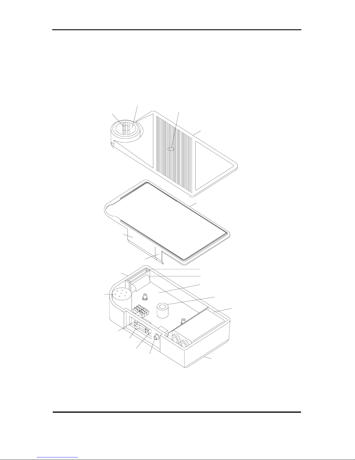
The components identified in Figure 2-1 are described in this
chapter. The field replacea ble units (FRUs) include the housing
gasket, sensor, and battery.
71-0011 — REV E 2-1
95 Series Operator’s Guide
(Hydrophobic
membrane
behind grille)
Sens or P o r t
Buzzer Port
FRONT HOUSING
Operator Controls C over
Earphone Jac k Cover
LCD
Plug-in
Sensor
Zero Button
Power Switch
Span Button
Earphone Jack
HOUSING GASKET
ELECTRONICS ASSEMB L Y:
Display Board
Display Cable
Main Board
Buzzer
Battery
Compartment
REAR HOUSING
Figure 2-1 Components of the 95 Series Gas Monitor
2-2 71-0011 — REV E

Physical Description
Electronics Assembly
The electronics assembly consi sts of the main board, operator
controls (power switch, buttons, and earphone jack), display
board with li qu id cr ystal d isplay (LCD), and t he display cable. If
any of these components fail , contact the factory for repair.
Main Board
All buttons and operator co ntrols are part of the main board.
Control circuitry for other components is also located on the
main boa rd.
ZERO/- and SPAN/+ Buttons
The ZERO/- button alone is used to zero the sensor and decrease
parameter settings. The SPAN/+ button alone is used to set
sensor span and increase parameter settings.
The ZERO/- and SPAN/+ buttons are pressed together to select
setting modes.
Power Switch
Set to the left position (toward the sensor) to turn the instrument
on. Set to the right position (away from the sensor) to turn the
instrument off.
Earphone/Vibrating Alarm Jack
The earphone or vibrating alarm accessory is connected to th is
jack.
71-0011 — REV E 2-3

95 Series Operator’s Guide
Display Board/Display Cable
The display board is attached to th e main board by a
nondetachable ribb on cable.
Liquid Crystal Display (LCD)
The LCD panel is visible through the window in the top of the
housing. A red LED is visi ble through the displa y panel as a
visual indication of alarm cond itions. Display readings are
described in Chapter 3.
Buzzer
The buzzer is mounted on the main board.
Housing/Housing Gasket
The instrument housing is a two- piece plastic c a se held together
by two captive screws. A mylar gasket covers the operator
controls to keep water and dust away from the internal
components. The case is sealed using a detachable rubber gasket
and two flaps to protect the operator controls and earphone/
vibrating alarm jac k.
The letters Z, P, and S on the inside of the flap identify the
position of the ZER O/- b utton, the po wer switch, and the SPAN/+
button, respectively. The arrow next to the P indicates the
direction to m o ve the power switch to t urn th e i nstrum ent o n an d
off.
2-4 71-0011 — REV E
 Loading...