

ThermoForma 900 Series Operating And Maintenance Manual

900 Series
Ultra Low Temperature
Upright Freezers
Operating and Maintenance Manual
Manual No: 7000902 Rev. 0
Model 900 Series _______________________________________________________________________________
i
Read This Instruction Manual.
Failure to read, understand and follow the instructions in
this manual may result in damage to the unit, injury to operating personnel, and poor equipment performance.
CAUTION! All internal adjustments and maintenance must
be performed by qualified service personnel.
Refer to the serial tag on the back of this manual.
The material in this manual is for information purposes only.
The contents and the product it describes are subject to change
without notice. Thermo Forma makes no representations or warranties with respect to this manual. In no event shall Thermo
Forma be held liable for any damages, direct or incidental, arising out of or related to the use of this manual.
MANUAL NUMBER 7000902
0 -- 1/14/03 Original Manual aks
REV ECR/ECN DATE DESCRIPTION By
Models Capacity in
Cubic Feet
Voltage
902 13 230
903 13 120
904 17 120
905 17 230
906 23 230
907 28 230
Double Door Units
991 13 230
992 13 120
993 17 120
994 17 230
995 23 230
Model 900 Series _________________________________________________________________________Warnings
ii
Important operating and/or maintenance instructions. Read the accompanying text carefully.
Potential electrical hazards. Only qualified persons should perform procedures associated with this symbol.
Hot surface(s) present which may cause burns to unprotected skin or to materials which may be damaged by elevated
temperatures
Extreme temperature hazards, hot or cold. Use special handling equipment or wear special, protective clothing.
√ Always use the proper protective equipment (clothing, gloves, goggles, etc.)
√ Always dissipate extreme cold or heat and wear protective clothing.
√ Always follow good hygiene practices.
√ Each individual is responsible for his or her own safety.
Model 900 Series ___________________________________________________________________________Service
iii

Model 900 Series __________________________________________________________________Table of Contents
iv
Table of Contents
Section 1 - Installation and Start-up . . . . . . . . . . . . . . .1 - 1
1.1 Freezer Components . . . . . . . . . . . . . . . . . . . . . . . . .1 - 1
1.2 Control Panel Keys, Displays and Indicators . . . . . .1 - 2
1.3 Operation of the Keypad . . . . . . . . . . . . . . . . . . . . . .1 - 3
1.4 Installing the Freezer . . . . . . . . . . . . . . . . . . . . . . . . .1 - 3
a. Choosing the Location . . . . . . . . . . . . . . . . . . . . .1 - 3
b. Installing the Wall Bumpers . . . . . . . . . . . . . . . . .1 - 3
c. Installing the Shelves . . . . . . . . . . . . . . . . . . . . . .1 - 3
d. Remote Alarm Contacts . . . . . . . . . . . . . . . . . . . . .1 - 3
e. Attaching the Power Cord . . . . . . . . . . . . . . . . . . .1 - 4
f. Connecting the Unit to Electrical Power . . . . . . . .1 - 4
1.6 Freezer Start-Up . . . . . . . . . . . . . . . . . . . . . . . . . . . . .1 - 4
a. Setting the Operating Temperature . . . . . . . . . . . .1 - 4
b. Setting the High Temperature Alarm . . . . . . . . . . .1 - 4
c. Setting the Low Temperature Alarm . . . . . . . . . . .1 - 5
1.7 Run Mode . . . . . . . . . . . . . . . . . . . . . . . . . . . . . . . . . .1 - 5
Section 2 - Calibrate . . . . . . . . . . . . . . . . . . . . . . . . . . . .2 - 1
2.1 Calibrate Mode . . . . . . . . . . . . . . . . . . . . . . . . . . . . . .2 - 1
a. Calibrating the Control Probe . . . . . . . . . . . . . . . .2 - 1
Section 3 - Alarms . . . . . . . . . . . . . . . . . . . . . . . . . . . . . .3 - 1
3.1 Alarms . . . . . . . . . . . . . . . . . . . . . . . . . . . . . . . . . . . .3 - 1
3.2 Probe Failure Alarm . . . . . . . . . . . . . . . . . . . . . . . . . .3 - 1
Section 4 - Maintenance . . . . . . . . . . . . . . . . . . . . . . . . .4 - 1
4.1 Cleaning the Cabinet Exterior . . . . . . . . . . . . . . . . . .4 - 1
4.2 Cleaning the Air Filter . . . . . . . . . . . . . . . . . . . . . . . .4 - 1
4.3 Cleaning the Condenser . . . . . . . . . . . . . . . . . . . . . . .4 - 1
a. Cleaning the Water-cooled Condenser . . . . . . . . . .4 - 1
4.4 Defrosting the Chamber . . . . . . . . . . . . . . . . . . . . . . .4 - 1
4.5 Cleaning the Door Gasket . . . . . . . . . . . . . . . . . . . . .4 - 2
4.6 Cleaning the Vacuum Relief Port . . . . . . . . . . . . . . . .4 - 2
4.7 Replacing the Battery(s) . . . . . . . . . . . . . . . . . . . . . .4 - 2
4.8 Preparing the Unit for Storage . . . . . . . . . . . . . . . . . .4 - 2
Preventive Maintenance . . . . . . . . . . . . . . . . . . . . . . . . . .4 - 3
Section 5 - Factory Options . . . . . . . . . . . . . . . . . . . . . .5 - 1
5.1 BUS (Back Up System) . . . . . . . . . . . . . . . . . . . . . . .5 - 1
a. Installing the vent stack, solenoid and injection
assembly . . . . . . . . . . . . . . . . . . . . . . . . . . . . . . . .5 - 1
b. Installing the Temperature Probe . . . . . . . . . . . . . .5 - 2
c. Connecting the probe/solenoid harness . . . . . . . . .5 - 2
d. BUS Control Panel . . . . . . . . . . . . . . . . . . . . . . . .5 - 3
e. Configuring the Optional BUS . . . . . . . . . . . . . . .5 - 3
f. Setting the Optional BUS Set Point . . . . . . . . . . . .5 - 3
g. System Operation Check . . . . . . . . . . . . . . . . . . . .5 - 3
h. Cleaning the Vent Stack . . . . . . . . . . . . . . . . . . . . .5 - 3
i. Disconnecting the fitting assembly and
transfer hose . . . . . . . . . . . . . . . . . . . . . . . . . . . . .5 - 3
5.2 Chart Recorder . . . . . . . . . . . . . . . . . . . . . . . . . . . . . .5 - 4
a. Installing the chart paper . . . . . . . . . . . . . . . . . . .5 - 4
b. Recorder Calibration . . . . . . . . . . . . . . . . . . . . . . .5 - 4
5.3 Datalogger . . . . . . . . . . . . . . . . . . . . . . . . . . . . . . . . .5 - 5
5.4 Water-Cooled condenser . . . . . . . . . . . . . . . . . . . . . . .5 - 5
5.5 Five Inner Door Option . . . . . . . . . . . . . . . . . . . . . . .5 - 5
Section 6 - Specifications . . . . . . . . . . . . . . . . . . . . . . . .6 - 1
Section 7 - Spare Parts . . . . . . . . . . . . . . . . . . . . . . . . . .7 - 1
Section 8 - Refrigeration Schematics . . . . . . . . . . . . . .8 - 1
Section 9 - Electrical Schematics . . . . . . . . . . . . . . . . .9 - 1
Section 10 - Warranty . . . . . . . . . . . . . . . . . . . . . . . . .10 - 1
Appendix A - Handling Liquid Nitrogen . . . . . . . . . . . .A - 1
Appendix B - Handling Liquid CO
2 . . . . . . . . . . . . . . .B - 1
First Aid . . . . . . . . . . . . . . . . . . . . . . . . . . . . . . . . . . . . . .C - 1
Section 1 - Installation and Start-up
Model 900 Series ___________________________________________________________________Installation and Start-Up
1 - 1
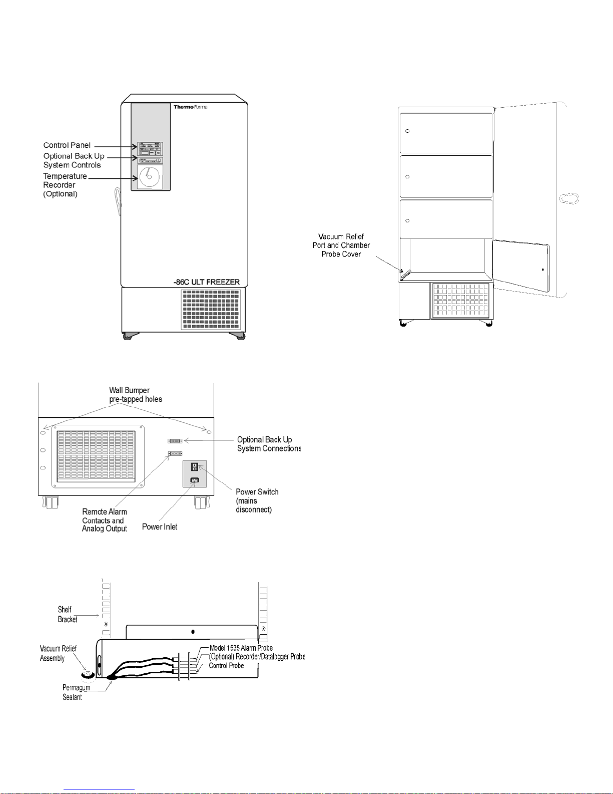
Figure 1-1
Model 900 Series Front
Figure 1-2
Model 900 Series Rear
1.1 Freezer Components
Figure 1-1
• Control Panel - keypad, displays and indicators.
• BUS (Optional Back Up System) panel.
• Optional temperature recorder - 7 day, one pen or
Datalogger.
Figure 1-2
• Remote alarm contacts.
• Power Inlet for power cord connection.
• Optional BUS connections for probe and solenoid.
• Power Switch (mains disconnect).
Figures 1-3 and 1-4
• Vacuum relief port - pressure equalization port.
• Probe cover - houses control, optional recorder or
Datalogger and 1535 alarm (optional) probes.
Figure 1-4
Vacuum Relief and Probe Cover Location
Figure 1-3
Vacuum Relief Port and Probe Cover
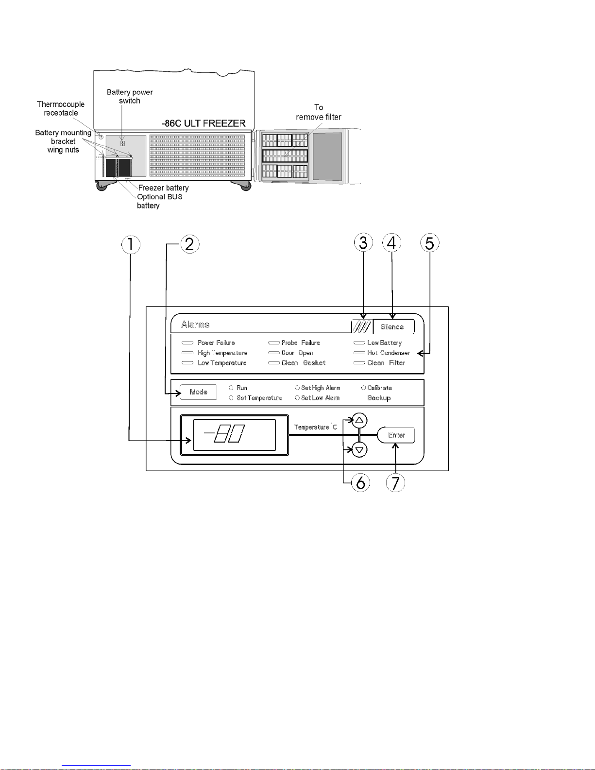
1.2 Control Panel Keys, Displays and Indicators
(See Figure 1-6)
1. Temperature Display - Displays temperature in degrees
Celsius.
2. Mode Select Switch - Used to select Run, Set
Temperature, Set High Alarm, Set Low Alarm, Calibrate,
Backup.
3. Alarm Indicator - Light pulses on/off during an alarm
condition of the cabinet.
4. Silence - Silences the audible alarm.
5. Alarm Panel - indicates the current alarm condition.
6. Up and Down Arrows - Increases or decreases values,
toggles between choices.
7. Enter - Stores the value into memory.
Figure 1-6, Control Panel
1 - 2
Model 900 Series ____________________________________________________________Installation and Start-Up
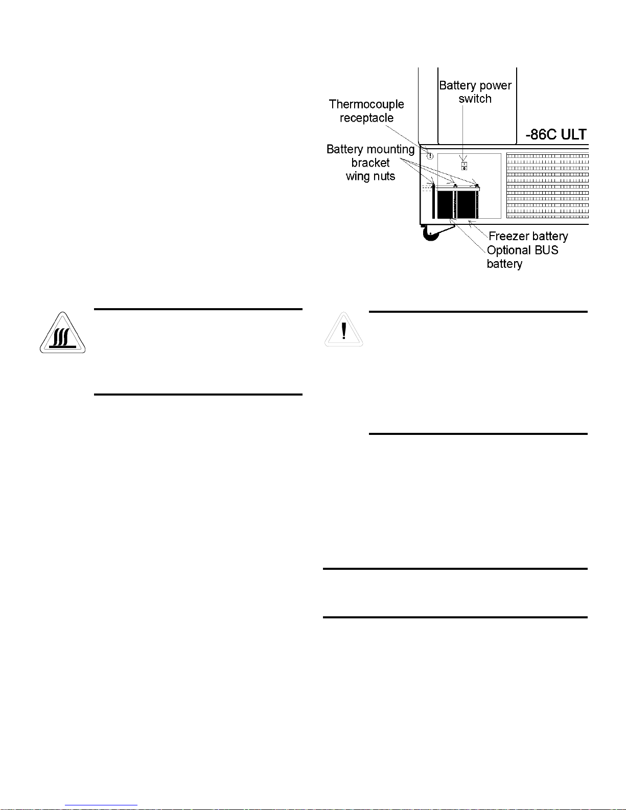
Figure 1-5
Battery(s) location and Switch
Figure 1-5
• Battery mounting bracket wing nuts
(three).
• Battery power switch (freezer and BUS).
• Freezer battery.
• Optional BUS battery.
• Freezer filter location.

1.3 Operation of the Keypad
The 900 Series freezer has five basic modes
which allow freezer setup and operation. Press the
Mode key to scroll through the mode selections.
Up Arrow: Increases or toggles the parameter
value.
Enter: Must press Enter key to save to memory all changed values.
Down Arrow: Decreases or toggles the parameter value.
Silence Key: Press to silence the audible
alarm. See Section 4 for alarm ringback times.
1.4 Installing the Freezer
To remove the freezer from the pallet, use the 7/16"
wrench to remove all the bolts securing the shipping bracket to
the pallet.
Remove the shipping bracket. Remove the ramp
boards from the pallet and place the slotted end over the ramp
brackets on the pallet. The support blocks on the ramps will be
facing down. Before moving the freezer, make sure the casters
are unlocked and moving freely. Align the caster with the ramp
boards. Use adequate personnel to roll the freezer off the pallet.
The freezer can be easily pushed to the desired
approved location, described in Section 1.4.a. If necessary, the
doors and lower front panel may be opened to move the unit
through tight openings. When the freezer is in position, set the
front caster brakes.
a. Choosing the Location
Locate the freezer on a firm, level surface in an area with
an ambient temperature between 18°C and 32°C. Provide ample
room to reach the mains disconnect switch (power switch)
located on the rear of the freezer.
b. Installing the Wall Bumpers
The parts bag, located inside the cabinet, contains the following parts.
Install the bolts into the pre-tapped holes on the back of the
compressor section. Install a neoprene cap on each bolt. Refer
to Figure 1-2 for the locations of the pre-tapped holes.
c. Installing the Shelves
Install the shelf clips into the shelf pilasters (front and
back) at the desired shelf level. Install the shelves in the cabinet
onto the clips.
NOTE: On units having the optional 5 inner door option, refer
to the instructions accompanying the inner door kit.
Model 900 Series ___________________________________________________________________Installation and Start-Up
1 - 3
If tipped more than 45°, allow the unit to set
upright for 24 hours before start up.
The freezer must not be moved with the product
load inside.
Quantity Stock # Description Purpose
2
510016
1/4-20 x 5-1/2” Bolt Wall Bumper
2 380520
Neoprene Cap Cap Protector
For proper ventilation and airflow, a minimum
clearance of 5” at the rear and top and a clearance of 8” on the side of the freezer is required.
Allow adequate space in the front of the freezer
for door opening.
Figure 1-7
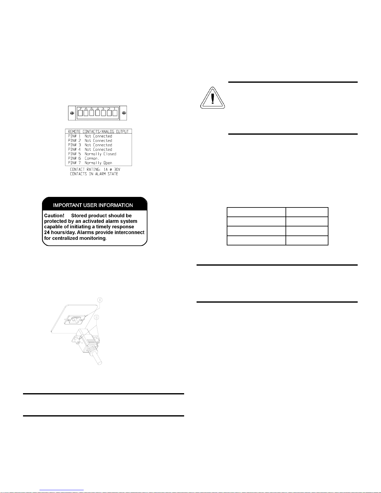
d. Remote Alarm Contacts
The remote alarm provides a NO (normally open) output,
a NC (normally closed) output and COM (common). The contacts will trip on a power outage, high temperature alarm or low
temperature alarm.
The pin configuration for the remote contacts is shown
below (in alarm state).
e. Attaching the Power Cord
Insert the power cord into the power inlet module (A).
Tighten screws (B) on the power cord retainer.
f. Connecting the Unit to Electrical Power
See the serial tag on the side of the unit for electrical specifications or refer to the electrical schematics in this manual.
The freezer should be operated on a dedicated grounded
service. Check the voltage rating on the serial tag of the unit
and compare it with the outlet voltage. Then, with the power
switch turned off, plug the line cord into the wall outlet.
First turn on the freezer power switch. Then open the lower
front door by grasping the bottom left corner. Locate the battery
switch and turn it on. See Figure 1-5. During initial freezer
start-up, the system battery may require charging and the Low
Battery indicator may illuminate.
1.6 Freezer Start-Up
With the freezer properly installed and connected to power,
system set points can be entered. The following set points can
be entered in Settings mode: Control temperature, high temperature alarm set point, low temperature alarm set point, and
(optional) BUS set point. Default settings are shown in the table
below.
a. Setting the Operating Temperature
All 900 Series freezers have an operating temperature
range of -50°C to -86°C, depending on ambient temperature.
The freezer is shipped from the factory with a temperature set
point of -80°C. To change the operating temperature set point:
1. Press the Mode key until the Set Temperature indicator
lights.
2. Press the up/down arrow key until the desired temperature set point is displayed.
3. Press Enter to save the set point.
4. Press the Mode key until the Run indicator lights for
Run mode
If no keys are pressed, the freezer will automatically
return to RUN mode after 5 minutes.
Model 900 Series ___________________________________________________________________Installation and Start-Up
1 - 4
Figure 1-9
If the set point is changed and the low temperature and high
temperature alarms are set 10° from the set point, the alarm
set points will be adjusted automatically to maintain a distance of at least 10° from set point.
Control Set Point -80°C
High Temperature Alarm -70°C
Low temperature alarm -90°C
Optional BUS Set Point -60°C
Figure 1-8
Assure the battery switch is turned on. The
rechargeable batteries require 36 hours to charge
at initial start-up. A “Low Battery” alarm may
occur until the batteries are fully charged. Should
a power failure occur during the initial start-up
period, the electronics will have limited operation.

b. Setting the High Temperature Alarm
The high temperature alarm will activate an audible/visual
warning when the freezer chamber temperature has reached or
exceeded the high temperature alarm set point.
To set the high temperature alarm set point:
1. Press the Mode key until the Set High Alarm indicator
lights.
2. Press the up or down arrow key until the desired high
temperature alarm set point is displayed.
3. Press Enter to save the setting.
4. Press the Mode key until the Run indicator lights for
Run mode
If no control keys are pressed, the freezer will automatical-
ly return to RUN mode after 5 minutes.
Note: The high alarm set point must be set at least 10°C from
the control set point.
c. Setting the Low Temperature Alarm
The low temperature alarm will activate an audible/visual
warning when the freezer chamber temperature has reached or
decrease below the low temperature alarm set point.
To set the low temperature alarm set point:
1. Press the Mode key until the Set Low Alarm indicator
lights.
2. Press the up or down arrow key until the desired low
temperature alarm set point is displayed.
3. Press Enter to save the setting.
4. Press the Mode key until the Run indicator lights for
Run mode
If no control keys are pressed, the freezer will automatical-
ly return to RUN mode after 5 minutes.
Note: The low alarm set point must be set at least 10°C from
the control set point..
Model 900 Series ____________________________________________________________Installation and Start-Up
1 - 5
1.7 Run Mode
The Run mode is the default mode for the freezer. The run
mode will display the cabinet temperature on the temperature
display under normal operating conditions. In addition, the
Run mode allows display of the high stage heat exchange temperature.
This information is scrolled by pressing the up or down
arrow keys. The display will return to the operating temperature
in 10 seconds if no keys are pressed.

Section 2 - Calibrate
2.1 Calibrate Mode
Once the freezer has stabilized, the control probe may need
to be calibrated. Calibration frequency is dependent on use,
ambient conditions and accuracy required. A good laboratory
practice would require at least an annual calibration check. On
new installations, all parameters should be checked after the
stabilization period.
Before making any calibration or adjustments to
the unit, it is imperative that all reference instruments be properly calibrated.
a. Calibrating the Control Probe
Plug a type T thermocouple reader into the receptacle
located inside the lower door (see Figure 1-5). Compare the
control temperature set point to the temperature of the measuring device.
1. Press the Mode key until the Calibrate indicator lights.
2. Press up/down arrow to match the display to calibrated
instrument.
3. Press Enter to store calibration.
4. Press the Mode key to return to Run mode.
Temperature Stabilization Periods
Startup - Allow 12 hours for the temperature in the cabinet to
stabilize before proceeding.
Already Operating - Allow at least 2 hours after the display
reaches set point for temperature to stabilize before proceeding.
During calibration, the temperature display will not be available.
If no keys are pressed for approximately five minutes while
in calibration mode, the system will reset to Run mode.
Model 900 Series _________________________________________________________________________Calibration
2 - 1

Section 3 - Alarms
3.1 Alarms
The Model 900 Series freezer alarms are displayed on the freezer control panel. When an alarm is active, the indicator next to
the alarm description will light and there will be an audible alarm. Press the Silence key to disable the audible alarm for the ringback
period. The visual alarm will continue until the freezer returns to a normal condition. The alarms are momentary alarms only. When
an alarm condition occurs and then returns to normal, the freezer automatically clears the alarm condition.
Model 900 Series ___________________________________________________________________________Alarms
3 - 1
All alarm delays and ringback times are ±30 seconds.
In addition to the alarms listed above, two other conditions
are detected by the controls that will result in an audible and
visual alarm. These alarm conditions are unlikely to occur, and
as such, there are no LED's on the control panel to indicate these
conditions exist.
The first condition is when incorrect voltage is applied to
the freezer. If a 230 V freezer is connected to a 120 V power
source or a 120 V freezer is connected to a 230 V power source,
the electronics will detect that the "Wrong Power" has been
applied. Under this condition, the fans and compressors will not
turn on and an audible and visual alarm will occur. The audible
and visual alarms will remain until the freezer is connected to
the correct power source. The audible alarm cannot be silenced
under this condition.
The second condition is when a "high stage system failure" occurs. This condition is created when the high stage compressor and fans run for 30 minutes and are not capable of cooling the interstage heat exchanger to the proper temperature.
Under this condition, the high stage compressor and fans will
turn off after 30 minutes and an audible and visual alarm will
occur. The audible alarm can be silenced and will ring back
every 15 minutes.
3.2 Probe Failure Alarm
The microprocessor in 900 series freezers continually scans
all probes including the control probe, heat exchanger probe and
condenser probe to ensure that they are operating properly.
Should an error be detected, the "Probe Failure" alarm will occur
as described in 3.1 above. If an error is detected with the control
probe, the high and low stage compressors will run continuously.
As a result, the cabinet temperature will decrease until it reaches
the lowest temperature that the refrigeration system can maintain. If an error is detected with the heat exchanger probe, the
freezer will cycle properly at its temperature set point using a 5
minute step start between the high and low stage compressors.
If an error is detected with the condenser probe, there is no
impact on the performance of the freezer; however, the hot condenser alarm may also occur. Contact the Thermo Forma
Service Department (1-888-213-1790) or your local distributor.
Description Delay Ringback Relay
Power Failure 1 min. 15 min. Yes
High Temperature Alarm 1 min. 15 min. Yes
Low Temperature Alarm 1 min. 15 min. Yes
Probe Failure see 3.2 1 min. 15 min. No
Door Open 1 min. 15 min. No
Clean Gasket 0 min. 3 months No
Low Battery 1 min. 12 hours No
Hot Condenser 1 min. none No
Clean Filter 0 min. 3 months No
Section 4 - Maintenance
4.1 Cleaning the Cabinet Exterior
Wipe down the freezer exterior using soap and water and
a general use laboratory disinfectant. Rinse thoroughly with
clean water and dry with a soft cloth.
4.2 Cleaning the Air Filter (minimum of four times a
year*)
1. Open the front lower door by grasping the bottom left
corner.
2. Locate the grille on the door. See Figure 1-5. Grasp the
middle of the grille material and gently pull out to
remove.
3. Wash the filter material using water and a mild detergent.
4. Dry by pressing between two towels.
5. Install the filter back into the grille and attach the grille.
* The Clean Filter alarm occurs every three months as a
reminder to clean the air filter. Depending upon environmental
conditions, the filter may need to be cleaned or replaced more
frequently. If the filter becomes torn or excessively dirty, a
replacement can be purchased from Thermo Forma. See the
exploded parts list, Section 7, for filter part number. A filter kit
(set of 5) is also available.
4.3 Cleaning the Condenser (minimum of twice a
year*)
1. Open the front lower door by grasping the bottom left
corner. See Figure 1-5.
2. Using a vacuum cleaner, exercising care to not damage
the condenser fins, clean the condenser.
* Depending upon environmental conditions, the condenser
may need to be cleaned more frequently.
a. Cleaning the Water-cooled Condenser
The water-cooled condenser can be cleaned-in-place
by using the CIP procedure. Cleaning solutions can be used,
depending on type of deposits or build-up to be removed.
Do not use liquids that are corrosive to stainless
steel or the brazing material (copper or nickel).
CIP (Clean-In-Place) Procedure
1. Disconnect the unit from the water supply.
2. Drain the unit.
3 . Rinse with fresh water and drain the unit again.
4. Fill with fresh water.
5. Add cleaning agent (solution and concentration dependent on deposits or build-up).
6. Circulate cleaning solution (if feasible).
7. Drain the cleaning solution.
8. Add and circulate a passivating liquid for corrosion inhibition of plate surfaces.
9. Drain this liquid.
10. Rinse with fresh water and drain.
11. Reconnect the water supply and fill the unit.
12 . Return to service.
4.4 Defrosting the Chamber
1. Remove all product and place it in another freezer.
2. Turn the unit off and disconnect it from the power
source.
3. Turn off the power switch (see figure 5-1) to the battery(s).
4. Open all of the doors and place towels on the chamber
floor.
5. Allow the frost to melt and become loose.
6. Remove the frost with a soft cloth.
7. After defrosting is complete, clean the interior with a
non-chloride detergent. Rinse thoroughly with clean
water and dry with a soft cloth.
8. Plug unit in and turn power switch on.
9. Turn the battery power switch to the on position.
10. Allow the freezer to operate empty overnight before
reloading the product.
Model 900 Series ______________________________________________________________________Maintenance
4 - 1
Avoid the excessive use of water
around the control area due to the risk
of electrical shock. Damage to the controls may also result.
4.5 Cleaning the Door Gasket (minimum monthly*)
Using a soft cloth, remove any frost build-up from the gasket and door(s). The Clean Gasket alarm occurs every three
months as a reminder to remove frost build-up from the gasket
and door(s). Press the Silence key to disable the audible alarm.
*The door gasket may need to be cleaned more frequently
if dirt or excessive frost build-up prevents the door from closing properly.
4.6 Cleaning the Vacuum Relief Port (minimum
monthly*)
Using a soft cloth, remove any frost build-up from the vacuum relief, located in the front left corner of the chamber. See
figures 1-3 and 1-4.
4.7 Replacing the Battery(s)
1. To gain access to the battery, open the lower door by grasping the bottom left corner. The battery is rectangular in
shape, located on the front left corner of the compressor
compartment and is secured in place by a mounting bracket
with three bolts.
2. Directly above the battery(s) is the battery power switch.
Turn the battery power switch to the off position.
3. Disconnect the battery connections
4. Remove the three nuts securing the battery bracket.
5. Remove the bracket and old battery, install the new battery
and secure.
6. Reconnect the battery (red to positive and black to negative).
7. Turn on the battery power switch.
8. Close lower panel door.
4.8 Preparing the Unit for Storage
Defrost the unit as described in Section 4.4. This will prepare the unit for storage. Turn off the battery power switch.
Turn off the freezer power switch. Disconnect power to the battery(s) and to the freezer.
If the unit has been in service, turn it off and disconnect the
power cord connector before proceeding with any maintenance.
Model 900 Series ______________________________________________________________________Maintenance
4 - 2
Figure 4-1
The vacuum relief port contains a small heating
element. If the freezer is not disconnected from
the electrical supply or turned off at the power
switch, the heating element will continue to
operate and may cause injury to personnel
cleaning the freezer chamber.
The % of charge can vary depending on the age,
usage and condition of the battery. For a consistent
and dependable charge, replace the battery every 2
years. Replacement batteries must be rechargeable
and are available from Thermo Forma. Refer to
the parts list for stock number and description of
the replacement batteries. Dispose of the used batteries in a safe manner and in accordance with
good environmental practices.

Model 900 Series ________________________________________________________________________________________________________________Maintenance
4 - 3
PREVENTIVE MAINTENANCE
Freezers
Your Thermo Forma equipment has been thoroughly tested and calibrated before shipment. Regular preventive maintenance is important to keep
your unit functioning properly. The operator should perform routine cleaning and maintenance on a regular basis. For maximum performance and
efficiency, it is recommended that the unit be checked and calibrated periodically by a qualified service technician.
The following is a condensed list of preventive maintenance requirements. See the specified section of the instruction manual for further details.
Thermo Forma has qualified service technicians, using NIST traceable instruments, available in many areas. For more information on Preventive
Maintenance or Extended Warranties, please contact us at the number below.
Cleaning and calibration adjustment intervals are dependent upon use, environmental conditions and accuracy required.
Tips:
• Fill an upright by starting at the bottom near the probe and add racks to one shelf at a time. Allow freezer to recover to set point between shelves.
• Fill a chest by starting at the left side near the probe. Filling with room temperature racks will result in a long pull-down time.
• Fill unit with frozen product to help overall performance; frozen water jugs, for example.
• Always make certain the vacuum relief port is free of frost and ice, to allow for timely re-entry into the freezer after a door opening.
•Millcreek Road, Box 649 •Marietta, Ohio 45750 USA •740-373-4763
•USA and Canada 888-213-1790 •Telefax: 740-373-4189 •email: service@thermoforma.com

Model 900 Series ________________________________________________________________________________________________________________Maintenance
Preventive Maintenance for 900 Series Freezers
Refer to Manual Section Action Monthly Yearly Every
2 Years
-- Verify ambient temperature, <90°F ;
-- * Adjust door handle for firm latching, as needed ;
Figure 1-4 for probe location Check and clean probe cover, gaskets, hinges, and vacuum relief port ;
4.5, 4.6 of ice and snow. More frequent cleaning may be
required, depending on use and
environmental conditions.
4.2 Check air filter. Clean or replace as needed ;
1.5.f, 4.7 Check alarm back-up battery. ; ** Replace
-- Check condenser fan motor for unusual motor noise or vibration. ;
2 * Verify and document calibration, at the minimum, annually. ;
4.3 * Clean condenser compartment and wipe off condenser ;
* Qualified service technicians only
** Dispose of properly, according to all state and federal regulations.
4 - 4
Model 900 Series ________________________________________________________________________Factory Options
5 - 1
Section 5 - Factory Installed Options
5.1 BUS - Back Up System (195875, 195877)
Before installation of BUS components, make sure the power
to the freezer is disconnected, the battery switch is turned off
and the freezer has warmed to ambient temperature.
The built-in BUS (back up system) will keep the freezer
chamber temperature below the critical level in the event of a
power or equipment failure. If power to the freezer fails, or temperature increases to the back up alarm set point, the BUS
injects liquefied gas into the chamber to keep the chamber temperature within the specified range.
The BUS operates on an internal 12-volt, rechargeable bat-
tery which is kept charged during normal operation by the integral battery charger.
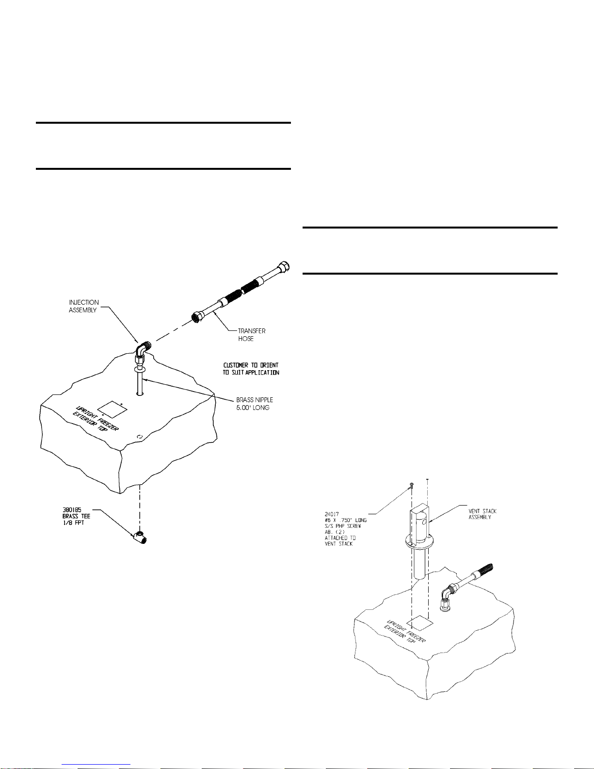
a. Installing the vent stack, solenoid and injection
assembly
1. Install the injection assembly through the 1/2” prepunched hole, directly behind the 2” vent stack hole in
the center of the chamber ceiling. Using a long blade
screwdriver or similar instrument, punch a guide hole up
through the foam insulation to the top exterior ceiling
opening.
CAUTION! Do not use the injection assembly to bore the hole.
The injection assembly could become clogged with insulation
and not function correctly.
Note: Cover the open end of injection assembly with tape to
keep insulation from entering the nipple.
2. Slide 3/8” flatwasher over open end of nipple.
3. Insert the covered end of the injection assembly through
the exterior hole.
4. Remove the tape covering from the end of the nipple and
install the 1/8” NPT brass tee on the open end of the nipple. Place Permagum sealant between the brass tee and
the interior top.
5. Use the 1-3/8” x 20” copper tubing. Remove the plastic
cap from the beveled end (Caution - it is sharp!) and
place the cap on the non-beveled end. Position the
beveled end of the tubing against the foam opening and
use a back and forth twisting motion to cut a hole through
the insulation to the top external opening.
Figure 5-1
Figure 5-2
Model 900 Series ________________________________________________________________________Factory Options
5 - 2
6. Remove the two Phillips head screws securing the metal
bracket on the vent stack assembly.
7. Install the vent stack through the opening and secure it to
the top of the freezer, using screws.
8. Go to the interior and seal around the end of the vent
stack with permagum.
9. Install the solenoid valve to the supply.
When selecting a CO
2 supply cylinder, it must be equipped with
a siphon tube.
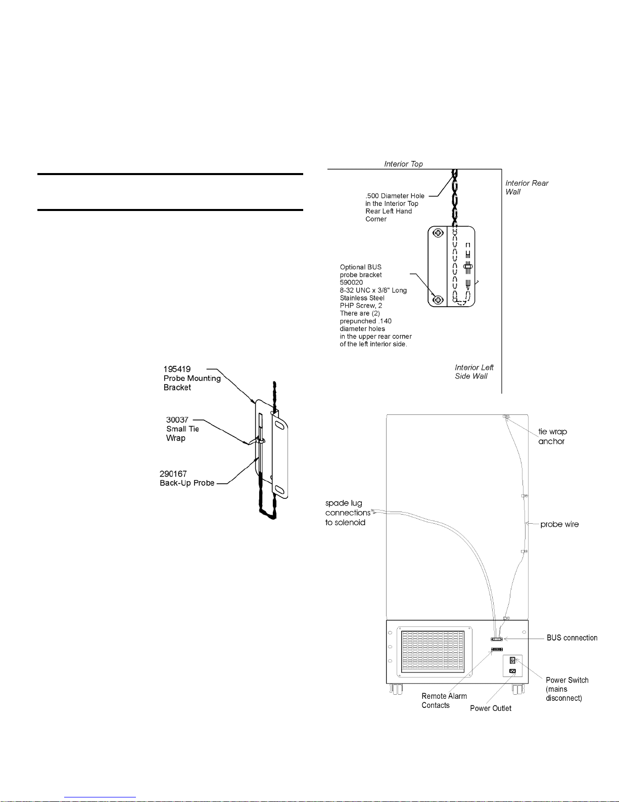
b. Installing the Temperature Probe
10. Locate the 0.500” pre-punched hole in the upper left hand
back corner of the chamber ceiling. Remove the tie wrap
securing the coiled probe/solenoid harness. Uncoil the
probe lead and run the probe tip (approximately 12”)
down through 0.500” porthole (Figure 5-4).
11. As shown in Figure 5-3, thread the small tie wrap
through the openings in the front of the bracket. Secure
the probe on the
back of the bracket with the tie
wrap.
12. Mount the bracket
on the interior left
wall of the freezer
into the prepunched holes
provided. Figure
5-4 shows the
Back-Up probe
mounted on the
interior left side
wall of the freezer.
c. Connecting the probe/solenoid harness
13. Remove the four screws on the freezer back panel and
use them to mount the tie wrap anchors as shown in
Figure 5-5. Secure the probe wire with tie wraps.
14. Plug the solenoid/probe connector into the BUS connection and secure with a screw on the right and left side.
The connector is keyed.
15. Loosen the terminal screws on the solenoid. Slide the
spade lug connectors under the screws and tighten to
secure.
16. Connect power to the freezer. Leave the back-up battery
switch at the OFF position. Turn the freezer on. The
Inject light on the BUS control panel will illuminate but
no injection will occur. The Low Battery indicator may
also illuminate. Once the freezer has stabilized at the
operating temperature, turn the battery switch on.
Figure 5-3
Figure 5-4
Figure 5-5
BUS Operation and Maintenance
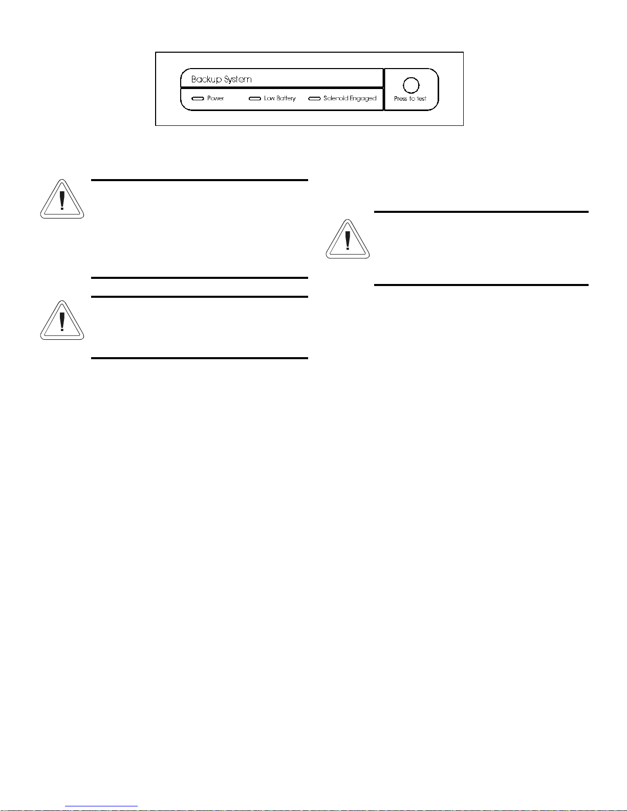
d. BUS Control Panel (see figure 5-6)
Power - indicates the unit has AC power and is operational.
Low Battery - battery charge is low. The battery needs replaced.
Solenoid Engaged - BUS is actively injecting gas into the freezer
chamber.
Press-To-Test - Activates the solenoid and injects LN
2 or CO2
into the freezer chamber as long as the button is depressed. The
solenoid engaged indicator should light. If the Low Battery indicator lights during the test, replace the BUS battery.
e. Configuring the Optional BUS (Back Up System)
The optional BUS can be configured for LN
2 or CO2 supply.
To select the supply type:
1. Press the Mode key until the Backup indicator lights.
2. Press the up or down arrow key. The display will show
OP1 for CO
2 selection and OP2 for LN2 selection.
3. Press Enter to save the setting.
4. Press the Mode key until the Run indicator lights for Run
mode
If no control keys are pressed, the freezer will automatically
return to to RUN mode after 5 minutes.
f. Setting the Optional BUS Set Point
The optional back up system is designed to inject CO
2 or
LN2 into the freezer compartment if the temperature rises above
back up system set point. To set the BUS set point:
1. Press the Mode key until the Set Temperature and Backup
indicators light.
2. Press the up or down arrow key until the desired
BUS set point is displayed.
3. Press Enter to save the setting.
4. Press the Mode key until the Run indicator lights for Run
mode
If no control keys are pressed, the freezer will automatically
return to to RUN mode after 5 minutes.
g. System Operation Check
It is advisable to periodically check the operation of the
entire system. To check the system:
1. Close the valve at the gas source.
2. Set the freezer temperature 12 - 15°C higher than the normal operating temperature.
3. Listen for the gas valve to open as the freezer temperature
rises to the Back-Up unit set point.
4. Check the gas flow by momentarily opening the valve at
the gas source.
5. Turn off the flow of gas.
6. Reset the freezer temperature to the normal operating temperature, and allow the temperature to stabilize.
7. When the freezer has stabilized at the operating temperature, open the valve at the gas source.
h. Cleaning the Vent Stack
Routinely check the vent stack for frost or ice build-up. The
type of frost that forms in the vent stack is generally very soft
and may be easily removed with a bristle brush or soft cloth. if
ice build-up has occurred, a complete defrost may occasionally
be required. See section 4.4 for freezer defrost instructions.
i. Disconnecting the Fitting Assembly and
Transfer Hose
To disconnect the freezer back-up from the gas supply:
1. Close the supply valve.
2. Depress the test button on the BUS control box to remove
the gas from the line.
3. Slowly disconnect the fitting assembly from the supply (in
the event that any gas remains in the line).
Model 900 Series ____________________________________________________________________Factory Options
5 - 3
WARNING! When activated, this unit injects liquid nitrogen or carbon dioxide. Liquid Nitrogen
can cause serious freezing (frostbite) if it comes in
contact with unprotected skin or eyes. Nitrogen
suppresses oxygen levels and may cause suffocation if area is not well ventilated. Refer to
Appendix A for the proper handling of liquid LN2.
Carbon Dioxide gas suppresses oxygen levels and
may cause suffocation if area is not well ventilated. Refer to “Handling Liquid CO
2 in Appendix B
of this manual.
Figure 5-6
The BUS set point must not be any colder than
the high temperature alarm set point. (See section
1.6.b). If the back-up system is installed with CO
2,
then -65°C is the coldest BUS set point that can
be used.
 Loading...