

ThermoFLUX Pelling 25, Pelling 100, Pelling 35, Pelling 50, Pelling 75 User And Maintenance Manual
ThermoFLUX d.o.o., Bage br. 3, 70101 Jajce, Bosna i Hercegovina, Tel/Fax: 030–657-100
www.thermoflux.ba
tfinfo@thermoflux.ba
USER AND MAINTENANCE MANUAL
2

3
ThermoFLUX
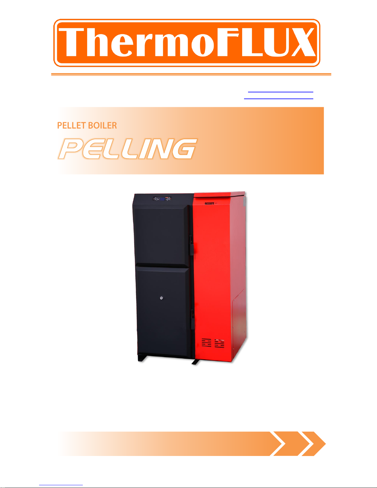
Pelling
Content:
1 Notes on the manual .................................................................... 5
1.1 Introduction .......................................................................................................... 5
1.1.1 Easy and safe operation ...................................................................................... 5
1.1.2 Reading the manual ............................................................................................ 5
1.1.3 Technical changes .............................................................................................. 5
1.1.4 Copyright .......................................................................................................... 5
2 Safety notes ................................................................................ 6
2.1 Proper use ............................................................................................................ 6
2.1.1 Basic principles .................................................................................................. 6
2.1.2 Using the boiler .................................................................................................. 6
2.1.3 Permissible fuel for the Pelling boilers ................................................................... 6
2.1.4 Recommended wood pellets ................................................................................. 6
2.2 Warnings and safety symbols used .......................................................................... 7
2.3 Other risks of the side effects .................................................................................. 8
2.4 Duty to inform ....................................................................................................... 8
2.5 Safety devices ....................................................................................................... 8
3 Installation and commissioning of the boiler .................................. 10
3.1 Conditions ........................................................................................................... 10
3.2 Chimney and flue gas pipes ................................................................................... 10
3.3 Minimum distances of the boiler from wall and objects .............................................. 11
4 Functional description ................................................................. 12
4.1 General overview .................................................................................................. 12
4.2 Pellet boiler PELLING ............................................................................................. 13
5 Funcioniranje kotla ..................................................................... 15
5.1 Overview of the controls and display and their basic functions .................................... 15
5.2 Principle of boiler operation .................................................................................... 17
5.3 Schematic representation of the menu control .......................................................... 18
5.3.1 Clock adjustments ............................................................................................. 20
5.3.2 Adjustments of the programmed on and off mode ................................................. 21
5.3.3 Boiler has possibility for programmed on and off mode during a day and this option is
regulated on three ways: .............................................................................................. 21
5.3.4 LANGUAGE OPTIONS ......................................................................................... 23
5.3.5 STAND BY mode ............................................................................................... 23
5.3.5.1 STAND BY mode with installed sensor for water temperature ............................... 23
5.3.5.2 STAND BY mode with room thermostat connected .............................................. 24
5.3.6 Option Buzzer ................................................................................................... 25

4
ThermoFLUX
Pelling
5.3.7 Filling of spiral dispenser .................................................................................... 25
5.3.8 STATE OF THE BOILER ....................................................................................... 25
5.3.9 Technical settings .............................................................................................. 25
5.3.10 FUEL TYPE..................................................................................................... 26
6 Ignition and shutting down of boiler ............................................. 27
6.1 Ignition ............................................................................................................... 27
6.2 Shutting down of boiler ......................................................................................... 28
6.3 Boiler power adjustments ...................................................................................... 28
6.4 Adjustment of water temperature in boiler ............................................................... 29
6.5 Modulation ........................................................................................................... 29
6.6 Cleaning of FIRE-POT ............................................................................................ 30
6.7 Burning of wood ................................................................................................... 30
7 Cleaning and maintenance .......................................................... 33
7.1 Daily cleaning ....................................................................................................... 33
7.2 Weekly cleaning ................................................................................................... 34
7.3 Monthly cleaning................................................................................................... 35
8 Connection options ..................................................................... 37
8.1 Hydraulic schemes for connection ........................................................................... 37
8.2 Scheme for electric connection ............................................................................... 39
9 Alarms ...................................................................................... 41
10 Instruction about safety removal and proper disposal of boiler ...... 43
10.1 Disposal .............................................................................................................. 43
11 Guarantee .............................................................................. 44
11.1 Guarantee period .................................................................................................. 44
11.2 Guarantee terms .................................................................................................. 44
11.3 Exemption from the guarantee ............................................................................... 44

5
ThermoFLUX
Pelling
1 Notes on the manual
1.1 Introduction
1.1.1 Easy and safe operation
This manual contains important information for proper and safe operation of the
Pelling boilers. Following these instructions you will avoid danger and repair costs,
and also increase the operational life of the boiler.
1.1.2 Reading the manual
This manual must be read and applied by everyone who operates or works on the
Pelling boiler.
1.1.3 Technical changes
ThermoFLUX continuously develops and improves its boilers. The information in this
version is correct at the time of going to press. All details in this manual on
standards and regulations should be checked before use and should be compared
with the installed boiler. We reserve the right to make changes which may then
deviate from the technical details and illustrations in this manual.
1.1.4 Copyright
Written agreement is required from Thermo FLUX d.o.o. for any reprints,
storage in a data–processing system or transmission by electronic, mechanical
or any other means, for copies and publications, in whole or in part.

6
ThermoFLUX
Pelling
2 Safety notes
2.1 Proper use
2.1.1 Basic principles
Pelling boiler was built in accordance with safety regulations. However, its use can
result in the injury or death of the user and/or third part and in impairments to the
boiler itself or to other material goods.
2.1.2 Using the boil er
Use the boiler only when it is in perfect condition. Use it properly, as described in this
manual. Stay aware of the safety and of the dangers involved. Have any faults which
can impair safety immediately fixed.
The boiler was designed to burn wood pellet and wood. The manufacturer will accept
no responsibility for any damage resulting from improper use. Proper use includes
maintaining the installation, operation and maintenance specified by the
manufacturer. The user may only enter or change the operating values specified in
this manual. Any other entries will affect the boiler's control program and operation,
which can lead to a malfunction.
2.1.3 Permissible fuel for the Pelling boi lers
Only wood pellets and wood are permissible as fuel for the boiler. Wood pellets are
pressed into a cylindrical shape. They consist of untreated sawdust from the wood
processing industry as well as unprocessed forestry waste. They have a standardized
diameter and length and very low water content.
2.1.4 Recommended wood pellets
Thermo FLUX d.o.o. recommends wood pellets with a diameter of 6 mm and a
length of 10 - 30 mm.
Other requirements on the fuel result from either standard O-Norm M 7135,
DIN plus 51731,
UNI CEN/TS 14961
Pay particular attention to the wood pellet quality.
7
ThermoFLUX
Pelling
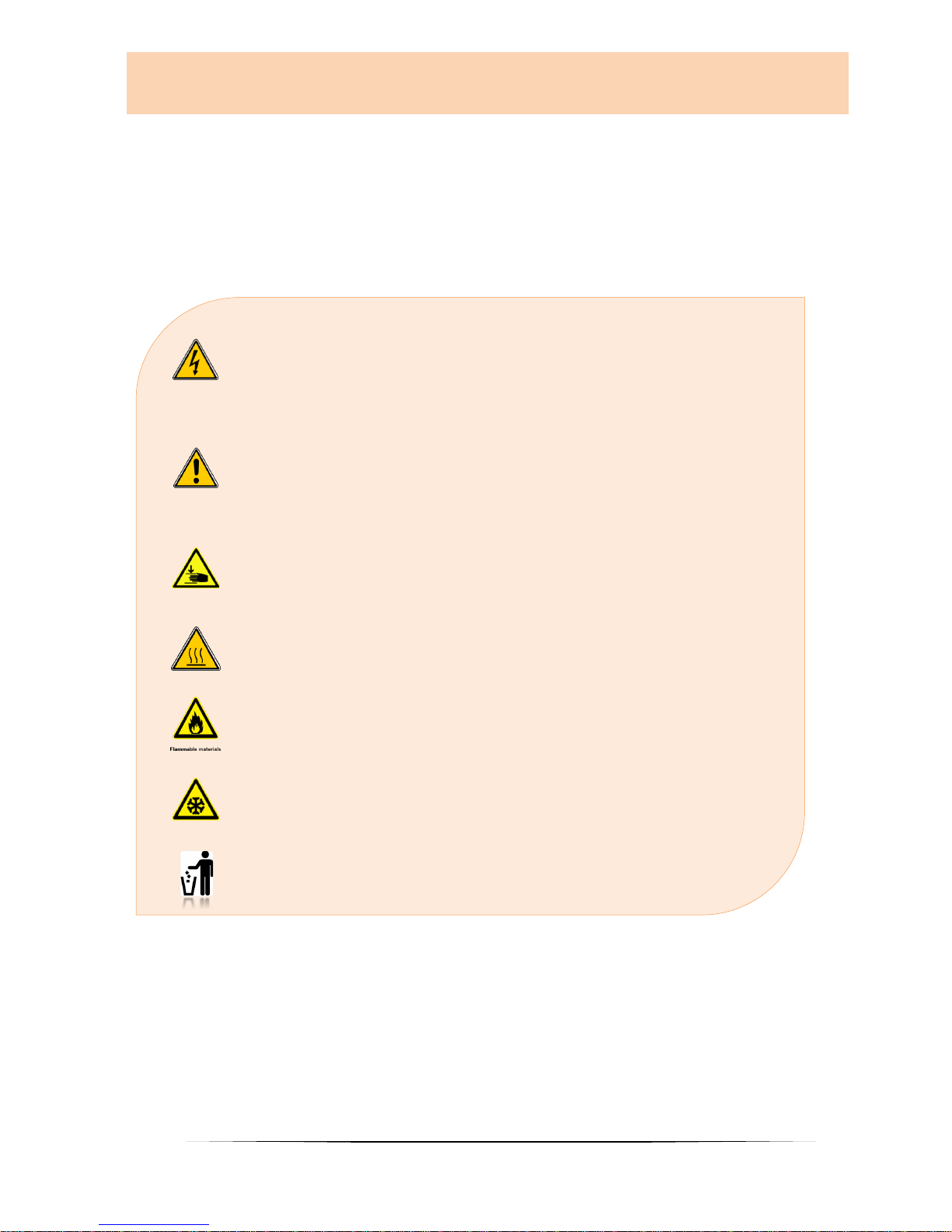
2.2 Warnings and safety symbols used
DANGER OF ELECTRIC SHOCK.
Work on areas marked with this symbol may only be done
by a qualified electrician.
WARNING!
Warning about a dangerous location. Work on areas marked
with this symbol can lead to serious injuries or to extensive
material damage.
CAUTION!
Hand injuries. Work on locations marked with this symbol
can lead to hand injuries.
CAUTION!
Hot surface. Work on locations marked with this symbol can
lead to burns. .
CAUTION!
Danger of fire. Work on locations marked with this symbol can
lead to a fire.
CAUTION!
Frost danger. Work on locations marked with this symbol can
lead to frost damage.
Notes on disposal.
8
ThermoFLUX
Pelling
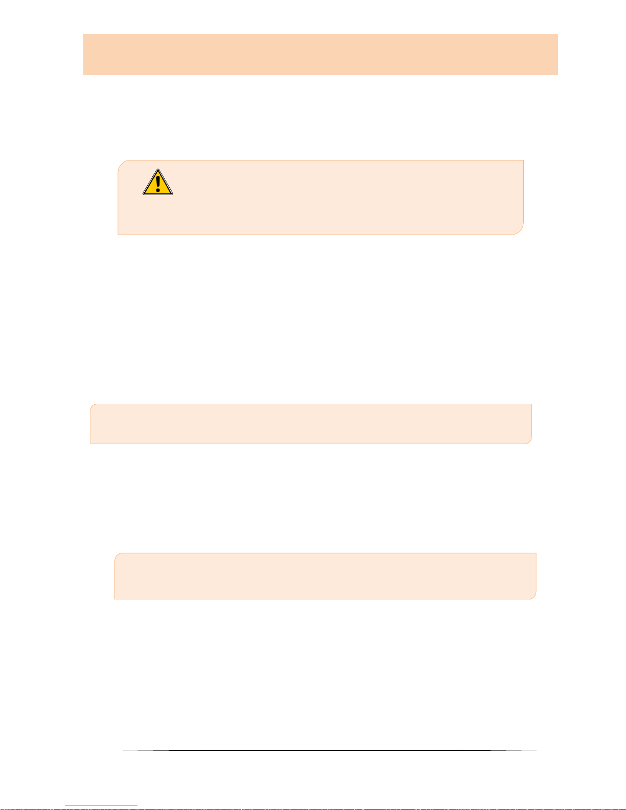
2.3 Other risks of the side effects
Despite the precautions taken there are also certain risks of side effects:
DANGER OF CARBON MONOXIDE.
If the boiler is running during cleaning time may occur
transmission of CO through the open door. Do not open the
door longer than necessary.
2.4 Duty to inform
Reading the manual
Everyone who works on the boiler must have read the Use and maintenance manual
before starting work and, in particular, have read the second chapter „Safety notes“.
This holds especially true for persons who only occasionally work on the boiler e.g.
when cleaning or maintaining the boiler. This manual must be kept ready to hand at
the boiler's installation location.
Pay particular attention to the applicable local standards and guidelines.
2.5 Safety devices
Boiler is equiped with safety devices that in case of unexpected situations
stop the power supply and thereby stop the operation boiler.
Boiler electronic regulation: operates directly and stops the operation of the boiler
until it cools down.
* In case of the suction fan failure, failure of the motor for auger (doser), black out
(if the blackout was longer than 10 seconds), an unsuccessful firing.

9
ThermoFLUX
Pelling
Fuse F 4 A 250V : Fast fuse , protects the boiler from large voltage changes of
electricity and short circuits inside the boiler.
Safety thermo switch (STB) : intervenes by breaking the circuit in the boiler
(automatically stops motor of the auger and exhaust gasses fan) if the boiler
temperature reaches the limit of 95 °C.

10
ThermoFLUX
Pelling
3 Installation and commissioning of
the boiler
Commissioning system in the operation is performed by personnel
authorized by ThermoFLUX Ltd or autorized seller.
Commissioning includes referral to operation with the basic operations and
maintenance of the boiler. Authorized service for the first start, must control the
functioning of the boiler at least during one full operating cycle.
Danger from material and body due to improper
commissioning. If the commisioning is performed by
unautorished personel, it may cause damage to the boiler
and heating system.
3.1 Conditions
The following conditions must be fulfilled before the system is put into
operation.
Turn OFF electrical power.
Check mechanical connections
Check that all components are properly connected
Check that all mechanical components are connected.
Check whether combustion chamber properly seated
Check hidraulical connections
Check whether the circulation pump and the mixing valve is properly
connected.
Check whether the safety equipment properly connected.
3.2 Chimney and flue gas pipes
The chimney should be calculated and constructed in accordance with the EN
13384-1 standard.
The venting of flue gas must be done in accordance with all applicable laws
including those related to dimensions of the chimney and materials used for its
production. Flue gas channel should be made of adequate materials, such as steel
tubes, with various sealing.
11
ThermoFLUX
Pelling
In any case, materials that could potentially catch fire, e.g. wooden planks,
beams, cloth, should be adequately protected with non-combustible material. For
the sake of parity of dimensions, chimneys that are round in shape of the inner
part should have an advantage over the rectangular-shaped chimneys.
Too small inner zone can cause irregular flow from the boiler to the top which
could lead to poor boiler performance and excessive exhaust gas production that
discharges the exhaust gas to the environment. Gas flue pipe should be
permanently installed and it would be good to make safety door which would
enable the cleaning of inner parts, especially the horizontal parts.
Smoke pipe should be installed fixed. It would be good to leave safety gates that
could do the interior cleaning, especially in their horizontal parts.
You should avoid as much as possible horizontal mounting parts. Horizontal parts
must have a slope of at least 3% upwards.
Length of the horizontal part should be minimal and in any case not more than 3
meters.
ALL PARTS OF THE FLUE GASN PIPE NEED TO BE SECURED AND REPLACEABLE
IN ORDER FOR INTERNAL CLEANING.
AVOID MULTIPLE HORIZONTAL DEVIATION AND ANGLES.
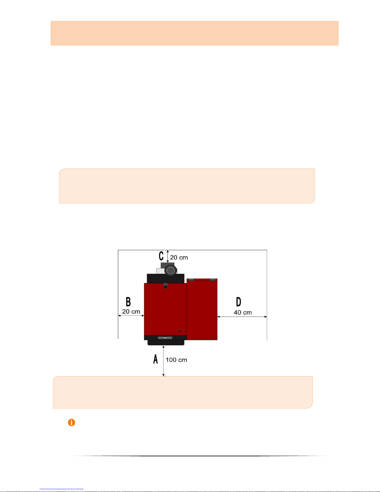
3.3 Minimum distances of the boiler from wall
and objects
A – minimum distance front - 100 cm
B – minimum distance from side (BOILER BODY) - 20 cm
C – minimum distance back side- 20 cm
D – minimum distance from side (SILO) - 40 cm
ThermoFLUX leaves itself the right to later perform changes without notice.
12
ThermoFLUX
Pelling
4 Functional description
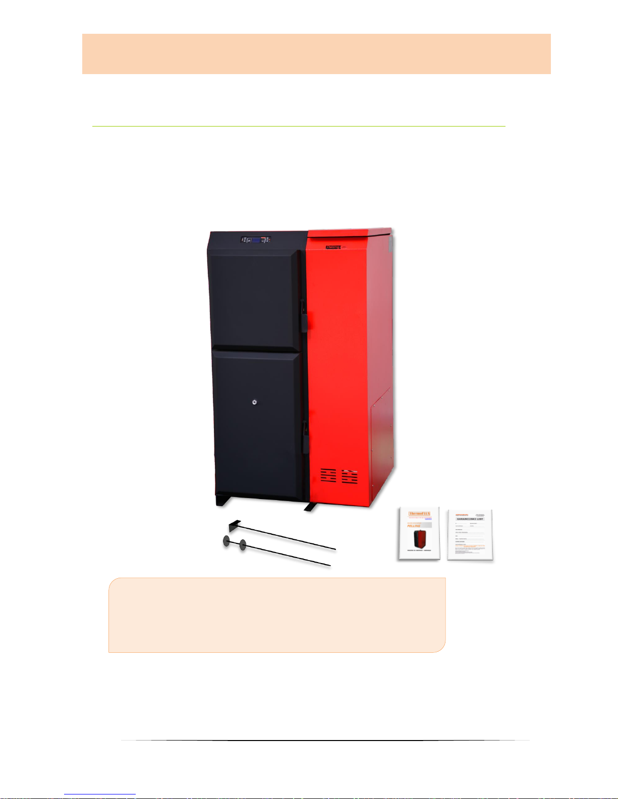
4.1 General overview
Accompanying material
1 – Tools for the pipeline and firebox cleaning
2 – Instructions booklet
3 – Guarantee

13
ThermoFLUX
Pelling
4.2 Pellet boiler PELLING
1. Combustion burner
2. Combustion chamber
3. Heater
4. Exhaust fan
5. Control unit
6. Silo
7. Dispenser

14
ThermoFLUX
Pelling
In the Pelling boiler the pellets introduced into the combustion burner 1. They are
automatically ignited with an electric heater 4. Burnt pellet (ash) is collected in the
ash pan 3. which is placed under the combustion burner. The air necessary for
combustion is supplied to the combustion burner.
Through sensors:
1. The boiler power is adjusted to the heat requirement.
2. The boiler efficiency is optimised.
3. Flue gases are optimised.
Technical data:
RB
Pelling 25
Pelling 35
Pelling 50
Pelling 75
Pelling100
1
Heat output
kW
8-25
11-35
20-50
30-75
50-100
2
Water content
l
60
90
120
154
181
3
Boiler weight
kg
267
348
392
494
580
4
Inlet / Outlet water
connection
"
1''
5/4''
5/4''
6/4''
2''
5
Flue gas temperature
C
cca 160
cca 160
cca 160
cca 160
cca 160
6
Max water
temperature
C
85
85
85
85
85
7
A Height to center of
flue pipe
mm
1420
1600
1630
1750
1770
8
B Depth
mm
948
948
1098
1240
1390
9
C Width without silo
mm
410
510
510
560
650
10
D Height
mm
1245
1385
1385
1528
1532
11
E Width with
standard / maxi silo
mm
710/910
810/1010
810/1010
1060
1150
12
F Flue pipe diameter
mm
120
120
120
150
150
13
G Height of Inlet /
Outlet
mm
88.2/1282
85/1415
85/1415
70/1568
75/1532
14
Pellet silo capacity
standard / maxi
kg
75/135
95/151
110/185
270/ -
290/-
15
Electric consumption
nominal/ max
W
175/350
175/350
190/380
190/380
240/480
16
Min/max water
temperature
C
55/85
55/85
55/85
55/85
55/85
17
Door opening (h x w)
mm
250x315
350x375
350x375
380x440
484x466
18
Min/max consumption
of pellet
kg/h
1,6/5.5
2,2/7,5
3,1/11.1
4,9/16.6
6,1 /22.2
19
Max. Length of
firewood logs
mm
400
400
500
500
500
20
Fuel
_
pellet/wood
pellet/wood
pellet/wood
pellet/wood
pellet/wood
21
Flue exhaust direction
_
up
up
up
up
up
22
In accordance to
EN
EN 303-5
EN 303-5
EN 303-5
EN 303-5
EN 303-5

15
ThermoFLUX
Pelling
5 Function of boiler
5.1 Overview of the controls and display and
their basic functions
Button
Description
1 -
Increasing temperature and program functions
(adjusting days, time...)
2 -
Decreasing temperature and program functions
(adjusting days, time...)
3 -
Changing – accepting program
4 -
ON / OFF, program exit
5 -
Decreasing power, navigate through the menu
6 -
Increasing power navigate through the menu
1
2
3
4
5 6 7 8 9
10

16
ThermoFLUX
Pelling
Display
8
Info
9
Clock
10
Water temperature indicator
Regulation on the boilers ''Pelling'' is most important electronic component.
It is consisted of key controling modul set under the cover of the boiler and
controling unit with display set on the front side of the boiler. With controling
unit it is possible to control functions of the boiler and also to check information
about present state of the boiler.
Due to the possibilty to work in 5 (five) different powers, regulation can
satisfy needs to increase or decrease heating by automatic adjustment of
power.
If there is a need to increase power, this is registered by regulation and
regulation gives a signal to increase power by adding more pellet as well as
proportional increase of air flow in the burning basket.
When desired temperature is reached (need for heating energy is satisfied)
regulation is decreasing power ( modulates ), or when room thermostat gives
signal that set temperature is reached, boiler then goes into SHUT DOWN mode
(if mode STAND-BY is ON )
7
When mark is visible
Clock
programmed ignit. active
Heater
heater active
Pelet dosage
auger active
Smoke fan
fan active
Primary air fan
fan active
Circulating pump
pump active
Alarm
alarm active
7

17
ThermoFLUX
Pelling
5.2 Principle of boiler operation
Principle of the boiler operation is very simple.
When button for start is pressed boiler goes into IGNITION MODE. START is
displayed, and after that PELLET IGNITION. Usually this phase lasts for 5-15 minutes
depending on type of the boiler and pellet quality. At that point dosing system is
activated, igniter and suction fan. Dispenser is making initial dosing of pellet into
burning basket. At the same point igniter starts to ignite pellet and suction fan is on
and is making necessary underpressure needed for combustion. When temperature
sensor for flue gasses detects that temperature in the chimney has reached
necessary value, regulation then changes working mode of the boiler into FLAME
STABILIZATION.
This phase (FLAME STABILIZATION) lasts for 2-3 min. (depending on the type of the
boiler and in this phase igniter goes off. After flame stabilization, boiler goes into the
normal working mode and changes power from power 1 to set power. On display is
written WORK. On the right side set power is displayed and in the last
Start
PELLET IGN.
Flame
stabilization
WORK

18
ThermoFLUX
Pelling
5.3 Schematic representation of the menu
control
By pressing button SET we enter general menu.

19
ThermoFLUX
Pelling

20
ThermoFLUX
Pelling
5.3.1 Clock adjustments
Clock adjustments can be done on following way:

21
ThermoFLUX
Pelling
5.3.2 Adjustments of the programmed on and off
mode
5. 3 .3 Bo il e r h as po s s i bi l it y f o r p ro gra mm e d o n an d o f f m od e
du r in g a da y a nd t h is op t io n i s r eg u la t ed o n th re e w a ys :
1. DAY PROGRAM, in this mode we can set 2 (two) different times
for ignition and shutting down of the boiler.This applies to all
days in the week.(Scheme 2)
2. WEEK PROGRAM, in this mode we can set 4 (four) different
times for ignition and shutting down. In this mode, we can
choose day in the week (MON-SUN) in which we want boiler to
work for each program (Scheme 3)
3. SUN-SAT PROGRAM, in this mode we can set 2 (two) different
times forignition and shutting down, but onl for SATURDAY and
SUNDAY. (Scheme 4)
Sheme1.

22
ThermoFLUX
Pelling
Shema 2. Shema 3. Shema 4.

23
ThermoFLUX
Pelling
5.3.4 LANGUAGE OPTIONS
Language settings are adjusted by pressing the SET button,and after that
by pressing of button 5 or 6 we choose option MENU 03-LANGUAGE.
By pressing of the SET button language menu is opened
(italian,english,german,french, croatian...) in which we can choose
desired language by pressing button 1 or 2.
When desired language is choosen, confirmation is to be done by pressing
button SET.
Returning back is done by pressing button 4 (ON/OFF)
5.3.5 STAND BY mode
STAND BY is used in two ways..
In the case that boiler shuts down because desired temperature is reached
(set ON ) ,
In the case that boiler modulates when desired temperature is reached (set
OFF).
Function STAND BY can be set ON or OFF on following way:
STAND BY mode is activated by pressing button SET, and afterwards by
pressing buttons 5 and 6 we choose desired item in the MENU 04 –
STAND BY MODE.
By pressing SET we are opening options ON or OF (choosed by pressing of
buttons 1 or 2, and confirmed by prissing of button SET).
5.3.5.1 STAND BY mode with installed sensor for water temperature
Connection for room thermostat is delivered overbridged, which
means that contact is closed.
1. FUNCTION STAND-BY SET ON
In the case that function STAND-BY is activated (ON), boiler will shut down
when desired temperature is reached and above by 2 degrees C, and after 2
minutes of time pause (set in factory) TON-WAITING COOLING is displayed. If
temperature do not decrease below set temperature during 4 (four) minutes,
on display is written TON-REQUEST WAITING.

24
ThermoFLUX
Pelling
When temperature of the water in boiler is below set temperature by 2
degrees C, boiler will start again with ignition mode and it will work on set
power.
2. FUNCTION STAND-BY SET OFF
In the case that function STAND BY is not activated (OFF) , and that
connection for the room thermostat is not overbridged, boiler will always work
in power 1 no matter which power is set.
In the case that function STAND BY is not activated (OFF), and connection for
room thermostat is overbridged (set in the factory) boiler will work in the
power chosen by the user, and when desired temperature is reached will go
into modulation mode. Boiler will shut down only if the temperature in the
boiler is 80 degrees C, and will start again when temperature drops down below
desired temperature.
5.3.5.2 STAND BY mode with room thermostat connected
1. FUNCTION STAND-BY SET ON – room thermostat shuts down
boiler
When room thermostat sends signal that desired temperature in the room is
reached (contact is open/temperature is reached) boiler will shut down after
2 minute (factory settings- in the case that temperature in the room
changes all to prevent constant turning on and off of the boiler) on display is
written tOFF-WAITING REQUEST.
When room thermostat gives signal that room temperature is low (contact
closed/ temperature needs to be reached) boiler will start ignition and on
display is written tON.
Remark: Boiler functioning primarily depends on temperature of the water
inside of boiler and factory settings inserted. If boiler is in state of WAITING
COOLING (water temperature is reached), eventual request of the
thermometer will be ignored.
2. FUNCTION STAND-BY SET OFF – room thermostat gives signal
to the boiler to work in POWER 1
In the case that function STAND BY is not activated (OFF) boiler will work in
power chosen by the user and when desired temperature is reached boiler will
modulate (will not shut down but working power will change to lowest).
Boiler will shut down only if temperature of the water in the system is 80
degrees C, and on display is written WAITING COOLING. Boiler will start
again when temperature in the system drops down below set temperature.

25
ThermoFLUX
Pelling
5.3.6 Opti on Buzzer
BUZZER is used in the case that user want to hear sound signal from the boiler
in the case of activated alarm ( set ON ), or without sound signal ( set OFF ).
Option BUZZER is activated by pressing of button SET, and after that
with buttons 5 or 6 we choose item MENU 05- OPTION BUZZER.
By pressing of the button SET choice ON or OFF is opened (with buttons 1
or 2 we are selecting option and confirmation is done by pressing SET ).
5.3.7 Filling of spiral dispenser
Filling of spiral dispenser with pellet is done when pellet is loading for the
first time or in the case of empty silo. Process of filling of spiral dispenser is set
to 90 seconds .
Filling of spiral dispenser is done by pressing of button SET, and after by
pressing buttons 5 or 6 we choose MENU 06-FILLING OF SPIRAL.
Filling os spiral is activated by pressing of button SET.
Prior to start up of the boiler, check combustion chamber. There is a
big possibilty that there are some leftovers from pellet in it while
spiral dispenser was filled. Combustion chamber needs to be empty
and then ignition process can be initiated.
5.3.8 STATE OF THE BOILER
State of the boiler is only of informational character and its purpose is to give
us information about condition of the boiler. On display information is randomly
changed about water temperature in the boiler, flue gasess temperature, fan
RPM, etc.
To enter this option press SET, after that with buttons 5 or 6 we choose
MENU 07 – STATE STOVE.
5.3.9 Technical settings
TECHNICAL SETTINGS are foreseen for authorised personnel only.

26
ThermoFLUX
Pelling
5.3.10 FUEL TYPE
FUEL TYPE is part of the menu where user is changing information about
used fuel type. By default fuel is SET to PELLET, and in the case that we
want to use wood, it is necessary to change this option to WOOD.
Selection of thy fuel type is done by pressing SET, and after that 5 or 6
we choose MENU 09 – FUEL TYPE.
By pressing SET,option for desired type of fuel is opened (PELLET or
WOOD).Selection is made by buttons 1 or 2. After choosing of fuel type,
confirmation of selection is done by pressing button SET.

27
ThermoFLUX
Pelling
6 Ignition and shutting down of boiler
Ignition sequence and description of regulation
Basic function of the regulation is to secure reliable ignition of used fuel, optimal
conditions for combustion and controled sequence for shutting down. Depending on
working power, and complexity of the heating system, parameters are read and
controled differently. Some of the most important ways of working are described
with relevant values.
Before start up following things needs to be checked:
Silo needs to be filled with pellet
Silo doors needs to be closed
Combustion chamber/basket needs to be cleaned
Ash pot needs to be clean
All doors on boiler needs to be closed
Boiler must be connected to electric source - 220 V, 50 Hz
6.1 Ignition
Press and hold button 4 for 3 (three) seconds. Boiler will start with
ignition.
START will be displayed, on the left side of display we see that igniter and
suction fan are activated. Mark tON is showing that room thermostat is
connected or overbridged on conncection for room thermostat (deafult).
After that, on display we have text LOAD PELLET and on the left side we
see that feeding of pellet is activ.

28
ThermoFLUX
Pelling
After ignition of pellet, and after tempereture of flue gasses raise on value
of 55 °C, regulation receives signal that fire is on and boiler continues to
work with set values.
6.2 Shutting down of boiler
Press and hold button 4 for 3 (three) seconds. On display it is written
CLEANING FINAL. Suction fan is working on maximum, feeding of pellet is stopped.
6.3 Boiler power adjustments
During working phase, it is neccesary to set working power in which we
want boiler to work.
Adjustments of the working power is possible in the range from 1-5, and
selection of desired power is done by buttons 5 or 6 (*1). On upper line it
is writen WORK and set power (*2), and present working power sign is
blinking on lower line on the right side (*3).
Power 1 is lowest and power 5 is highest power.

29
ThermoFLUX
Pelling
Regulation on the boiler is set in the way to modulate (power goes into
lowest one ) it's work when 4 C is reched below set temperature – read
6.5 Modulation
6.4 Adjustment of water temperature in boiler
Adjustment of water temperature in the boiler is done by pressing button
1 or 2 (*1). Temperature can be set in range from 55 °C to 80 °C (*2).
These are factory settings and it is not possible to set lower or higher
temperature then above mentioned.
6.5 Modulation
When water temperature in boiler is near to set value regulation begins to modulate
its work and changes power to lowest. Modulation starts 4 °C below set temperature.
EXAMPLE: We have adjusted water temperature on 73°C and power 5, regulation will
work in power 4 when temperature is 70°C, on 71°C boiler will work in power 3, on
72°C power is 2 and when 73°C is reached then boiler is working in power 1.
MODULATION is displayed.
1
2 3 2
1

30
ThermoFLUX
Pelling
If temperature rises above set temperature by 2 °C, boiler will be shut down
automatically and on display will be written WAIT COOLING.
When temperature in the boiler decreases for 2 °C below set temp. regulation will
start process of ignition again.
6.6 Cleaning of FIRE-POT
During its work boiler has set timer for cleaning of combustion basket
(fire-pot) after certain time. This phase is shown on display and work of
the boiler is set to lower power,and suction fan is working on maximun
for certain period of time as set in the factory.
When cleaning phase is finished, boiler will continue to work and power will be
set on power choosen before.
6.7 Burning of wood
Pelling boiler is constructed that beside pellet can burn wood
also. Inserting of grate inside of boiler is very easy as well as
changing of fuel type on regulation.
Dry wood should be used only, not wet and no coal.
Pellet silo must be empty

31
ThermoFLUX
Pelling
1. First remove metal plate above burning basket.
2. After remove burning basket and insert grate.
3. After inserted grate, on regulation change mode to „wood“. This is done on
following way:
Button SET press once , after that press button 5 until on display it
is writen MENU 09 – FUEL TYPE.
Press SET , with buttons 1 or 2 choose WOOD.
4. Confirm with button SET , by pressing button return to
main menu.
5. Start fire manualy and then turn on regulation on the boiler by pressing button
ON/OFF

32
ThermoFLUX
Pelling
Remark:
When burning wood, all doors on boiler must be closed.
In the case of no electric power, if burning wood, boiler
can reach overheating point.
While burning, wood can make certain amount of soot and tar which
can amass on fan blades, and after certain period of time it can cause
stoppage of fan and failure of fan function.

33
ThermoFLUX
Pelling
7 Cleaning and maintenance
To secure proper work of the boiler, cleaning and maintenance is
neccesary.
Cleaning can be divided in three stages :
Daily
Weekly
Monthly
7.1 Daily cleaning
Depending on pellet quality, braizer basket ( burning pot ) needs to be cleaned
every 1 – 3 days.
1. Turn off boiler and wait for cooling
2. Open lower and middle doors
3. Clean stockhole.
1
Use protection gloves to remove braizer basket
(burning pot). After removal of basket clear content from it. Content
should be cleaned into fireproof container. 1
4. Holes on the basket should be cleaned with proper tool to
secure air flow for combustion.
5. Return back basket into position tio fit properly on igniter.
6. Close the door before ignition.
1
We are suggesting waccum cleaner with metal container.

34
ThermoFLUX
Pelling
7.2 Weekly cleaning
Every 4 – 10 days ( depending on intensity of heating ) it necessary to :
Clean ash pot.
Clean heat exchanger tubes
Cleaning of ash pot
1. Turn off boiler, wait for cool down.
2. Opet door of the boiler.
3. Clean inside from dust and ash with tool delivered with boiler
4. Use protection gloves to remove ash pot and after removal of ash pot
clear content from it. Content should be cleaned into fireproof container.
5. Return ash pot back.
6. Close door before ignition.
Cleaning of heat exchange tubes
We recommend cleaning of heat exchange tubes before celaning of
ash pot and braizer basket
1. Turn off boiler and wait for cooling
2. Open upper door .

35
ThermoFLUX
Pelling
3. With metal cleaner (delivered with boiler) clean all tubes.
4. Close doors before ignition.
Check if there is ash in ash in a pot or braizer basket and clean them
according to instructions given for celaning of ash pot and braizer basket.
7.3 Monthly cleaning
Cleaning of flue chamber
Power off boiler, disconnect boiler from power supply.
1. Turn off boiler and wait for cooling.
2. Unscrew the nuts on the back of flue chamber (picture below).

36
ThermoFLUX
Pelling
3. Remove metal plate.
4. Clean the content from the chamber into fireproof container.
5. Place removed plate back to position and all nuts should be tighten back.

37
ThermoFLUX
Pelling
8 Connection options
8.1 Hydraulic schemes for connection

38
ThermoFLUX
Pelling

39
ThermoFLUX
Pelling
8.2 Scheme for electric connection

40
ThermoFLUX
Pelling
On the top of the boiler, below top cover are conectors for:
Power 220 V, 50 Hz
Circulation pump
Room thermostat
Boiler needs to be connected to el. Power supply 220 V and 50 Hz,
through fuse of 6 – 10 A (fast).
Circulation pump
Be sure to connect the pump on foreseen output. Power of the pump
which can be connected on output is 120 W. If power is higher, or more
pumps are foreseen to be connected then connection should be made
with relays and contactors.
Room thermostat
User has possibility to instal room thermostat in other room separate
from the boiler. Work og the boiler with thermostat connected to
conection for room thermostat can be different depending on activated
function STANDBY. Connection for room thermostat is overbridged
(default factory settings ) so it means that his contact is closed.
Instalation and connection of the room thermostat should be performed
only by authorized personel.

41
ThermoFLUX
Pelling
9 Alarms
Display
Description
Solution
Alarm active-
indicated next to the sign
for alarm
Cancel the alarm can be executed
by pressing the button 4 .
After that, the display lists FINAL
CLEANING lasting 4 minutes. After
that we can restart the boiler if we
solve the problem.
NO IGNITION
Failed ignition.
No pellets in the silo - fill the
pellets in a silo
Dosage spiral empty - initial filling
A foreign object stuck dosage
spiral - clean
Poor quality pellets (wet pellet,
long pellets, dust into pellets) change the type of pellets
Pellet igniter is defective - replace
it
Contact Service
Restart the boiler.
NO PELET
During operation of the
boiler, flue gas temperature
has decreased below the
permitted values
No pellets in the silo - fill the
pellets in a silo
Dosage spiral empty - initial filling
A foreign object stuck dosage
spiral - clean
Poor quality pellets (wet pellet,
long pellets, dust into pellets) change the type of pellets
Call service
SMOKE PROBE
Flue gas temperature
sensor is defective or not
connected.
Boiler lists alarm is active
and goes off.
Call service
WATER PROBE
Water temperature sensor
is faulty or not connected
Boiler lists alarm is active
and goes off.
Call service
HOT FUMI
Flue gas temperature is
above the allowed (250 °
C). Boiler lists alarm is
active and goes off.
The boiler has not been cleaned,
smoke sensor is dirty.
Clean boiler and restart the
ignition.
Excessive amounts of feed pellets.

42
ThermoFLUX
Pelling
Call service
SAFETY THERMAL
Safety thermostat (STB)
has been activated because
the boiler water
temperature exceeded 95 °
C.
Wait for the boiler to cool down
and then unscrew the plastic cap
and suitable tool to reset the
switch.
It is possible that the pump is is
out of service and there is no
water circulation
Call service.
BLACK OUT
The boiler is out of power
Reset alarm and start again
STB- position

43
ThermoFLUX
Pelling
10 Instruction about safety removal
and proper disposal of boiler
10.1 Disposal
Following elements are made of metal and can be disposed on landfills for
metal:
boiler
cover metal sheets
silo
feeding system(except motor)
braizer basket
Electronic components can be recycled .
Glass, glass wool and plastic parts can be recycled on landfills.
Motor auger is made of few types of material which can be recycled.
Oil and capacitors can be disposed only in special waste
disposal sites.

44
ThermoFLUX
Pelling
11 Guarantee
11.1 Guarantee period
Guarantee period of 5 years applies on boiler body, metal covers and silo
for pellet, and 2 years on electric component ( regulation, motor, ignitier)
ThermoFLUX d.o.o. is responsible for service in BiH during guarantee
period for failures as described in paragraph related to terms for
guarantee,
Guarantee in other states is to be provided by authorised importerdistributor.
11.2 Guarantee terms
First start up of the boiler needs to be done by authorised service, or
person authorised by ThermoFLUX or authorised importer – distributor.
Boiler must work in accordance with terms and conditions given in this
manual.
Boiler needs to be instaled in accordance with all state regulations and
law terms.
Quality of pellet must comply with all stnadards given in this manual.
11.3 Exemption from the guarantee
Guarantee does not cover:
Unauthorised and negligent handling and maintenance
Unauthorised opening and servicing of the boiler
Improper installation, mechanical damage
Damages caused by non-complying with instructions given in manual
Damages caused by other conditions such are: fire and water, high
voltage, thunderstroke.

45
ThermoFLUX
Pelling

46
ThermoFLUX
Pelling
 Loading...