

ThermoFLUX PELLING 25 ECO, PELLING 35 ECO, PELLING 50 ECO Use And Maintenance Manual
1
Thermo FLUX D.O.O. Bage br. 3 70101 Jajce TEL/FAX: 030–648-050
www.thermoflux.ba
info@thermoflux.ba
PELLET BOILER
USE AND MAINTENANCE MANUAL
2

PELLING ECO
3
1 Content
1 Content ..................................................................................... 3
2 Notes on the manual ................................................................. 6
2.1 Introduction .......................................................................................................... 6
2.1.1 Easy and safe operation ...................................................................................... 6
2.1.2 Reading the manual ............................................................................................ 6
2.1.3 Technical changes .............................................................................................. 6
2.1.4 Copyright .......................................................................................................... 6
2.2 Structure of the Use and maintenance manual .......................................................... 7
3 Safety notes .............................................................................. 8
3.1 Proper use ............................................................................................................ 8
3.1.1 Basic principles for the construction of the system .................................................. 8
3.1.2 Reliable and unreliable modes of operation ............................................................ 8
3.1.3 Permissible fuel for the Pelling boilers ................................................................... 9
3.2 Residual risks ........................................................................................................ 9
3.3 Warnings and safety symbols used ......................................................................... 10
3.4 Duty to inform ...................................................................................................... 11
4 Functional description ............................................................. 12
4.1 Basic operating principle ........................................................................................ 13
4.2 Technical data ...................................................................................................... 15
5 Using the boiler ....................................................................... 17
5.1.1 Display ............................................................................................................. 21
5.2 Turning on / off the boiler ...................................................................................... 21
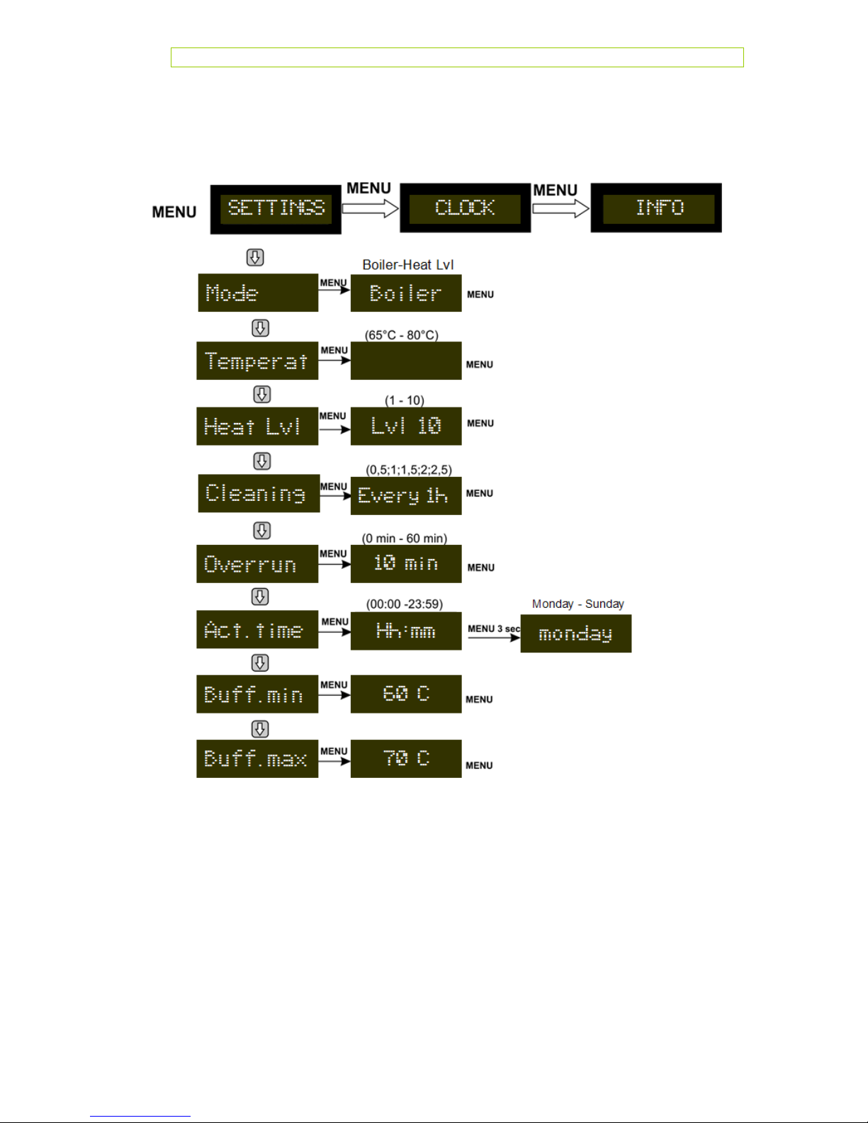
5.3 Menu settings ....................................................................................................... 21
5.3.1 Boiler operations ............................................................................................... 22
5.3.2 Level operation ................................................................................................. 22
5.3.3 Boiler temperature set ....................................................................................... 22
5.3.4 Setting fixed level.............................................................................................. 22
5.3.5 Cleaning interval (small cleaning) ........................................................................ 23
5.3.1 Overrun-Nachlauf (external request).................................................................... 23
5.3.2 Setting the current time ..................................................................................... 24
5.3.3 Setting the Buffer MIN. temperature (Buffer tank lower level) ................................. 24
5.3.4 Setting the Buffer MAX. temperature (Buffer tank upper level) ................................ 24
5.4 Clock menu item ................................................................................................... 25
5.4.1 Clock function (UHR-FUNKT) ............................................................................... 25
5.4.2 Monday to Friday program (Mon-Fri) .................................................................... 26

PELLING ECO
4
5.4.3 Saturday program (SAT-SUN) ............................................................................. 26
5.4.4 Create time program ......................................................................................... 26
5.5 Menu item INFO ................................................................................................... 27
5.5.1 State ............................................................................................................... 27
5.5.2 Stage ............................................................................................................... 28
5.5.3 Boiler °C .......................................................................................................... 28
5.5.4 Buffer ( visible only when buffer probes are conected) ........................................... 28
5.5.5 Flame °C .......................................................................................................... 28
5.5.6 Preasure .......................................................................................................... 28
5.5.7 Ext Device ........................................................................................................ 28
5.5.8 Fan RPM ........................................................................................................... 28
5.5.9 Ignitor ............................................................................................................. 29
5.5.10 Insert ........................................................................................................... 29
5.5.11 Pump ........................................................................................................... 29
5.5.12 Software ....................................................................................................... 29
5.5.13 Operating hours ............................................................................................. 29
5.6 Language ............................................................................................................. 29
5.7 Time setting ......................................................................................................... 29
5.8 Parameter setting ................................................................................................. 30
6 Cleaning and maintenance ...................................................... 31
6.1 Every 1 – 10 days cleaning the firebox (depends of pellets quality) ............................. 32
6.2 Cleaning the combustion chamber and ash tray ........................................................ 32
6.3 Every 4-7 days cleaning the tube exchanger ............................................................ 33
6.4 Every six months .................................................................................................. 34
6.4.1 Cleaning the flue gas exhaust chamber ................................................................ 34
7 Boiler assembly and commissioning ........................................ 35
7.1 Conditions ........................................................................................................... 35
7.2 Flue gas pipes ...................................................................................................... 35
7.3 Minimum distances to be respected between the boiler and the objects and walls ......... 37
7.4 Hidraulic connection diagrams ................................................................................ 38
8 Electrical connection ............................................................... 41
8.1.1 Power supply .................................................................................................... 41
8.1.2 Pump output ..................................................................................................... 41
8.1.3 Ext request (room thermostat) ............................................................................ 41
8.1.4 Function explanation buffer tank sensor ............................................................... 42
8.2 Boiler internal wiring ............................................................................................. 42
9 Saffety devices and security .................................................... 44
10 Troubleshooting ................................................................... 45
10.1 Safety temperature breaker (STB) .......................................................................... 46

PELLING ECO
5
11 Notes on dismantling and disposal ....................................... 47
12 Guarantee ............................................................................ 48
12.1 Guarantee period .................................................................................................. 48
12.2 Guarantee conditions ............................................................................................ 48
12.3 Exclusions from the guarantee ............................................................................... 48
13 Wood burning Pelling ECO .................................................... 49
13.1 The process for firing wood .................................................................................... 51
14 EU Label ............................................................................... 52

PELLING ECO
6
2 Notes on the manual
2.1 Introduction
2.1.1 Ea sy an d saf e oper ation
This manual contains important information for proper and safe operation of the Pelling
boilers. Following these instructions you will avoid danger and repair costs, and also
increase the operational life of the boiler.
2.1.2 Re ading the m anua l
This manual must be read and applied by everyone who operates or works on the Pelling
boiler.
2.1.3 Te chnic a l cha nges
ThermoFLUX continuously develops and improves its boilers. The information in this
version is correct at the time of going to press. All details in this manual on standards
and regulations should be checked before use and should be compared with the installed
boiler. We reserve the right to make changes which may then deviate from the technical
details and illustrations in this manual.
2.1.4 Co pyrig ht
Written agreement is required from Thermo FLUX d.o.o. for any reprints, storage in
a data–processing system or transmission by electronic, mechanical or any other
means, for copies and publications, in whole or in part.

PELLING ECO
7
2.2 Structure of the Use and maintenance manual
The use and maintenance manual is structured as follows:
Chapter
Here you can see
Notes on the manual
How to use this Use and maintenance
manual.
Safety notes
Everything on the subject of safety.
Functional description
The structure and all the features of the
boiler.
Using the boiler
How to properly operate the boiler.
Cleaning and maintenance
How you can clean the boiler and who is
responsible for its maintenance.
Commissioning
How to put the boiler initially into operation.
Troubleshooting
How you can remedy possible faults.
Notes on dismantling and
disposal
What has to be considered before disposing
of the boiler.
Guarantee
What the conditions of the guarantee are.
Table 1 Structure of the Use and maintenance manual

8
3 Safety notes
3.1 Proper use
3.1.1 Ba sic p r inci p les f o r th e con s t ruct i on of the
syste m
Basic principles
Pelling boiler was built using advanced technologies and it is in accordance with safety
regulations. However, its use can result in the injury or death of of the user and/or third
part and in impairments to the boiler itself or to other material goods.
Using the boiler
Use the boiler only when it is in perfect condition. Use it properly, as described in this
manual. Stay aware of the safety and of the dangers involved. Have any faults which can
impair safety immediately fixed.
3.1.2 Re liabl e and unrel iable m od es of opera t ion
Use of the boiler
The boiler was designed to burn wood pellet and wood. The manufacturer will accept no
responsibility for any damage resulting from improper use. Proper use includes
maintaining the installation, operation and maintenance specified by the manufacturer.
The user may only enter or change the operating values specified in this manual. Any
other entries will affect the boiler's control programme and operation, which can lead to a
malfunction.
PELLING ECO
9
3.1.3 Pe r miss ible fuel f or th e Pell in g boil ers
Only wood pellets and wood are permissible as fuel for the boiler. Wood pellets are
pressed into a cylindrical shape. They consist of untreated sawdust from the wood
processing industry as well as unprocessed forestry waste. They have a standardised
diameter and length and very low water content.
Recommended wood pellets
Thermo FLUX d.o.o. recommends wood pellets with a diameter of 6 mm and a length
of 10 - 30 mm. Other requirements on the fuel result from either standard Standards
PELET C1 from EN 303-5:2012 Tabele 7 ; Water content less 12 % and DIN 5137
und ÖNORM 7135.
Pay particular attention to the wood pellet quality.
3.2 Residual risks
Despite all precautions, the following residual risks remain:
DANGER OF ASPHYXIATION DUE TO CARBON MONOXIDE If the
boiler is operating during the cleaning time, carbon monoxide can
be emitted through the open boiler door. Do not leave the boiler
door open any longer than necessary.
CAUTION ! Hot surface. Contact with the hot surface of the boiler
can lead to burns. Wait until the boiler has cooled down before
touching uninsulated components.

PELLING ECO
10
3.3 Warnings and safety symbols used
The following warnings and safety symbols are used in this Use and
maintenance manual.
DANGER OF ELECTRIC SHOCK. Work on areas
marked with this symbol may only be done by a
qualified electrician.
WARNING! Warning about a dangerous location.
Work on areas marked with this symbol can lead to
serious injuries or to extensive material damage.
CAUTION! Hand injuries. Work on locations marked
with this symbol can lead to hand injuries.
CAUTION! Hot surface. Work on locations marked
with this symbol can lead to burns.
CAUTION! Danger of fire. Work on locations marked
with this symbol can lead to a fire.
CAUTION! Frost danger. Work on locations marked
with this symbol can lead to frost damage.
Notes on disposal.

PELLING ECO
11
3.4 Duty to inform
Reading the manual
Everyone who works on the boiler must have read the Use and maintenance manual
before starting work and, in particular, have read the second chapter „Safety notes“. This
holds especially true for persons who only occasionally work on the boiler e.g. when
cleaning or maintaining the boiler. This manual must be kept ready to hand at the
boiler's installation location.
Pay particular attention to the applicable local standards and
guidelines.

12
4 Functional description
Accompanying material
– brush for the pipeline cleaning and a blade
– instructions booklet
PELLING ECO
13
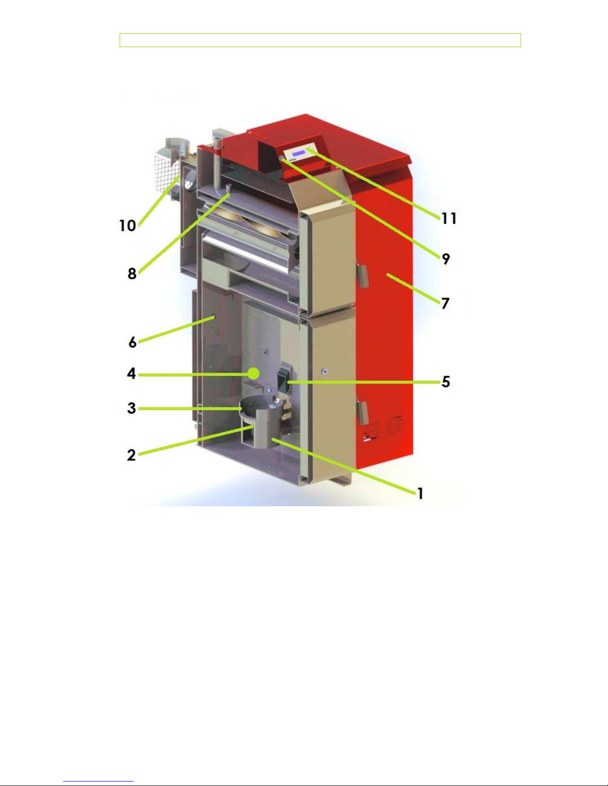
4.1 Basic operating principle
1. Combustion basket holder
2. Heater
3. Combustion basket
4. Combustion chamber
5. Dispenser
6. Falme temperature sensor
7. Pellets silo
8. Boiler temperature sensor and
STB temperature sensor
9. Safety limiter Thermostat STB
10. Exhaust fan
11.Control unit
PELLING ECO
14
In the Pelling boiler the pellets introduced into the combustion burner. are automatically
ignited with an electric heater. Burnt pellet (ash) is collected in the ash pan. which is placed
under the combustion burner. The air necessary for combustion is supplied to the
combustion burner.
Through sensors:
1. The boiler power is adjusted to the heat requirement.
2. The boiler efficiency is optimised.
3. Flue gases are optimised.
The boiler is not intended for condensing way of working.
PELLING ECO
15
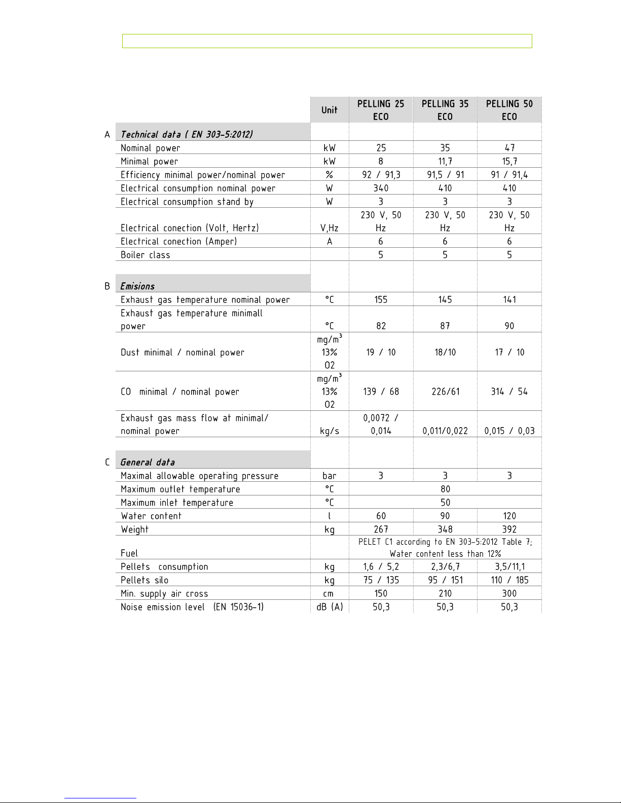
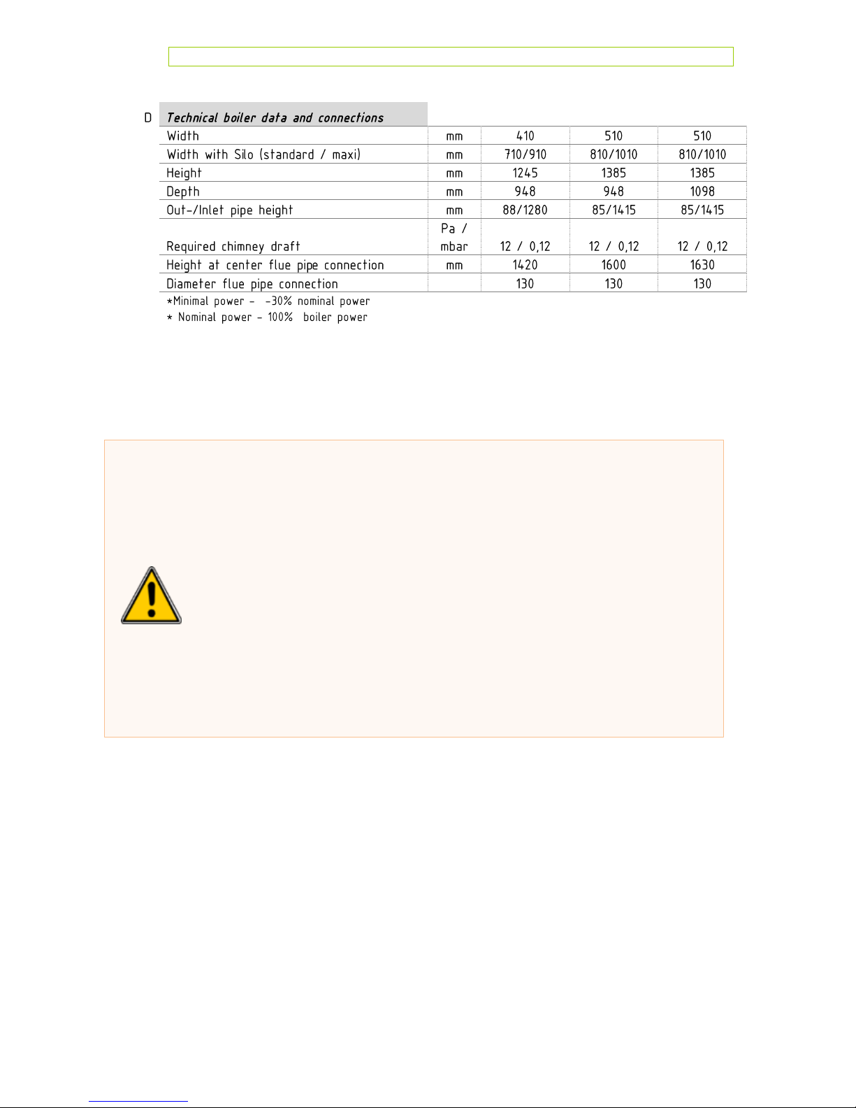
4.2 Technical data
²
PELLING ECO
16
Ø
During assembly and installation of the boiler, the regulations and
laws rules of the state in which the boiler is installed must be
considered.
The assembly and installation can only be performed by qualified
personnel.
The heating installation must be calculated by professionally.
The Schronstein and the exhaust pipes must expects professionally
built and placed the law directives.
Storing pellets dry.
In certain countries, the emissions shall be measured after the
commissioning of the furnace.
PELLING ECO
17
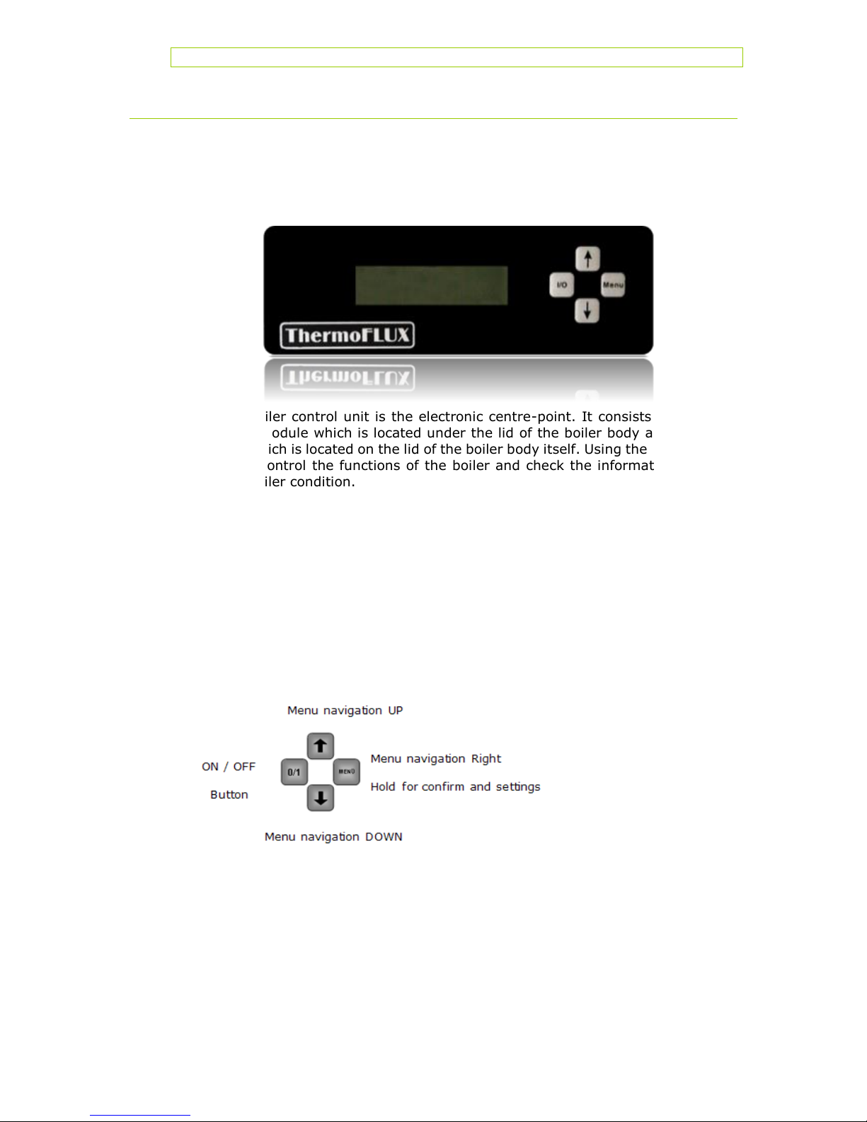
5 Using the boiler
The Pelling boiler control unit is the electronic centre-point. It consists of the
main control module which is located under the lid of the boiler body and the
control unit which is located on the lid of the boiler body itself. Using the control
unit you can control the functions of the boiler and check the information on
the current boiler condition.
Pelling boiler responds to demands of the central system and can easily meet
the need to increase the power due to five different operation strengths and
automatic switching. If there is a need to increase the power, the regulation
system automatically increases the operation strength which leads to increased
dosage of pellets and, proportionately, increased amount of the blown air in the
combustion chamber.
Once the desired boiler temperature has been reached (the need for heat has
been met) than the regulation reduces the operation strength.
PELLING ECO
18
 Loading...