

ThermoFLUX PELLING 18, PELLING 25, PELLING 35, PELLING 75, PELLING 100 User And Maintenance Manual
...
ThermoFLUX d.o.o., Bage br. 3, 70101 Jajce, Bosna i Hercegovina, Tel/Fax: 030–657-100
www.thermoflux.ba tfinfo@thermoflux.ba
PELLET BOILER
USER AND MAINTENANCE MANUAL
2

PELLING
3
Content:
1 Notes on the manual .................................................................... 5
1.1 Introduction ....................................................................................................... 5
1.1.1 Easy and safe operation .................................................................................... 5
1.1.2 Reading the manual ......................................................................................... 5
1.1.3 Technical changes ............................................................................................ 5
1.1.4 Copyright ....................................................................................................... 5
2 Safety notes ................................................................................ 6
2.1 Proper use ......................................................................................................... 6
2.1.1 Using the boiler ............................................................................................... 6
2.1.2 Permissible fuel for the Pelling boilers ................................................................. 7
2.1.3 Safety instructions for boiler room ...................................................................... 7
2.1.4 Fresh air supply ............................................................................................... 7
2.2 Warnings and safety symbols used......................................................................... 8
2.3 Other risks of the side effects ................................................................................ 8
2.4 Obligatory informing ............................................................................................ 9
2.5 Safety devices .................................................................................................... 9
3 Functional description ................................................................. 10
3.1 General overview .............................................................................................. 10
3.2 Pellet boiler PELLING ......................................................................................... 11
3.3 Technical data .................................................................................................. 12
4 Function of boiler ....................................................................... 13
4.1 Overview of the controls and display and their basic functions .................................. 13
4.2 Principle of boiler operation ................................................................................ 15
4.2.1 How to lock the Display .................................................................................. 15
4.3 Schematic representation of the menu control ....................................................... 16
4.3.1 Clock adjustments ......................................................................................... 18
4.3.2 Adjustments of the programmed on and off mode ............................................... 19
4.3.3 LANGUAGE OPTIONS ...................................................................................... 21
4.3.4 STAND BY mode ........................................................................................... 21
4.3.4.1 STAND BY mode with installed sensor for water temperature ............................. 21
4.3.4.2 STAND BY mode with room thermostat connected ............................................ 22
4.3.5 Option Buzzer ............................................................................................... 22
4.3.6 Filling of spiral dispenser ................................................................................. 23
4.3.7 State of the boiler .......................................................................................... 23
4.3.8 Technical settings .......................................................................................... 23
4.3.9 FUEL TYPE .................................................................................................... 23

PELLING
4
5 Ignition and shutting down of boiler ............................................. 24
5.1 Ignition ........................................................................................................... 24
5.2 Shutting down of boiler ...................................................................................... 25
5.3 Boiler power adjustments ................................................................................... 25
5.4 Adjustment of water temperature in boiler ............................................................ 26
5.5 Modulation ....................................................................................................... 26
5.6 Cleaning of FIRE-POT......................................................................................... 27
5.7 Burning of wood ............................................................................................... 28
6 Cleaning and maintenance .......................................................... 30
6.1 Daily cleaning ................................................................................................... 30
6.2 Weekly cleaning ................................................................................................ 31
6.3 Monthly cleaning ............................................................................................... 32
6.4 Cleaning flue gas temperature sensor ................................................................... 33
7 Installation ................................................................................ 34
7.1 Conditions for installation ................................................................................... 34
7.2 Chimney and pipes for flue gas............................................................................ 34
8 Connection options ..................................................................... 37
8.1 Hydraulic schemes for connection ........................................................................ 37
8.2 Scheme for electric connection ............................................................................ 41
8.2.1 Control unit .................................................................................................. 42
9 Alarms ...................................................................................... 44
10 Instruction about safety removal and proper disposal of boiler ...... 45
10.1 Disposal .......................................................................................................... 45
11 Guarantee .............................................................................. 46
11.1 Guarantee period .............................................................................................. 46
11.2 Guarantee terms ............................................................................................... 46
11.3 Exemption from the guarantee ............................................................................ 46
12 EU Label.................................................................................... 47

PELLING
5
1 Notes on the manual
1.1 Introduction
Eas y a nd safe o pera ti on
This manual contains important information for proper and safe operation of the Pelling
boilers. Following these instructions you will avoid danger and repair costs, and also
increase the operational life of the boiler.
Reading the ma nua l
This manual must be read and applied by everyone who operates or works on the
Pelling boiler.
Techn ical c han ges
ThermoFLUX continuously develops and improves its boilers. The information in this
version is correct at the time of going to press.
All details in this manual on standards and regulations should be checked before use
and should be compared with the installed boiler.
We reserve the right to make changes which may then deviate from the technical
details and illustrations in this manual.
Cop yright
Written agreement is required from Thermo FLUX d.o.o. for any reprints, storage in a
data–processing system or transmission by electronic, mechanical or any other means,
for copies and publications, in whole or in part.
NOTE: Please save the received documents. In the event of a malfunction,
service personnel need a serial number and the year of manufacture of the
boiler, without these basic info we can not acknowledge a malfunction or
service it.

PELLING
6
2 Safety notes
2.1 Proper use
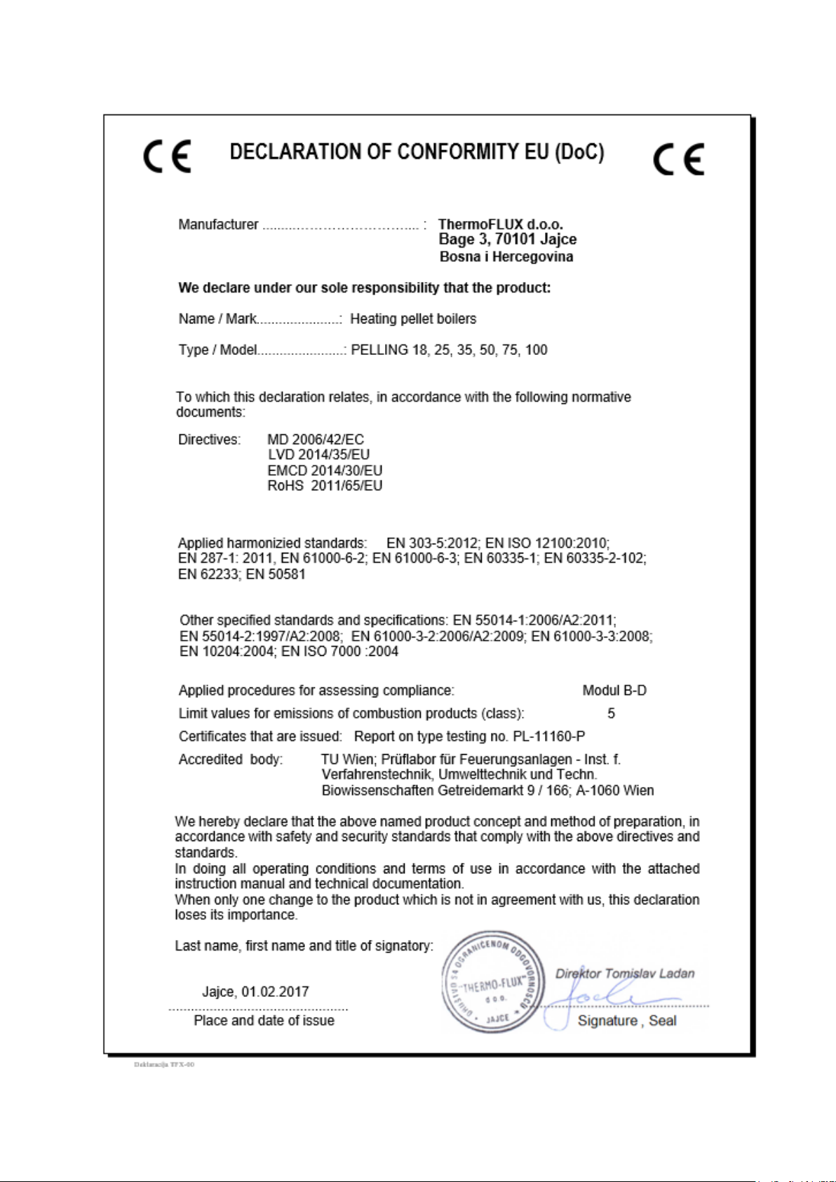
Pelling boiler was designed and built in accordance with safety regulations:
UNI EN 303-5 Heating boilers, Heating boilers for solid fuels, manually and
automatically stoked, nominal heat output of up to 500kW
73/23/EEC Low Voltage Electrical Equipment
89/336/EEC Electromagnetic Compatibility (EMC), EU Council Directive
However, its use can result in the injury or death of the user and/or third part and in
impairments to the boiler itself or to other material goods.
The boiler was designed to burn wood pellet and wood. The manufacturer will
accept no responsibility for any damage resulting from improper use. Proper
use includes maintaining the installation, operation and maintenance
specified by the manufacturer. The user may only enter or change the
operating values specified in this manual. Any other entries will affect the
boiler's control program and operation, which can lead to a malfunction.
Usi ng the bo ile r
Use the boiler only when it is in perfect condition. Use it properly, as described in this
manual. Use the boiler as described in this manual. Get to know security measures
and possible hazards. Remove any faults that could affect the safety. The operation of
a faulty boiler can cause fier or explosion.
The boiler is intended for combustion of wood pellets and wood. Any other use is
incorrect. It is forbidden to burn any other fuel other than pellets and wood. The
manufacturer will not assume responsibility for any damage caused by improper
handling. Correct use implies maintenance of the installed boiler, operation and
maintenance conditions prescribed by the manufacturer.
The user can enter or change only the values specified in this manual. Any
other value of the parameters will affect the control program, and the
operation od the boiler, wich can ultimately lead to the termination of the
correct operation. In that case, the boiler is not subject to warranty anymore.
PELLING
7
Permissible fue l f or the Pe lling boi le rs
The boiler is designed for burning wood pellets with a diameter of 6mm and a length
of 10-30mm. In exceptional cases, by inserting additional grid as an alternative can
also be used dry wood. We do not recommend a continuously burning of wood for
more than 30 days.
The pellets quality is derived from the EN 303-5: 2012 Standard (Table 7. Water
content les than 12% according to DIN 51731-HP5, DINplus certification program and
ÖNORM M7135-HP1 or ENPlus-UNI EN 14961-2, UNI EN ISO 17225-2 class A1 or A2.
6mm diameter, length 10-30mm)
Particular attention should be paid to the quality of wood pellets. Low-grade
pellets can cause malfunction of the boiler.
Safe ty in struct ion s f or boil er room
The boiler room must be made according to current regulations, especially regarding
fire protection. No flammable material should be stored in the boiler room.
The room where the boiler is installed must be frost-resistant.
The boiler should not be exposed to cold or freezing temperatures. Extreme cold
temperatures can cause mailfunction and unexpected behavior of electronic
components.
Fresh air su pply
For combustion of pellets and normal work boiler needs fresh air. The room in wich the
boiler is installed must have an opening for fresh air supply. The recommended
minimum dimension is 30x15cm.
PELLING
8
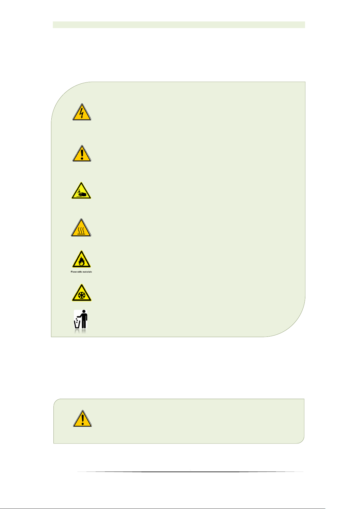
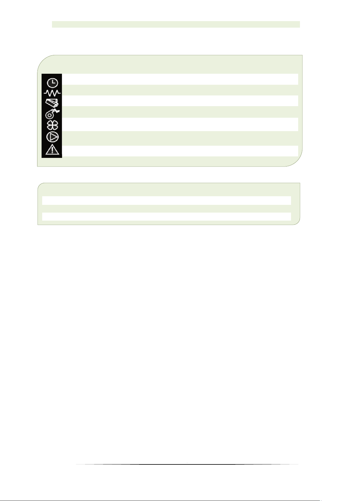
2.2 Warnings and safety symbols used
2.3 Other risks of the side effects
Despite the precautions taken there are also certain risks of side effects:
DANGER OF CARBON MONOXIDE.
If the boiler is running during cleaning time may occur
transmission of CO through the open door. Do not open
the door longer than necessary.
DANGER OF ELECTRIC SHOCK.
Work on areas marked with this symbol may only be done by
a qualified electrician.
WARNING!
Warning about a dangerous location. Work on areas marked
with this symbol can lead to serious injuries or to extensive
material damage.
CAUTION!
Hand injuries. Work on locations marked with this symbol can
lead to hand injuries.
CAUTION!
Hot surface. Work on locations marked with this symbol can
lead to burns.
CAUTION!
Danger of fire. Work on locations marked with this symbol can
lead to a fire.
CAUTION!
Frost danger. Work on locations marked with this symbol can
lead to frost damage.
Instructions for proper disposal of waste.

PELLING
9
2.4 Obligatory informing
Everyone who operates with the boiler must read the instructions before using it, in
particular, the chapter ’’Safety Instructions’’.
This applies especially to persons who occasionally work on a boiler, for example,
cleaning and maintaining boilers. This manual should always be kept near the installed
boiler.
Pay particular attention to the applicable local standards and guidelines. All
local laws must be respected during installation, as well as standards and
norms that are in force in the country where the boiler is installed even
though it is not listed in this manual.
The Installation can be carried out only by persons (service technicians) who
are trained/educated and have a license for this job.
The central heating system must be properly calculated and dimensioned.
The chimney should be calculated and made according to EN 13384-1. The
chimney must be thermally insulated to prevent condensation.
Storage of pellets can be done only in places that are dry and free from
moisture.
In certain countries, it is necessary to measure the emissions of gases by an
authorized person during the first commissioning.
2.5 Safety devices
Boiler is equiped with safety devices that in case of unexpected situations
stop the power supply and thereby stop the operation boiler.
Microprocessor control on the boiler: Intervenes directly, turns off the boiler until
it cools down and shows an error on the display screen in case of a fan failure, failure
of the motor for auger, or the ignition.
Fuse F4A 250V: Fast fuse, protects the boiler from large voltage changes of electricity
and short circuits inside the boiler.
Safety limiting thermostat (STB): intervenes by breaking the circuit in the boiler
(automatically stops motor of the auger and exhaust gasses fan) if the boiler
temperature reaches the limit of 95°C.
Vacuum switch: intervenes in case of low underpressure in burnerroom(open door,
chimney jammed).
PELLING
10
3 Functional description
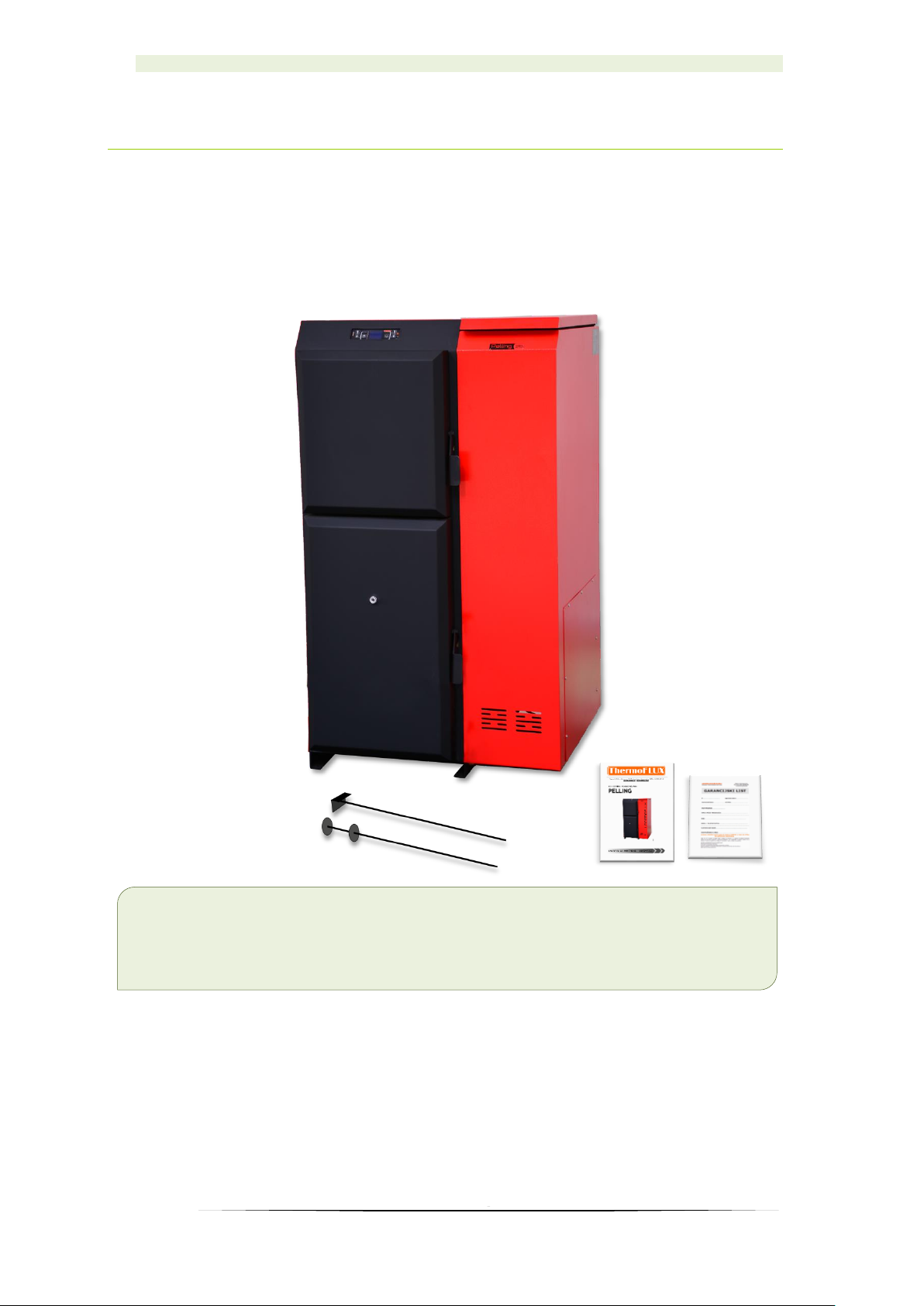
3.1 General overview
Accompanying material
Tools for the pipeline and firebox cleaning
Instructions booklet
Guarantee
PELLING
11
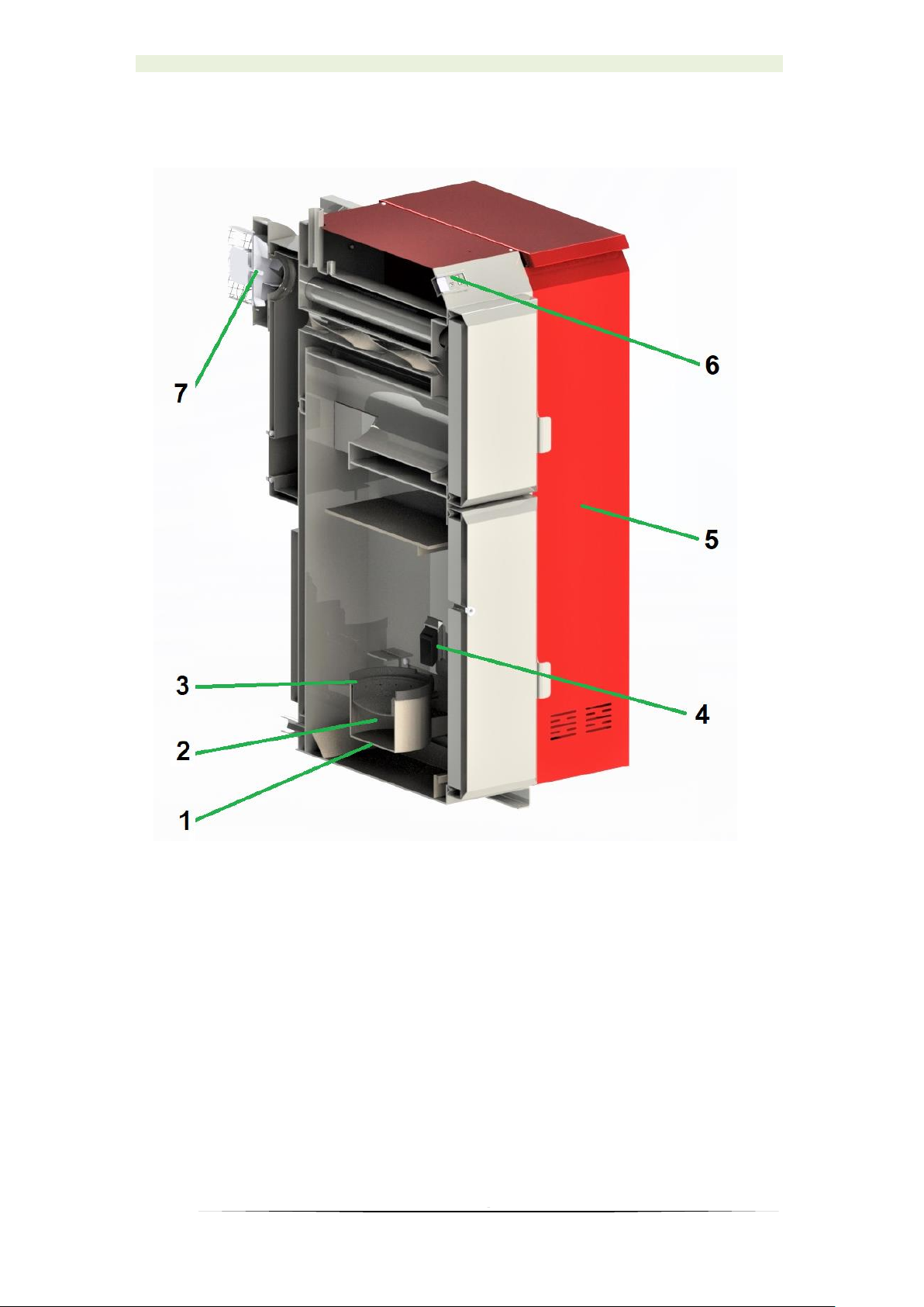
3.2 Pellet boiler PELLING
1. Combustion burner
2. Heater
3. Combustion chamber
4. Dispenser
5. Silo
6. Control unit
7. Exhaust fan
In the Pelling boiler the pellets introduced into the combustion burner 1. They are
automatically ignited with an electric heater 4. Burnt pellet (ash) is collected in the ash
pan 3. which is placed under the combustion burner. The air necessary for combustion
is supplied to the combustion burner.
The boiler power is aligned to the requirements of the cetral heating system.
The usability and efficiency of the boiler is pre-optimized.
PELLING
12
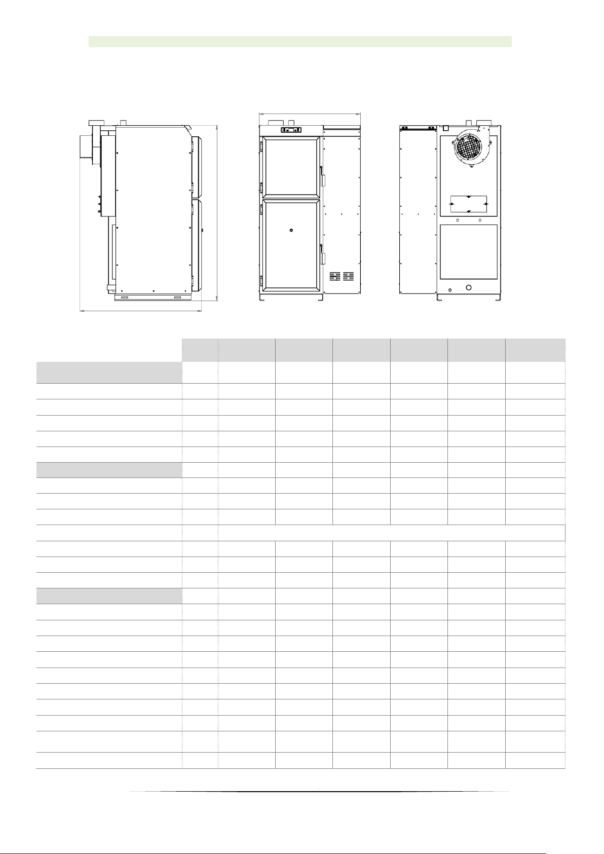
3.3 Technical data
Pelling
18
Pelling
25
Pelling
35
Pelling
50
Pelling
75
Pelling
100
Performance (measured
according to EN 303-5: 2012)
Maximum power
kW
18
25
35
50
75
100
Minimum power
kW 6 8
11,7
16,5
25
33
Power supply
V,Hz
230V,50 Hz
230V, 50 Hz
230V, 50Hz
230V, 50Hz
230V, 50 Hz
230V, 50 Hz
Electrical conection (current)
A 6 6
6
6
6
6
Boiler class
5
5
5
5
5
5
General information
Max. Permited presure
bar
2,5
2,5
2,5
2,5
2,5
2,5
Max. Permited temperature
°C
80
80
80
80
80
80
Min. permited return temperature
°C
50
50
50
50
50
50
Fuel
EN PLUS - UNI EN 14961 - 2 (UNI EN ISO 17225-2) Class A1/A2
Pellet consumption (min/max)
kg/h
1,3/3,9
1,6/5,2
2,3/6,7
3,5/11,1
5,2/16,6
6,5/22,2
Pellet storage capacity
kg
75
75/135
95/151
110/185
270
290
Minimal fresh air opening
cm
30x15
30x15
30x15
30x15
30x15
30x15
Technical data
Boiler width
mm
410
410
510
510
560
650
Boiler width with pellet storage
mm
710
710/910
810/1010
810/1010
1060
1150
Height
mm
1245
1245
1385
1385
1670
1650
Depth
mm
798
948
948
1098
1240
1240
Water content
l
48
60
90
120
154
181
Weight
kg
197
267
348
392
494
580
Height out/return
mm
1280/88
1280/88
1415/85
1415/85
1568/70
1532/75
Minimal chimney underpresure
Pa 5 5
5
5
5
5
Flue gas pipe height
(direction UP)
mm
1420
1420
1440
1440
1598
1630
Flue gas pipe diameter
Ø
120
120
120
120
150
150
*minimal power-30% maximum power
PELLING
13
4 Function of boiler
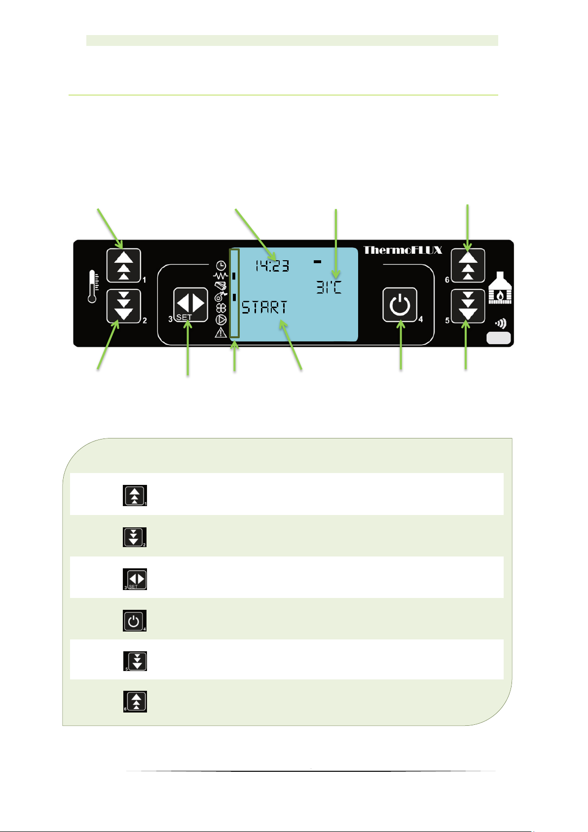
4.1 Overview of the controls and display
and their basic functions
Button
Description
1 -
Increasing temperature and program functions
(adjusting days, time...)
2 -
Decreasing temperature and program functions
(adjusting days, time...)
3 -
Changing – accepting program
4 -
ON / OFF, program exit
5 -
Decreasing power, navigate through the menu
6 -
Increasing power navigate through the menu
1
23 4 5 6 7 8 910
PELLING
14
Display
8
Info
9
Clock
10
Water temperature indicator
Regulation on the boilers ''Pelling'' is most important electronic component. It is
consisted of key controling modul set under the cover of the boiler and controling unit
with display set on the front side of the boiler. With controling unit it is possible to
control functions of the boiler and also to check information about present state of the
boiler.
Due to the possibilty to work in 5 (five) different powers, regulation can satisfy needs
to increase or decrease heating by automatic adjustment of power.
If there is a need to increase power, this is registered by regulation and regulation
gives a signal to increase power by adding more pellet as well as proportional increase
of air flow in the burning basket.
When desired temperature is reached (need for heating energy is satisfied) regulation
is decreasing power ( modulates ), or when room thermostat gives signal that set
temperature is reached, boiler then goes into shut down (if mode STAND-BY is ON).
7
When mark is visible
Clock
programmed ignit. active
Heater
heater active
Pelet dosage
auger active
Smoke fan
fan active
Primary air fan
fan active
Circulating pump
pump active
Alarm
alarm active
7
PELLING
15
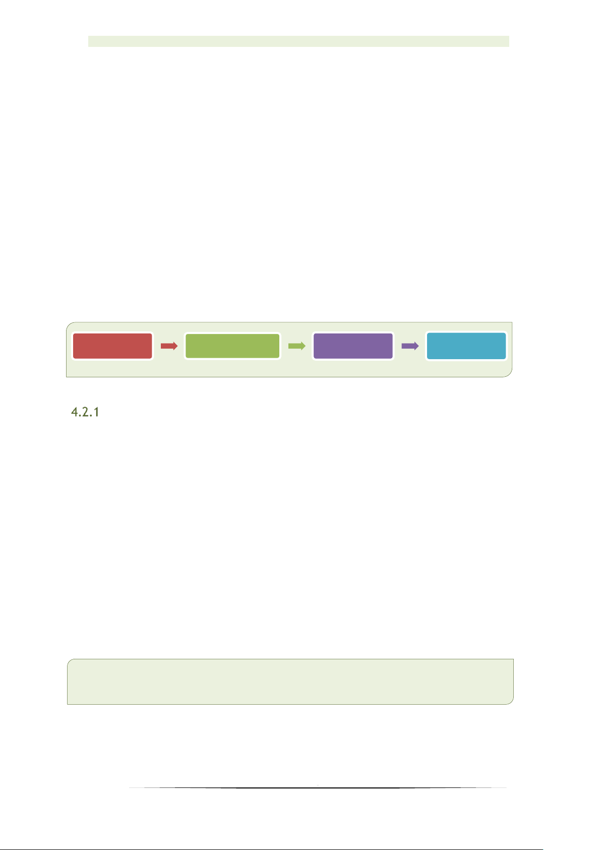
4.2 Principle of boiler operation
Principle of the boiler operation is very simple.
When button for start is pressed boiler goes into IGNITION MODE. START is
displayed, and after that PELLET IGNITION. Usually this phase lasts for 5-15 minutes
depending on type of the boiler and pellet quality. At that point dosing system is
activated, igniter and suction fan. Dispenser is making initial dosing of pellet into
burning basket. At the same point igniter starts to ignite pellet and suction fan is on
and is making necessary underpressure needed for combustion. When temperature
sensor for flue gasses detects that temperature in the chimney has reached necessary
value, regulation then changes working mode of the boiler into FLAME
STABILIZATION.
This phase (FLAME STABILIZATION) lasts for 2-3 minutes (depending on the type
of the boiler) and in this phase igniter goes off. After flame stabilization, boiler goes
into the normal working mode and changes power from power 1 to set power. On
display is written WORK. On the right side set power is displayed and in the last
How to loc k the Display
Press the SET button (key 3) and select from the menu:
M-8 TECHNICAL SETTINGS.
With the (up) arrow (key 1) go to A9 (A9 is found when it exceeds 99). Press
SET, and then go with the (down) arrow (key 5) and select:
M-8-4 GENERAL SETTINGS.
Then, with the (down) arrow select:
M-8-4-10 FROZEN KEYBOARD.
Turn ON and confirm with SET.
Return to the main menu by pressing ON/OFF (key 4).
We lock and unlock the display as follows:
Press the SET button (key 3) and then the ON/OFF button (key 4).
Start
PELLET IGN.
Flame
stabilization
WORK
 Loading...