

ThermoFLUX ENplus-A1, ENplus-A2, EN-B Installation And Operation Manual
TECHNICAL PASSPORT INSTALLATION and OPERATION MANUAL
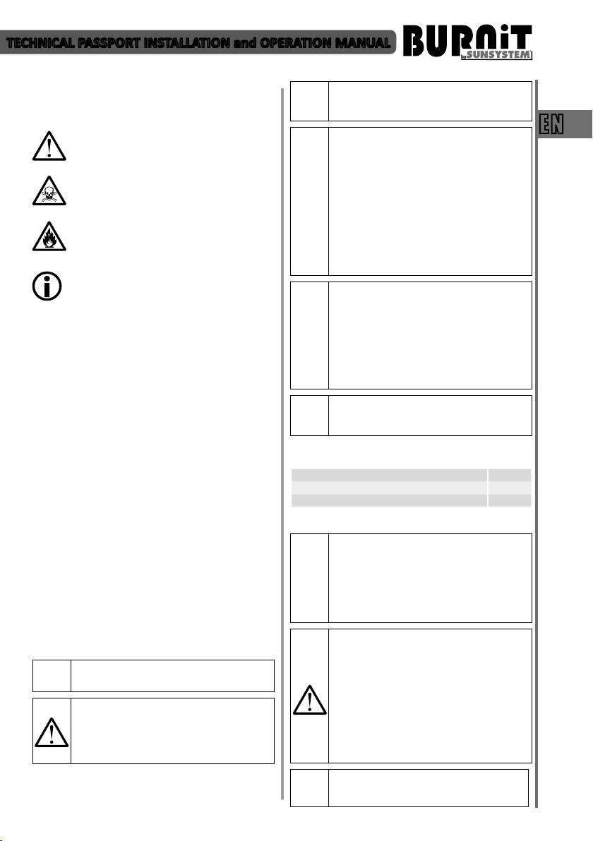
Pellet burning boiler BioFlux series
EN
TECHNISCHES DATENBLATT MONTAGE- und BEDIENUNGSANLEITUNG
Pelletkessel Serie BioFlux
MANUEL TECHNIQUE INSTRUCTIONS pour L’INSTALLATION et L’EXPLOITATION
Chaudière à granulés de bois série BioFlux
DE
FR
model:
serial number:
Version p0.8.1

TECHNICAL PASSPORT INSTALLATION and OPERATION MANUAL
Table of contents
1. EXPLANATION OF SYMBOLS AND SAFETY INSTRUCTIONS ..................................................................... 3
EN
1.1. Explanation of symbols .......................................................................................................................... 3
1.2. Requirements to boiler installation room .............................................................................................. 3
1.2.1. Instructions to boiler installer ................................................................................................................. 3
1.2.2. Instructions to installation user ............................................................................................................. 3
1.2.3. Minimum clearances for installation. Combustibility of construction materials ................................... 4
2. PRODUCT DESCRIPTION ......................................................................................................................... 4
3. FUELS ..................................................................................................................................................... 6
4. TRANSPORTATION .................................................................................................................................. 7
5. DELIVERY OF THE BOILER ................................................................................................................... 7
6. INSTALLATION OF THE HEATING BOILER ................................................................................................ 8
7. SETUP OF THE HEATING BOILER ............................................................................................................. 8
7.1. Connecng the boiler to a chimney ....................................................................................................... 8
7.2. Pellet boiler connecon to the pellet burner, auger and fuel hopper ................................................... 8
7.3. Connecng the boiler to the mains power supply .................................................................................. 9
7.4. Connecting the boiler to the heating installation ................................................................................... 9
7.5. Connection diagrams ............................................................................................................................ 11
8. FILLING THE HEATING INSTALLATION ................................................................................................ 11
9. OPERATION OF BOILER ...................................................................................................................... 11
10. CONTROLLER UNIT ............................................................................................................................... 14
10.1. Controller view. Explanation of buttons and indicators ....................................................................... 14
10.2. User menu ............................................................................................................................................ 16
11. MOUNTING OF FUEL HOPPER FH 500 .................................................................................................. 17
12. WARRANTY TERMS .............................................................................................................................. 17
13. TECHNICAL FEATURES .......................................................................................................................... 17
13.1. Technical features of PelleBurn pellet boiler ........................................................................................ 17
13.2. Technical parameters of Pell pellet burner ........................................................................................... 18
13.3. Technical features of fuel hoper FH 500 ............................................................................................... 19
14. RECYCLING ............................................................................................................................................ 20
APPENDIX - DIAGRAMS ........................................................................................................................ 59
2
TECHNICAL PASSPORT INSTALLATION and OPERATION MANUAL
1. EXPLANATION OF SYMBOLS AND SAFETY
1.1. Explanation of symbols
CAUTION! - Important recommendation or
warning concerning safety conditions during
installation and operation of boiler.
DANGER! - fault or improper use may cause
injury or be hazardous to life of humans or
animals.
FIRE HAZARD! - fault or improper installation
and operation may cause fire.
INFORMATION – Important information on
the proper operation of the product.
1.2. Requirements to boiler installation room
This manual contains important information for the
safe and correct installation, start-up and troublefree operation and maintenance of the boiler.
The Pellet boiler can be used for heating rooms only
in the manner described in this manual.
The application and any other was the area of
operation is not recommended by the manufacturer
and is not responsible for the occurrence of defects
or failures.
Note the boiler type data on the factory rating label
and the technical data provided in chapter 13 in
order to ensure proper operation of the product.
1.2.1. Instructions to boiler installer
During installation and operation, the country-
specific requirements and regulations must be
observed:
• Local construction regulations on installation,
air supply and exhaust gas extraction as well as
chimney connection.
• Regulations and norms concerning the fitting of the
heating installation with safety devices.
• Required installation of a smoke detector in the
boiler room.
Use only original BURNiT parts
i
WARNING! Installation and setup of the
boiler should be done by an authorized
specialist / service shop and must follow
the safety instructions and rules of
operation.
INSTRUCTIONS
It is mandatory to assure a backup power
generator of corresponding rated power!
(see table 1)
DANGER of intoxication, suffocation.
Inadequate inflow of fresh air to the
boiler room may result in dangerous leak
of exhaust gases during boiler operation.
- Make sure the air inlets and exhaust gas
outlets are not clogged or closed.
- If faults are not remedied immediately, the
!
1.2.2. Instructions to installation user
$
3
boiler must not be operated.
- The user must be provided with written
instructions on the fault and the hazard it
entails.
DANGER of fire when burning flammable
materials or liquids.
- Flammable materials/liquids must not be
left in close proximity of the burner and
heating boiler.
- Instruct system user of the allowed
minimum clearances from surrounding
objects.
Customer must undergo boiler operation/
maintenance training by authorized
installer/service shop.
Table 1.
Electricity consumpon of the boiler
Maximum electrical input 780 W
Electrical input at nominal heat output 80 W
Electrical input at minimum heat output 60 W
DANGER of intoxication or explosion
Toxic gases may be discharged when
burning waste, plastics, liquids.
- Use only the fuels indicated in this manual.
- In case of danger of explosion, ignition or
discharge of exhaust gases in the room,
stop the pellet burner from operation.
CAUTION! Danger of injury / damage of
system due to incompetent operation.
- The boiler must be serviced only by persons
familiar with the operation manual.
- As user, you are only allowed to start the
boiler up, adjust the temperature of the
boiler, shut the boiler down and clean it.
- Unattended children must not be allowed
access to premises with running boiler
inside.
It is mandatory to assure a backup power
generator of corresponding rated power!
(see table 1)
EN
TECHNICAL PASSPORT INSTALLATION and OPERATION MANUAL
Customer must undergo boiler operation/
maintenance training by authorized
installer/service shop.
EN
- Operate the pellet burner on recommended fuel
only, and to that end you must regularly inspect the
boiler room.
- Do not use flammable liquids for ignition or increase
of burner output.
- Clean the burner surface using non-flammable
agents only.
- Do not place flammable objects onto the burner
housing and heating boiler cabinet or in their
proximity. (see diagram 1 for the minimum
clearances)
- Do not store flammable materials in the boiler room.
- It is mandatory to strictly observe instructions for
connecting the burner to power network as well as
to all peripherals.
- Structural changes to Dual-chamber boiler by user
can cause damage to equipment or injury.
- Do not allow contact transmission of electrical wire
or touch any part of the boiler, where the surface
temperature can exceed 70°C.
- This manual should be kept throughout the lifetime
of the boiler.
1.2.3. Minimum clearances for installation and
flammability of construction materials
The applicable minimum clearances in your country
may differ from the ones specified below. Please,
consult your installer.
The minimum distance from the burner, heating
boiler or exhaust gas pipe to objects or walls must be
at least 200 mm.
Safety rules for user operation:
CAUTION! Hot surface!
Risk of burns if you touch the running
system. Burner housing, body and flange
are hot surfaces during burner operation.
It is strictly prohibited to open boiler
inspection doors with the burner running.
The hopper hatch cover is not allowed to
remain open for longer periods of time.
Also, exercise caution when touching the
observation port for monitoring the burning
process. It may be hot.
Table 2. Flammability of construction materials
Class А – non-
flammable
Class B – hardly
flammable
Class С1/
С2 – Medium
flammable
Class C3 – easy
flammable
For general safety considerations, we recommend
that the boiler be placed on a foundation made of
class A material, see table 2.
Diagram 1. Recommended clearances
between boiler and walls /see page 59/
Ecological and highly-efficient pellet boiler PelleBurn
is designed for firing wood pellets. The mantle fully
covers the combustion chamber. Efficiency rate
reaching 91%. Approved in accordance with EN 3035, class 5. Set includes pellet boiler, pellet burner,
auger and pellet fuel hopper (option).
2.1. Design structure of boiler PelleBurn.
Cylindrical body design is made of high-quality
boiler steel sheets with thickness of 4 mm for the
combustion chamber and 3 mm for the water mantle.
• Ecological. A high-end pellet boiler. The wood
pellets used for fueling the boiler are a renewable
fuel with minimum carbon emissions and ultimate
burning efficiency.
• Automated. Owing to an improved algorithm
with optional adjustment of a wide variety of
parameters, the system may befinely tuned to
any particular heating system to achieve optimum
efficiencyand fuel consumption.
1) fully automated ignion and pellet feed;
2) exhaust fan ensures stable operaon of the
boiler;
3) boiler-and-burner self-cleaning funcon;
4) controls the operaon of central heang
circulaon pump;
5) controls the operaon of DHW (domesc hot
water) pump;
6) controls by room thermostat;
7) ue gas sensor
4
Stone, bricks, ceramic tiles, baked
clay, solutions, plaster free of
organic additives.
Gypsum board panels, basalt fiber
needled felt, fiberglass board,
AKUMIN, Izomin, Rajolit, Lignos,
Velox, Heraklit.
Wood beech, oak. Wood softwood,
layered wood
Asphalt, cardboard, cellulose, tar,
fiberboard, cork, polyurethane,
polyethylene.
2. PRODUCT DESCRIPTION
Controller functions:
TECHNICAL PASSPORT INSTALLATION and OPERATION MANUAL
• Efficient. To keep from losing heat into the
ambience, the boiler is insulated on the outside
by 100 mm high-temperature wool. With its
state-of-the-art combustion control system
and cylindrical body design construction the
PelleBurn boiler achieves efficiency rate of as
much as 91%.
2.2. Design of pellet burner Pell
The burner is made of high-quality stainless steel
able to withstand temperatures of up to 1150°С. The
burner must be installed on a heating boiler.
The burner consists of two parts: combustion
chamber tube and external tube with sheet metal
mantle. Longitudinally, under the housing, there are
blow chamber, fuel ignition heater, fan and power
supply. On the upper part of the burner there is a
feeder chute to which the pellet auger is attached. The
combustion chamber consists of two tubes:
Ember resistant steel tube inside the burner with
holes for air intake along its entire length, opening
for the hot air from the fuel ignition heater, opening
for photosensor.
Outer stainless steel tube. Between the two tubes
there is a gap which provides for free circulation of
the air necessary both for cooling and oxygen supply
into the combustion chamber.
The feeder chute allows 360° rotation for its best
convenient positioning when connecting the pellet
auger to the hopper.
Diagram 2. Design of Pellet Burner Pell
/see page 59/
Other elements of the burner are
• Internal auger.
• Dry contactless resistance heater assuring ignion
of fuel.
• Pneumac cleaning system of the combuson
chamber.
• Feed fan, smooth regulaon (0% to 100 %).
• Telescopic pull-out system of burner Pell for easy
maintenance.
2.3. Safety devices of pellet boiler-and-burner
A complex of safety devices provide for the safety of
the appliance. Air-feed fan, step –regulated, controls
the combustion according to energy needs and is
maintained in optimal working order. Independent
STB thermostat shut-off the burner and shut off the
air feeding in the combustion chamber in case of
rising boiler temperature.
• Elbow-shape feeder chute. The geometrical shape
of burner feeder chute prevents backfire entry
from burner into pellet hopper. The flexible tube is
melted at a temperature above 80°C. Thus prevent
access to the hopper of the fire.
• Thermostatic protection (80°С). The thermostatic
protection is fitted on the feeder chute. When
the surface of the feeder chute reaches 80°С, the
control stops the feeding of pellets into the burner
and signals for fault (BB Alarm).
• Fuse. In case of electrical fault in the system of the
burner (short circuit, current overload, etc.), the
overload is borne by the electrical fuse fitted on the
main control panel of the burner (10 А).
• Power interruption. Innovative controller. In case
of power interruption, all parameter settings are
stored in the memory of the controller. Upon the
subsequent restart of the burner, the controller
resumes the execution of the program from the
point when the power interruption occurred.
2.4. Design of pellet auger
The auger transports pellets from fuel hopper to
burner. Auger elements are: auger pipe, auger hose,
motor, conveyor belt for moving the pellets.
D i a g ram 3 . D es ig n of pellet auger
/see page 59/
2.5. Design of fuel hopper FH 500
Pellet hopper, designated to serve biomass
pellet-fired boilers. Pellet hopper design allowing
installation by choice on either side of boiler.
Made of cold-rolled steel sheets with PVC coating.
Comfortable pellet charging hatch. Pellets inside
hopper are fed into auger in order of reception.
Precision leveling of hopper possible via screw-in legs.
Elevated foundation with drain holes and container
for separation and removal of pellet powder.
The hopper capacity is determined using as
calculation base the daily or weekly fuel consumption
rate of burner. The pellet hopper usable volume of
500 litters allows charging of 280-300 kg of pellets
with diameter 6 mm, and top-up/refill once a week
(for burner of rated power up to 40 kW).
Diagram 4. Design of fuel hopper FH 500
/see page 59/
5
EN

TECHNICAL PASSPORT INSTALLATION and OPERATION MANUAL
All pellets are biomass manufactured from common
3. FUEL
low-growing plants and trees. The most common
household type pellets are made of sawdust and
EN
milled wood chippings which are waste material
from wood used in the production of logs, furniture
and other products. Wood is the richest raw material
which does not have any impact on the production
costs of food products or ethyl alcohol (ethanol).
The raw material is processed under high-pressure
and temperature and is pressed to produce smallsize cylindrical pellets. The production process may
utilize soft wood material (such as softwood, pine),
hardwood (oak) as well as recycled waste wood.
Wood pellets are produced in hammer mills or wood
pellet plants.
Advantages of wood pellets:
Convenient storage.
Pellet bags can be stored on a small area in a dry
garage, basement, service room or shed.
Easy loading.
In most cases the boiler hopper needs loading only
once a week – this depends on the hopper capacity.
Better control of fuel quantity.
The small size of the pellets allows for precise fuel
feeding. On the other hand, the supply of air for
reaching optimal combustion efficiency is easier
to adjust since the fuel quantity in the combustion
chamber remains constant and predictable.
Fuel efficiency.
by consistently low moister content of pellets
(consistently under 10% as opposed to 20% to 60%
moisture content of the logs). Low moisture content,
controlled fuel portions and precise air setting means
high combustion efficiency and very low carbon
oxides in the flue gases.
When purchasing pellets, ask for
conformity declaration and certificate
issued by an accredited laboratory
and make sure the fuel meets the
requirements indicated in the manual.
If you purchase large amount of pellets
i
(bulk supply for the entire heating season
for example), ask your supplier to provide
accurate and true information about the
storage conditions.
We recommend to use pellet with size of 6 - 8 mm.
Density 600 - 750 kg/m3 heating value 4.7-5.5 kWh/
kg. Ash content – less than 1% and moisture content
up to 8%., EN 14961-2:2011.
The optimal density of the pellets which guarantees
their quality is 605-700 kg per cubic meter.
Pellet moisture content must not exceed 10%. Make
sure you store your fuel in a dry and well-ventilated
place.
The optimal pellet ash content is ≤ 1%. This also
provides for less frequent cleaning intervals for the
burner.
The table below contains the parameters which we
recommend that you take into consideration when
choosing fuel for your Pell burner.
High combustion efficiency is also determined
Table 3. European Certification of Wood Pellets for Heating Purposes
Parameters Units ENplus-A1 ENplus-A2 EN-B
Diameter mm
6 (± 1)
8 (± 1)
Length mm 15 ≤ L ≤ 40
Bulk density kg / m
2
≥ 600 ≥ 600 ≥ 600
1)
6 (± 1)
8 (± 1)
15 ≤ L ≤ 40
1)
Caloric/heang value MJ / kg ≥ 16,5-19 ≥ 16,3-19 ≥ 16,0-19
Humidity /moisture Ма .-% ≤ 10 ≤ 10 ≤ 10
Dust Ма .-% ≤ 1
Mechanical durability Ма .-% ≥ 97,5
Ash Ма .-%
2)
≤ 0,7 ≤ 1,5 ≤ 3,5
3)
4)
≤ 1
≥ 97,5
3)
4)
Melng point of ash °C ≥ 1200 ≥ 1100 Chlorine content Ма .-%
Sulfur content Ма .-%
Nitrogen content Ма .-%
Copper content mg / kg
2)
2)
2)
2)
≤ 0,02 ≤ 0,02 ≤ 0,03
≤ 0,03 ≤ 0,03 ≤ 0,04
≤ 0,3 ≤ 0,3 ≤ 1,0
≤ 10 ≤ 10 ≤ 10
6 (± 1)
8 (± 1)
15 ≤ L ≤ 40
3)
≤ 1
≥ 96,5
1)
4)
6

TECHNICAL PASSPORT INSTALLATION and OPERATION MANUAL
Chromium content mg / kg
Arsenic content mg / kg
Cadmium content mg / kg
Mercury content mg / kg
Lead content mg / kg
Nickel content mg / kg
Zinc content mg / kg
1)
not more than 1% of the pellets may be longer than 40 mm, max. length 45 mm;
2)
dry weight;
3)
particles <3.15 mm, particulate matter, before handing over the goods;
4)
measurements with Ligno-Tester limit value ≥ 97,7% by weight.
4. TRANSPORTATION OF THE BOILER
We recommend to transport the heating boiler to the
installation site in its packaging placed on the pallet.
During transport and installation, depending on the
weight, suitable safety devices should be used in
accordance with Directive 2006/42/EC.
When transporting items weighing more than 30 kg,
the use of pallet jack, fork truck or other hoisting
devices is a must.
Product must be in original packaging following
2)
2)
2)
2)
2)
2)
2)
≤ 10 ≤ 10 ≤ 10
≤ 1,0 ≤ 1,0 ≤ 1,0
≤ 0,5 ≤ 0,5 ≤ 0,5
≤ 0,1 ≤ 0,1 ≤ 0,1
≤ 10 ≤ 10 ≤ 10
≤ 10 ≤ 10 ≤ 10
≤ 100 ≤ 100 ≤ 100
motor drive (noise, friction) or failure of high-tech
elements such as broken controller-screen, contact
your nearest authorized service center for repairs
and maintenance.
The boiler is securely fastened with fasteners to a
wooden pallet.
Important: When installing the boiler, the
wooden pallet onto which the boiler is
placed must be removed by unscrewing
the bolted connections using flat ring
wrench S13.
the instructions on the label - to be protected from
adverse weather conditions (snow, rain and dust)
from the shocks, and other activities likely to cause
Diagram 5. Indications dimensions /see
page 59/
damage. In case of malfunction of the fan or the
Table 4. Overall dimensions of Set Pellet boiler PelleBurn, Pellet burner Pell and Fuel Hopper FH 500
PelleBurn 15 25 40
A1, mm
A2, mm
A3, mm
B1, mm
B2, mm
B3, mm
C, mm
D1, mm
D2, mm
D3, mm
Weight, kg
Pellet boiler, burner and pallet
Auger, box
Fuel Hopper, box
Pellet boiler, burner and pallet
Auger, box
Fuel Hopper, box
Pellet boiler, burner and pallet
Pellet boiler, burner and pallet
Auger, box
Fuel Hopper, box
Pellet boiler, burner and pallet
Auger, box
Fuel Hopper, box
710 710 810
120 120 120
840 840 840
1100 1100 1320
260 260 260
810 810 810
125 125 125
1430 1630 1775
1700 1700 1700
1220 1220 1220
185 200 325
8 8 8
48 48 48
EN
5. DELIVERY OF THE BOILER
• Inspect the integrity of the packaging upon
delivery.
• Check whether all components have been
delivered to you.
Boiler consignment package includes:
1) Pellet boiler PelleBurn with pellet burner Pell
2) Auger
3) Fuel hopper FH 500 (opon)
4) Safety valve 3 bar.
5) Fire irons
6) Technical passport. Installaon and operaon
manual
7) Service booklet and Warranty card
If any of the above items are missing, contact your
supplier.
7
TECHNICAL PASSPORT INSTALLATION and OPERATION MANUAL
6. INSTALLATION OF THE HEATING BOILER
The assembly, installation and set-up of the
EN
boiler must be performed by a technician
authorized for such operations.
Installer must indicate to the user of the
installation the minimum clearances from
flammable materials and liquids.
Requirements:
- Boiler room must be frost-proof;
- Boiler room must allow for continuous access of air
necessary to maintain combustion;
- Boilers must not be placed in inhabitable rooms;
- All boiler rooms must have correctly calculated vent
depending on the boiler output. The vent must be
protected by means of a net or grate.
The size of the vent is calculated according to the
formula:
А=6,02*Q - where:
А – area of the vent in cm2,
Q – boiler output in kW
- Remove the packaging without polluting the
environment;
- Observe building supervision instructions, in
particular the existing Ordinance on combustion
devices and storage of combustion materials, on
building requirements applicable to installation sites
and on ventilation;
- The boiler must be placed on a foundation whose
surface area is larger than the base of the heating
boiler according to diagram 1;
- The boiler must be placed in a position which allows
for the easiest possible cleaning and servicing;
- Installation must be carried out according to
installation diagram 1 which shows the boiler
housing;
- No objects made of flammable materials or liquids
may be placed on/near the boiler;
7. SETUP OF THE HEATING BOILER
7.1. Connecng the boiler to a chimney
Boiler-to-chimney connecon must always comply
with the exisng standards and rules. The chimney
must provide sucient draught for evacuaon of the
smoke under any condions.
The proper funconing of the chimney requires
adequate sizing of the chimney itself since the
draught it produces aects combuson, boiler’s
output and life span.
The draught created by the chimney is in funconal
relaon to its cross-secon, height and the roughness
of its interior walls. No other appliance may be
connected to the chimney serving the boiler. Chimney
diameter must not be smaller than the ue outlet
of the boiler. Flue outlet must be connected to the
chimney opening. In terms of mechanical properes,
the ue outlet must be sturdy and properly sealed (to
avoid gas leak) and allow for easy access for cleaning
on the inside. The inner secon of the ue outlet
must not be greater than the eecve secon of the
chimney and must not narrow. Avoid using elbow
joints.
The chimney cleaning opening has to be in its lowest
part. The chimney’s wall has to be three plied where
the medium layer is from mineral wool. The thickness
of the insulaon is not less than 30 mm when the
chimney is seng up inside the house and the
thickness is 50 mm, when the seng up is outside.
Please entrust choosing a chimney and its installaon
by a qualied professional. The required distance
between the boiler and the chimney is 300-600 mm.
Draught regulator (1) must be installed at least 600
mm from the joint (connecon).
Diagram 5.1. Boiler size and chimney
parameters /see page 60/
Table 5. Recommended minimum sizes and chimney
Boiler
output
15 kW Ø 130 10-20
25 kW Ø 130 10-20
40 kW Ø 150 10-20
Data in the tables are for indicative
purposes.
Draught depends on the diameter, height,
uneven sections along the chimney
surface and differences in temperature of
i
combustion products and outside air. We
recommend that you use chimney fitted
with flue terminal. Heating specialist must
calculate the precise sizing of the chimney.
7.2. Pellet boiler connecon to the pellet burner,
auger and fuel hopper
- Take the auger hose (from the auger set). Using a
bracket, clamp one end of the hose onto the motorend outlet of the pellet auger.
- Using a bracket, clamp other end onto the feeding
chute of burner
- Remember pellet auger must be installed at 45°
angle to the ground horizontal surface.
- Fill the hopper with fuel (see table 2 for parameters
of the fuel types used)
8
dra
Chimney
diameter, mm
Chimney
dra, Pа
TECHNICAL PASSPORT INSTALLATION and OPERATION MANUAL
- Plug the power cord of the pellet auger into the
indicated Schuko-type boiler socket on the le side
of the boiler housing.
Diagram 6. Pellet burner Pell and Fuel
Hopper FH connected to Pellet boiler
PelleBurn /see page 60/
1. Pellet boiler PelleBurn;
2. Pellet burner Pell;
3. Auger hose;
4. Auger;
5. Fuel Hopper FH.
7.3. Connecng the boiler to the mains power
supply
Such connecon must be performed by a
technician / service shop authorized for
such operaons.
Cauon! ELECTRIC SHOCK HAZARD!
- Before opening the unit: switch o the
voltage and secure the unit against
accidental restart.
- Observeinstallaoninstrucons.
Improper cable connecons may damage
the regulator!
The device may be damaged if struck by
a lightning. Make sure it is unplugged
during the storms.
It is mandatory to assure a backup power
generator of corresponding rated power!
(see table 1)
Legend /Diagrams 7 and 8/
To bring into exploitaon the boiler and auger must
be connected to the electricity network 220V/50Hz
with power cord. Create ght connecon with
the electrical mains which complies with the local
regulaons.
Diagram 7. Wiring diagram of connecon
of boiler elements to the controller
/see page 61/
Diagram 8. Wiring diagram of connecon
of burner elements to the controller
and connecng socket /see page 62-63/
7.4. Connecng the boiler to the heang
installaon.
Such connecon must be performed by a
technician / service shop authorized for
such operaons.
When the boiler is connected to a heang system,
it is mandatory to install a 3 bar relief valve and
expansion vessel. No shut-o ngs may be installed
between the relief valve, expansion vessel and boiler.
It is mandatory to install a three-way valve
(Laddomat or similar) or a four-way mixing
valve which to ensure that the temperature
of the heang medium fed into the boiler
from the heang installaon is at least
65°С.
Elements INPUTS Symbol
Room thermostat I02 RT
Boiler sensor I03 B
STB termostat of the burner I04 RB
Sensor water heater I05 WH
Sensor exhaust I06 PT
Temperature sensor at the top of the buffer I08 AT
Temperature sensor at the bottom of the buffer I17 NA1
EN
Elements OUTPUTS Symbol
Fan smoke gases О 01 FSG
Ignitor О 03 IGN
Fan cleaning of the burner О 04 FC
Screw fuel О 05 SF
Screw burner О 06 SB
Pump heang О 07 PH
Pump water heater О 08 PHW
Electric motor of self-cleaning system О 10 CS
Electric motor of clean ash О 11 CA
9

TECHNICAL PASSPORT INSTALLATION and OPERATION MANUAL
Table 6. TROUBLE-SHOOTING TABLE
Cause Solution
EN
Duetounsealedconnecons Installtheconnecngpipingstrain-freetotheboilerconnecons.
Due to freezing
Boiler water too hot, heang bodies too cold
1. Hydraulic resistance is too high.
2. Air in the system
3.Inoperablecirculaonpump
The STB safety thermostat has been
triggered.
Unable to reach normal temperature mode of 65°-85° С
Inadequate sizing and/or
combinaonofheangappliances
Ejecon of unburned pellets into the combuson chamber of the boiler
Poor adjustment of the fuel-to-air
raofromtheburnercontroller
Ulizaonoflow-qualitypellets
Formaon of clinkers and noncombusble inclusions inside burner body
Ulizaonoflow-quality pellets(see
secon3.Fuel)
Low performance of the automac
cleaning system
Impropersengoffuel-airmixture Adjust using gas analyzer
Poor chimney draught or high
internal resistance of the boiler
combusonchamber
Blockage of burner combuson
chamber due to build-up of
noncombusblematerials
Impropersengoffuel-airmixture Adjust using gas analyzer
Dust on the photosensor It is necessary to clean the photosensor. Refer to the manual for the
Boiler temperature too high. Controller failure.
Gridpoweructuaons
Power failure
High temperature of exhaust gases.
High temperature alarm is turning
on
High temperature in boiler water
jacket and low temperature in the
buertank.
Installaon damage
Ifthe heang installaon,including thepipingnetwork, hasnotbeen
built frost-proof,we recommend that you llthe heanginstallaon
withaliquidwhichhaslowfreezingpointandcorrosionproteconand
anfreezeagent.
Make sure the circulaon pump has been properly selected and the
heanginstallaonisoftheproperdimensions.(Youmustcontactyour
installer.)
Uponreachingatemperatureof95°С,thethermostacsafetyprotecon
device is triggered and the fan is turned o. To resume protecon,
remove the black cap on the front panel of the boiler and press the
buonon theSTB-thermostat.Contactyourinstallertodeterminethe
causeofprotecontriggering.
Low boiler temperature.
Immediately consult your installer about the problem.
Contactyour installer.It is necessarytoset the burnerproperlyusing
gas analyzer
Use only fuelwhichmeetstherequirementsspecied in the manual.
(seesecon3.Fuel)
Useonlyfuelwhichmeetstherequirementsspeciedinthemanual.
Increaseturn-onfrequencyoftheautomaccleaningsystem.
Smoke in the pellet hopper
Immediately consult your installer about the problem.
Itisnecessarytocleantheburnercombusonchamberusingbrush
cleaning procedure.
It is mandatory to assure a backup power generator of corresponding
ratedpower!(seetable1)
Fume exhaust tubes of boiler water jacket are clogged with soot.
Reduced heat transfer. The boiler should be cleaned. Please contact an
authorized specialist / service shop to clean the boiler.
1.IncorrectON/OFFtemperaturesengsofpumps.
2.Incorrectsizingofheangsystem.
10

TECHNICAL PASSPORT INSTALLATION and OPERATION MANUAL
7.5. Connection diagrams
Such connecons must be performed by
a technician / service shop authorized for
such operaons.
Diagram 9. Connecon of boiler PelleBurn to three-way valve/see page 64/
Diagram 10. Connecon of boiler PelleBurn to P type buer tank
Diagram 11. Connecon of boiler PelleBurn to combi tank KSC2,
at plate solar collector PK and three-way valve/see page 65/
Diagram 12. Connecon of boiler PelleBurn to solar tank SON, buer thank P,
at plate solar collector PK and three-way valve /see page 65/
Problem Prevenon
Possible installaon damage due
to strains in the material caused by
temperature dierences
Danger of installaon damage due to
accumulaon of deposits
Condensate formaon and tar deposits
may shorten boiler’s operaonal life.
and three-way valve /see page 64/
8. FILLING THE HEATING INSTALLATION
Table 6
Fill the heang installaon only in cold condions (inlet
temperature must not exceed 40°C).
- Do not operate the heang boiler for a long period of me in
paral load mode
- The temperature at the boiler inlet must not be less than 65°C,
boiler water temperature must be between 80°C and 85°C.
- Use the boiler for a short period to heat warm water in the
summer.
EN
9. OPERATION OF BOILER
Failure to observe the installation and
operating requirements described in the
manual and the service booklet voids the
warranty.
9.1. Operaon of pellet boiler PelleBurn with pellet
burner Pell
Ignion. Aer starng the burner up from the
control panel, the main pellet auger conveys certain
amount of fuel from the pellet hopper to the burner.
This specic amount of pellets is set by the installer
and depends on the fuel characteriscs. The fedin quanty of pellets is conveyed from the auger
conveyor built in the burner to the combuson
chamber where it is being ignited using hot air.
Burning. The burning process takes place in the
combuson chamber and, aer it has been fed into
the combuson chamber, the fuel is then transported
from the internal auger conveyor to the combuson
chamber in porons. This allows for constant
and opmal burning rate of the fuel. The boiler is
controlled and operated by sensor exhaust. This
sensor measures the temperature of exhaust gases
and provides informaon to the control unit ignion
or disconnuaon of combuson. The output of the
burner is determined by the intervals preset on the
control panel taking into account the heang value,
size and density of the pellets.
Automac cleaning system. The pellet boiler is
equipped with innovave automac cleaning system
for combuson chambers of both devices.
A powerful cleaning motor built in the burner
body, air is being blown in at high speed and rate
thus removing all residues – ash, noncombusble
inclusions, etc. built up into the combuson chamber
of the boiler.
At the same me the boiler turns on automac ash
removal which is transported to the ash container
through screw located in the lower part. These
automac cleaning cycles last several seconds and
can be addionally adjusted as well as their repeat
rate depending on the load of the burner.
9.2. Important recommendaons for long-lasng
and correct operaon of the boiler
- For assembly and installaon of the burner follow
the requirements in this manual.
- Use only recommended in this manual fuel.
- Disassemble the burner from the boiler body
before clean it. Depending on fuel and burner
sengs, clean the pellet burner once a month.
- User`s training for operaon and maintenance of
11
TECHNICAL PASSPORT INSTALLATION and OPERATION MANUAL
burner is performed by an authorized installer or
service shop.
Failure to observe the installation and
EN
9.3. Requirements for the cleaning and maintenance
of PelleBurn pellet boiler with pellet burner.
- It is mandatory to clean the ashes from the container
once a week. Unhook the buckles on both sides of
ash container. Pull ash container out of the boiler
and clean it. Once you have emped the container
of ashes, please make sure you close the container
cover ghtly, buckle-lock it to the container buckles,
then buckle-lock the container to the boiler buckles.
- It is mandatory to clean once a month the
Before the start of the heang season it is mandatory
to check and clean the following components of the
boiler:
9.3.1 Cleaning and maintenance of sucon fan
operating requirements described in the
manual and the service booklet voids the
warranty.
Attention! Important instructions
regarding cleaning of boiler.
Caution! Hot surfaces.
Before cleaning the boiler, make sure the
fire in it has died out and the boiler has
cooled down.
Diagram 13
combuson chamber of the burner.
Attention! Cleaning and maintenance of
the boiler should be carried out only by an
authorised installer/service shop.
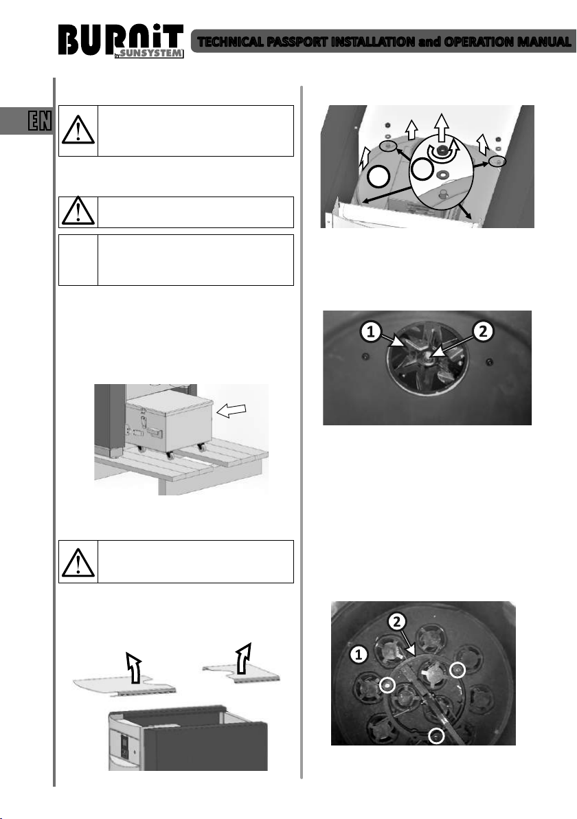
- Remove the two parts of the boiler top cover by
liing them upwards
2
- Remove the cover of the inner boiler body (2) using
wrench S13.
- Clean the fan blade (1) and the dust and soot
deposits. Use a brush. If the fan is not properly
cleaned, this will aect the boiler performance.
- Check the nut holding the fan blade (2) to be well
ghtened. Aenon: the nut is le threaded!
- Upon assembling the gasket of the fan must t well
in place. If necessary, change the fan gasket.
- Mount back the top cover
9.3.2. Cleaning and maintenance of the cleaning
system:
- Remove the top cover (9.3.1).
- Cleaning system (1). Clean the ash deposits using a
vacuum cleaner and/or a brush.
1
Diagram 15
Diagram 16
Diagram 14
- Hold a visual inspecon of the condion of the
Diagram 17
12
TECHNICAL PASSPORT INSTALLATION and OPERATION MANUAL
enre cleaning system. Also check the drive
mechanism, located outside the combuson
chamber.
- Upon detecon of worn piece/part, it is
recommended to have it replaced with a new one.
- Dismantle ue pipes from the cleaning system of
the boiler and clean them well. For this purpose:
remove the upper ring of the automac cleaning
system (2). Use wrench S10. Use a brush to clean
the ue pipes thoroughly one by one. Mount back
the ue pipes and the upper ring of the cleaning
system.
- Check silicone gasket mounted on the edge of the
boiler. Replace if cracked or hardened.
- Mount back the top cover.
- The ashes from the cleaning system are collected
in a drawer container for ash and soot. Upon
compleon of the cleaning procedure, empty the
container.
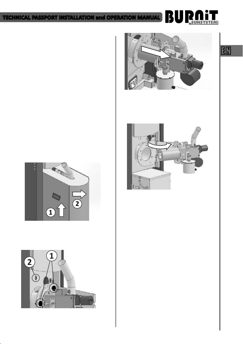
9.3.3. Servicing of the burner:
- Remove the burner casing from the boiler cabinet
body – using the handles (1) li it up then pull it
towards yourself (Diagram18).
- The rail itself is hinge-xed to the boiler body, swing
it to the right to withdraw the burner from the
boiler body. Unscrew the marked bolts to dismount
the burner from the ange holding it xed to the
rail.
EN
Diagram 20
- Remove connector (2) housing the wire connecons
Diagram 18
between the burner and the controller. Unscrew
the 2 marked plasc head bolts (1) to release the
slide rail onto which the burner is mounted.
Diagram 19
- Carefully slide out the rail with the burner mounted
on.
- Disassemble the burner combuson chamber.
Diagram 21
- Clean the inside of the burner chamber thoroughly
from residues. Use a bodkin to release all clogged
orices along the combuson chamber.
- Remove the ashes from inside the burner. Use a
vacuum cleaner and a brush.
- Inspect and clean the motors and sensors in the
boiler.
- When mounng the burner back onto the boiler,
replace the seal between the burner ange and the
boiler.
9.3.4. Feeding auger:
- Completely empty the pellet hopper.
- Dismantle the auger from the pellet hopper: release
the top of the exible hose (1) from the auger tube;
extract the auger (2) by pulling it out of the hopper.
13
TECHNICAL PASSPORT INSTALLATION and OPERATION MANUAL
EN
Diagram 22
- Clean the Auger from the ashes of the transport of
pellets: Dust o (3) and clean the ashes from the
collected (4)
- Mount the feeding auger back to the pellet hopper.
Important! Fill Auger and calibrate
it. If auger remain without fuel for
transportation will deteriorate normal
boiler operation.
9.3.5. Pellet hopper:
- Completely empty the pellet hopper
- Clean the pellet ash residues from the boom of
the hopper. Use the scraper and a vacuum cleaner.
10. CONTROLLER UNIT
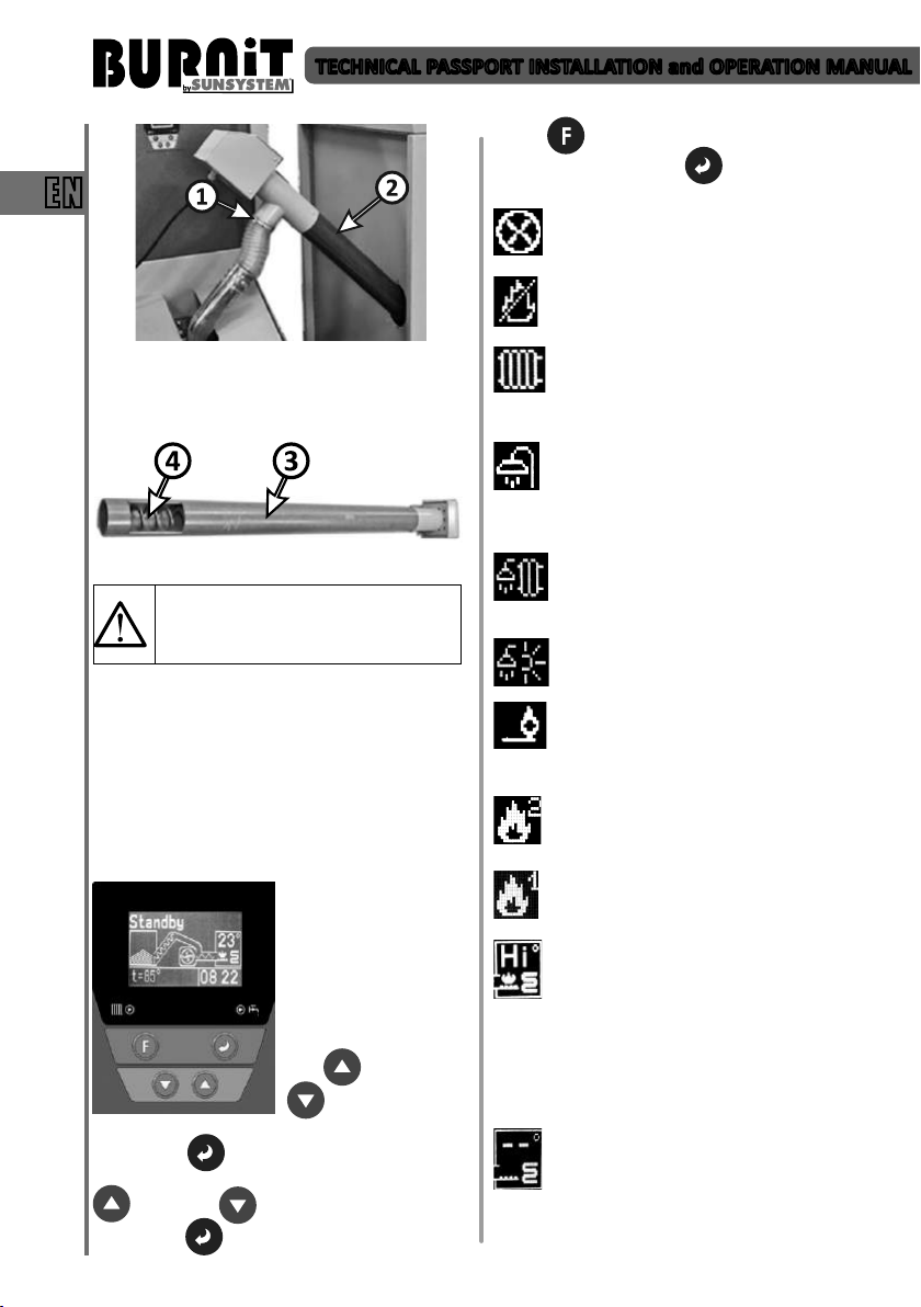
10.1. Controller view. Explanaon of buons and
indicators.
LCD screen:
The controller screen
displays the informaon
for the operaon of the
facility.
Explanaon of buons:
When logging into a
menu, use arrow keys
UP and DOWN
to move from
one page to another.
Enter buon permits adjustment of the page.
When adjustment is enabled, use arrow keys UP
and DOWN to adjust the parameter.
Press ENTER to change the parameters.
Press F to exit the menu.
Conrm with Enter buon .
Display symbols explanaon:
Auto Clean symbol appears in right upper
part of display. Acve auto cleaning symbol
means boiler automac cleaning mode.
Crossed-out ame symbol appears in upper
right part of display. Means that the boiler
enters into Exnguish mode.
CH priority /Radiator /symbol appears in
upper part of display. Means than Central
Heang priority is set to heat up the central
heang.
Domesc Hot Water /shower/ priority symbol
appears in upper part of display. Means than
DHW priority is set to heat up the domesc
hot water. When set DHW temperature is reached,
DHW pump stops and CH pump is acvated.
Parallel pumps /shower and radiator/
symbol appears in upper part of display.
Means that is set equal priority to both
pumps. They work in parallel and are
controlled by temperature sensors.
Summer mode /shower and sun/ symbol
means than is set Summer heang mode.
Only DHW pump is acve.
Burner ame symbol appears in upper right
part of display. Means that burner is
acvated. Burner goes into Ignion mode
and upcoming boiler re up.
Flame 2 symbol means Maximum output
mode of boiler. In this mode the boiler
operates at maximum output.
Flame 1 symbol means Low output mode of
boiler. In this mode the boiler operates at
minimum output.
The noce “Hi” appearance on the screen
where the boiler temperature is displayed
means that the measured boiler body
temperature is above 120°C. Flashing and
beeping alarm is acvated. When the issue is
corrected, nocaon can be deleted. Disconnect
fuel auger from boiler plug-in socket. Upon any such
occurrence please contact immediately your installer
for system checkup.
Boiler increased temperature. Those two
symbols appearance on the screen where the
boiler temperature is displayed means that
boiler temperature has increased up to 99°C.
In such a case, please contact immediately to your
installer to check the system.
14

TECHNICAL PASSPORT INSTALLATION and OPERATION MANUAL
Error symbol appears in right upper part of
display. Flashing and beeping error symbol
mean error or fault in boiler operaon. Use
“Enter“ buon to move to next screen with
error nocaon in lower le part of display. When
the issue is corrected, error nocaon can be
deleted. When disconnect the boiler from electrical
supply for few seconds and then switch on it again,
boiler goes back to normal operaon (error
nocaon is deleted).
Cleaning system of exhaust gas tubes is
activated.
S
Ash cleaning system is activated.
A
Factory seng - Alarms
BB ALARM
SENSOR E1
SENSOR E2
IGNITION FAIL Failure ignion
BURNOUT
DHW E1
DHW E2
Cleanup
TE Alarm
TE E1
TE E2
CH btm E1
CH btm E2
CH top E1
CH top E2
When restarng the controller alarm is deacvated.
Reverse re Alarm (when the
thermostat contact RB input is
open)
Boiler Temperature Sensor is
missing (input B)
Boiler Temperature Sensor Short
circuit ( input B)
Exhaust gas temparature is too
low in Operation mode. If the
exhaust gases temperature drops
below 85°C the boiler will shift into
extinguishing mode.
Water Heater Temperature Sensor
is missing (input WH)
Water Heater Temperature Sensor
Short circuit (input WH)
This alarm appears when gas
temperature rises above 180°C
This alarm appears when gas
temperature rises above 220°С
Temperature sensor of exhaust
gases is missing
Short circuit of temperature sensor
of exhaust gases
Temperature sensor of lower part
of buffer tank is missing (when in
chosen scheme with buffer tank)
Short circuit of temperature sensor
of lower part of buffer tank (when
in chosen scheme with buffer tank)
Temperature sensor of upper part
of buffer tank is missing (when in
chosen scheme with buffer tank)
Short circuit of temperature sensor
of upper part of buffer tank (when
in chosen scheme with buffer tank)
Notify the authorized installer/ service to
be performed immediately inspection of
the boiler and heating installation.
”С” symbol means that the
motor of automac cleaning
system is acvated.
The symbol “T” indicates
that a room thermostat is
connected to the controller
In “CH Priority” mode the room thermostat controls
the burner by starng and stopping it. In “DHW
Priority” mode the room thermostat controls the
heang installaon pump by starng it when the
temperature of the domesc hot water has reached
the maximum preset temperature. In “Parallel
Pumps” mode the room thermostat controls the
heang installaon pump regardless of the
temperature of domesc hot water. In “Summer
Mode” the room thermostat is disabled.
Lights for operang:
- Pump heang system
- Pump Domesc hot water.
10.2. User menu
10.2.1. Inial (start-up screen) „Standby“
buon you can browse the quick menu (boom le)
where the following read-only data is displayed:
Maximum set temperature t=85oC, temperature
of domesc hot water where such heang circuit
is connected); Light intensity in the burner; Burner
status (detected errors, if any); Date.
the facility for any reason will be displayed as an
error.
temperature of domesc hot water inside the water
heater.
15
of the burner (the boiler).
The burner is in standby
mode.
The display shows:
Temperature in the boiler
(23 degrees), me, and
by pressing the Enter
Error message. If there is an
emergency in the operaon of
Мaximum set boiler
temperature.
Current date.
Parameter t
indicates
DHW
EN
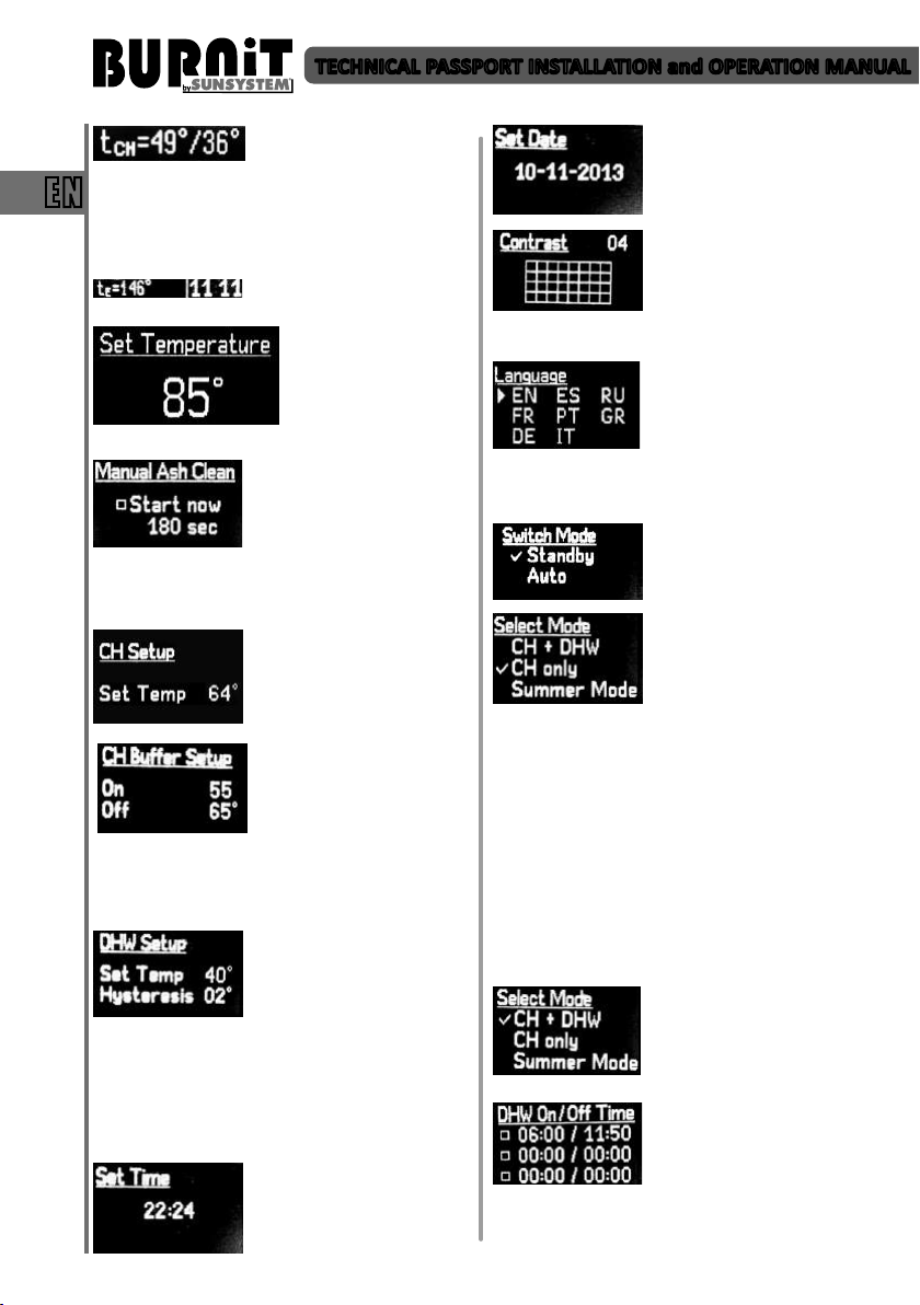
TECHNICAL PASSPORT INSTALLATION and OPERATION MANUAL
Parameter tСН indicates the
temperature at upper and boom part of the buer
tank.
EN
This screen is acve only when has been selected the
menu opon for boiler control according to buer
temperature.
set the follow parameters:
“Navigaon arrow Up” and “Navigaon arrow
Down”. Aer entering the correct value press buon
“Enter”.
. From this menu you can
scheme (with buer tank included) is selected,
whereas the two sensors reading these temperatures
are mounted in the upper, respecvely lower part of
the buer tank (cf. boiler connecon schemes).
down and using the Enter buon you can change the
parameters. You can adjust the maximum domesc
hot water temperature inside the storage tank, as
well as the switch-on hysteresis for the circulaon
pump aer a drop of DHW temperature inside the
storage tank.
value of instantaneous
Parameter tE indicates exhaust
gases temperature.
Set maximum
temperature of the boiler
through navigaon
arrows. Press buon F
and hold for 3 seconds to
Possibility for forced turn on of
ash and soot transport screw.
Time seng of screw
operaon. To set start and
operang me use buons
Use this menu to adjust switch-
on temperature of central
heang pump.
preset buer tank circulaon
pump switch-on and switcho temperatures provided
such heang installaon
From this menu you can adjust
the maximum temperature in
the domesc hot water storage
tank, whereas by navigang
from the arrow keys up and
Use UP and DOWN arrow keys
in Set Time menu to set the
unit’s built-in mer/clock.
Use UP and DOWN arrow keys
in Set Date menu to set the
date.
Use UP and DOWN arrow keys
in Contrast menu to adjust the
LCD display backlight level.
Conrm sengs by shiing to
next submenu through a single
pressing of the funconal key F.
Use this menu to choose the
language of the controller.
Choose a language by pressing
navigation arrows and button
“Enter”.
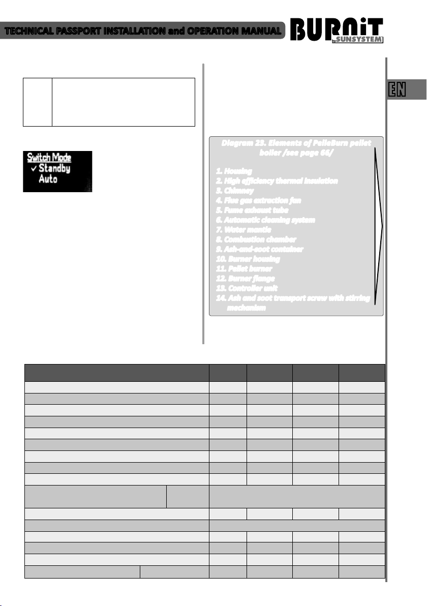
10.2.2. Burner start-up „Switch mode“
Burner start-up. Aer pressing
the “F” buon and using the
navigaon arrows, the “Auto”
or „Standby” menu is selected.
Set the priority mode of the
burner through “navigaon
arrows.”
- CH + DHW – Both pumps /CH-central heang
pump and DHW – domesc hot water pump /are
acve.
- CH only – In this mode of operaon the only acve
pump is the CH circulaon pump for the heang
installaon (CH pump). In this mode, the boiler
can be managed via a room thermostat or be
temperature-controlled by the temperature inside
the connected buer tank to it (depending on the
connecon scheme)
- Summer Mode – Boiler works for heang of
domesc hot water only.
If you have selected the (CH +
DHW) opon, upon
conrmaon of command via
the F buon you may navigate
to the next screen.
From this menu you can set up
and adjust DHW pump acvity
periods. Use the arrow keys to
set me (HH:MM). Use “Enter”
buon to checkmark desired
me period opon. If no opon is check-marked, the
controller will maintain DHW temperature as a
16
TECHNICAL PASSPORT INSTALLATION and OPERATION MANUAL
priority. Only when its preset value is reached, the CH
circulaon pump will start.
Important – The use of “External room
thermostat for the burner” option
(Thermostat) is active only if option is
selected (CH Priority – priority of central
heating installation pump).
10.2.3. Burner shut-down „Standby“
Pressing the “F” buon will
take you to the main menu and
by using the navigaon arrows
menu and conrm the selecon by pressing “F”. The
burner goes into exnguishing mode. Set the
temperature to start heang pump.
11. MOUNTING OF FUEL HOPPER FH 500
Fuel hopper FH 500 has a capacity of 500 liters
pellets. Its design allowing installation by choice on
either side of boiler. An important condition is to be
leveled. Before loading the pellets, make sure that
the hopper is clean. Empty the container for pellet
powder and dust.
Fuel hopper hatch-cover must be closed during
operation. Detailed description for the assembly of
a fuel hopper FH 500 will find the User manual for
assembling the fuel hopper FH 500.
you can select the “Standby”
12. WARRANTY TERMS
The warranty terms are described in the Service
booklet included in the supply.
EN
13. TECHNICAL FEATURES
13.1. Technical features of PelleBurn pellet boiler
13.1.1. Elements of PelleBurn pellet boiler
Diagram 23. Elements of PelleBurn pellet
boiler /see page 66/
1. Housing
2. High efficiency thermal insulation
3. Chimney
4. Flue gas extraction fan
5. Fume exhaust tube
6. Automatic cleaning system
7. Water mantle
8. Combustion chamber
9. Ash-and-soot container
10. Burner housing
11. Pellet burner
12. Burner flange
13. Controller unit
14. Ash and soot transport screw with stirring
mechanism
13.1.2. Technical parameters of PelleBurn pellet boiler
PelleBurn 15 PelleBurn 25 PelleBurn 40
Nominal heat output
Min / Max heat output
Height H
Width L / Depth D
Mantle volume
Combuson chamber volume
Combuson chamber resistance
Water side pressure drop (ΔT = 20°C) Pa/mH2O 480/0,048 850/0,085 1350/0,135
Required chimney draught
Insulaon
Electric power supply
Recommended fuel
Operang temperature range
Operang pressure
Pellet burner Pell Power kW 5÷15 8÷25 10÷40
Boiler
Doors
Weight
kW 15 25 40
kW 5÷15 8÷25 10÷40
mm 1290 1430 1700
mm 640/1120 640/1120 700/1120
l 55 70 101
l 43 53 73
Pa/mbar 10/0,10 11/0,11 12/0,12
Pa 10÷20 10÷20 10÷20
100 mm high-eciency thermal wool
lined with aluminum foil
20 mm high-eciency black veil rockwood
V/Hz/A 230/50/10 230/50/10 230/50/10
wood-pellets, diameter 6÷8 mm
°C 65-85 65-85 65-85
bar 3 3 3
kg 220 240 358
17
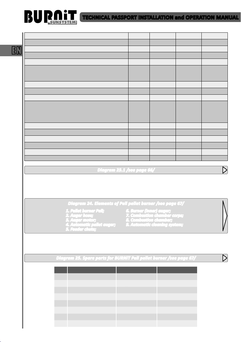
TECHNICAL PASSPORT INSTALLATION and OPERATION MANUAL
EN
Pellet fuel hopper
Cold water inlet
Hot water outlet
Safety line sleeve
Air vent
Cleaning opening
Combuson viewer
Boiler ue gas extracon fan
Burner air-feed fan
Automac cleaning device
Cleaning device motor
Burner ange
Ash and soot transport motor
Ash-and-soot container
Control unit
L 500 500 500
A, mm R ¾’’/100 R ¾’’/100 R ¾’’/100
B, mm R ¾’’/980 R ¾’’/1120 R ¾’’/1417
К
I
F,
Flue
J,
O, mm 140/300 140/300 140/300
Drain
E
V
W1,
mm
W2,
mm
P, mm 950 1090 1390
M
Z
N, mm 170 170 170
Т
U
Diagram 23.1 /see page 66/
13.2. Technical features of Pell pellet burner
13.2.1. Elements of Pell pellet burner
ø
mm
mm
133
1280
320
1220
510
133
1480
320
1385
510
150
1700
350
1665
565
Diagram 24. Elements of Pell pellet burner /see page 67/
1. Pellet burner Pell;
2. Auger hose;
3. Auger motor;
4. Automatic pellet auger;
6. Burner (inner) auger;
7. Combustion chamber corps;
8. Combustion chamber;
9. Automatic cleaning system;
5. Feeder chute;
13.2.2. Spare parts for Pell pellet burner
Diagram 25. Spare parts for BURNiT Pell pellet burner /see page 67/
№ Part Number Model PEll 25 Model PEll 40
1 82801300000002 х
1 82801300000003 х
2 82801300000010 Х
2 82801300000011 х
3 89801300000006 х
3 89801300000024 Х
4 89800000000005 Х Х
5 89801381000001 Х
18
TECHNICAL PASSPORT INSTALLATION and OPERATION MANUAL
5 89801381000002 Х
6 78801100000001 Х Х
7 32800032000001 Х Х
8 89080000000006 Х Х
9 89801200000006 Х Х
10 89800000000004 Х Х
11 32590000000092 Х Х
12 89080000000007 Х Х
13 32640000000004 Х
13 32640000000003 Х
14 32800000000006 x(C130) x(C130)
13.3. Technical features of fuel hoper FH 500
13.3.1. Elements of fuel hopper FH 500
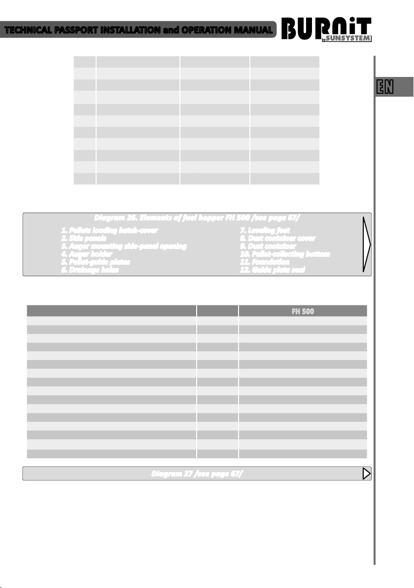
Diagram 26. Elements of fuel hopper FH 500 /see page 67/
1. Pellets loading hatch-cover
2. Side panels
3. Auger mounting side-panel opening
4. Auger holder
5. Pellet-guide plates
6. Drainage holes
13.3.2. Technical parameters of fuel hopper FH 500
Capacity l 500
Max/Min wood pellets load ø, 6÷8 mm kg 280÷300 / 15
Height H mm 1260
Width L / Depth D mm 772 / 730
Foundaon B, mm 53
Auger mounng opening C, ø mm 76
Auger holder E
Pellet-load hatch F, mm 400 / 772
Hinges G
Drainage holes J
Dust container X
Inclinaon of guide plates P 45°
Pellet-colecng boom R, mm 300 / 300
Leveling feet Z
Guide plate seal
Weight kg 82
7. Leveling feet
8. Dust container cover
9. Dust container
10. Pellet-collecting bottom
11. Foundation
12. Guide plate seal
EN
FH 500
Diagram 27 /see page 67/
19

TECHNICAL PASSPORT INSTALLATION and OPERATION MANUAL
14. RECYCLING
Submit all packaging material for recycling according
to the local regulations and requirements.
At the end of life cycle of each product its
EN
components are due to be disposed of in conformity
with regulatory prescriptions.
Obsolete equipment shall be collected separately
from other recyclable waste containing materials
with adverse effect on health and environment.
According to Directive 2002/96/EC regarding
electrical and electronic equipment waste, disposal
thereof is required separately from the normal flow
of solid household waste.
Expired appliances must be collected separately
from other recyclable waste containing substances
hazardous to health and environment. Both metal
and non-metal parts are sold out to licensed
organizations for recyclable metal or non-metal
waste collection. In any case they should not be
treated as household waste.
20

TECHNISCHES DATENBLATT MONTAGE- und BEDIENUNGSANLEITUNG
INHALT
1. ERLÄUTERUNG DER SYMBOLEN UND SICHERHEITSHINWEISE .............................................................. 22
1.1. Erläuterung der Symbolen .................................................................................................................... 22
1.2. Hinweise für den Raum der der Kesselaufstellung ................................................................................ 22
1.2.1. Hinweise für den Installateur ................................................................................................................ 22
1.2.2. Hinweise für Anlagebenutzer ................................................................................................................ 22
1.2.3. Mindestabstände bei der Montage und Brennbarkeit der Baumaterialien .. ........................................ 23
2. BESCHREIBUNG VOM ERZEUGNIS ..................................................................................................... 23
2.1. Konstruktion des Pelletkessels .............................................................................................................. 23
2.2. Konstruktion von Pelletbrenner ............................................................................................................ 24
2.3. Sicherheitsschutz des Pelletkessels und des Brenners ......................................................................... 24
2.4. Schneckeneinrichtungen für Beförderung von Pellets .......................................................................... 25
2.5. Einrichtungen für Pelletsbunker FH 500 ................................................................................................ 25
3. BRENNSTOFFE ....................................................................................................................................... 25
4. BEFÖRDERUNG VON KESSEL ................................................................................................................. 26
5. KESSELLIEFERUNG ............................................................................................................................... 27
6. MONTAGE VOM HEIZKESSEL ............................................................................................................. 27
7. MONTAGE DES HEIZKESSELS .............................................................................................................. 27
7.1. Anschluss des Kessels an einen Schornstein ......................................................................................... 27
7.2. Anschluss des Kessels an Bunker und Schnecke .................................................................................... 28
7.3. Anschluss des Kessels und Brenner an das Stromnetz .......................................................................... 28
7.4. Kessel - Anschluss an das Heizsystem ................................................................................................... 29
7.5. Schema Zusammenfügung .................................................................................................................... 31
8. FÜLLEN DER HEIZANLAGE ................................................................................................................... 31
9. NUTZUNG VOM KESSEL ......................................................................................................................... 31
DE
10. MIKROPROZESSORSTEUERUNG ............................................................................................................ 34
10.1. Ansicht vom Kontroller. Erläuterung der Druckknöpfe und der Indikatoren ........................................ 34
10.2. Benutzermenü ..................................................................................................................................... 35
11. MONTAGE VON PELLETBUNKER ........................................................................................................... 37
12. GARANTIEBEDINGUNGEN ..................................................................................................................... 37
13. TECHNISCHE CHARATERISTIKEN ............................................................................................................ 37
13.1. Technische Charakteristiken des Pelletskessels PelleFlux .................................................................... 37
13.2. Technische Parameter für Pelletbrenner BioFlux ........................................................................................ 38
13.3. Technische Charakteristiken des Pelletsbunker FH500 ......................................................................... 39
14. RECYCLING UND AUSWURF ............................................................................................................... 39
ANHANG - Diagramme .................................................................................................................................... 59
21
 Loading...