

TECHNICAL PASSPORT INSTALLATION and OPERATION MANUAL
Pellet burning boiler BioFlux series
EN
TECHNISCHES DATENBLATT MONTAGE- und BEDIENUNGSANLEITUNG
Pelletkessel Serie BioFlux
MANUEL TECHNIQUE INSTRUCTIONS pour L’INSTALLATION et L’EXPLOITATION
Chaudière à granulés de bois série BioFlux
DE
FR
model:
serial number:
Version p0.8.1

TECHNICAL PASSPORT INSTALLATION and OPERATION MANUAL
Table of contents
1. EXPLANATION OF SYMBOLS AND SAFETY INSTRUCTIONS ..................................................................... 3
EN
1.1. Explanation of symbols .......................................................................................................................... 3
1.2. Requirements to boiler installation room .............................................................................................. 3
1.2.1. Instructions to boiler installer ................................................................................................................. 3
1.2.2. Instructions to installation user ............................................................................................................. 3
1.2.3. Minimum clearances for installation. Combustibility of construction materials ................................... 4
2. PRODUCT DESCRIPTION ......................................................................................................................... 4
3. FUELS ..................................................................................................................................................... 6
4. TRANSPORTATION .................................................................................................................................. 7
5. DELIVERY OF THE BOILER ................................................................................................................... 7
6. INSTALLATION OF THE HEATING BOILER ................................................................................................ 8
7. SETUP OF THE HEATING BOILER ............................................................................................................. 8
7.1. Connecng the boiler to a chimney ....................................................................................................... 8
7.2. Pellet boiler connecon to the pellet burner, auger and fuel hopper ................................................... 8
7.3. Connecng the boiler to the mains power supply .................................................................................. 9
7.4. Connecting the boiler to the heating installation ................................................................................... 9
7.5. Connection diagrams ............................................................................................................................ 11
8. FILLING THE HEATING INSTALLATION ................................................................................................ 11
9. OPERATION OF BOILER ...................................................................................................................... 11
10. CONTROLLER UNIT ............................................................................................................................... 14
10.1. Controller view. Explanation of buttons and indicators ....................................................................... 14
10.2. User menu ............................................................................................................................................ 16
11. MOUNTING OF FUEL HOPPER FH 500 .................................................................................................. 17
12. WARRANTY TERMS .............................................................................................................................. 17
13. TECHNICAL FEATURES .......................................................................................................................... 17
13.1. Technical features of PelleBurn pellet boiler ........................................................................................ 17
13.2. Technical parameters of Pell pellet burner ........................................................................................... 18
13.3. Technical features of fuel hoper FH 500 ............................................................................................... 19
14. RECYCLING ............................................................................................................................................ 20
APPENDIX - DIAGRAMS ........................................................................................................................ 59
2
TECHNICAL PASSPORT INSTALLATION and OPERATION MANUAL
1. EXPLANATION OF SYMBOLS AND SAFETY
1.1. Explanation of symbols
CAUTION! - Important recommendation or
warning concerning safety conditions during
installation and operation of boiler.
DANGER! - fault or improper use may cause
injury or be hazardous to life of humans or
animals.
FIRE HAZARD! - fault or improper installation
and operation may cause fire.
INFORMATION – Important information on
the proper operation of the product.
1.2. Requirements to boiler installation room
This manual contains important information for the
safe and correct installation, start-up and troublefree operation and maintenance of the boiler.
The Pellet boiler can be used for heating rooms only
in the manner described in this manual.
The application and any other was the area of
operation is not recommended by the manufacturer
and is not responsible for the occurrence of defects
or failures.
Note the boiler type data on the factory rating label
and the technical data provided in chapter 13 in
order to ensure proper operation of the product.
1.2.1. Instructions to boiler installer
During installation and operation, the country-
specific requirements and regulations must be
observed:
• Local construction regulations on installation,
air supply and exhaust gas extraction as well as
chimney connection.
• Regulations and norms concerning the fitting of the
heating installation with safety devices.
• Required installation of a smoke detector in the
boiler room.
Use only original BURNiT parts
i
WARNING! Installation and setup of the
boiler should be done by an authorized
specialist / service shop and must follow
the safety instructions and rules of
operation.
INSTRUCTIONS
It is mandatory to assure a backup power
generator of corresponding rated power!
(see table 1)
DANGER of intoxication, suffocation.
Inadequate inflow of fresh air to the
boiler room may result in dangerous leak
of exhaust gases during boiler operation.
- Make sure the air inlets and exhaust gas
outlets are not clogged or closed.
- If faults are not remedied immediately, the
!
1.2.2. Instructions to installation user
$
3
boiler must not be operated.
- The user must be provided with written
instructions on the fault and the hazard it
entails.
DANGER of fire when burning flammable
materials or liquids.
- Flammable materials/liquids must not be
left in close proximity of the burner and
heating boiler.
- Instruct system user of the allowed
minimum clearances from surrounding
objects.
Customer must undergo boiler operation/
maintenance training by authorized
installer/service shop.
Table 1.
Electricity consumpon of the boiler
Maximum electrical input 780 W
Electrical input at nominal heat output 80 W
Electrical input at minimum heat output 60 W
DANGER of intoxication or explosion
Toxic gases may be discharged when
burning waste, plastics, liquids.
- Use only the fuels indicated in this manual.
- In case of danger of explosion, ignition or
discharge of exhaust gases in the room,
stop the pellet burner from operation.
CAUTION! Danger of injury / damage of
system due to incompetent operation.
- The boiler must be serviced only by persons
familiar with the operation manual.
- As user, you are only allowed to start the
boiler up, adjust the temperature of the
boiler, shut the boiler down and clean it.
- Unattended children must not be allowed
access to premises with running boiler
inside.
It is mandatory to assure a backup power
generator of corresponding rated power!
(see table 1)
EN
TECHNICAL PASSPORT INSTALLATION and OPERATION MANUAL
Customer must undergo boiler operation/
maintenance training by authorized
installer/service shop.
EN
- Operate the pellet burner on recommended fuel
only, and to that end you must regularly inspect the
boiler room.
- Do not use flammable liquids for ignition or increase
of burner output.
- Clean the burner surface using non-flammable
agents only.
- Do not place flammable objects onto the burner
housing and heating boiler cabinet or in their
proximity. (see diagram 1 for the minimum
clearances)
- Do not store flammable materials in the boiler room.
- It is mandatory to strictly observe instructions for
connecting the burner to power network as well as
to all peripherals.
- Structural changes to Dual-chamber boiler by user
can cause damage to equipment or injury.
- Do not allow contact transmission of electrical wire
or touch any part of the boiler, where the surface
temperature can exceed 70°C.
- This manual should be kept throughout the lifetime
of the boiler.
1.2.3. Minimum clearances for installation and
flammability of construction materials
The applicable minimum clearances in your country
may differ from the ones specified below. Please,
consult your installer.
The minimum distance from the burner, heating
boiler or exhaust gas pipe to objects or walls must be
at least 200 mm.
Safety rules for user operation:
CAUTION! Hot surface!
Risk of burns if you touch the running
system. Burner housing, body and flange
are hot surfaces during burner operation.
It is strictly prohibited to open boiler
inspection doors with the burner running.
The hopper hatch cover is not allowed to
remain open for longer periods of time.
Also, exercise caution when touching the
observation port for monitoring the burning
process. It may be hot.
Table 2. Flammability of construction materials
Class А – non-
flammable
Class B – hardly
flammable
Class С1/
С2 – Medium
flammable
Class C3 – easy
flammable
For general safety considerations, we recommend
that the boiler be placed on a foundation made of
class A material, see table 2.
Diagram 1. Recommended clearances
between boiler and walls /see page 59/
Ecological and highly-efficient pellet boiler PelleBurn
is designed for firing wood pellets. The mantle fully
covers the combustion chamber. Efficiency rate
reaching 91%. Approved in accordance with EN 3035, class 5. Set includes pellet boiler, pellet burner,
auger and pellet fuel hopper (option).
2.1. Design structure of boiler PelleBurn.
Cylindrical body design is made of high-quality
boiler steel sheets with thickness of 4 mm for the
combustion chamber and 3 mm for the water mantle.
• Ecological. A high-end pellet boiler. The wood
pellets used for fueling the boiler are a renewable
fuel with minimum carbon emissions and ultimate
burning efficiency.
• Automated. Owing to an improved algorithm
with optional adjustment of a wide variety of
parameters, the system may befinely tuned to
any particular heating system to achieve optimum
efficiencyand fuel consumption.
1) fully automated ignion and pellet feed;
2) exhaust fan ensures stable operaon of the
boiler;
3) boiler-and-burner self-cleaning funcon;
4) controls the operaon of central heang
circulaon pump;
5) controls the operaon of DHW (domesc hot
water) pump;
6) controls by room thermostat;
7) ue gas sensor
4
Stone, bricks, ceramic tiles, baked
clay, solutions, plaster free of
organic additives.
Gypsum board panels, basalt fiber
needled felt, fiberglass board,
AKUMIN, Izomin, Rajolit, Lignos,
Velox, Heraklit.
Wood beech, oak. Wood softwood,
layered wood
Asphalt, cardboard, cellulose, tar,
fiberboard, cork, polyurethane,
polyethylene.
2. PRODUCT DESCRIPTION
Controller functions:
TECHNICAL PASSPORT INSTALLATION and OPERATION MANUAL
• Efficient. To keep from losing heat into the
ambience, the boiler is insulated on the outside
by 100 mm high-temperature wool. With its
state-of-the-art combustion control system
and cylindrical body design construction the
PelleBurn boiler achieves efficiency rate of as
much as 91%.
2.2. Design of pellet burner Pell
The burner is made of high-quality stainless steel
able to withstand temperatures of up to 1150°С. The
burner must be installed on a heating boiler.
The burner consists of two parts: combustion
chamber tube and external tube with sheet metal
mantle. Longitudinally, under the housing, there are
blow chamber, fuel ignition heater, fan and power
supply. On the upper part of the burner there is a
feeder chute to which the pellet auger is attached. The
combustion chamber consists of two tubes:
Ember resistant steel tube inside the burner with
holes for air intake along its entire length, opening
for the hot air from the fuel ignition heater, opening
for photosensor.
Outer stainless steel tube. Between the two tubes
there is a gap which provides for free circulation of
the air necessary both for cooling and oxygen supply
into the combustion chamber.
The feeder chute allows 360° rotation for its best
convenient positioning when connecting the pellet
auger to the hopper.
Diagram 2. Design of Pellet Burner Pell
/see page 59/
Other elements of the burner are
• Internal auger.
• Dry contactless resistance heater assuring ignion
of fuel.
• Pneumac cleaning system of the combuson
chamber.
• Feed fan, smooth regulaon (0% to 100 %).
• Telescopic pull-out system of burner Pell for easy
maintenance.
2.3. Safety devices of pellet boiler-and-burner
A complex of safety devices provide for the safety of
the appliance. Air-feed fan, step –regulated, controls
the combustion according to energy needs and is
maintained in optimal working order. Independent
STB thermostat shut-off the burner and shut off the
air feeding in the combustion chamber in case of
rising boiler temperature.
• Elbow-shape feeder chute. The geometrical shape
of burner feeder chute prevents backfire entry
from burner into pellet hopper. The flexible tube is
melted at a temperature above 80°C. Thus prevent
access to the hopper of the fire.
• Thermostatic protection (80°С). The thermostatic
protection is fitted on the feeder chute. When
the surface of the feeder chute reaches 80°С, the
control stops the feeding of pellets into the burner
and signals for fault (BB Alarm).
• Fuse. In case of electrical fault in the system of the
burner (short circuit, current overload, etc.), the
overload is borne by the electrical fuse fitted on the
main control panel of the burner (10 А).
• Power interruption. Innovative controller. In case
of power interruption, all parameter settings are
stored in the memory of the controller. Upon the
subsequent restart of the burner, the controller
resumes the execution of the program from the
point when the power interruption occurred.
2.4. Design of pellet auger
The auger transports pellets from fuel hopper to
burner. Auger elements are: auger pipe, auger hose,
motor, conveyor belt for moving the pellets.
D i a g ram 3 . D es ig n of pellet auger
/see page 59/
2.5. Design of fuel hopper FH 500
Pellet hopper, designated to serve biomass
pellet-fired boilers. Pellet hopper design allowing
installation by choice on either side of boiler.
Made of cold-rolled steel sheets with PVC coating.
Comfortable pellet charging hatch. Pellets inside
hopper are fed into auger in order of reception.
Precision leveling of hopper possible via screw-in legs.
Elevated foundation with drain holes and container
for separation and removal of pellet powder.
The hopper capacity is determined using as
calculation base the daily or weekly fuel consumption
rate of burner. The pellet hopper usable volume of
500 litters allows charging of 280-300 kg of pellets
with diameter 6 mm, and top-up/refill once a week
(for burner of rated power up to 40 kW).
Diagram 4. Design of fuel hopper FH 500
/see page 59/
5
EN

TECHNICAL PASSPORT INSTALLATION and OPERATION MANUAL
All pellets are biomass manufactured from common
3. FUEL
low-growing plants and trees. The most common
household type pellets are made of sawdust and
EN
milled wood chippings which are waste material
from wood used in the production of logs, furniture
and other products. Wood is the richest raw material
which does not have any impact on the production
costs of food products or ethyl alcohol (ethanol).
The raw material is processed under high-pressure
and temperature and is pressed to produce smallsize cylindrical pellets. The production process may
utilize soft wood material (such as softwood, pine),
hardwood (oak) as well as recycled waste wood.
Wood pellets are produced in hammer mills or wood
pellet plants.
Advantages of wood pellets:
Convenient storage.
Pellet bags can be stored on a small area in a dry
garage, basement, service room or shed.
Easy loading.
In most cases the boiler hopper needs loading only
once a week – this depends on the hopper capacity.
Better control of fuel quantity.
The small size of the pellets allows for precise fuel
feeding. On the other hand, the supply of air for
reaching optimal combustion efficiency is easier
to adjust since the fuel quantity in the combustion
chamber remains constant and predictable.
Fuel efficiency.
by consistently low moister content of pellets
(consistently under 10% as opposed to 20% to 60%
moisture content of the logs). Low moisture content,
controlled fuel portions and precise air setting means
high combustion efficiency and very low carbon
oxides in the flue gases.
When purchasing pellets, ask for
conformity declaration and certificate
issued by an accredited laboratory
and make sure the fuel meets the
requirements indicated in the manual.
If you purchase large amount of pellets
i
(bulk supply for the entire heating season
for example), ask your supplier to provide
accurate and true information about the
storage conditions.
We recommend to use pellet with size of 6 - 8 mm.
Density 600 - 750 kg/m3 heating value 4.7-5.5 kWh/
kg. Ash content – less than 1% and moisture content
up to 8%., EN 14961-2:2011.
The optimal density of the pellets which guarantees
their quality is 605-700 kg per cubic meter.
Pellet moisture content must not exceed 10%. Make
sure you store your fuel in a dry and well-ventilated
place.
The optimal pellet ash content is ≤ 1%. This also
provides for less frequent cleaning intervals for the
burner.
The table below contains the parameters which we
recommend that you take into consideration when
choosing fuel for your Pell burner.
High combustion efficiency is also determined
Table 3. European Certification of Wood Pellets for Heating Purposes
Parameters Units ENplus-A1 ENplus-A2 EN-B
Diameter mm
6 (± 1)
8 (± 1)
Length mm 15 ≤ L ≤ 40
Bulk density kg / m
2
≥ 600 ≥ 600 ≥ 600
1)
6 (± 1)
8 (± 1)
15 ≤ L ≤ 40
1)
Caloric/heang value MJ / kg ≥ 16,5-19 ≥ 16,3-19 ≥ 16,0-19
Humidity /moisture Ма .-% ≤ 10 ≤ 10 ≤ 10
Dust Ма .-% ≤ 1
Mechanical durability Ма .-% ≥ 97,5
Ash Ма .-%
2)
≤ 0,7 ≤ 1,5 ≤ 3,5
3)
4)
≤ 1
≥ 97,5
3)
4)
Melng point of ash °C ≥ 1200 ≥ 1100 Chlorine content Ма .-%
Sulfur content Ма .-%
Nitrogen content Ма .-%
Copper content mg / kg
2)
2)
2)
2)
≤ 0,02 ≤ 0,02 ≤ 0,03
≤ 0,03 ≤ 0,03 ≤ 0,04
≤ 0,3 ≤ 0,3 ≤ 1,0
≤ 10 ≤ 10 ≤ 10
6 (± 1)
8 (± 1)
15 ≤ L ≤ 40
3)
≤ 1
≥ 96,5
1)
4)
6

TECHNICAL PASSPORT INSTALLATION and OPERATION MANUAL
Chromium content mg / kg
Arsenic content mg / kg
Cadmium content mg / kg
Mercury content mg / kg
Lead content mg / kg
Nickel content mg / kg
Zinc content mg / kg
1)
not more than 1% of the pellets may be longer than 40 mm, max. length 45 mm;
2)
dry weight;
3)
particles <3.15 mm, particulate matter, before handing over the goods;
4)
measurements with Ligno-Tester limit value ≥ 97,7% by weight.
4. TRANSPORTATION OF THE BOILER
We recommend to transport the heating boiler to the
installation site in its packaging placed on the pallet.
During transport and installation, depending on the
weight, suitable safety devices should be used in
accordance with Directive 2006/42/EC.
When transporting items weighing more than 30 kg,
the use of pallet jack, fork truck or other hoisting
devices is a must.
Product must be in original packaging following
2)
2)
2)
2)
2)
2)
2)
≤ 10 ≤ 10 ≤ 10
≤ 1,0 ≤ 1,0 ≤ 1,0
≤ 0,5 ≤ 0,5 ≤ 0,5
≤ 0,1 ≤ 0,1 ≤ 0,1
≤ 10 ≤ 10 ≤ 10
≤ 10 ≤ 10 ≤ 10
≤ 100 ≤ 100 ≤ 100
motor drive (noise, friction) or failure of high-tech
elements such as broken controller-screen, contact
your nearest authorized service center for repairs
and maintenance.
The boiler is securely fastened with fasteners to a
wooden pallet.
Important: When installing the boiler, the
wooden pallet onto which the boiler is
placed must be removed by unscrewing
the bolted connections using flat ring
wrench S13.
the instructions on the label - to be protected from
adverse weather conditions (snow, rain and dust)
from the shocks, and other activities likely to cause
Diagram 5. Indications dimensions /see
page 59/
damage. In case of malfunction of the fan or the
Table 4. Overall dimensions of Set Pellet boiler PelleBurn, Pellet burner Pell and Fuel Hopper FH 500
PelleBurn 15 25 40
A1, mm
A2, mm
A3, mm
B1, mm
B2, mm
B3, mm
C, mm
D1, mm
D2, mm
D3, mm
Weight, kg
Pellet boiler, burner and pallet
Auger, box
Fuel Hopper, box
Pellet boiler, burner and pallet
Auger, box
Fuel Hopper, box
Pellet boiler, burner and pallet
Pellet boiler, burner and pallet
Auger, box
Fuel Hopper, box
Pellet boiler, burner and pallet
Auger, box
Fuel Hopper, box
710 710 810
120 120 120
840 840 840
1100 1100 1320
260 260 260
810 810 810
125 125 125
1430 1630 1775
1700 1700 1700
1220 1220 1220
185 200 325
8 8 8
48 48 48
EN
5. DELIVERY OF THE BOILER
• Inspect the integrity of the packaging upon
delivery.
• Check whether all components have been
delivered to you.
Boiler consignment package includes:
1) Pellet boiler PelleBurn with pellet burner Pell
2) Auger
3) Fuel hopper FH 500 (opon)
4) Safety valve 3 bar.
5) Fire irons
6) Technical passport. Installaon and operaon
manual
7) Service booklet and Warranty card
If any of the above items are missing, contact your
supplier.
7
TECHNICAL PASSPORT INSTALLATION and OPERATION MANUAL
6. INSTALLATION OF THE HEATING BOILER
The assembly, installation and set-up of the
EN
boiler must be performed by a technician
authorized for such operations.
Installer must indicate to the user of the
installation the minimum clearances from
flammable materials and liquids.
Requirements:
- Boiler room must be frost-proof;
- Boiler room must allow for continuous access of air
necessary to maintain combustion;
- Boilers must not be placed in inhabitable rooms;
- All boiler rooms must have correctly calculated vent
depending on the boiler output. The vent must be
protected by means of a net or grate.
The size of the vent is calculated according to the
formula:
А=6,02*Q - where:
А – area of the vent in cm2,
Q – boiler output in kW
- Remove the packaging without polluting the
environment;
- Observe building supervision instructions, in
particular the existing Ordinance on combustion
devices and storage of combustion materials, on
building requirements applicable to installation sites
and on ventilation;
- The boiler must be placed on a foundation whose
surface area is larger than the base of the heating
boiler according to diagram 1;
- The boiler must be placed in a position which allows
for the easiest possible cleaning and servicing;
- Installation must be carried out according to
installation diagram 1 which shows the boiler
housing;
- No objects made of flammable materials or liquids
may be placed on/near the boiler;
7. SETUP OF THE HEATING BOILER
7.1. Connecng the boiler to a chimney
Boiler-to-chimney connecon must always comply
with the exisng standards and rules. The chimney
must provide sucient draught for evacuaon of the
smoke under any condions.
The proper funconing of the chimney requires
adequate sizing of the chimney itself since the
draught it produces aects combuson, boiler’s
output and life span.
The draught created by the chimney is in funconal
relaon to its cross-secon, height and the roughness
of its interior walls. No other appliance may be
connected to the chimney serving the boiler. Chimney
diameter must not be smaller than the ue outlet
of the boiler. Flue outlet must be connected to the
chimney opening. In terms of mechanical properes,
the ue outlet must be sturdy and properly sealed (to
avoid gas leak) and allow for easy access for cleaning
on the inside. The inner secon of the ue outlet
must not be greater than the eecve secon of the
chimney and must not narrow. Avoid using elbow
joints.
The chimney cleaning opening has to be in its lowest
part. The chimney’s wall has to be three plied where
the medium layer is from mineral wool. The thickness
of the insulaon is not less than 30 mm when the
chimney is seng up inside the house and the
thickness is 50 mm, when the seng up is outside.
Please entrust choosing a chimney and its installaon
by a qualied professional. The required distance
between the boiler and the chimney is 300-600 mm.
Draught regulator (1) must be installed at least 600
mm from the joint (connecon).
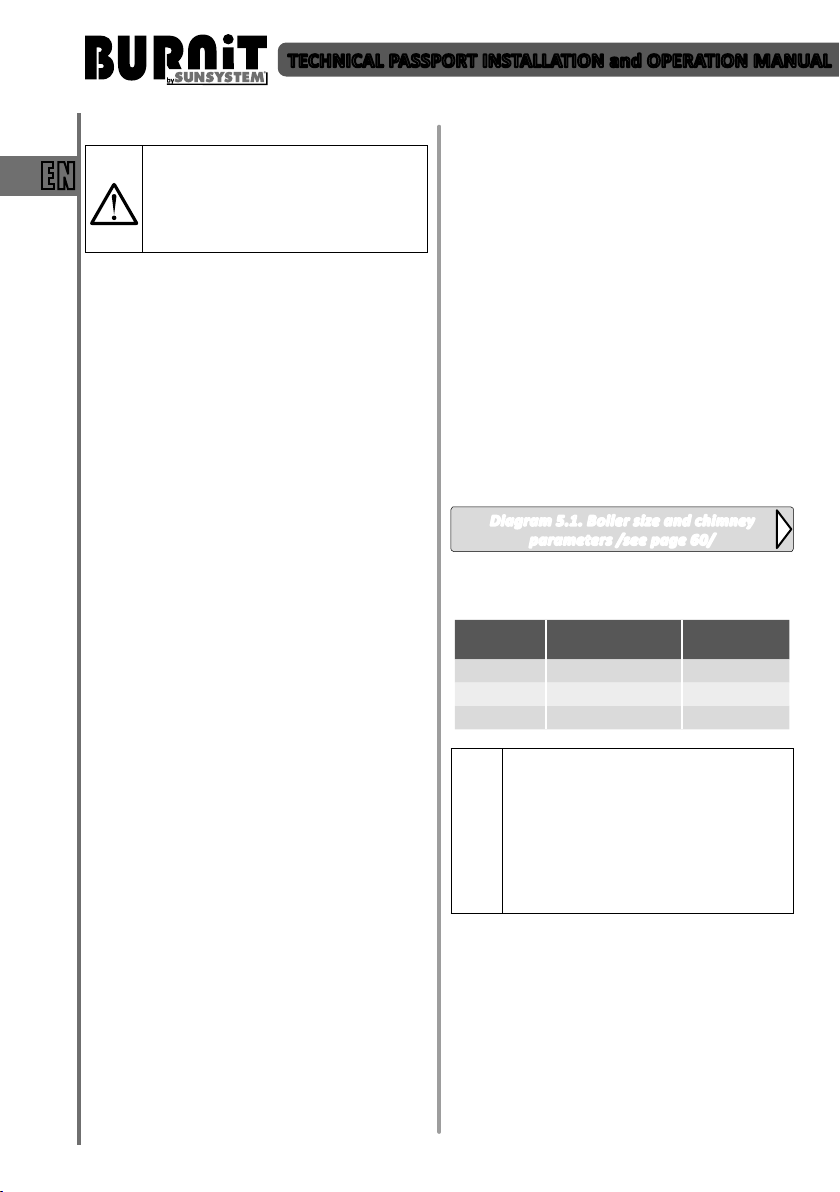
Diagram 5.1. Boiler size and chimney
parameters /see page 60/
Table 5. Recommended minimum sizes and chimney
Boiler
output
15 kW Ø 130 10-20
25 kW Ø 130 10-20
40 kW Ø 150 10-20
Data in the tables are for indicative
purposes.
Draught depends on the diameter, height,
uneven sections along the chimney
surface and differences in temperature of
i
combustion products and outside air. We
recommend that you use chimney fitted
with flue terminal. Heating specialist must
calculate the precise sizing of the chimney.
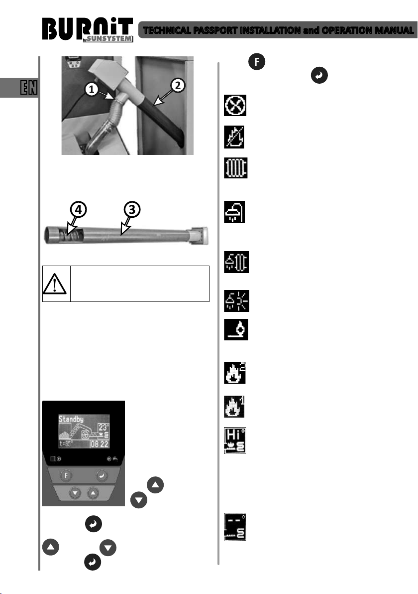
7.2. Pellet boiler connecon to the pellet burner,
auger and fuel hopper
- Take the auger hose (from the auger set). Using a
bracket, clamp one end of the hose onto the motorend outlet of the pellet auger.
- Using a bracket, clamp other end onto the feeding
chute of burner
- Remember pellet auger must be installed at 45°
angle to the ground horizontal surface.
- Fill the hopper with fuel (see table 2 for parameters
of the fuel types used)
8
dra
Chimney
diameter, mm
Chimney
dra, Pа
TECHNICAL PASSPORT INSTALLATION and OPERATION MANUAL
- Plug the power cord of the pellet auger into the
indicated Schuko-type boiler socket on the le side
of the boiler housing.
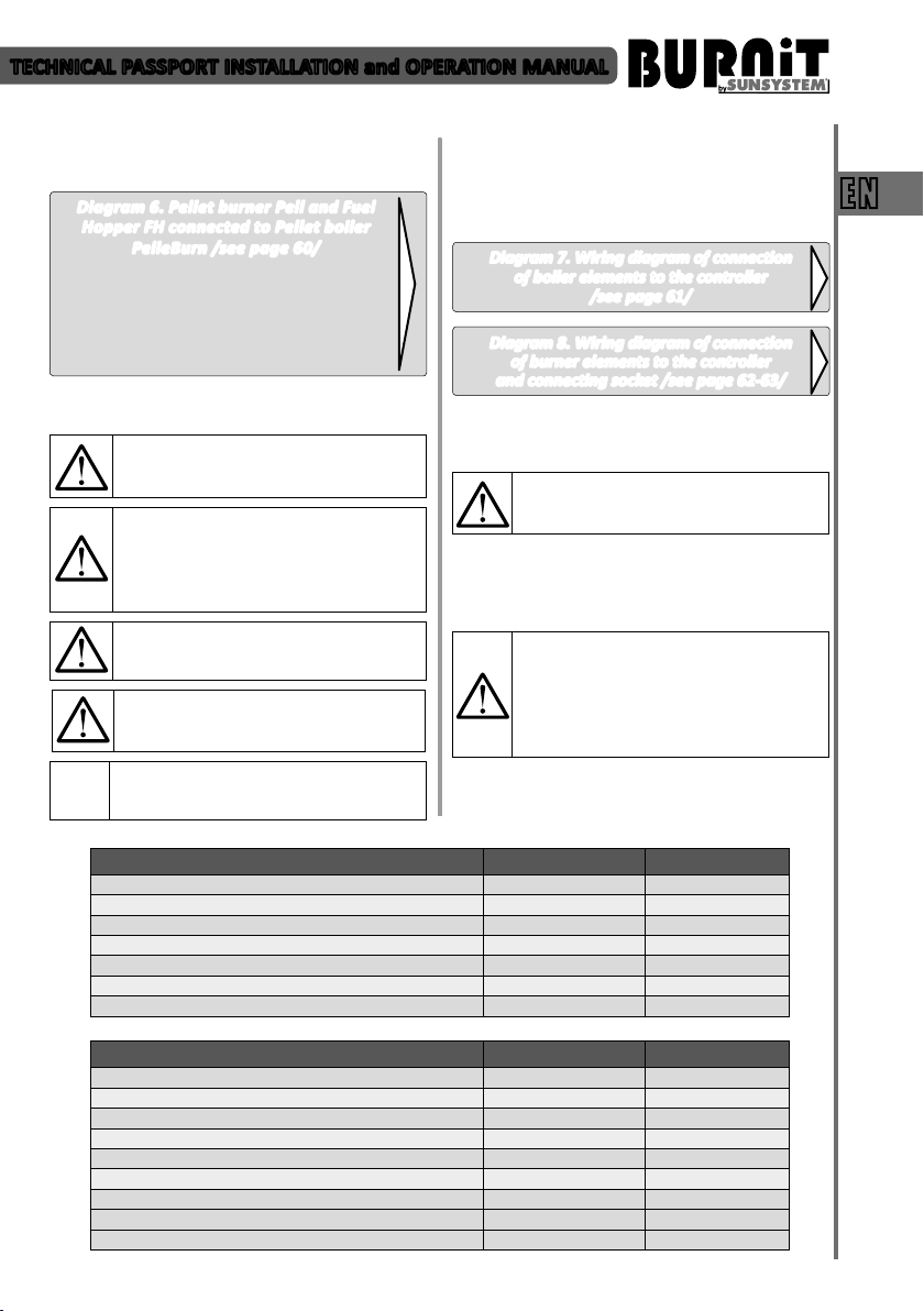
Diagram 6. Pellet burner Pell and Fuel
Hopper FH connected to Pellet boiler
PelleBurn /see page 60/
1. Pellet boiler PelleBurn;
2. Pellet burner Pell;
3. Auger hose;
4. Auger;
5. Fuel Hopper FH.
7.3. Connecng the boiler to the mains power
supply
Such connecon must be performed by a
technician / service shop authorized for
such operaons.
Cauon! ELECTRIC SHOCK HAZARD!
- Before opening the unit: switch o the
voltage and secure the unit against
accidental restart.
- Observeinstallaoninstrucons.
Improper cable connecons may damage
the regulator!
The device may be damaged if struck by
a lightning. Make sure it is unplugged
during the storms.
It is mandatory to assure a backup power
generator of corresponding rated power!
(see table 1)
Legend /Diagrams 7 and 8/
To bring into exploitaon the boiler and auger must
be connected to the electricity network 220V/50Hz
with power cord. Create ght connecon with
the electrical mains which complies with the local
regulaons.
Diagram 7. Wiring diagram of connecon
of boiler elements to the controller
/see page 61/
Diagram 8. Wiring diagram of connecon
of burner elements to the controller
and connecng socket /see page 62-63/
7.4. Connecng the boiler to the heang
installaon.
Such connecon must be performed by a
technician / service shop authorized for
such operaons.
When the boiler is connected to a heang system,
it is mandatory to install a 3 bar relief valve and
expansion vessel. No shut-o ngs may be installed
between the relief valve, expansion vessel and boiler.
It is mandatory to install a three-way valve
(Laddomat or similar) or a four-way mixing
valve which to ensure that the temperature
of the heang medium fed into the boiler
from the heang installaon is at least
65°С.
Elements INPUTS Symbol
Room thermostat I02 RT
Boiler sensor I03 B
STB termostat of the burner I04 RB
Sensor water heater I05 WH
Sensor exhaust I06 PT
Temperature sensor at the top of the buffer I08 AT
Temperature sensor at the bottom of the buffer I17 NA1
EN
Elements OUTPUTS Symbol
Fan smoke gases О 01 FSG
Ignitor О 03 IGN
Fan cleaning of the burner О 04 FC
Screw fuel О 05 SF
Screw burner О 06 SB
Pump heang О 07 PH
Pump water heater О 08 PHW
Electric motor of self-cleaning system О 10 CS
Electric motor of clean ash О 11 CA
9

TECHNICAL PASSPORT INSTALLATION and OPERATION MANUAL
Table 6. TROUBLE-SHOOTING TABLE
Cause Solution
EN
Duetounsealedconnecons Installtheconnecngpipingstrain-freetotheboilerconnecons.
Due to freezing
Boiler water too hot, heang bodies too cold
1. Hydraulic resistance is too high.
2. Air in the system
3.Inoperablecirculaonpump
The STB safety thermostat has been
triggered.
Unable to reach normal temperature mode of 65°-85° С
Inadequate sizing and/or
combinaonofheangappliances
Ejecon of unburned pellets into the combuson chamber of the boiler
Poor adjustment of the fuel-to-air
raofromtheburnercontroller
Ulizaonoflow-qualitypellets
Formaon of clinkers and noncombusble inclusions inside burner body
Ulizaonoflow-quality pellets(see
secon3.Fuel)
Low performance of the automac
cleaning system
Impropersengoffuel-airmixture Adjust using gas analyzer
Poor chimney draught or high
internal resistance of the boiler
combusonchamber
Blockage of burner combuson
chamber due to build-up of
noncombusblematerials
Impropersengoffuel-airmixture Adjust using gas analyzer
Dust on the photosensor It is necessary to clean the photosensor. Refer to the manual for the
Boiler temperature too high. Controller failure.
Gridpoweructuaons
Power failure
High temperature of exhaust gases.
High temperature alarm is turning
on
High temperature in boiler water
jacket and low temperature in the
buertank.
Installaon damage
Ifthe heang installaon,including thepipingnetwork, hasnotbeen
built frost-proof,we recommend that you llthe heanginstallaon
withaliquidwhichhaslowfreezingpointandcorrosionproteconand
anfreezeagent.
Make sure the circulaon pump has been properly selected and the
heanginstallaonisoftheproperdimensions.(Youmustcontactyour
installer.)
Uponreachingatemperatureof95°С,thethermostacsafetyprotecon
device is triggered and the fan is turned o. To resume protecon,
remove the black cap on the front panel of the boiler and press the
buonon theSTB-thermostat.Contactyourinstallertodeterminethe
causeofprotecontriggering.
Low boiler temperature.
Immediately consult your installer about the problem.
Contactyour installer.It is necessarytoset the burnerproperlyusing
gas analyzer
Use only fuelwhichmeetstherequirementsspecied in the manual.
(seesecon3.Fuel)
Useonlyfuelwhichmeetstherequirementsspeciedinthemanual.
Increaseturn-onfrequencyoftheautomaccleaningsystem.
Smoke in the pellet hopper
Immediately consult your installer about the problem.
Itisnecessarytocleantheburnercombusonchamberusingbrush
cleaning procedure.
It is mandatory to assure a backup power generator of corresponding
ratedpower!(seetable1)
Fume exhaust tubes of boiler water jacket are clogged with soot.
Reduced heat transfer. The boiler should be cleaned. Please contact an
authorized specialist / service shop to clean the boiler.
1.IncorrectON/OFFtemperaturesengsofpumps.
2.Incorrectsizingofheangsystem.
10

TECHNICAL PASSPORT INSTALLATION and OPERATION MANUAL
7.5. Connection diagrams
Such connecons must be performed by
a technician / service shop authorized for
such operaons.
Diagram 9. Connecon of boiler PelleBurn to three-way valve/see page 64/
Diagram 10. Connecon of boiler PelleBurn to P type buer tank
Diagram 11. Connecon of boiler PelleBurn to combi tank KSC2,
at plate solar collector PK and three-way valve/see page 65/
Diagram 12. Connecon of boiler PelleBurn to solar tank SON, buer thank P,
at plate solar collector PK and three-way valve /see page 65/
Problem Prevenon
Possible installaon damage due
to strains in the material caused by
temperature dierences
Danger of installaon damage due to
accumulaon of deposits
Condensate formaon and tar deposits
may shorten boiler’s operaonal life.
and three-way valve /see page 64/
8. FILLING THE HEATING INSTALLATION
Table 6
Fill the heang installaon only in cold condions (inlet
temperature must not exceed 40°C).
- Do not operate the heang boiler for a long period of me in
paral load mode
- The temperature at the boiler inlet must not be less than 65°C,
boiler water temperature must be between 80°C and 85°C.
- Use the boiler for a short period to heat warm water in the
summer.
EN
9. OPERATION OF BOILER
Failure to observe the installation and
operating requirements described in the
manual and the service booklet voids the
warranty.
9.1. Operaon of pellet boiler PelleBurn with pellet
burner Pell
Ignion. Aer starng the burner up from the
control panel, the main pellet auger conveys certain
amount of fuel from the pellet hopper to the burner.
This specic amount of pellets is set by the installer
and depends on the fuel characteriscs. The fedin quanty of pellets is conveyed from the auger
conveyor built in the burner to the combuson
chamber where it is being ignited using hot air.
Burning. The burning process takes place in the
combuson chamber and, aer it has been fed into
the combuson chamber, the fuel is then transported
from the internal auger conveyor to the combuson
chamber in porons. This allows for constant
and opmal burning rate of the fuel. The boiler is
controlled and operated by sensor exhaust. This
sensor measures the temperature of exhaust gases
and provides informaon to the control unit ignion
or disconnuaon of combuson. The output of the
burner is determined by the intervals preset on the
control panel taking into account the heang value,
size and density of the pellets.
Automac cleaning system. The pellet boiler is
equipped with innovave automac cleaning system
for combuson chambers of both devices.
A powerful cleaning motor built in the burner
body, air is being blown in at high speed and rate
thus removing all residues – ash, noncombusble
inclusions, etc. built up into the combuson chamber
of the boiler.
At the same me the boiler turns on automac ash
removal which is transported to the ash container
through screw located in the lower part. These
automac cleaning cycles last several seconds and
can be addionally adjusted as well as their repeat
rate depending on the load of the burner.
9.2. Important recommendaons for long-lasng
and correct operaon of the boiler
- For assembly and installaon of the burner follow
the requirements in this manual.
- Use only recommended in this manual fuel.
- Disassemble the burner from the boiler body
before clean it. Depending on fuel and burner
sengs, clean the pellet burner once a month.
- User`s training for operaon and maintenance of
11
TECHNICAL PASSPORT INSTALLATION and OPERATION MANUAL
burner is performed by an authorized installer or
service shop.
Failure to observe the installation and
EN
9.3. Requirements for the cleaning and maintenance
of PelleBurn pellet boiler with pellet burner.
- It is mandatory to clean the ashes from the container
once a week. Unhook the buckles on both sides of
ash container. Pull ash container out of the boiler
and clean it. Once you have emped the container
of ashes, please make sure you close the container
cover ghtly, buckle-lock it to the container buckles,
then buckle-lock the container to the boiler buckles.
- It is mandatory to clean once a month the
Before the start of the heang season it is mandatory
to check and clean the following components of the
boiler:
9.3.1 Cleaning and maintenance of sucon fan
operating requirements described in the
manual and the service booklet voids the
warranty.
Attention! Important instructions
regarding cleaning of boiler.
Caution! Hot surfaces.
Before cleaning the boiler, make sure the
fire in it has died out and the boiler has
cooled down.
Diagram 13
combuson chamber of the burner.
Attention! Cleaning and maintenance of
the boiler should be carried out only by an
authorised installer/service shop.
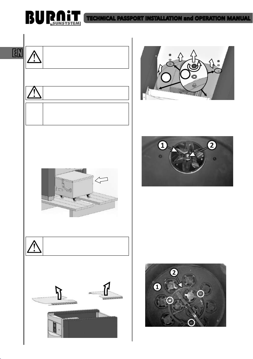
- Remove the two parts of the boiler top cover by
liing them upwards
2
- Remove the cover of the inner boiler body (2) using
wrench S13.
- Clean the fan blade (1) and the dust and soot
deposits. Use a brush. If the fan is not properly
cleaned, this will aect the boiler performance.
- Check the nut holding the fan blade (2) to be well
ghtened. Aenon: the nut is le threaded!
- Upon assembling the gasket of the fan must t well
in place. If necessary, change the fan gasket.
- Mount back the top cover
9.3.2. Cleaning and maintenance of the cleaning
system:
- Remove the top cover (9.3.1).
- Cleaning system (1). Clean the ash deposits using a
vacuum cleaner and/or a brush.
1
Diagram 15
Diagram 16
Diagram 14
- Hold a visual inspecon of the condion of the
Diagram 17
12
TECHNICAL PASSPORT INSTALLATION and OPERATION MANUAL
enre cleaning system. Also check the drive
mechanism, located outside the combuson
chamber.
- Upon detecon of worn piece/part, it is
recommended to have it replaced with a new one.
- Dismantle ue pipes from the cleaning system of
the boiler and clean them well. For this purpose:
remove the upper ring of the automac cleaning
system (2). Use wrench S10. Use a brush to clean
the ue pipes thoroughly one by one. Mount back
the ue pipes and the upper ring of the cleaning
system.
- Check silicone gasket mounted on the edge of the
boiler. Replace if cracked or hardened.
- Mount back the top cover.
- The ashes from the cleaning system are collected
in a drawer container for ash and soot. Upon
compleon of the cleaning procedure, empty the
container.
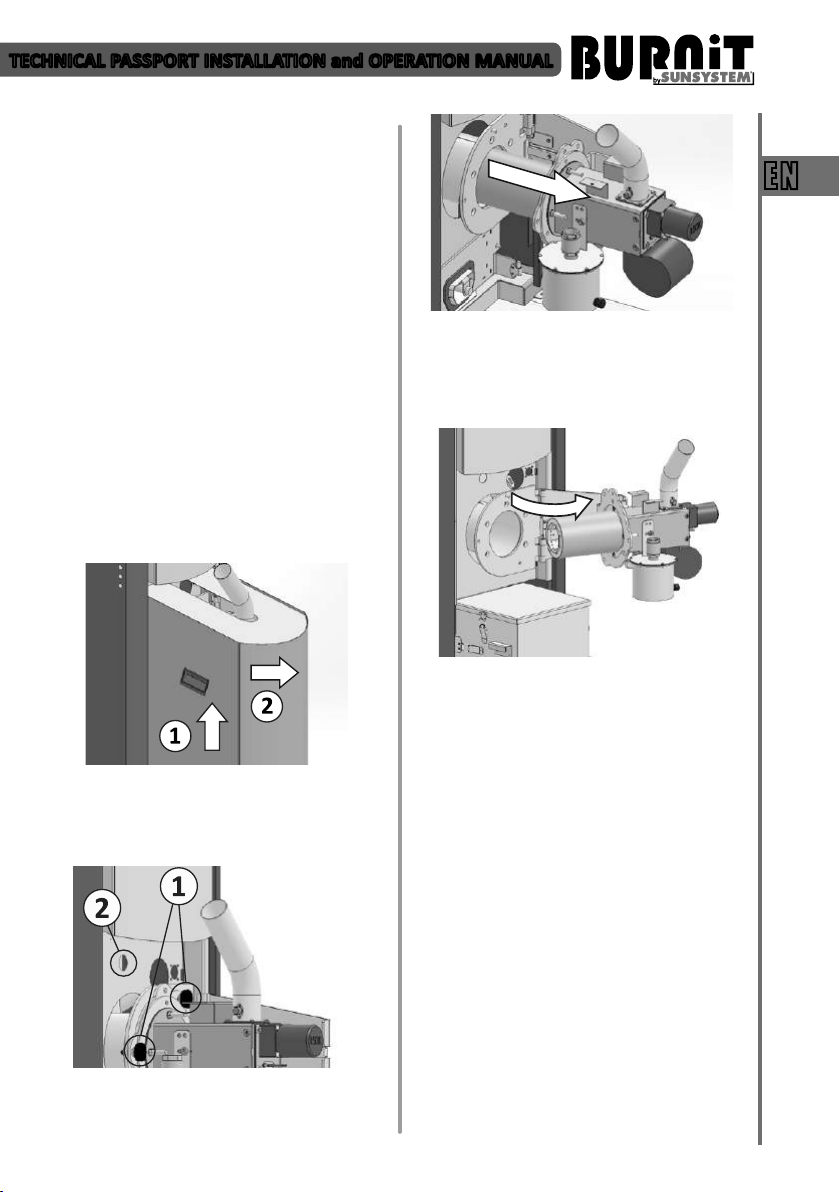
9.3.3. Servicing of the burner:
- Remove the burner casing from the boiler cabinet
body – using the handles (1) li it up then pull it
towards yourself (Diagram18).
- The rail itself is hinge-xed to the boiler body, swing
it to the right to withdraw the burner from the
boiler body. Unscrew the marked bolts to dismount
the burner from the ange holding it xed to the
rail.
EN
Diagram 20
- Remove connector (2) housing the wire connecons
Diagram 18
between the burner and the controller. Unscrew
the 2 marked plasc head bolts (1) to release the
slide rail onto which the burner is mounted.
Diagram 19
- Carefully slide out the rail with the burner mounted
on.
- Disassemble the burner combuson chamber.
Diagram 21
- Clean the inside of the burner chamber thoroughly
from residues. Use a bodkin to release all clogged
orices along the combuson chamber.
- Remove the ashes from inside the burner. Use a
vacuum cleaner and a brush.
- Inspect and clean the motors and sensors in the
boiler.
- When mounng the burner back onto the boiler,
replace the seal between the burner ange and the
boiler.
9.3.4. Feeding auger:
- Completely empty the pellet hopper.
- Dismantle the auger from the pellet hopper: release
the top of the exible hose (1) from the auger tube;
extract the auger (2) by pulling it out of the hopper.
13
TECHNICAL PASSPORT INSTALLATION and OPERATION MANUAL
EN
Diagram 22
- Clean the Auger from the ashes of the transport of
pellets: Dust o (3) and clean the ashes from the
collected (4)
- Mount the feeding auger back to the pellet hopper.
Important! Fill Auger and calibrate
it. If auger remain without fuel for
transportation will deteriorate normal
boiler operation.
9.3.5. Pellet hopper:
- Completely empty the pellet hopper
- Clean the pellet ash residues from the boom of
the hopper. Use the scraper and a vacuum cleaner.
10. CONTROLLER UNIT
10.1. Controller view. Explanaon of buons and
indicators.
LCD screen:
The controller screen
displays the informaon
for the operaon of the
facility.
Explanaon of buons:
When logging into a
menu, use arrow keys
UP and DOWN
to move from
one page to another.
Enter buon permits adjustment of the page.
When adjustment is enabled, use arrow keys UP
and DOWN to adjust the parameter.
Press ENTER to change the parameters.
Press F to exit the menu.
Conrm with Enter buon .
Display symbols explanaon:
Auto Clean symbol appears in right upper
part of display. Acve auto cleaning symbol
means boiler automac cleaning mode.
Crossed-out ame symbol appears in upper
right part of display. Means that the boiler
enters into Exnguish mode.
CH priority /Radiator /symbol appears in
upper part of display. Means than Central
Heang priority is set to heat up the central
heang.
Domesc Hot Water /shower/ priority symbol
appears in upper part of display. Means than
DHW priority is set to heat up the domesc
hot water. When set DHW temperature is reached,
DHW pump stops and CH pump is acvated.
Parallel pumps /shower and radiator/
symbol appears in upper part of display.
Means that is set equal priority to both
pumps. They work in parallel and are
controlled by temperature sensors.
Summer mode /shower and sun/ symbol
means than is set Summer heang mode.
Only DHW pump is acve.
Burner ame symbol appears in upper right
part of display. Means that burner is
acvated. Burner goes into Ignion mode
and upcoming boiler re up.
Flame 2 symbol means Maximum output
mode of boiler. In this mode the boiler
operates at maximum output.
Flame 1 symbol means Low output mode of
boiler. In this mode the boiler operates at
minimum output.
The noce “Hi” appearance on the screen
where the boiler temperature is displayed
means that the measured boiler body
temperature is above 120°C. Flashing and
beeping alarm is acvated. When the issue is
corrected, nocaon can be deleted. Disconnect
fuel auger from boiler plug-in socket. Upon any such
occurrence please contact immediately your installer
for system checkup.
Boiler increased temperature. Those two
symbols appearance on the screen where the
boiler temperature is displayed means that
boiler temperature has increased up to 99°C.
In such a case, please contact immediately to your
installer to check the system.
14

TECHNICAL PASSPORT INSTALLATION and OPERATION MANUAL
Error symbol appears in right upper part of
display. Flashing and beeping error symbol
mean error or fault in boiler operaon. Use
“Enter“ buon to move to next screen with
error nocaon in lower le part of display. When
the issue is corrected, error nocaon can be
deleted. When disconnect the boiler from electrical
supply for few seconds and then switch on it again,
boiler goes back to normal operaon (error
nocaon is deleted).
Cleaning system of exhaust gas tubes is
activated.
S
Ash cleaning system is activated.
A
Factory seng - Alarms
BB ALARM
SENSOR E1
SENSOR E2
IGNITION FAIL Failure ignion
BURNOUT
DHW E1
DHW E2
Cleanup
TE Alarm
TE E1
TE E2
CH btm E1
CH btm E2
CH top E1
CH top E2
When restarng the controller alarm is deacvated.
Reverse re Alarm (when the
thermostat contact RB input is
open)
Boiler Temperature Sensor is
missing (input B)
Boiler Temperature Sensor Short
circuit ( input B)
Exhaust gas temparature is too
low in Operation mode. If the
exhaust gases temperature drops
below 85°C the boiler will shift into
extinguishing mode.
Water Heater Temperature Sensor
is missing (input WH)
Water Heater Temperature Sensor
Short circuit (input WH)
This alarm appears when gas
temperature rises above 180°C
This alarm appears when gas
temperature rises above 220°С
Temperature sensor of exhaust
gases is missing
Short circuit of temperature sensor
of exhaust gases
Temperature sensor of lower part
of buffer tank is missing (when in
chosen scheme with buffer tank)
Short circuit of temperature sensor
of lower part of buffer tank (when
in chosen scheme with buffer tank)
Temperature sensor of upper part
of buffer tank is missing (when in
chosen scheme with buffer tank)
Short circuit of temperature sensor
of upper part of buffer tank (when
in chosen scheme with buffer tank)
Notify the authorized installer/ service to
be performed immediately inspection of
the boiler and heating installation.
”С” symbol means that the
motor of automac cleaning
system is acvated.
The symbol “T” indicates
that a room thermostat is
connected to the controller
In “CH Priority” mode the room thermostat controls
the burner by starng and stopping it. In “DHW
Priority” mode the room thermostat controls the
heang installaon pump by starng it when the
temperature of the domesc hot water has reached
the maximum preset temperature. In “Parallel
Pumps” mode the room thermostat controls the
heang installaon pump regardless of the
temperature of domesc hot water. In “Summer
Mode” the room thermostat is disabled.
Lights for operang:
- Pump heang system
- Pump Domesc hot water.
10.2. User menu
10.2.1. Inial (start-up screen) „Standby“
buon you can browse the quick menu (boom le)
where the following read-only data is displayed:
Maximum set temperature t=85oC, temperature
of domesc hot water where such heang circuit
is connected); Light intensity in the burner; Burner
status (detected errors, if any); Date.
the facility for any reason will be displayed as an
error.
temperature of domesc hot water inside the water
heater.
15
of the burner (the boiler).
The burner is in standby
mode.
The display shows:
Temperature in the boiler
(23 degrees), me, and
by pressing the Enter
Error message. If there is an
emergency in the operaon of
Мaximum set boiler
temperature.
Current date.
Parameter t
indicates
DHW
EN
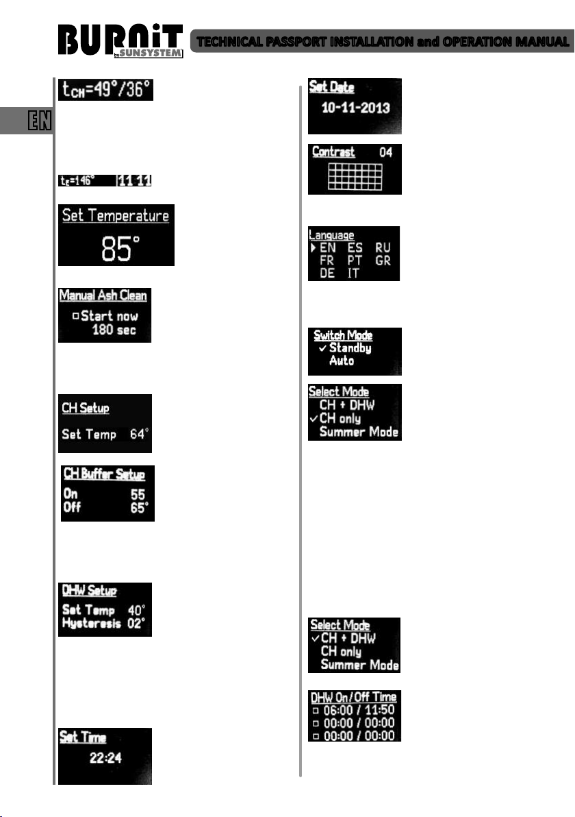
TECHNICAL PASSPORT INSTALLATION and OPERATION MANUAL
Parameter tСН indicates the
temperature at upper and boom part of the buer
tank.
EN
This screen is acve only when has been selected the
menu opon for boiler control according to buer
temperature.
set the follow parameters:
“Navigaon arrow Up” and “Navigaon arrow
Down”. Aer entering the correct value press buon
“Enter”.
. From this menu you can
scheme (with buer tank included) is selected,
whereas the two sensors reading these temperatures
are mounted in the upper, respecvely lower part of
the buer tank (cf. boiler connecon schemes).
down and using the Enter buon you can change the
parameters. You can adjust the maximum domesc
hot water temperature inside the storage tank, as
well as the switch-on hysteresis for the circulaon
pump aer a drop of DHW temperature inside the
storage tank.
value of instantaneous
Parameter tE indicates exhaust
gases temperature.
Set maximum
temperature of the boiler
through navigaon
arrows. Press buon F
and hold for 3 seconds to
Possibility for forced turn on of
ash and soot transport screw.
Time seng of screw
operaon. To set start and
operang me use buons
Use this menu to adjust switch-
on temperature of central
heang pump.
preset buer tank circulaon
pump switch-on and switcho temperatures provided
such heang installaon
From this menu you can adjust
the maximum temperature in
the domesc hot water storage
tank, whereas by navigang
from the arrow keys up and
Use UP and DOWN arrow keys
in Set Time menu to set the
unit’s built-in mer/clock.
Use UP and DOWN arrow keys
in Set Date menu to set the
date.
Use UP and DOWN arrow keys
in Contrast menu to adjust the
LCD display backlight level.
Conrm sengs by shiing to
next submenu through a single
pressing of the funconal key F.
Use this menu to choose the
language of the controller.
Choose a language by pressing
navigation arrows and button
“Enter”.
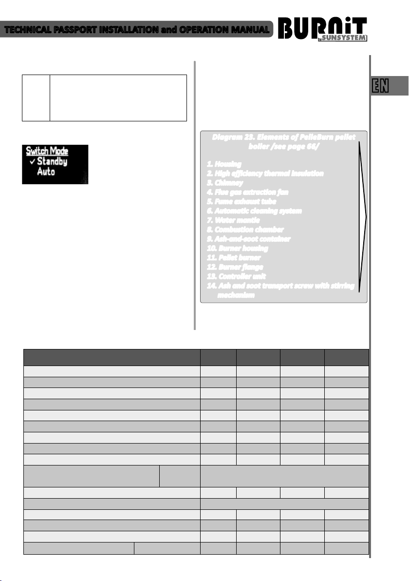
10.2.2. Burner start-up „Switch mode“
Burner start-up. Aer pressing
the “F” buon and using the
navigaon arrows, the “Auto”
or „Standby” menu is selected.
Set the priority mode of the
burner through “navigaon
arrows.”
- CH + DHW – Both pumps /CH-central heang
pump and DHW – domesc hot water pump /are
acve.
- CH only – In this mode of operaon the only acve
pump is the CH circulaon pump for the heang
installaon (CH pump). In this mode, the boiler
can be managed via a room thermostat or be
temperature-controlled by the temperature inside
the connected buer tank to it (depending on the
connecon scheme)
- Summer Mode – Boiler works for heang of
domesc hot water only.
If you have selected the (CH +
DHW) opon, upon
conrmaon of command via
the F buon you may navigate
to the next screen.
From this menu you can set up
and adjust DHW pump acvity
periods. Use the arrow keys to
set me (HH:MM). Use “Enter”
buon to checkmark desired
me period opon. If no opon is check-marked, the
controller will maintain DHW temperature as a
16
TECHNICAL PASSPORT INSTALLATION and OPERATION MANUAL
priority. Only when its preset value is reached, the CH
circulaon pump will start.
Important – The use of “External room
thermostat for the burner” option
(Thermostat) is active only if option is
selected (CH Priority – priority of central
heating installation pump).
10.2.3. Burner shut-down „Standby“
Pressing the “F” buon will
take you to the main menu and
by using the navigaon arrows
menu and conrm the selecon by pressing “F”. The
burner goes into exnguishing mode. Set the
temperature to start heang pump.
11. MOUNTING OF FUEL HOPPER FH 500
Fuel hopper FH 500 has a capacity of 500 liters
pellets. Its design allowing installation by choice on
either side of boiler. An important condition is to be
leveled. Before loading the pellets, make sure that
the hopper is clean. Empty the container for pellet
powder and dust.
Fuel hopper hatch-cover must be closed during
operation. Detailed description for the assembly of
a fuel hopper FH 500 will find the User manual for
assembling the fuel hopper FH 500.
you can select the “Standby”
12. WARRANTY TERMS
The warranty terms are described in the Service
booklet included in the supply.
EN
13. TECHNICAL FEATURES
13.1. Technical features of PelleBurn pellet boiler
13.1.1. Elements of PelleBurn pellet boiler
Diagram 23. Elements of PelleBurn pellet
boiler /see page 66/
1. Housing
2. High efficiency thermal insulation
3. Chimney
4. Flue gas extraction fan
5. Fume exhaust tube
6. Automatic cleaning system
7. Water mantle
8. Combustion chamber
9. Ash-and-soot container
10. Burner housing
11. Pellet burner
12. Burner flange
13. Controller unit
14. Ash and soot transport screw with stirring
mechanism
13.1.2. Technical parameters of PelleBurn pellet boiler
PelleBurn 15 PelleBurn 25 PelleBurn 40
Nominal heat output
Min / Max heat output
Height H
Width L / Depth D
Mantle volume
Combuson chamber volume
Combuson chamber resistance
Water side pressure drop (ΔT = 20°C) Pa/mH2O 480/0,048 850/0,085 1350/0,135
Required chimney draught
Insulaon
Electric power supply
Recommended fuel
Operang temperature range
Operang pressure
Pellet burner Pell Power kW 5÷15 8÷25 10÷40
Boiler
Doors
Weight
kW 15 25 40
kW 5÷15 8÷25 10÷40
mm 1290 1430 1700
mm 640/1120 640/1120 700/1120
l 55 70 101
l 43 53 73
Pa/mbar 10/0,10 11/0,11 12/0,12
Pa 10÷20 10÷20 10÷20
100 mm high-eciency thermal wool
lined with aluminum foil
20 mm high-eciency black veil rockwood
V/Hz/A 230/50/10 230/50/10 230/50/10
wood-pellets, diameter 6÷8 mm
°C 65-85 65-85 65-85
bar 3 3 3
kg 220 240 358
17
TECHNICAL PASSPORT INSTALLATION and OPERATION MANUAL
EN
Pellet fuel hopper
Cold water inlet
Hot water outlet
Safety line sleeve
Air vent
Cleaning opening
Combuson viewer
Boiler ue gas extracon fan
Burner air-feed fan
Automac cleaning device
Cleaning device motor
Burner ange
Ash and soot transport motor
Ash-and-soot container
Control unit
L 500 500 500
A, mm R ¾’’/100 R ¾’’/100 R ¾’’/100
B, mm R ¾’’/980 R ¾’’/1120 R ¾’’/1417
К
I
F,
Flue
J,
O, mm 140/300 140/300 140/300
Drain
E
V
W1,
mm
W2,
mm
P, mm 950 1090 1390
M
Z
N, mm 170 170 170
Т
U
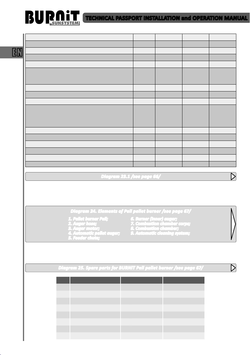
Diagram 23.1 /see page 66/
13.2. Technical features of Pell pellet burner
13.2.1. Elements of Pell pellet burner
ø
mm
mm
133
1280
320
1220
510
133
1480
320
1385
510
150
1700
350
1665
565
Diagram 24. Elements of Pell pellet burner /see page 67/
1. Pellet burner Pell;
2. Auger hose;
3. Auger motor;
4. Automatic pellet auger;
6. Burner (inner) auger;
7. Combustion chamber corps;
8. Combustion chamber;
9. Automatic cleaning system;
5. Feeder chute;
13.2.2. Spare parts for Pell pellet burner
Diagram 25. Spare parts for BURNiT Pell pellet burner /see page 67/
№ Part Number Model PEll 25 Model PEll 40
1 82801300000002 х
1 82801300000003 х
2 82801300000010 Х
2 82801300000011 х
3 89801300000006 х
3 89801300000024 Х
4 89800000000005 Х Х
5 89801381000001 Х
18
TECHNICAL PASSPORT INSTALLATION and OPERATION MANUAL
5 89801381000002 Х
6 78801100000001 Х Х
7 32800032000001 Х Х
8 89080000000006 Х Х
9 89801200000006 Х Х
10 89800000000004 Х Х
11 32590000000092 Х Х
12 89080000000007 Х Х
13 32640000000004 Х
13 32640000000003 Х
14 32800000000006 x(C130) x(C130)
13.3. Technical features of fuel hoper FH 500
13.3.1. Elements of fuel hopper FH 500
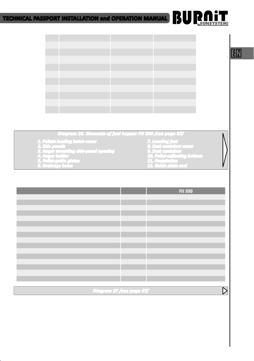
Diagram 26. Elements of fuel hopper FH 500 /see page 67/
1. Pellets loading hatch-cover
2. Side panels
3. Auger mounting side-panel opening
4. Auger holder
5. Pellet-guide plates
6. Drainage holes
13.3.2. Technical parameters of fuel hopper FH 500
Capacity l 500
Max/Min wood pellets load ø, 6÷8 mm kg 280÷300 / 15
Height H mm 1260
Width L / Depth D mm 772 / 730
Foundaon B, mm 53
Auger mounng opening C, ø mm 76
Auger holder E
Pellet-load hatch F, mm 400 / 772
Hinges G
Drainage holes J
Dust container X
Inclinaon of guide plates P 45°
Pellet-colecng boom R, mm 300 / 300
Leveling feet Z
Guide plate seal
Weight kg 82
7. Leveling feet
8. Dust container cover
9. Dust container
10. Pellet-collecting bottom
11. Foundation
12. Guide plate seal
EN
FH 500
Diagram 27 /see page 67/
19
TECHNICAL PASSPORT INSTALLATION and OPERATION MANUAL
14. RECYCLING
Submit all packaging material for recycling according
to the local regulations and requirements.
At the end of life cycle of each product its
EN
components are due to be disposed of in conformity
with regulatory prescriptions.
Obsolete equipment shall be collected separately
from other recyclable waste containing materials
with adverse effect on health and environment.
According to Directive 2002/96/EC regarding
electrical and electronic equipment waste, disposal
thereof is required separately from the normal flow
of solid household waste.
Expired appliances must be collected separately
from other recyclable waste containing substances
hazardous to health and environment. Both metal
and non-metal parts are sold out to licensed
organizations for recyclable metal or non-metal
waste collection. In any case they should not be
treated as household waste.
20

TECHNISCHES DATENBLATT MONTAGE- und BEDIENUNGSANLEITUNG
INHALT
1. ERLÄUTERUNG DER SYMBOLEN UND SICHERHEITSHINWEISE .............................................................. 22
1.1. Erläuterung der Symbolen .................................................................................................................... 22
1.2. Hinweise für den Raum der der Kesselaufstellung ................................................................................ 22
1.2.1. Hinweise für den Installateur ................................................................................................................ 22
1.2.2. Hinweise für Anlagebenutzer ................................................................................................................ 22
1.2.3. Mindestabstände bei der Montage und Brennbarkeit der Baumaterialien .. ........................................ 23
2. BESCHREIBUNG VOM ERZEUGNIS ..................................................................................................... 23
2.1. Konstruktion des Pelletkessels .............................................................................................................. 23
2.2. Konstruktion von Pelletbrenner ............................................................................................................ 24
2.3. Sicherheitsschutz des Pelletkessels und des Brenners ......................................................................... 24
2.4. Schneckeneinrichtungen für Beförderung von Pellets .......................................................................... 25
2.5. Einrichtungen für Pelletsbunker FH 500 ................................................................................................ 25
3. BRENNSTOFFE ....................................................................................................................................... 25
4. BEFÖRDERUNG VON KESSEL ................................................................................................................. 26
5. KESSELLIEFERUNG ............................................................................................................................... 27
6. MONTAGE VOM HEIZKESSEL ............................................................................................................. 27
7. MONTAGE DES HEIZKESSELS .............................................................................................................. 27
7.1. Anschluss des Kessels an einen Schornstein ......................................................................................... 27
7.2. Anschluss des Kessels an Bunker und Schnecke .................................................................................... 28
7.3. Anschluss des Kessels und Brenner an das Stromnetz .......................................................................... 28
7.4. Kessel - Anschluss an das Heizsystem ................................................................................................... 29
7.5. Schema Zusammenfügung .................................................................................................................... 31
8. FÜLLEN DER HEIZANLAGE ................................................................................................................... 31
9. NUTZUNG VOM KESSEL ......................................................................................................................... 31
DE
10. MIKROPROZESSORSTEUERUNG ............................................................................................................ 34
10.1. Ansicht vom Kontroller. Erläuterung der Druckknöpfe und der Indikatoren ........................................ 34
10.2. Benutzermenü ..................................................................................................................................... 35
11. MONTAGE VON PELLETBUNKER ........................................................................................................... 37
12. GARANTIEBEDINGUNGEN ..................................................................................................................... 37
13. TECHNISCHE CHARATERISTIKEN ............................................................................................................ 37
13.1. Technische Charakteristiken des Pelletskessels PelleFlux .................................................................... 37
13.2. Technische Parameter für Pelletbrenner BioFlux ........................................................................................ 38
13.3. Technische Charakteristiken des Pelletsbunker FH500 ......................................................................... 39
14. RECYCLING UND AUSWURF ............................................................................................................... 39
ANHANG - Diagramme .................................................................................................................................... 59
21

TECHNISCHER DATENBLATT MONTAGE- und BEDIENUNGSANLEITUNG
1. ERLÄUTERUNG DER SYMBOLE UND
SICHERHEITSHINWEISE
1.1. Erläuterung der Symbole
ACHTUNG! – Wichtiger Hinweis oder
Warnung, die die Sicherheitsbedingungen bei
Montage, Installation und Bedienung des
Pelletkessels betrifft.
GEFAHR! – wegen Beschädigung oder
DE
falscher Bedienung besteht Gefahr für Leib
und Leben von Menschen und Tieren
FEUERGEFAHR! – wegen Beschädigung,
falscher Montage und Bedienung besteht
Feurgefahr.
INFORMATION – das Zeichen weist auf den
Teil der Anleitung, die die genaue Einstellung
und die nötige Parameter des Erzeugniss
betrifft, damit Sie das gewünschte Ergebnis erzielen
können.
1.2. Hinweise auf den Raum der Kesselaufstellung
Die vorliegende Anleitung enthält wichtige
Information für eine sichere und richtige Montage,
Inbetriebnahme, störungsfreie Bedienung und
Instandhaltung des Pelletkessels.
Der Pelletkessel darf für Heizung von Räumen benutzt
werden, nur nach der Art und Weise, beschrieben in
der vorliegenden Anleitung.
Berücksichtigen Sie die Daten für den Typ des Kessels
auf dem Herstellungssticker und die technischen
daten, um die richtige Nutzung des Erzeugnises zu
versichern.
1.2.1. Hinweise für den Installateur
Bei Installierung und Nutzung müssen die
Vorschriften und Normen des entsprechenden
Landes eingehalten werden:
• die örtliche Bauvorschriften für Montage,
Luftversorgung und Abgasentsorgung, sowie der
Anschluss an einen Schornstein
• die Vorschriften und Normen für die
Sicherheitsausrüstung des Heizsystems.
• Es wird vorgeschrieben, dass ein Rauchmelder im
Kesselraum eingebracht wird.
Der autorisierte Installateur / Fachmann
ist verpflichtet den Anlagenbenutzer über
alle Wichtige Besonderheiten bezüglich
der Anlagennutzung und Reinigung
aufzuklären.
Es ist zwingend notwendig, dass eine
Notfallstromversorgung /Generator mit
der notwendigen Leistung/ mitaufgestellt
wird (siehe. Tabelle 1).
ACHTUNG! Die Montage und die
Einstellung des Kessels darf nur von
einem autorisiertem Service oder einem
autorisiertem Fachmann, bei Einhaltung der
Sicherheitsanleitungen und Arbeitsregeln,
ausgeführt werden.
VERGIFTUNGS- UND ERSTICKUNGSGEFAHR.
Der geringere Luftzutritt im Kesselraum
kann eine gefährliche Abgasausströmung
Während der Verbrennung des Kessels
verursachen.
- Vergewissern Sie sich, daß die Öffnungen
für Eintritts- und Abgasluft nicht verstopft
oder geschlossen sind.
- Wenn die Beschädigungen nicht
sofort beseitigt werden können, darf
der Pelletkessel nicht benutzt werden.
- Machen Sie eine schriftliche Anweisung
für den Benutzer der Anlage bezüglich der
Beschädigung und der davon ausgehende
Gefahr.
FEUERGEFAHR wegen brennbare
Materialien oder Flüssigkeiten.
- Brennbare Materialien oder Flüssigkeiten
dürfen in unmittelbarer Nähe des
!
Pelletkessels gesetzt werden.
- Weisen Sie dem Benutzer der Anlage für
die mindesten Abstände bezüglich der
umstehenden Gägenstände an.
Benutzen Sie nur originale Ersatzteile
i
Energieverbrauch des Kessels
Stromversorgung bei maximaler Leistung 780 W
Stromversorgung bei Nennleistung 80 W
Stromversorgung bei minimaler Leistung 60 W
1.2.2. Hinweise für Anlagebenutzer
VERGIFTUNGS UND EXPLOSIONSGEFAHR.
- Benutzen Sie keine Abfälle, Kunststoffe,
Naphthalin oder Flüssigkeiten – Benzin,
Motorenöl zum Zünden des Brenners.
Benutzen Sie nur der, in vorliegender
Anleitung, vorgegebenen Brennstoff.
$
Anderenfalls entfällen die
Garantieansprüche.
-Bei Explosions-, Entzündungs- oder
Abgasausströmungsgefahr im Kesselraum,
schalten Sie den Brenner und Kessel aus.
Tabelle 1.
22

TECHNISCHER DATENBLATT MONTAGE- und BEDIENUNGSANLEITUNG
Es ist zwingend notwendig, dass eine
Notfallstromversorgung /Generator mit
der notwendigen Leistung/ mitaufgestellt
wird (siehe. Tabelle 1).
Der autorisierte Installateur / Fachmann
ist verpflichtet den Anlagenbenutzer über
alle Wichtigen Besonderheiten bezüglich
der Anlagennutzung und Reinigung
aufzuklären.
ACHTUNG! Verletzungsgefahr/ Störung
an der Anlage wegen inkompetenter
Bedienung
- Der Pelletkessel darf nur von Personen
bedient werden, die sich mit der
Gebrauchsanweisungen bekannt gemacht
haben
- Als Benutzer dürfen Sie den Kessel nur
Allgemeine Sicherheitsregeln, die vom Verbraucher
durchzuführen sind:
- Benutzen Sie den Pelletkessel nur mit dem
- Kontrollieren Sie regelmäßig den Kesselraum.
- Verwenden Sie keine Flüssigkeiten bei der Zündung,
- Reinigen Sie die Oberfläche des Kessels nur mit
- Stellen Sie keine brennbare Gegenstände auf dem
- Bewahren Sie keine brennbaren Materialien im
- Es wird vorgeschrieben, dass die Anweisungen
- Veränderungen in der Kesselkonstruktion seitens
- Der Verbraucher darf den Kontakt von Strom-
- Die vorliegende Anleitung ist sorgfältig
in Betrieb nehmen, die Temperatur des
Kessels regeln, den Kessel ausschalten und
reinigen.
- Der Zugang von Kindern ist im Raum mit
laufendem Kessen ohne Aufsicht verboten.
empfohlenen Brennstoff,
sowie auch für die Steugerung der Kesselleistung
nichtbrennbaren Mitteln.
Kessel oder in seiner Nähe (sieh Schema 1 für die
Mindestabstände)
Kesselraum auf.
für Anschliessen des Brenners an das Stromnetz,
sowieauch an die Peripheriegeräte strikt eingehalten
werden müssen.
des Benutzers können zu Beschädigung des Gerätes
oder Verletzung führen.
oder Sensorleiter zu Kesselteilen, die eine
Oberflächentemperatur von 70°C übersteigen nicht
zulassen.
aufzubewahren.
ACHTUNG! Heiße Oberflächen!
Es besteht die Verbrennungsgefahr bei
Berührung des laufenden Kessels. Die
Verkleidung des Brenners, der Brennerkörper
und der Brennerflansch sind warme
Oberflächen während der Brennerarbeit.
Es ist absolut verboten, die Revisionstüren
des Kessels bei laufendem Brenner geöffnet
zu werden.
Achten Sie bei der Berührung des Okulars
für Beobachtung des Brennungsvorgangs. Er
kann heiß sein.
1.2.3. Mindestabstand bei Montage und
Brennbarkeit von Baumaterialien
Es ist möglich, dass in Ihrem Land andere
Mindestabstände als die unten vermerkten gelten.
Bitte, konsultieren Sie sich mit Ihrem Instalateur.
Der Mindestabstand des Brenners, des Heizkessels
oder des Abgasrohres zu Gegenständen und Wänden
muss mindestens 200 mm sein.
Tabelle 2. Entzündbarkeit der Baumaterialien
Klasse А -
feuerbeständig
Klasse В
– schwer
entflammbare
Klasse С1/С2
mittelbrennbare
Klasse С3 leicht
brennbare
Schema 1. Empfehlenswerter Abstand des
Pelletkessels zu den Wänden /siehe Seite 59/
Zwecks allgemeiner Sicherheit empfehlen wir, dass
der Kessel auf einen Fundament aus Material Klasse
A, aufgestellt wird. Sieh Tabelle 2.
2. BESCHREIBUNG VOM ERZEUGNIS
Der hocheffektive Pelletkessel ist für die Heizung
mittels Holzpellets bestimmt. Der speziell
konstruierte Wassermantel bedeckt gänzlich die
Brennkammer zwecks Erhöhung der Effektivität und
des Wirkungsgrades bis 91%.
Der Kessel ist gemäß europäischen Normen EN 3035, Klasse 5 getestet.
Der Satz enthält Kessel mit Pelletbrenner,
Pelletförderschnecke und Bunker (optional) für die
Brennstofflagerung.
2.1. Konstruktion des Pelletkessels.
Der Kesselkörper hat eine zylindrische Form, und ist
23
Stein, Ziegel, keramische Fliesen,
gebrannter Lehm, Mörtel, Putz
ohne organische Zusätze
Platten Gipskarton, basaltiger Filz,
Glasfaser, AKUMIN, Izomin, Rajolit,
Lignos, Velox, Heraklit.
Holz Buche, Eiche
Holz Nadelbäume, aufgeschichtetes
Holz
Asphalt, Karton, Zellulose, Teer,
Holzfaser, Kork, Polyurethan,
Polyethylen.
DE

TECHNISCHER DATENBLATT MONTAGE- und BEDIENUNGSANLEITUNG
aus hochwertigem Kesselstahl mit gebaut, 4 mm für
die Brennkammer und 3 mm für den Wassermantel.
• Ökologisch. Die Holzpellets, die für den
Verbrennungsvorgang benutzt werden, sind aus
nachwachsenden Rohstoffen mit minimaler Menge
schädlicher Emissionen hergestellt worden.
• Automatisiert. Dank des vervollkommenen
Wirkungsalgorithmus und die Fähigkeit Vielzahl
von Parameter zu kontrollieren, kann er
DE
präzis an das Bedürfnis des Heizungssystems
angepasst werden, wobei die Effizienz erhöht
und der Brennstoffverbrauch gesenkt wird. Der
Hauptsteuerungsblock, der sich befindet, steuert
den ganzen Heizungsvorgang.
1) automatisierte Zündung und Pelletvorschub;
2) Rauch – Lüfter am Ausgang der Abgase, sorgt für
stabile Arbeit des Kessels;
3) Selbsreinigungsfunktion des Kessels und des
Brenners;
4) Steuerung der Pumpe für die Heizungsanlage;
5) Steuerung des Außenraumthermostat ;
6) Steuerung der Pumpe für heißes Brauchwasser;
7) Abgassensor/Abgasfühler;
• Effektiv. Der Kesselkörper ist durch eine
Hochtemperaturwatte mit Dicke von 100 mm
isoliert. Durch die Steuerung des Brennvorgangs
und das zylindrische Design des Körpers, erreicht
der Kessel eine Effizienz von bis zu 91% und schont
die Umwelt mit besonders niedrigen Emissionen.
2.2. Konstruktion von Pelletbrenner
Schema 2. K on s tr uk t io n v o n P e ll et b re n ne r
Der Pelletbrenner, montiert zum Kessel,
besteht aus hochwertigemrostfreiem Stahl,
Temperaturbeständig bis 1150°С. Er besteht aus
dem Rohr der Brennkammer und einem Außenrohr
mit Blechverkleidung. Unter der Längsverkleidung
sind Einströmkammerr, Heizelement für Entflammen
vom Brennstoff, Lüfter, und elektrische Versorgung.
Im oberen Teil des Brenners ist das Versorgungsrohr,
welches mit der Pelletschnecke zusammengefügt
wird. Die Brennkammer des Brenners besteht aus
zwei Rohren:
Glutbeständiges Stahlrohr im inneren Teil des
Brenners, mit Öffnungen für Lufteintritt auf der
ganzen Länge, Öffnung für Heißluft vom Heizelement
für Entzündung des Brennstoffes, Öffnung für
Flammensensor.
Funktionen:
/siehe Seite 59/
Außenrohr aus rostfreiem Stahl. Zwischen den
beiden Rohren gibt es Bereich für die freie
Luftzirkulation, deie für die Kühlung, sowie auch
für die Sauerstoffübertragung in der Brennkammer
erforderlich ist.
Das Versorgungsrohr kann sich in 360° umdrehen,
so daß das Rohr eine passende Position für die
Zusammenfügung zur Bunkerschnecke hat.
Die anderen Elemente vom Brenner sind:
· Innere Schnecke
· Trockenes kontaktloses Heizelement, das die
Brennstoffzündung sichert.
· Pneumatische Reinigungssystem der Brennkammer
· Stufenlos einstellbare Druckvenlator (0% to 100 %)
· Teleskop-mechanismus der Brenner
2.3. Sicherheitsschutz des Pelletkessels und des
Brenners.
Die Sicherheitselemente garantieren den sicheren
Kesselbetrieb. Der Brennvorgang wird elektronisch
kontrolliert durch eine Schrittweise Modulierung
des Brennerbetriebs in Übereinstimmung mit dem
Energiebedarf und steht immer in einer optimalen
Betriebart. Ein selbstständiger Not – Thermostat
STB/Sicherheitstemperaturbegrenzer/ stoppt
den Brenner und beendet die Luftzufuhr in der
Brennkammer, falls die angegebene Temperatur
überstiegen wird.
· Das gebogene Versorgungsrohr und das flexible
Versorgungsrohr für Anbindung Schnecke – Bunker.
Die geometrische Form des Versorgungsrohres des
Brenners erlaubt nicht, dass ein Rückbrand vom
Brenner zum Pelletbunker entsteht. Zusätzlich
ist auch flexibles Rohr montiert, welches bei
Temperatur über 80°C schmilzt und erlaubt nicht,
daß das Feuer im Bunker eindringt.
· Thermostatischer Schutz (80°C) Der
thermostatische Schutz ist am Versorgungsrohr
montiert. Bei Erreichen einer Temperatur von 80°C
auf der Oberfläche des Versorgungsrohres stoppt
die Steuerung den Pelletvorschub zum Brenner und
signalisiert eine Havarie (BB Alarm).
• Schutzvorrichtung. Im Falle einer
Elektrobeschädigung im Brennersystem
(Kurzschluss, Hochstrom u.a.). Die Überbelastung
wird von einer elektrischen Schutzvorrichtung
übernommen, die im Hauptsteuerungsblock des
Brenners montiert ist. (10 А).
• innovative Steuerung: Im Falle eines Stromausfalls
werden alle eingestellte Parameter im Speicher
der Steuerung gespeichert. Beim nächsten Restart
des Brenners setzt die Programmausführung fort,
24

TECHNISCHER DATENBLATT MONTAGE- und BEDIENUNGSANLEITUNG
genau dort wo die Elektroversorgung ausgefallen
ist.
2.4 Schneckeneinrichtungen für Beförderung von
Pellets
Die Schnecke für Pelletsbeförderung besteht aus:
Hauptrohr, flexibles Rohr, Motor, Transportband für
Pelletstransport.
Schema 3. Sc hnec keei nric htun g
/siehe Seite 59/
2.5 Einrichtungen für Pelletsbunker FH 500
Schema 4. Einrichtungen für Pelletsbunker
Der Pelletbunker hat den Zweck, die Kessel zu
bedienen, die mit Pelletbrennstoff funktionieren. Die
Montage ist wählbar auf einer der beiden Seiten des
Kessels. Er ist aus kaltem Walzblech, mit PVC Anstrich,
hergestellt. Bequemer Deckel zur Pelletbefüllung. Die
Pelletnutzung im Bunker folgt der Reihenfolge des
Vorschubes. Dank der Schraubfüße, kann der Bunker
präzis nivelliert werden. Die Dränageöffnungen und
der im Fundament eingebauten Behälter erleichtert
die Bunkerreinigung, ohne seine Entleerung.
Das Volumen des Bunkers wird auf Basis Tages- oder
Wochenbrennstoffaufwand des Brenners bestimmt.
Inhalt von 500 Liter Nutzvolumen erlaubt die Ladung
von 280-300 Kg Pellets ø 6 mm und Nachladung
des Bunkers mit Brennstoff einmal wöchentlich (bei
Brenner mit Leistung bis 40 kW).
Alle Pellets sind Biomasse, hergestellt aus normalen
niedrig wachsenden Pflanzen und Bäumen.
Die Pellets bestehen meist aus Sägemehl und
zermahlener Späne hergestellt, welche bei der
Herstellung von Holzsträume, Möbel und andere
Erzeugnisse abfallen. Das Holz ist die reicheste
Rohstoffquelle. Das Rohmaterial wir bei hohem
Druck und Temperatur verarbeitet und wird an
kleine Pellets mit zylindrischer Form gepresst. Für
die Produktherstellung kann man weiches Holz (z.
B. Nadelholz, Kiefer), hartes Holz (Eiche), sowie auch
Recycling - Holzabfälle benutzen. Die Holzpellets
werden in Mühlen oder in Werkstätten für Holzpellets
hergestellt.
• Komfort bei der Aufbewahrung. Die Pelletssäcke
können
Keller, Serviceraum oder Schuppen gelagert
FH 500 /siehe Seite 59/
3. BRENNSTOFFE
Vorteile der Holzpellets:
auf einer kleinen Fläche in trockene Garage,
werden.
• Leichte Aufladung. In den meisten Fällen wird
die Bunkeraufladung nur einmal in der Woche
ausgeführt– es hängt von dem Bunkerinhalt ab.
• Bessere Regulierung der Brennstoffmenge. Die
kleine Größe der Pellets erlaubt den präzisen
Brennstoffvorschub. Des Weiteren reguliert man
den Luftvorschub für die optimale Effektivität der
Brennung leichter, weil die Brennstoffmenge in der
Brennkammer konstant und voraussehbar ist.
• Brennstoffeffektivität. Die hohe Effektivität der
Verbrennung ist auch von dem gleichmäßigen
niedrigen Feuchtigkeitsgehalt der Pellets abhängig.
(ständig unter 10% im Vergleich zu 20% bis 60%
Feuchtigkeitsgehalt bei den gesägten Hölzern). Die
niedrige Feuchtigkeit, die kontrollierten Portionen
Brennstoff und die präzise regulierte Luft bedeuten
hohe Effektivität beim Brennen und sehr niedriges
Niveau von Kohlenmonoxid in den verbrannten
Gasen.
Verlangen Sie bei Pelletseinkauf eine
Übereinstimmungserklärung und Zertifikat
vom akkreditierten Labor und vergewissern
Sie sich, daß der Brennstoff den in der
Anleitung vermerkten Anforderungen
entspricht. Bei Einkauf einer großen Menge
Pellets (z.B für eine Heizperiode nötig)
verlangen Sie vom Ihren Lieferanten präzise
und korrekt zu informieren zu werden, wie
die Pellets aufzubewahren sind.
Wir empfehlen Pellets mit Durchmesser 6-8 mm,
Dichte 600-750 kg/m³ Kaloriengehalt 4,7-5,5 kWh/
kg. Staubgehalt – nicht mehr als 1% und Feuchtigkeit
bis 8%, EN 14961-2:2011.
Die optimale Dichte der Pellets, welche ihre Qualität
garantieren, ist im Bereich 605 - 700 kg. /m³.
Die Pelletsfeuchtigkeit darf nicht mehr als 10% sein.
Vergewissern Sie sich, daß Ihr Brennstoff auf einem
trockenen und gut belüfteten Platz gelagert ist.
Die optimale Menge Staub in Pellets ist ≤ 1%. Davon
wird auch der selteneren Brennerreinigung bedingt.
In der folgenden Tabelle sind die Parameter
angegeben, welche berücksichtigt werden sollen,
wenn Sie den Brennstoff für Ihren Brenner auswählen.
25
DE

TECHNISCHER DATENBLATT MONTAGE- und BEDIENUNGSANLEITUNG
Tabelle 3. Europäisches Zertifikat für Holzpellets
Parameter Masseinheiten ENplus-A1 ENplus-A2 EN-B
Durchmesser Mm
Länge Mm 15 ≤ L ≤ 40
Schütt- Dichte kg / m
2
6 (± 1)
8 (± 1)
1)
≥ 600 ≥ 600 ≥ 600
Kaloriengehalt MJ / kg ≥ 16,5-19 ≥ 16,3-19 ≥ 16,0-19
Feuchtigkeit Ма .-% ≤ 10 ≤ 10 ≤ 10
DE
Staub Ма .-% ≤ 1
Mechanische Stärke Ма .-% ≥ 97,5
Asche Ма .-%
2)
3)
4)
≤ 0,7 ≤ 1,5 ≤ 3,5
Schmelzpunkt der Asche °C ≥ 1200 ≥ 1100 Chlorgehalt Ма .-%
Schwefelgehalt Ма .-%
Stickstoffgehalt Ма .-%
Kupfergehalt mg / kg
Chromgehalt mg / kg
Arsengehalt mg / kg
Kadmiumgehalt mg / kg
Quecksilbergehalt mg / kg
Bleigehalt mg / kg
Nickelgehalt mg / kg
Zinkgehalt mg / kg
1)
nicht mehr als 1% von Pellets darf länger als 40 mm sein,maximale Länge 45 mm;
2)
trockene Masse;
3)
Teilchen<3.15 mm, feine Staubteilchen, bevor die Ware übergeben ist;
4)
für Messungen mit Lignotester grenzen-zulässige Wert ≥ 97,7 Gewichts- %.
2)
2)
2)
2)
2)
2)
2)
2)
2)
2)
2)
≤ 0,02 ≤ 0,02 ≤ 0,03
≤ 0,03 ≤ 0,03 ≤ 0,04
≤ 0,3 ≤ 0,3 ≤ 1,0
≤ 10 ≤ 10 ≤ 10
≤ 10 ≤ 10 ≤ 10
≤ 1,0 ≤ 1,0 ≤ 1,0
≤ 0,5 ≤ 0,5 ≤ 0,5
≤ 0,1 ≤ 0,1 ≤ 0,1
≤ 10 ≤ 10 ≤ 10
≤ 10 ≤ 10 ≤ 10
≤ 100 ≤ 100 ≤ 100
6 (± 1)
8 (± 1)
15 ≤ L ≤ 40
3)
≤ 1
≥ 97,5
1)
4)
6 (± 1)
8 (± 1)
15 ≤ L ≤ 40
3)
≤ 1
≥ 96,5
1)
4)
4. BEFÖRDERUNG VON KESSEL
Bei Verladung, Beförderung und Ausladung des
Erzeugnises sollen passende Sicherheitsmittel
benutzt werden, in Übereinstimmung mit der
Richtlinie 2006/42/СЕ.
Die Beförderung eines Erzeugniss mit Gewicht über
30 Kg, soll man einen Palettenkarren, Motorkarren
oder andere Stößel benutzen.
Das Erzeugnis muss in seiner originalen Verpackung
sein und die Hinweise auf dem Schild sollen
eingehalten werden – das Erzeugnis muss von
schlechter Wetterlage (Schnee, Regen und Staub),
von Erschütterungen, Stöße und andere Taten, die
eine Beschädigung verursachen können, geschützt
werden.
Der Kessel ist stabil mittels Ausbauelementen zu
einer Holzpalette befestigt.
Wichtig: Bei der Kesselinstallierung
muss die Holzpalette, auf der der
Kessel liegt entfernt werden, indem die
Bolzenverbindungen mit Hilfe einem
Schlüssel S13 abgeschraubt werden.
Falls Sie einen Mangel bei einer Komponente
feststellen (Lüfter oder Motoreinrichtung) oder
Mangel bei einem hochtechnisiertem Element z.B.
nicht funktioniertendem Kontroller, verbinden Sie
sich mit dem nahstehenden bevollmächtigten Service
für Reparaturen und Wartung.
Schema 5. Bezeichnungen Ausmaßdimensionen
/siehe Seite 59/
26

TECHNISCHER DATENBLATT MONTAGE- und BEDIENUNGSANLEITUNG
PellFlux 15 25 40
Kesselkörper, Brenner und Palette
A1, mm
Schnecke, Karton
A2, mm
Bunker, Karton
A3, mm
Kesselkörper, Brenner und Palette
B1, mm
Schnecke, Karton
B2, mm
Bunker, Karton
B3, mm
Kesselkörper, Brenner und Palette
C, mm
Kesselkörper, Brenner und Palette
D1, mm
Schnecke, Karton
D2, mm
Bunker, Karton
D3, mm
Kesselkörper, Brenner und Palette 185 200 325
Weight,
Schnecke, Karton 8 8 8
kg
Bunker, Karton 48 48 48
710 710 810
120 120 120
840 840 840
1100 1100 1320
260 260 260
810 810 810
125 125 125
1430 1630 1775
1700 1700 1700
1220 1220 1220
DE
5. KESSELLIEFERUNG
· Prüfen Sie bei der Lieferung die Ganzheit der
Verpackung.
· Prüfen Sie, ob Sie alle Komponenten erhalten
haben.
· Die Kessellieferung enthalten:
1) Kessel mit Brenner
2) Schnecke
3) Bunker FH 500 (optional)
4) Sicherheitsventil 3 bar .
5) Feuerhaken
6) Technisches Datenblatt. Montage- und
Betriebsanleitung
7) Servicekarte und Garantieschein
Falls Sie eine fehlende Komponente entdecken,
wenden Sie sich an Ihren Lieferanten.
6. MONTAGE VOM HEIZKESSEL
Die Montage, die Installierung und die
Einstellung des Kessels soll von einem zu
diesem Zweck autorisierten Fachmann
ausgeführt werden.
Der Instalateur ist verpflichtet, den
Benutzer über die Mindestabstände zu
brennbare Materialien und Flüssigkeiten
aufklären.
- Der Kesselraum muss gegen Frost geschützt werden;
- Im Kesselraum muss ständige Zuluft gesichert
werden, die für das Brennen erforderlich ist;
- die Kesseln dürfen nicht in bewohnbaren Räumen
aufgestellt werden;
- Jeder Kesselraum muss eine entsprechend der
Kesselleistung berechnete Ventilationsöffnung
haben. Die Öffnung muss mit einem Netz oder mit
einem Gitter geschützt werden.
Die Größe der Ventilationsöffnung wird nach der
folgenden Formel berechnet:
Anforderungen
А=6,02*Q - wo:
А – die Öffnungfläche in сm2,
Q – Kesselleistung in kW
- Entfernen Sie das Verpackungsmaterial ohne daß Sie
die Umwelt verschmutzen;
- Befolgen Sie die Vorschriften der Bauaufsicht,
besonders die aktuelle Verordnung für Feuerstätten
und Aufbewahrung von Brennstoffen, bezüglich
Bauanforderungen an die Aufstellräume und die
Ventialtion;
- Der Kessel sollte auf einem Fundament mit einer
größeren Fläche als das Heizkesselfundament
aufgestellt werden, laut Schema 1;
- Der Kessel soll so positioniert werden, daß es ein
leichtes Reinigung und Bedienung möglich ist;
- Die Installierung soll gemäß Schema 1 für Montage
ausgeführt werden, die Schema enthält auch die
Verschalung zum Kessel;
- Gegenstände aus brennbaren Materialien und
Flüssigkeiten dürfen auf oderin der Nähe des Kessels
aufgestellt werden;
7. MONTAGE DES HEIZKESSELS
7.1. Anschluss des Kessels an einen Schornstein
Der Anschlus an den Schornstein immer in
Übereinstimmung mit den geltenden Normen und
Regeln ausgeführt werden. Der Schornstein muss
genug Zugkraft für die Rauchabführung bei allen
Umständen aufweisen.
Für die richtige Arbeit des Kessels ist die richtige
Bemessung des Schornsteins erforderlich, weil von
seiner Zugkraft die Verbrennung, die Leistung und die
Langlebigkeit des Kessels abhängig sind.
Die Zugkraft des Schornsteins ist funktionell
abhängig von seinem Durchschnitt, Höhe und
Rauheit der Innenwände. Der Kessel muss an ein
eigenes Schornstein angeschlossen werden. Der
Schornsteindurchmesser darf nicht kleiner als
der Kesselausgang sein. Der Rauchabzug sollte an
27

TECHNISCHER DATENBLATT MONTAGE- und BEDIENUNGSANLEITUNG
die Schornsteinöffnung angeschlossen werden.
Bezüglich der mechanischen Eigenschaften sollte der
Rauchabzug fest und gut verdichtet sein,damit die
Abgabe vermieden wird und die leichtzugängliche
Reinigung von innen möglich ist. Der innere
Querschnitt vom Rauchabzug darf nicht größer in
seinen Dimensionen sein als der Lichtdurchscnitt
des Schornsteins und darf sich nicht verengen. Die
Nutzung von Kurbeln ist nicht empfehlenswert.
DE
Die Revisionsklappe sollte im niedrigsten Bereich des
Schornsteins installiert werden. Der Wandschornstein
sollte dreischichtig sein, indem die mittlere Schicht
eine Dämmung vorweist. Die Isolationsdicke darf
nicht weniger als 30 mm bei InnenMontage und 50
mm bei Außenmontage des Schornsteins sein.
Der Innendurchmesser desSchornsteins ist von
seiner reälen Höhe und Kesselleistung abhängig.
(sieh Tabelle 4).
Bitte, überlassen sie die Auswahl und die Montage
des Schornsteins einem ausgebildeten Fachmann.
Der Mindestabstand zwischen dem Kessel und
dem Schornstein ist 300 – 600 mm. Zugregler (1)
mindestens 600 mm von der Verbindung installiert
werden.
Diagram 5.1. Kesselgröße und Schornstein
Parameter /siehe Seite 60/
Tabelle 4. Empfehlenswerte minimale Dimensionen
Kesselleistung
i
7.2 Anschluss des Kessels an Bunker und Schnecke
- Nehmen Sie das flexible Versorgungsrohr (aus dem
Schneckensatz). Befestigen Sie das Rohr von einer
Seite an dem oberen Teil der Schnecke, indem Sie
eine Klammer benutzen.
- Befestigen Sie von der anderen Seite zum
Versorgungsrohr, indem Sie eine Klammer benutzen.
und Zugkraft des Schornsteins
Schornstein-
durchmesser, mm
15 kW Ø 130 10-20
25 kW Ø 130 10-20
40 kW Ø 150 10-20
Die Daten, angegeben in der Tabelle,
sind orientierend. Die Zugkraft hängt
von dem Durchmesser, der Höhe, der
Unebenheiten der Schornsteinoberfläche
und der Differenz der Temperatur
zwischen die Verbrennungsprodukte und
der Außenluft ab. Wir empfehlen Ihnen
die Nutzung von einem Schornstein mit
Endstück. Der Fachmann im Bereich –
Heizung soll eine genaue Dimensionierung
des Schornsteines machen.
Schornstein-
zugkraft, Pа
- Vergessen Sie nicht – die Schnecke muss in einem
Winkel von 450 gemäß Erdhorizontale montiert sein.
- Füllen Sie den Bunker mit Brennstoff (siehe Tabelle 2
für die Parameter des benutzten Brennstoffes)
- Verbinden Sie das Versorgungskabel der Schnecke
(Stecker) zum Brenner, indem Sie den bezeichneten
Kontakt (Schucko) benutzen, eingebunden von dem
linken Teil des Brenners.
Schema 6. Pelletkessel PelleBurn mit
montiertem Brenner Pell, Schnecke und
Bunker FH /siehe Seite 60/
1. Pelletkessel PellFlux;
2. Brenner BioFlux
3. Flexibles Versorgungsrohr;
4. Schnecke;
5. Bunker für Pellets FH.
7.3. Anschluss des Kessels und Brenner an das
Stromnetz.
Die Montage und die Installierung sollen von
einem bevollmächtigen Elektrotechniker
ausgeführt werden.
- Bevor Sie das Gerät aufmachen: Schließen Sie
es aus dem Stromnetz aus und vergewissern
Sie sich, dass das Gerät nicht erneut an das
+
Stromnetz angeschloßen wird.
- Halten Sie die Installationsvorschriften ein.
Es ist zwingend notwendig, dass eine
Notfallstromversorgung /Generator mit
der notwendigen Leistung/ mitaufgestellt
wird (siehe. Tabelle 1).
Die falsche Kabelschaltung kann den Regler
beschädigen.
Bei Gewitter schalten Sie die Anlage vom
Stromnetz aus, mit dem Ziel Schutz vor dem
Stromschlag.
Um den Kessel in Betrieb zu setzen, schließen Sie
ihn an das Stromnetz von 220V / 50Hz mittels dem
Stromkabel.
Bauen Sie eine feste Verbindung an das Elektronetz,
die den örtlichen Vorschriften entspricht.
Schema 7. Elektroschema zum Anschließen
des Brennerelementen an die Steuerung und
die Verbindungsbuchse /siehe Seite 61/
Schema 8. Elektroschema zum Anschließen der
Brennerelementen an die Steuerung und die
Verbindungsbuchse /siehe Seite 62-63/
28
Achtung! Strom!

TECHNISCHER DATENBLATT MONTAGE- und BEDIENUNGSANLEITUNG
Legende /Schema 7 und 8/
Element EINGÄNGÈ Symbol
Raumthermostat I02 RT
Sensor Wassermantel I03 B
Fühler Rückbrennung I04 RB
Brauchwasserfühler I05 WH
Abgassensor I06 PT
Temperatursensor im oberen Bereich der Puffer I08 AT
Temperatursensor am Boden des Puffer I17 NA1
Element AUSGÄNGE Symbol
Lüer Ausgangsgase О 01 FSG
Heizelement О 03 IGN
Reinigung Lüer О 04 FC
Schnecke von Bunker О 05 SF
Schnecke von Brenner О 06 SB
Pump heang О 07 PH
Pumpe heißes Gebrauchswasser О 08 PHW
Elektromotor des Selbstreinigungssystem О 10 CS
Electric motor für sauberer Asche О 11 CA
DE
7.4. Kessel - Anschluss an das Heizsystem
Es wird von einem zu diesem Zweck
autorisiertem Fachmann / Service
ausgeführt.
Es ist erforderlich, wenn der Kessel an ein Heizsystem
angeschlossen ist,ein Sicherheitsventil 3 bar und
Ausdehnungsgefäß zu montieren. Es dürfen keine
Sperrelemente zwischen dem Sicherheitsventil, dem
Ausdehnungsgefäß und dem Kessel instaliert werden.
Tabelle 5. Mögliche Probleme und ihre Vorbeugung
Anlagenbeschädigungen
Ursache Beseitigung
Wegen undichte Verbindungen
Wegen Frost
Hohe Temperatur des Kesselswassers und gleichzeitig niedrige Temperatur der Heizkörper.
1. Der hydraulische Widerstand ist zu hoch.
2. Luft im System
3. Die Umwälzpumpe funktioniert nicht
Der Sicherheits STB- Thermostat ausgelöst.
Installieren Sie die Verbindungsrohrleitungen ohne Spannung zu den
Kesselverbindungen.
Wenn die Heizanlage, einschließlich das Rohrnetz keinen Frostschutz
besitzt, empfehlen wir, daß Sie die Heizanlage mit Flüßigkeit mit niedrigem
Gefrierpunkt auffüllen, und Antikorrosionmittel sowieFrostschutzmittel
benutzen.
Vergewissern Sie sich, daß die Umwälzpumpe entsprächend
ausgewählt ist und die Heizanlage gut abgemessen ist.
(Wenden Sie sich unbedingt an Ihren Installateur)
Beim Erreichen einer Temperatur von 95°С wird die
thermostatische Havarieschutzvorrichtung ausgelöst, wobei
der Lüfter ausgeschaltet wird. Um die Schutzvorrichtung wieder
scharf zu stellen, entfernen Sie den schwarzen Knopf auf der
vorderen Platte des Kessels und drücken Sie die Taste für STBThermostat.
Wenden Sie sich an Ihren Installateur, um den Grund für die
Betätigung der Schutzvorrichtung zu erfragen.
29
Es ist erforderlich, daß ein DreiwegVentil (Laddomat oder andere) oder
Vierweg-Mischer montiert wird, der eine
MindestTemperatur von des Rücklaufs
von 65°С sichert.

TECHNISCHER DATENBLATT MONTAGE- und BEDIENUNGSANLEITUNG
Die Temperatur im Kessel, ist niedrig. Der normale Temperaturbetrieb 65°С - 85°С
Falsche Bemessung und/oder
Ausführung der Heizanlagen
Hinauswerfen von unverbrannten Pellets in der Brennkammer des Kessels
Das Verhältnis Brennstoff Luft
in der Steuerung des Brenners ist
DE
falsch eingestellt.
Nutzung von Pellets mir
schlechter Qualität(mit kleinerer
Länge als die hingewiesene)
Entstehen von Schlackestücke und unbrennbare Teile im Brennerkörper
Nutzung von Pellets mit schlechter Qualität
(mit großem Staubgehalt)
Unzureichende Arbeit des
Selbtsreinigungssystems
Schlechte Einstellung Brennstoff Luftmischung
Schlechte Zugkraft des Kesselschornsteins oder großеr
innerer Widerstand der Kessel Brennkammer
Verstopfung der Brennkammer des Brenners in Folge
Ablagerung von unbrennbaren Materialien
Verschmutzung dem Photosensor mit Staub
Zu hohe Kesseltemperatur. Die Steuerung funktioniert nicht
Schwankungen im Stromnetz.
Ausfall der Stromversorgung.
Hohe Temperatur der Abgase
Alarmschalten bei hoher Temperatur
Hohe Temperatur im Wassermantel und niedrige
TemperaturimPuerspeicher.
kann man nicht erreicht werden.
Konsultieren Sie sich mit Ihrem Installateur bezüglich das entstandene
Problem. Montieren Sie am Ausgang für Entleeren denHahnYan, der im
Satz vorhanden ist. .
Wenden Sie sich an Ihren Instalateur . Es ist notwendig, daß eine genaue
Einstellung des Brenners mittels Gas-Analysator durchgeführt wird.
Benutzen Sie unbedingt einen Brennstoff, der in der Anleitung hingewiesenen
Anforderungen,entspricht(siehePunkt3).
Benutzen Sie unbedingt einen Brennstoff, der in der Anleitung
hingewiesenen Anforderungen, entspricht.
Erhöhen Sie die Anzahl von Einschaltungen des
Selbstreinigungssystems
Einstellungen mit Gas-Analysator
Rauch im Pelletsbunker
Verstopfte Kessel Rauchrohre . Konsultieren Sie
sich sofort mit Ihrem Installateur bezüglich des
entstandene Problem.
Es ist erforderlich, daß die Brennkammer der Brenner
mit einer Bürste gereinigt wird.
Es ist erforderlich, daß der Photosensor gereinigt wird.
Es ist in der Anleitung angegeben, wie das gemacht
wird.
Es ist zwingend notwendig, dass eine
Notfallstromversorgung /Generator mit der
notwendigen Leistung/ mitaufgestellt wird (siehe.
Punkt 1).
Es liegt eine Verstopfung der Abgasrohre in den
Wassertaschen des Brennkessels vor und die
Wärmeabgabe ist verringert. Der Kessel muss
gereinigt werden!
Um den Brennkessel zu reinigen, kontaktieren Sie bitte
Ihren autorisierten Fachmann!
Hohe Temperatur in den Wassertaschen um die
Brennkammer und niedrige Temperaturwerte im
Pufferbehälter
1.Keine korrekte Einstellung der EinAusschalttemperatur der Pumpen in der Anlage.
2. Keine korrekte Vermessung der Heizungsanlage.
30

TECHNISCHER DATENBLATT MONTAGE- und BEDIENUNGSANLEITUNG
7.5. Schema Zusammenfügung
Es wird von einem zu diesem Zweck autorisiertem Fachmann/Service ausgeführt.
Schema 9. Zusammenfügung von Kessel PellFlux mit Dreiwege-Venl / siehe Seite 64/
Schema 10. Zusammenfügung von Kessel PellFlux mit Puergefäß Р und
Dreiwege-Venl /siehe Seite 64/
Schema 11. Zusammenfügung von Kessel PellFlux mit Kombi Boiler KSC2, SolarPanel
Kollektor РК und Dreiwege-Venl /siehe Seite 65/
Schema 12. Zusammenfügung von Kessel PellFlux mit Solarboiler , Puergefäß ,
SolarPanel Kollektor PK und Dreiwege-Venl /siehe Seite 65/
DE
8. FÜLLEN DER HEIZANLAGE
Problem Beseitigung
Möglichkeit für Anlagebeschädigungen
wegen Materialspannung in Folge
Temperaturdifferenzen.
Beschädigungsgefahr der Anlage wegen
Ablagerungen.
Die Kondensatbildung und die
Teerablagerung können die Kessellebenszeit
verkürzen.
9. NUTZUNG VOM KESSEL
Die Schulung für die Bedienung und die Nutzung des
Kessels wird von einem bevollmächtigten Instalateur
ausgeführt.
Falls die Montagen-, und die
Nutzungsbedingungen des Kessels, die
in der Anleitung und in der Servicekarte
beschrieben sind, nicht eingehalten sind,
fällt seine Garantie aus.
9.1. Nutzung des Kessels PelleBurn mit Pelletbrenner
Pell
Anzündung. Nachdem der Brenner vom
Steuerungsblock gestartet ist, transportiert der
Schneckenaufgeber bestimmte Menge Brennstoff
aus dem Pelletbunker zum Brenner. Diese Menge
wird vom Instalateur eingestellt, und ist von
den Brennstoffcharakteristiken abhängig. Die
angekommene Menge Pellets wird von dem
im Brenner eingebauten Förderschnecke zur
Brennkammer transportiert, wo diese Menge mittels
heißer Luft angezündet wird.
Verbrennung. Der Verbrennungsvorgang wird in
der Brennkammer ausgeführt, wenn der Brennstoff
im Brenner kommt, dann wird der Brennsoff von
der inneren Förderschnecke bis zur Brennkammer
des Brenners in Teilen transportiert. So wird eine
optimale Verbrennung vom Brennstoff erreicht.
Der Betrieb des Kessels wird auch mithilfe eines
Tabelle 6
Füllen Sie die Heizanlage nur im kühlen Zustand
(Eingangstemperatur darf nicht mehr als 40°C sein).
- Der Kessel darf nicht eine lange Zeit in der Betriebsart
Teilbelastung genutzt werden.
- Eingangstemperatur des Kessels soll nicht weniger als 65°C sein,
die Kesselwassertemperatur soll zwischen 80°C und 85°C sein.
- Für die Erwärmung von Warmwasser im Sommer benutzen Sie
den Kessel auf kurze Zeit.
Abgasfühlers gesteuert. Dieser Fühler misst die
Abgastemperatur und sendet die Information zum
Kontrollblock zur Zündung oder Unterbrechung des
Brennvorgangs. Die Leistung, mit der der Brenner
funktioniert, wird von den vorher angegebenen
Parameter im Steuerungsblock bestimmt, indem
der Kaloriegehalt, die Größe und die Dichte vom
Brennstoff berücksichtigt werden.
Selbstreinigungssystem
Der Pelletkessel PelleBurn verfügt über ein
Inovationssystem für Selbstreinigung der
Brennkammern der beiden Anlagen.
- Mächtiger Reinigungsmotor, eingebaut im
Brennerkörper, bläst Luft mit sehr großer
Geschwindigkeit und Durchflußmenge, die alle Reste
in der Brennkammer des Kessels reinigt – Asche,
unbrennbare Teile u.a. in der Brennkammer des
Kessels.
- Zugleich wird im Kessel ein automatisches
System für Ascherohrreinigung eingeschaltet,
welches System die Ablagerungen von Ruß und
Verbrennungsrückstand beseitigt, und so wird
auch die Effektivität des Kessels für die ganze
Nutzungsperiode garantiert.
Diese Selbstreinigungsperioden dauern einige
Sekunden, und können zusätzlich reguliert werden,
auch die Häufigkeit, in Abhängigkeit von der
Belastung des Brenners.
31

TECHNISCHER DATENBLATT MONTAGE- und BEDIENUNGSANLEITUNG
9.2. Wichge Hinweise für eine langfrisge und rich-
ge Nutzung des Kessels
- Beachten Sie die Anforderungen von der
vorliegenden Anleitung bei Montage und
Installierung des Brenners.
- Benutzen Sie nur den in der vorliegenden Anleitung
empfohlenen Brennstoff.
- Reinigen Sie regelmäßig den Brenner, indem Sie
ihn vom Kessel demontieren. In Abhängigkeit vom
DE
Brennstoff und der Brennereinstellungen, ist es
erforderlich eine Reinigung einmal monatlich.
- Die Schulung für die Bedienung, Nutzung und
Wartung des Brenners wird von einem autorisierten
Installateur oder Service ausgeführt.
Falls die Montagen-, und die
Nutzungsbedingungen, die in der Anleitung
und in der Servicekarte vom Erzeugnis
beschrieben sind, nicht eingehalten sind,
fällt seine Garantie aus.
Prüfen Sie ob das Elektroversorgungsnetz geerdet ist.
Die Installierung soll von einem autorisierten
Elektrotechniker ausgeführt werden.
Bei Gewitter schalten Sie die Einrichtung vom
Elektronetz aus, zwecks Verhütung vor Stromschlag.
9.3. Anforderungen bezüglich der Service- und
Wartungsarbeiten eines Pelletkessels mit enem
Pelletbrenner
Achtung! Wichtige Hinweise zur Reinigung
des Kessels
Achtung! Heiße Oberflächen. Vor der
Reinigung des Kessels, stellen Sie sicher,
das das Feuer erloschen ist und der
Kessel abgekühlt ist.
1. Entfernen Sie unbedingt die Asche aus dem
Behälter einmal wöchentlich. Dies geschieht,
in dem Sie die Schließvorrichtungen an beiden
Seiten lösen, den Behälter herausziehen und
säubern. Nachdem Sie den Behälter geleert haben,
vergewissern Sie sich bitte, ob Sie den Deckel dicht
geschlossen gaben und sie dem Behälter gut zum
Kesselkörper befestigt haben.
2. Die Brennkammer des Brenners ist einmal
monatlich zu reinigen.
Achtung! Die Reinigung und die
Servicearbeiten dürfen nur von
autorisierten Spezialist/Service ausgeführt
werden.
9.3.1 Reinigug und Wartung des Saugvenlators:
2
Schema 14
1
Schema 15
- Demoneren Sie die beiden oberen Deckel der
Verkleidung, indem Sie diesen nach oben aueben
/Schema 14/.
- Demoneren Sie den Deckel des inneren Körpers
(2). Für die Aufschraubung der Schraubenmuer
(1) (4 St.) verwenden Sie die Schlüssel S13.
- Reinigen Sie die Schaufel des Ventilators (1) von
Staub und Rußflocken. Verwenden Sie eine Bürste.
Wenn Sie den Ventilator nicht reinigen lassen, wird
der Kessel nicht fehlerfrei arbeiten.
Schema 13
- Prüfen Sie die Schraubenmuer des Venlators,ob
Schema 16
sie die Schaufel gut befesgt (2).
Vorsichg – die Schraubenmuer ist mit linken
Gewinde!
- Beim Moneren muss die Dichtungsplae des
Venllators gut befesgt sein. Wenn es nög ist,
wechseln Sie die Dichtungsplae des Venlators.
- Moneren Sie diese zurück den oberen Deckel
32

TECHNISCHER DATENBLATT MONTAGE- und BEDIENUNGSANLEITUNG
9.3.2.Reinigung und Wartung des Reinigungssystems:
- Demoneren Sie den oberen Deckel. (9.3.1).
- Reinigungssystem (1). Reinigen Sie die Asche
mit Hilfe von einem Staubsauger und/oder einer
Bürste.
Schema 17
- Prüfen Sie visuell den Zustand des ganzen
Reinigungssystems. Überprüfen Sie auch den
Antriebmechanismus, der sich außerhalb der
Brennkammer bendet.
- Bei einer Feststellung von Teilabnutzung,
empfehlen wir den abgenutzten Teil mit einem
neuen zu wechseln.
- Demoneren Sie die Abgasrohren vom
Reinigungssytem des Kessels und reinigen Sie diesen
grundsetzlich. Für das Ziel: demoneren Sie den
oberen Ring des automaschen Reinigungssytem
(2). Verwenden Sie die Schlüssel S10. Verwenden
Sie eine Bürste für die Nacheinanderreinigung der
Abgasrohren. Moneren Sie zurück die Abgasrohren
und den oberen Ring des Reinigungssystems.
- Überprüfen Sie die am Rand des Kessels monerte
Silikondichtung. Falls die Dichtung gerissen oder
verhärtet ist, dann tauschen Sie diese aus.
- Montieren Sie zurück den oberen Deckel.
- Die Asche aus dem Reinigungssystem wird in der
Schublade für Asche und Rußflocken gesammelt.
Nach der Reinigung machen Sie die Schublade leer.
- Demontieren Sie Kupplung (2) mit der Leitungen,
die den Brenner mit dem Controller verbinden.
Schrauben Sie die Bolzen mit Plastikköpfen auf (1)
–so befreien Sie die Schiene, wo der Brenner
montiert ist /Schema 19/.
DE
Schema 19
- Ziehen Sie vorsichtig die Schine mit dem montierten
Brenner heraus (Schema 20).
Schema 20
- Die Schiene ist mit einem Angel montiert, drehen
Sie die nach rechts, damit Sie den Brenner befreien.
Schrauben Sie die gezeigten Bolzen auf, damit
Sie den Brenner aus dem Flansch herausnehmen
können /Schema 21/, mit dem der Brenner auf der
Schiene montiert ist.
9.3.3 Service - Arbeiten des Brenners:
- Demontieren Sie die Verkleidung des Kesselbrenners
aus dem Kesselkörper – heben Sie diese durch die
Griffe nach oben auf (1) und ziehen Sie dann zurück
(2) /Schema 18/.
Schema 18
Schema 21
- Zerlegen Sie die Brennkammer des Brenners;
- Reinigen Sie sorgfältig die Innenbrennkammer des
Brenners von Belägen.Verwenden Sie Nagel für das
Freimachen der Önungen der Brennkammer.
- Reinigen Sie die Asche im Brenner. Verwenden Sie
Staubsauger und Bürste.
- Prüfen Sie und reinigen Sie die Venlators und den
Photosensor des Kessels.
33

TECHNISCHER DATENBLATT MONTAGE- und BEDIENUNGSANLEITUNG
- Wenn Sie den Brenner zurück im Kessel moneren,
wechseln Sie die Dichtungsplae zwischen dem
Flansch des Brenners und dem Kessel.
9.3.4. Füllungsschnecke:
- Entleeren Sie vollständig den Pelletbunker.
- Demoneren Sie die Schnecke aus dem
Pelletbunker: Ziehen Sie den oberen Teil des
Schlauches (1) aus der Schnecke heraus; ziehen Sie
DE
die Schnecke (2) aus dem Bunker heraus.
- Reinigen Sie die Schnecke von Rußocken,
während der Pelleransporerung: Saugen Sie (3)
und reinigen Sie die gebildeten Roßocken vom (4)
- Moneren Sie die Schnecke zurück in den Bunker.
Achtung! Füllen Sie die Schnecke ein und
kalibrieren Sie diese. Falls die Schnecke
ohne Brennstoff zumr Befördern bleibt,
wird das Einfluß auf die normale Arbeit
des Kessels ausüben.
9.3.5. Pelletbunker:
- Entleeren Sie vollständig den Pelletbunker
- Reinigen Sie die Rußocken aus dem Bunkerboden.
Verwenden Sie Harke und Staubsauger.
10. MIKROPROZESSORSTEUERUNG
10.1. Ansicht vom Kontroller. Erläuterung der
Druckknöpfe und der Indikatoren.
Schema 22
LCD Monitor:
Auf dem Monitor des
Kontrollers, zeigt Information
für die entsprechende
Betriebsweise der Anlage.
Erleuterung der Druckknöpfe:
Nachdem Sie in dem Menü
mittels den Tasten Tasten „Pfeil
nach oben“ und „Pfeil nach unten“
reingegangen sind, können Sie von einer Seite zu der
anderen wechseln.
Mithilfe der Taste Enter wird Korrektur der
entsprechenden Seite zugelassen. Nach dem die
Korrektur zugelassen worden ist, können Sie mittels
den Tasten „Pfeil nach oben“ und „Pfeil
nach unten“ den entsprechenden Parameter
korrigieren. Parameter ändern mit Taste Enter.
Mit der Taste F verlassen Sie das Menü. Um
das Menü zu verlassen, müssen Sie mit Taste Enter
bestätigen.
Erläuterung der Displayanzeigen
Dieses Symbol oben rechst bezeichnet, dass
der Kessel in einem Selbstreinigungsregime
arbeitet.
Dieses Symbol bezeichnet, dass der Kessel in
einem Erlöschenregime arbeitet. Die Anzeige
kommt im oberen rechten Teil des Kessels.
Dieses Symbol im oberen Teil des Anzeigers
zeigt, dass die Erwärmung der
Heizungsanlage als Priorität gegeben ist.
Dieses Symbol zeigt im oberen Teil des
Displays, dass das Warmwasserregime als
Priorität eingestellt ist. Nach der Erzielung der
eingestellten maximalen Temperatur des
Warmwassers, schaltet sich die Pumpe der
Zentralheizung ein.
Dieses Symbol zeigt im oberen Teil des
Displays, dass gleiche Priorität der beiden
Pumpen eingestellt ist. Sie arbeiten paralell
und werden von den zuständigen Sensoren geregelt.
Dieses Symbol bezeichnet, dass
Sommerregime eingestellt ist. Es ist nur die
Pumpe für Warmwasser aktiv.
Dieses Symbol zeigt im oberen Teil des
Anzeigers, dass das Heizelement des
Brenners aktiv ist. Der Brenner ist in einem
Startregime und eine Zündung steht bevor.
Dieses Symbol bedeutet, dass der Kessel in
dem höchsten Feuerungsregime eingestellt
ist. Der Kessel ist in maximaler Leistung.
Dieses Symbol zeigt, dass der Kessel in dem
niedrigsten Feuerungsregime eingestellt ist.
Der Kessel arbeitet in minimaler Leistung.
Die Inschrift “Hi” auf der Temperaturstelle
des Kessels zeigt, dass eine Temperatur über
120°C im Kesselkörper gemessen ist. Es
schaltet sich ein Alarm akustisch so wie auch
mit einer Nachricht auf den Display ein. Die normale
Inbetriebnahme des Kessels erneuert man durch eine
Ausschaltung und gleich danach mit Einschaltung
der Stromzufuhr des Kessels.
34

TECHNISCHER DATENBLATT MONTAGE- und BEDIENUNGSANLEITUNG
In einem solchen Fall wenden Sie sich bitte an Ihren
Instalateur für eine Aufsicht des Systems.
Das Auftreten dieser beiden Symbolen
anstelle der Temperaturanzeige des Kessel
bedeutet, dass die Temperatur im Kessel 99°C
überschritten hat.
In einem solchen Fall wenden Sie sich bitte sofort an
Ihren Installateur um eine Inspektion des Systems zu
machen.
Dieses Symbol im oberen rechten Teil des
Displays zeigt, dass ein Fehler in den normalen
Betrieb des Kessels aufgetretten ist. Das Blinken
des Symbols ist auch von einer leisen akustischen
Signalisation begleitet. Drücken Sie die Taste „Enter“
so lange bis der Fehler im Linken Teil des Displays
kommt. Debugging wird durch eine Ausschaltung und
gleich danach mit Einschaltung der Stromzufuhr des
Kessels durchgeführt.
Abgasrohrreinigungssystem ist an.
S
Asche-Reinigungssystem ist an.
A
Fabrikeinstellungen von Alarmen/Mieilungen
BB ALARM
SENSOR E1
SENSOR E2
IGNITION
BURNOUT
DHW E1
DHW E2
Cleanup
TE Alarm
TE E1 Der Abgassensor ist nicht vorhanden
TE E2 Kurzschluss des Abgassensors
CH btm E1
Alarm für Rückbrennen (bei offenem
Kontakt vom Thermostat am Eingang
RB)
Fehlender Geber für Kesseltemperatur
(Eingang B)
Kurzschluss von Geber für die
Temperatur des Kessels (Eingang B)
Erfolglose Anzündung
FAIL
Abgastemperatur im Betriebsmodus
zu niedrig. Wenn die Abgastemperatur
unter 85oC liegt, geht der Kessel in
Löschmodus über.
Fehlender Geber für Boilertemperatur
für heißes Gebrauchswasser (Eingang
WH)
Kurzschluss vom Geber für die
Temperatur vom Boiler für heißes
Gebrauchswasser (Eingang WH)
Diese Alarmmeldung erscheint bei
Temperaturüberschreitung der Abgase
über 180оС
Alarmmeldung bei Überschreitung der
Abgastemperatur über 220оС
Der Fühler zur Temperaturmessung
am unteren Teil des Puffers ist nicht
vorhanden (falls Schema mit Puffer
ausgewählt wird)
CH btm E2
CH top E1
CH top E2
ist.
Controller des Brenners (Kessel) angeschlossen ist.
Im „CH Priority“ Regime wird der Brenner vom
Zimmerthermostat geregelt, indem er ihn ein- und
ausschaltet. Im „DHW Priority“ Regime regelt das
Zimmerthermostat die Pumpe der Zentralheizung,
indem er sie einschaltet, wenn die gewünschte
maximale Temperatur für Warmwasser erreicht
ist. Im „Parallel Pumps“ Regime regelt das
Zimmerthermostat die Pumpe der Zentralheizung
unabhängig von der Warmwassertemperatur. Im
„Summer Mode“ Regime ist das Zimmerthermostat
nicht aktiv.
- „Pumpe für die Heizungsanlage”
- „Pumpe für heißes Gebrauchswasser” .
10.2. Benutzermenü
10.2.1. Ausgangs (Anfangsmonitor) „Standby“ der
Menü durchblättern (unten links) wo nur visuell
sichtbar sind:
Maximal angegebene Temperatur t=85°C,
Temperatur von heißem Gebrauchswasser (falls
einen solchen Heizkreis verbunden ist); Beleuchtung
im Brenner; Zustand vom Brenner (ob Fehler
festgestellt sind oder nicht); das Datum.
außergewöhnliche Situation in der Funktion und in
der Arbeitsweise der Vorrichtung entsteht, wird
diese als Fehler angezeigt.
35
Kurzschluss des Temperaturmessfühlers
am unteren Teil des Puffers (falls
Schema mit Puffer ausgewählt wird)
Fehlender Temperaturmessfühler am
oberen Teil des Puffers (falls Schema
mit Puffer ausgewählt wird)
Kurzschluss des Temperatumessfühler
am oberen Teil des Puffspeichers (falls
Schema mit Puffer ausgewählt wird)
Der Alarm wird deaktiviert, indem man die
Kontrollerversorgung restartet.
Das Symbol „C” bedeutet, dass
der Motor des Selbstreinigunssystem aktiviert ist.
Das Symbol “T” bedeutet,
dass ein
Zimmerthermostat zu dem
Lichtindikatoren für funktionierende:
Brenner ist im Stillstand.
Auf dem Monitor sind
dargestellt:
Kesseltemperatur (23°C), die
Uhr, und durch den Druckknopf
Enter kann man das schnelle
Fehlermeldung. Wenn unter
irgendeiner Ursache eine
DE

TECHNISCHER DATENBLATT MONTAGE- und BEDIENUNGSANLEITUNG
Мaximum Kesseltemperatur.
Aktuelles Datum.
Der Parameter t
im Warwasserspeicher.
Temperatur des Warmwassers
Der Parameter t
im oberen Teil des Puerspeichers. Diese Anzeige ist
DE
akv, wenn die Opon zur Steuerung durch die
Puerspeichertemperatur eingestellt ist.
„F“ für zirka 3 Sekunden werden die folgenden
Parameter eingestellt:
und der Start des Arbeitsprozesses erfolgen durch
Tasten „nach oben“ bzw. „nach unten“ und
Druckknopf “Enter“.
Puerspeicher ausgewählt wird).
Wenn auch die beiden Temperaturmessfühler am
oberen bzw. Am unteren Teil des Puerspeichers
monert werden (siehe dazu das Schema für
Anschließen des „Puers“).
Tasten „nach unten“ bzw. „nach oben“ und die Taste
„Enter“ drücken.
Sie können sowohl die Temperatur im
Warmwasserspeicher , als auch die Hysteresis
im Voraus einstellen, bei der sich die Pumpe im Fall
eines Temperatursturzes im Warmwasserspeicher
einschaltet.
derzeigen Wert der Temperatur
Der Parameter tE zeigt die
Temperatur der Abgase.
Mittels Navigationszeiger
wird die maximale
Temperatur im Kessel
eingestellt.
Durch Halten von Druckknopf
Sie können zur Not die Schnecke
zur Aschereinigung im Kessel
einschalten. Die Arbeitszeit der
Schnecke einzustellen, ist auch
möglich. Die Zeiteinstellung
Mithilfe dieses Menüs können
Sie die Temperatur für Ein- und
Ausschalten der
Umwälzpumpe einschalten.
Geben Sie hier die
Temperaturwerte ein, bei
denen sich die Pumpe CH des
Puers ein – und ausschaltet.
(falls Heizungsschema mit
eingeschaltetem
In diesem Menü können Sie die
maximale Temperatur im
Warwasserspeicher
auswählen. Ändern Sie die
Temperaturwerte, indem Sie
zeigt die
DHW
zeigt den
СН
Uhreinstellung
Datumeinstellung
Verwenden Sie die UP-und
DOWN-Pfeiltasten im Menü für
den Kontrast des LCD-DisplayBeleuchtung einstellen.
Sie zum nächsten Parameter.
Mit Druckknopf “F” kommen Sie zur nächsten Seite
vom Menü.
Wählen Sie eine Sprache,
mithilfe der Navigationspfeile
und Taste „Enter“.
10.2.2. Starten vom Brenner „Switch mode“
Starten vom Brenner.
Nachdem der Druckknopf „F“
gedruckt ist und mittels
Navigationszeiger wird das
Menü „Auto” gewählt oder
Menü „Standby”.
- CH + DHW – Unter Modus CH
+DHW funktionieren die
Heizungspumpe und die
Pumpe für
Warmwasseraufbereitung.
- CH only – Im Modus “CH only” funkoniert nur die
Heizungspumpe (CH pump). Hier kann der Kessel
sowohl durch einen räumlichen Thermostat als
auch durch die Temperatur des an den Kessel
angeschlossenen Puerspeichers gesteuert
werden. (in Zusammenhang vom Schema).
- Summer Mode – Sommerbetriebsart. Hier
funktioniert der Brenner einzig für Erwärmung von
heißem Gebrauchswasser.
Durch die Navigationszeiger wählen Sie die
gewünschte Option. Mit Druckknopf „Enter”
kommen Sie zur nächsten Menüseite.
Falls Sie den Arbeitsschri
(CH+DHW) festlegen und
diesen per Taste „F“ bestägen,
steigen Sie folgendermaßen in
das nächste Untermenü auf der
Benutzeroberäche ein.
In diesem Menü können Sie
die Uhrzeintervalle
durchgehend im 24-Stunden –
Betrieb angeben und dabei die
36

TECHNISCHER DATENBLATT MONTAGE- und BEDIENUNGSANLEITUNG
Pumpe für Erwärmen von Warmwasser in Funkon
zu setzen!
Die Inbetriebsetzung erfolgt per Tasten “nach unter”
bzw. „nach oben“ und Taste „Enter“, indem Sie mit
einem Haken vermerken, welche Zeitzone akv sein
soll. Stellen Sie dabei die Uhrzeit ein!
Falls Sie keinen Haken hinter dem gewünschten
Arbeitsschri zur Bestägung machen, wird das
Steuergerät vorzüglich die Warmwassertemperatur
bereithalten und danach die Heizungspumpe
einschalten.
Wichtig – die Nutzung der Option
„Außen Raumthermostat zum
Brenner” (Thermostat) ist aktiv nur
10.2.3. Ausschaltung vom Brenner „Standby“
und bestätigen Sie mit Druckknopf “F”. Der Brenner
kommt in Betriebsart Löschen.
bei ausgewählter Option (CH Priority –
Priorität der Pumpe der Heizungsanlage).
Mit Drücken von Druckknopf
“F” kommen Sie im Hauptmenü
und mittels Navigationszeiger
wählen Sie Menü “Standby”
Schema 23. Elemente von Pelletkessel PellFlux /siehe Seite 66/
1. Verkleidung
2. Hocheffektive Isolation
3. Schornstein
4. Sauglüfter
5. Rauchrohre
6. Automatisches System für Reinigung
7. Wassermantel
13.1.2. Technische Parameter für Pelletkessel PellFlux
Nominalleistung kW 15 25 40
Min / Maximale Leistung kW 5÷15 8÷25 10÷40
Höhe H mm 1290 1430 1700
Breite L/ Tiefe D
Inhalt vom Wassermantel
Inhalt von der Brennkammer
Widerstand Brennkammer
Wasserseitig Widerstand bei ΔT=20°C Pa/mH2O 480/0,048 850/0,085 1350/0,135
Nöge Zugkra des Schornsteines
Insulaon
Versorgungsspannung
Empfohlener Brennsto
Arbeitstemperaturintervall
Arbeitsdruck
mm 640/1120 640/1120 700/1420
l 55 70 101
l 43 53 73
Pa/mbar 10/0,10 11/0,11 12/0,12
Pa 10÷20 10÷20 10÷20
Kessel
Tür
V/Hz/A 230/50/10 230/50/10 230/50/10
°C 65-85 65-85 65-85
bar 3 3 3
Gewicht
kg 220 240 358
11. MONTAGE VON PELLETBUNKER
Der Pelletbunker FH 500 ist mit Inhalt 500 L. Pellets
und hat die Möglichkeit für Montage links oder
rechts vom Kessel. Eine wichtige Bedingung ist seine
Nivellierung. Bevor Pelletaufladung, vergewissern
Sie sich, daß der Bunker sauber ist. Seine Reinigung
von Pelletasche wird durch den Aschenbehälter
ausgeführt, am Bunkerboden. Der Bunkerdeckel soll
während der Arbeit geschlossen sein. Ausführliche
Beschreibung für die Zusammenfügung von
Bunker FH 500 finden Sie in der Anleitung für
Bunkerzusammenfügung.
12. GARANTIEBEDINGUNGEN
Die Garantiebedingungen sind in der Servicekarte
beschrieben, im Satz beigelegt.
13. TECHNISCHE CHARATERISTIKEN
13.1. Technische Charakteristiken vom Pelletkessel
PellFlux
13.1.1 Elemente von Pelletkessel PellFlux
8. Brennkammer
9. Behälter für Asche und Ruß
10. Verkleidung des Brenners
11. Pelletbrenner
12. Öffnung für Brenneranschluss
13. Mikroporzessorsteuerung
14. Transportschnecke mit einer Rührvorrichtung
für Asche und Rußflocken.
PellFlux 15 PellFlux 25 PellFlux 40
100 mm Hocheekve wärmebeständige Wae,
Hocheziente wärmebeständige Wolle/Glaswolle/
37
laminiert mit Aluminiumfolie
20 mm, mit schwarzem Band
Holzpellets, Durchmesser 6÷8 mm
DE

TECHNISCHER DATENBLATT MONTAGE- und BEDIENUNGSANLEITUNG
DE
Brenner BioFlux Leistung
Bunker für Pelletlagerung
Eingang kaltes Wasser
Ausgang heißes Wasser
Loch für Geber und Sicherheitsvenl
Entlüung
Schornstein
Revisionsönung
Anschluss zu Außeneinrichtungen
Önung für Visualisierung des Brennvorgangs
Sauglüer des Kessels
Drucklüer des Brenners
Automasches System für Reinigung
Motor für das Reinigungssystem
Önung für Brenneranschluss
Motor Förderschnecke/Asche und Ruß/
Aschebehälter
Steuerung
kW 5÷15 8÷25 10÷40
L 500 500 500
A, mm R ¾’’/100 R ¾’’/100 R ¾’’/100
B, mm R ¾’’/980 R ¾’’/1120 R ¾’’/1417
К
I
F,
J,
O, mm 140/300 140/300 140/300
E
V
W1, mm
W2, mm
P, mm 950 1090 1390
M
Z
N, mm 170 170 170
Т
U
Schema 23.1 /siehe Seite 66/
13.2. Technische Parameter für Pelletbrenner BioFlux
13.2.1 Elemente von Pelletbrenner BioFlux
Schema 24. Elemente des Brenners BioFlux /siehe Seite 67/
1. Pelletbrenner
2. flexibles Rohr;
BioFlux25
3. Elektromotor;
4. Schnecke für automatischen Vorschub von Pellets;
5. Versorgungsrohr;
13.2.2 Ersatzteile des Pelletbrenners BioFlux
Schema 25. Ersatzteile des Pelletbrenners BioFlux /siehe Seite 67/
Tabelle 4
№ Nomenklatur nummer BioFlux 25 BioFlux 40
1 82801300000002 х
1 82801300000003 х
2 82801300000010 Х
2 82801300000011 х
3 89801300000006 х
3 89801300000024 Х
4 89800000000005 Х Х
5 89801381000001 Х
5 89801381000002 Х
6 78801100000001 Х Х
7 32800032000001 Х Х
8 89080000000006 Х Х
38
ø
mm
mm
133
1280
320
1220
510
133
1480
320
1385
510
6. Innere Schnecke des Brenners;
7. Körper der Brennkammer;
8. Brennkammer;
9. Selbstreinigungssystem;
150
1700
350
1665
565

TECHNISCHER DATENBLATT MONTAGE- und BEDIENUNGSANLEITUNG
9 89801200000006 Х Х
10 89800000000004 Х Х
11 32590000000092 Х Х
12 89080000000007 Х
13 32640000000004 Х
13 32640000000003 Х
14
Schema 26. Elemente von Pelletbunker FH 500 /siehe Seite 67/
1. Deckel der Befüllungsöffnung
2. Seitenpanelle
3. Öffnung der Seitenpanelle für
Schneckenanschluß
4. Halter für Schnecke
5. Lenkungsplatten für Pellets
Maximale/Minimale Menge Holzpellets ø, 6÷8 mm kg 280÷300 / 15
Isolation gegen Asche und Pelletsfallen
32800000000006 x(C130) x(C130)
13.3. Technische Charakteristiken des Pelletbunkers FH 500
13.3.1. Elemente von Pelletbunker FH 500
6. Dränageöffnungen
7. Nivelierungsfüßefür Bunker
8. Deckel für zusätzliche Öffnung für Aschenbehälter
9. Aschenbehälter
10. Sammelboden
11. Grund
12. Verdichtung der Lenkungsplatten
13.3.2. Technische Parameter von Pelletbunker FH 500
Inhalt l 500
Höhe H mm 1260
Breite L/ Tiefe D mm 772 / 730
Grund B, mm 53
Öffnung für Schneckenanschluß C, ø mm 76
Halter für Schnecke
Öffnung für Aufladung F, mm 400 / 772
Scharniere den Deckel
Dränagenöffnungen
Aschenbehälter
Neigung der Lenkungsplatten P 45°
Sammelboden R, mm 300 / 300
Füße für Nivelierung
Gewicht kg 82
E
G
J
X
Z
Х
DE
FH 500
Schema 27 /siehe Seite 67/
14. RECYCLING UND AUSWURF
Geben Sie das Verpackungsmaterial zur Bearbeitung
gemäß der örtlichen Vorschriften und Anforderungen.
Am Ende des Lebenszyklus jedes Produkts sind
die Komponenten entsprechend den gesetzlichen
Vorschriften zu entsorgen.
Gemäß der Richtlinie 2002/96 / EG über Elektro- und
Elektronik-Altgeräte wird eine Entsorgung außerhalb
des normalen Flusses von festen Haushaltsabfällen
gefordert.
Altgeräte müssen getrennt von anderen Abfällen
zum Recycling von Materialien gesammelt werden,
die Substanzen beinhalten, die sich schlecht auf die
Gesundheit und die Umwelt auswirken.
Die Metall- sowie NE-Metallteile werden an
lizenzierten Sammelstellen zur Verwertung verkauft.
Sie sollten nicht als Hausmüll behandelt werden.
39

MANUEL TECHNIQUE INSTRUCTIONS pour L’INSTALLATION et L’EXPLOITATION
TABLES DES MATIÈRES
1. EXPLICATION DES SYMBOLES ET INSTRUCTION DE SÉCURITÉ ................................................................ 41
1.1. Explication des symboles ....................................................................................................................... 41
1.2. Exigences relatives à l’emplacement d’installation de la chaudière ..................................................... 41
1.2.1. Instructions à l’installateur .................................................................................................................... 41
1.2.2. Renseignements de l’utilisateur du système ......................................................................................... 41
1.2.3. Distances minimales d’installation et l’inflammabilité des matériaux
de construction ...................................................................................................................................... 42
2 DESCRIPTION DU PRODUIT .................................................................................................................... 42
2.1. Structure de la chaudière à granulés .................................................................................................... 42
2.2. Structure du brûleur ............................................................................................................................. 43
FR
2.3. Les dispositifs de sécurité de la chaudière et du brûleur ....................................................................... 43
2.4. Mécanisme de vis sans fin pour transporter de granulés ...................................................................... 44
2.5. Mécanisme de la trémie de granulés FH 500 ........................................................................................ 44
3. COMBUSTIBLES ..................................................................................................................................... 44
4. TRANSPORT DE LA CHAUDIÈRE ............................................................................................................. 45
5. LIVRAISON DE LA CHAUDIÈRE ............................................................................................................ 46
6. AJUSTAGE DE LA CHAUDIÈRE DE CHAUFFAGE ................................................................................ 46
7. INSTALLATION DE LA CHAUDIÈRE DE CHAUFFAGE ............................................................................... 46
7.1. Raccordement de la chaudière à une cheminée ................................................................................... 46
7.2. Raccordement de la chaudière à la trémie et à la vis sans n .............................................................. 47
7.3. Raccordement de la chaudière au réseau électrique ........................................................................... 47
7.4. Schémas de raccordement de la chaudière au système de chauffage ................................................. 48
7.5. Schémas de raccordement .................................................................................................................... 49
8. REMPLISSAGE DE L’INSTALLATION DE CHAUFFAGE .............................................................................. 49
9. FONCTIONNEMENT DE LA CHAUDIÈRE ................................................................................................. 50
10. RÉGULATION À MICROPROCESSEURS .................................................................................................... 52
10.1. Vue de régulateur. Explication des boutons et des indicateurs ............................................................. 52
10.2. Menu d’utilisateur ................................................................................................................................. 54
11. INSTALLATION DE LA TRÉMIE À GRANULÉS ............................................................................................ 55
12. CONDITIONS DE GARANTIE .................................................................................................................... 55
13. CARACTÉRISTIQUES TECHNIQUES .......................................................................................................... 55
13.1. Caractéristiques techniques de chaudière à granulés PelleBurn .......................................................... 55
13.2. Caractéristiques techniques de brûleur Pell ......................................................................................... 57
13.3. Caractéristiques techniques de trémie à granulés FH 500 .................................................................... 57
14. RECYCLAGE ET ÉLIMINATION ............................................................................................................ 58
ANNEXE - Diagrammes .......................................................................................................................... 59
40

MANUEL TECHNIQUE INSTRUCTIONS pour L’INSTALLATION et L’EXPLOITATION
1. EXPLICATION DES SYMBOLES ET
INSTRUCTION DE SÉCURITÉ
1.1. Explication des symboles
ATTENTION! - Recommandation importante
ou avertissement concernant les conditions
de sécurité lors de l’installation et le
fonctionnement de la chaudière à granulés.
DANGER! - le mauvais état de fonctionnement
ou mauvaise utilisation peut entraîner des
blessures graves, pouvant mettre en danger
la vie des personnes et des animaux.
DANGERDEL’INCENDIE!-lemauvaisétatde
fonctionnement ou mauvaise utilisation peut
provoquer un incendie.
INFORMATION – ce signe indique une partie
de l’instruction concernant le réglage exact
et les paramètres nécessaires du produit
pour atteindre le résultat souhaité.
1.2. Exigences relatives à l’emplacement
d’installation de la chaudière
Ce manuel contient des informations importantes
pour une installation sûre et correcte, la mise en
service, le fonctionnement sans problème et la
maintenance de la chaudière à granulés.
La chaudière à granulés peut être utilisée pour
chauffer des locaux, uniquement de la manière
décrite dans ce manuel.
Prenez note de l’information du modèle de la
chaudière, indiquée sur l’étiquette d’usine et les
données techniques fournies dans le chapitre 13, afin
d’assurer le bon fonctionnement du produit.
1.2.1. Instructions pour l’installateur
Lors de l’installation et de fonctionnement doivent
être observés les règlements et les normes
spécifiques à chaque pays:
• Les règlements de construction locaux pour
l’installation, l’alimentation en air et la sortie des
gaz de combustion, ainsi que le raccordement avec
la cheminée.
• Les règlements et les normes relatives à
l’équipement du système de chauffage avec des
dispositifs de sécurité.
• L’installation d’un détecteur de fumée dans la
chaufferie est obligatoire.
N’utilisez que des pièces d’origine BURNiT
i
Il est obligatoire d’assurer une alimentation
de secours – générateur avec la puissance
correspondante! (voir tableau 1)
41
ATTENTION! L’installation et le réglage de
la chaudière ne doivent être effectués que
par un service autorisé et spécialiste en
suivant les instructions de sécurité et les
règles de travail.
DANGER d’intoxication, de suffocation.
Le flux insuffisant d’air frais dans la
chaufferie peut entraîner une fuite
dangereuse de gaz d’échappement lors du
fonctionnement de la chaudière à granulés.
- Assurez-vous que les entrées d’air et les
sorties de gaz d’échappement ne sont pas
!
1.2.2. Renseignements de l’utilisateur du système
$
bouchées ou fermées.
- Si les défauts ne sont pas corrigés
immédiatement, la chaudière à granulés ne
doit pas être utilisée.
- Faites des instructions écrites à l’utilisateur
sur le mauvais état de fonctionnement du
système et le risque que cela implique.
L’installateur autorisé/service est obligé de
former l’utilisateur pour le fonctionnement
et le nettoyage de la chaudière.
DANGER de l’incendie lors de la combustion
de matières inflammables ou des liquides.
- Des matières inflammables ou des liquides
ne doivent pas être laissées à proximité de
la chaudière à granulés.
- Indiquez à l’utilisateur du système les
distances minimales autorisées à partir des
matériaux inflammables.
Tableau 1.
La consommation d’énergie de la chaudière
Alimentaon à la puissance maximale 780 W
Alimentaon à la puissance nominale 80 W
Alimentaon à la puissance minimale 60 W
DANGER d’intoxication ou d’explosion.
Lors de la combustion des déchets,
plastiques, ou liquides, des gaz toxiques
peuvent êtres libérés.
- N’utilisez que des combustibles indiqués
dans le présent manuel, sinon la garantie
sera annulée.
- En cas de danger d’explosion, d’incendie
ou de dégagement des gaz d’échappement
dans le local, arrêtez le brûleur et la
chaudière immédiatement.
L’installateur autorisé/service est obligé de
former l’utilisateur pour le fonctionnement
et le nettoyage de la chaudière.
FR

MANUEL TECHNIQUE INSTRUCTIONS pour L’INSTALLATION et L’EXPLOITATION
Il est obligatoire d’assurer une alimentation
de secours – générateur avec la puissance
correspondante! (voir tableau 1)
ATTENTION! Risque de blessure/défaut de
système en raison de fonctionnement de
l’incompétence
- L’entretien de la chaudière à granulés ne
peut être effectué que par des personnes
familiarisées avec les instructions
d’utilisation.
- En tant qu’utilisateur, vous êtes seulement
FR
- Faire fonctionner la chaudière à granulés
- Pour allumer le feu, n’utilisez pas de liquides
- N’utilisez que des agents non-inflammables pour
- Ne placez pas des objets inflammables sur la
- N’entreposez pas de matériaux inflammables dans
- Il est obligatoire de respecter strictement les
- Des modifications apportées à la structure de la
- Ne pas permettre le contact de fil électrique avec
- Ce manuel doit être conservé pendant toute la
1.2.3. Distances minimales pour l’installation et
inflammabilité des matériaux de construction
autorisé à mettre la chaudière en marche,
régler la température de la chaudière,
arrêter la chaudière et la nettoyer.
- L’accès des enfants sans surveillance dans
la chaufferie avec chaudière en marche est
interdit.
Règles de sécurité, lors d’exploitation par
uniquement avec le combustible recommandé, en
vérifiant régulièrement la chaufferie.
inflammables, ainsi que pour augmenter sa
puissance.
nettoyer la surface de la chaudière.
chaudière ou dans sa proximité. (Voir le schéma 1
pour les distances minimales).
la chaufferie.
instructions pour le raccordement du brûleur
au réseau d’alimentation ainsi que pour tous les
périphériques.
chaudière par l’utilisateur peuvent causer des
dommages à l’équipement ou des blessures.
n’importe quelle partie de la chaudière où la
température peut dépasser 70°С.
durée de vie de la chaudière à granulés.
Il y a un risque de brûlure au contact d’un
système de travail. Le revêtement du
brûleur, le corps de brûleur et la bride du
brûleur sont des surfaces chaudes pendant
le fonctionnement du brûleur.
Il est absolument interdit d’ouvrir la porte
de l’inspection de la chaudière pendant
le brûleur en marche. En outre, soyez
prudent lorsque vous touchez l’oculaire pour
surveiller le processus de combustion. Il peut
être chaud.
l’utilisateur:
ATTENTION! Surface chaude!
Dans votre pays, il est possible d’appliquer d’autres
distances différentes de celles indiquées ci-dessous.
Veuillez, consulter votre installateur.
La distance minimale du brûleur, de la chaudière ou
du tuyau des gaz d’échappement à partir des objets
ou des murs doit être d’au moins 200 mm.
Inflammabilité des matériaux de construction
Classe А -
ininflammables
Classe В –
difficilement
inflammables
Classe С1/С2 –
Moyen
inflammables
Classe С3 –
facilement
inflammables
Schéma 1. Distances recommandées
e nt r e cha ud i è re à gra nu l é s et l es m ur s .
Pour des considérations générales de sécurité, nous
recommandons que la chaudière soit installée sur un
support du matériau de classe A. Voir tableau 2.
2. DESCRIPTION DU PRODUIT
La chaudière écologique très efficace est conçue pour
le chauffage aux granulés de bois. La chemise d’eau
notamment créée couvre complètement la chambre
de combustion afin d’augmenter l’efficacité et le
rendement jusqu’à 91%.
Approuvée selon la norme EN 303-5, classe 5.
Le kit comprend une chaudière avec brûleur à
granulés, vis sans fin et trémie (facultative) pour
stocker de granulés.
2.1. Structure de la chaudière à granulés. Le corps de
chaudière est fabriqué en acier inoxydable de haute
qualité d’épaisseur de 4 mm pour la chambre de
combustion et 3 mm pour la chemise d’eau.
• Écologique. Les granulés de bois utilisés pour
alimenter la chaudière sont un combustible
renouvelable aux émissions minimales de carbone
et l’efficacité de la combustion ultime.
• Automatisée. À l’aide de l’algorithme avancé d’action
42
Tableau 2.
Pierre, briques, carreaux
de céramique, argile cuite,
solutions de maçonnerie, plâtre
sans additifs organiques.
Panneaux en carton de plâtre,
feutre en basalte, panneaux
en fibres de verre, AKUMIN,
Izomin, Rajolit, Lignos, Velox,
Heraklit.
Bois de hêtre et de chêne
Bois de conifères, bois stratifié
Asphalte, carton, cellulose,
goudron, bois en fibres, liège,
polyuréthanne, polyéthylène.
/voir page 60/

MANUEL TECHNIQUE INSTRUCTIONS pour L’INSTALLATION et L’EXPLOITATION
et la possibilité de contrôler plusieurs paramètres,
la chaudière peut être précisément adaptée aux
besoins du système de chauffage en augmentant
l’efficacité et l’économie de combustible. L’unité de
commande principale, située dans le brûleur, gère
le processus de chauffage complet.
FONCTIONS:
1) Allumage et alimentation en granulés entièrement
automatiques;
2) Le ventilateur à la sortie de gaz d’échappement
assure un fonctionnement stable de la chaudière;
3) La fonction d’auto-nettoyage de la chaudière et le
brûleur;
4) Commande le fonctionnement de la pompe de
circulation du chauffage central;
5) Contrôle effectué par thermostat d’ambiance;
6)Commande le fonctionnement de la pompe d’eau
chaude sanitaire;
7) Senseur de gaz d’échappement;
• Efficace. Le corps de chaudière est isolé de
l’environnement extérieur par une ouate à haute
température d’une épaisseur de 100 mm. Par le
contrôle du processus de combustion et par son
corps cylindrique, la chaudière atteint une efficacité
jusqu’à 91% et ménage l’environnement avec
faibles émissions de carbone.
2.2. Structure du brûleur.
Sch éma 2. S truct ure du brûle ur
/voir page 59/
Le brûleur à granulés, installé à la chaudière est
fabriqué en acier inox de haute qualité et résiste à
température jusqu’à 1150°С. Il se compose d’un tube
de la chambre de combustion et un tube extérieur
avec un revêtement métallique. Longitudinalement
sous le revêtement se trouvent une chambre
soufflante, réchauffeur d’allumage du combustible,
ventilateur et alimentation électrique. Dans la
partie supérieure du brûleur se trouve un tube
d’alimentation auquel est raccordée la vis sans fin à
granulés. La chambre de combustion du brûleur se
compose de deux tubes:
Tube en acier résistant à la braise à l’intérieur du
brûleur avec orifices pour l’aspiration de l’air le
long de toute sa longueur, ouverture de l’air chaud
du réchauffeur d’allumage du combustible, trou de
photo-détecteur.
Un tube extérieur en acier inoxydable. Entre les deux
tubes est prévu un espace pour la libre circulation
de l’air nécessaire à la fois pour le refroidissement
et l’alimentation en oxygène dans la chambre de
combustion.
Le tuyau d’alimentation peut être tourné de 360°,
de sorte qu’il soit dans sa meilleure position pour le
raccordement à la vis sans fin de trémie.
Les autres éléments du brûleur sont:
• Photo-détecteur - surveille la puissance de la
flamme du brûleur.
• Vis sans fin interne
• Résistance sans contact à sec assurant l’allumage
du combustible.
• Système pneumatique de nettoyage de la chambre
de combustion
• Ventilateur d’alimentation d’air réglable
2.3. Les dispositifs de sécurité de la chaudière et du
brûleur
Les dispositifs de sécurité assurent un fonctionnement
fiable de la chaudière. La combustion est contrôlée
électroniquement par une étape modulée du
fonctionnement du brûleur en fonction des besoins
d’énergie en maintenant un état de fonctionnement
optimal. Un thermostat STB indépendant ferme
le brûleur et arrêt l’alimentation de l’air dans la
chambre de combustion en cas d’augmentation de la
température programmée.
• Un tube d’alimentation en coude et un tube
d’alimentation souple pour le raccord entre la vis
sans fin et la trémie. La forme géométrique du
brûleur empêche le retour de flamme du brûleur
vers la trémie à granulés. En outre, un tuyau
flexible est installé, qui est fondu en présence d’une
température supérieure à 80°C et ne permet pas
que le feu pénètre dans la trémie.
• Protection thermostatique (80°С). La protection
thermostatique est installée sur le tuyau
d’alimentation. Lorsque la surface du tuyau
d’alimentation atteint 80°С, la commande arrête
l’alimentation des granules vers le brûleur et affiche
des signaux de défaut (BB Alarm).
• Le fusible.
En cas de défaut électrique dans le système du
brûleur (court-circuit, surcharge de courant etc.),
la surcharge est supportée par le fusible électrique
installé sur le panneau principal de commande du
brûleur (10 А).
• Régulateur innovant.
En cas de panne de courant, tous les paramètres
sont stockés dans la mémoire du régulateur. Au
prochain redémarrage du brûleur, le régulateur
recommence l’exécution du programme à partir du
point où la coupure de courant s’est passée.
43
FR

MANUEL TECHNIQUE INSTRUCTIONS pour L’INSTALLATION et L’EXPLOITATION
2.4. Mécanisme de vis sans fin pour transporter de
granulés
La vis sans fin pour transporter de granulés comprend:
un tube principal, un tube souple, un moteur, une
courroie de transport pour déplacer les granulés.
Schéma 3. Mécanisme de vis sans fin
2.5. Mécanisme de trémie de granulés FH 500
Schéma 4. Mécanisme de trémie de
granulés FH 500 /voir page 59/
La trémie à granulés est conçue à servir des
chaudières fonctionnant au combustible à granulés.
FR
Elle peut être installée sur l’un des deux côtés. Elle est
fabriquée en acier laminé à froid avec un revêtement
de PVC. Couvercle confortable d’alimentation de
granulés. L’utilisation des granulés dans la trémie
s’effectue par l’ordre de leur réception. À l’aide de
pieds à vis, la trémie peut être mise à niveau avec
précision. Les trous de drainage et le récipient de base
facilitent le nettoyage de la trémie de la poussière de
granules sans être vidée.
La capacité de la trémie est déterminée sur la base
de la consommation quotidienne ou hebdomadaire
de combustible par le brûleur. La capacité de 500
litres de volume utile permet le chargement de 280
à 300 kg de granulés d’un diamètre de 6 mm, et un
rechargement une fois par semaine (pour le brûleur
de la puissance nominale jusqu’à 40 kW).
Tous les granulés représentent une biomasse
fabriquée par des plantes ordinaires à basses tiges et
des arbres. Les granulés, le plus couramment utilisés
dans les ménages, sont fabriqués à partir de coupeaux
de bois et de bûchettes hachées qui sont des déchets
provenant d’arbres, utilisés pour la production de
troncs d’arbre, meubles et autres produits. Le bois
représente la plus riche base à matières premières
qui n’agit pas sur le coût de production des produits
alimentaires ou de l’alcool éthylique (éthanol). La
base à matières premières est traitée sous haute
pression et température et est pressée en petites
granules ayant une forme cylindrique. Pour la
production du produit peut être utilisé le bois tendre
(par exemple le pin), le bois dur (chêne), ainsi que
les déchets de bois recyclé. Les granulés de bois sont
fabriqués dans les broyeurs à marteaux ou dans les
ateliers à granulés de bois.
Rangement pratique.
Les sacs avec les granulés peuvent être stockés sur
/voir page 59/
3. COMBUSTIBLE
Avantages de granulés de bois:
une petite surface dans un garage sec, cave, local de
service ou hangar.
Chargement facile.
Dans la plupart des cas le chargement de la trémie
de la chaudière est habituellement exigé seulement
une fois par semaine – cela dépend de la capacité de
la trémie.
Une meilleure régulation de la quantité de
combustible.
La petite dimension des granulés permet
l’alimentation précise en combustible. D’autre
part, l’alimentation d’air pour obtenir une efficacité
optimale de combustion est régulée plus facile, parce
que la quantité du combustible dans la chambre de
combustion est constant et prévisible.
Le haut rendement de combustion est déterminé
par constamment faible teneur en humidité dans les
granulés (toujours inférieure à 10% par rapport de
20% à 60% teneur en humidité dans le bois coupé).
La faible humidité, les portions de combustible
contrôlées et l’air régulé précisément signifient une
combustion à haut rendement et très faible niveau
d’oxydes de carbone dans les gaz d’échappement.
Nous recommandons à utiliser de granulés avec
diamètre de 6 à 8 mm, densité de 600 à 750 kg/m3,
calorifique de 4,7 à 5,5 kWh/kg. Teneur en cendres –
pas plus de 1% et teneur en humidité jusqu’à 8%, EN
14961-2:2011.
La densité optimale des granulés garantissant leur
qualité est dans la plage de 605 à 700 kg sur m3.
La teneur en humidité dans les granulés ne doit pas
dépasser 10%. Assurez-vous que l’endroit de stockage
du combustible est sec et frais.
La quantité optimale de cendres dans les granulés
soit ≤ 1%. Ceci détermine le nettoyage moins
fréquent du brûleur.
Dans le tableau suivant sont présentés les paramètres,
que nous recommandons à considérer lors du choix
de combustible pour votre brûleur.
44
Efficacité du combustible.
En achetant de granulés, exigez une
déclaration de conformité et certificat du
laboratoire accrédité, et assurez-vous que
le combustible est conforme aux exigences
indiquées dans l’instruction. Lors d’achat de
grande quantité de granulés (par exemple
nécessaires pour une saison de chauffage),
exigez par votre fournisseur rapidement
et correctement vous présenter comment
stocker les granulés.

MANUEL TECHNIQUE INSTRUCTIONS pour L’INSTALLATION et L’EXPLOITATION
Tableau 3. Certificat européen pour les granulés de bois
Paramètres
Diamètre mm
Longueur mm 15 ≤ L ≤ 40
Densité kg / m
Unités de
mesure
2
ENplus-A1 ENplus-A2 EN-B
6 (± 1)
8 (± 1)
1)
6 (± 1)
8 (± 1)
15 ≤ L ≤ 40
1)
15 ≤ L ≤ 40
≥ 600 ≥ 600 ≥ 600
Calorifique MJ / kg ≥ 16,5-19 ≥ 16,3-19 ≥ 16,0-19
Humidité Ма .-% ≤ 10 ≤ 10 ≤ 10
Poussière Ма .-% ≤ 1
Durabilité mécanique Ма .-% ≥ 97,5
Cendre Ма .-%
Point de fusion de la cendre °C ≥ 1200 ≥ 1100 Teneur en chlore Ма .-%
Teneur en soufre Ма .-%
Teneur en azote Ма .-%
Teneur en cuivre mg / kg
Teneur en chrome mg / kg
Teneur en arsenic mg / kg
Teneur en cadmium mg / kg
Teneur en mercure mg / kg
Teneur en plomb mg / kg
Teneur en nickel mg / kg
Teneur en zinc mg / kg
1)
pas plus de 1% de granulés peut dépasser une longueur de 40 mm, la longueur maximale est 45 mm;
2)
poids sec;
3)
des particules <3.15 mm, particules fines avant la remise des marchandises;
4)
mesures ayant une valeur limite de Lignotester ≥ 97,7 en poids %.
2)
2)
2)
2)
2)
2)
2)
2)
2)
2)
2)
2)
3)
4)
≤ 1
≥ 97,5
3)
4)
≤ 0,7 ≤ 1,5 ≤ 3,5
≤ 0,02 ≤ 0,02 ≤ 0,03
≤ 0,03 ≤ 0,03 ≤ 0,04
≤ 0,3 ≤ 0,3 ≤ 1,0
≤ 10 ≤ 10 ≤ 10
≤ 10 ≤ 10 ≤ 10
≤ 1,0 ≤ 1,0 ≤ 1,0
≤ 0,5 ≤ 0,5 ≤ 0,5
≤ 0,1 ≤ 0,1 ≤ 0,1
≤ 10 ≤ 10 ≤ 10
≤ 10 ≤ 10 ≤ 10
≤ 100 ≤ 100 ≤ 100
6 (± 1)
8 (± 1)
≤ 1
≥ 96,5
1)
3)
4)
FR
4. TRANSPORT DE LA CHAUDIÈRE
Lors du chargement, le transport et le déchargement
de l’appareil doit utiliser l’équipement de sécurité
approprié, conformément à la directive 2006/42/СЕ.
Lorsque le transport des objets pesant plus de 30 kg,
l’utilisation d’une transpalette, un chariot élévateur
ou quelque autre moyen de levage est obligatoire.
Le produit doit être dans son emballage d’origine en
suivant les instructions sur l’étiquette - d’être protégé
contre des conditions météorologiques défavorables
(neige, pluie et poussière), des chocs, et d’autres
actions qui pourraient causer des dommages.
La chaudière est solidement fixée avec des boulons
de fixation sur une palette en bois.
Important: Lors de l’installation de la
chaudière, il faut retirer la palette en bois
sur laquelle la chaudière est placée en
dévissant les boulons des fixations à l’aide
d’une clé S13.
En cas de mauvais fonctionnement du ventilateur
ou le moteur d’entraînement (bruit ou friction) ou
l’échec d’éléments de haute technologie, tel que
l’écran LCD cassé, contactez le centre de service agréé
le plus proche pour les réparations et entretient.
Schéma 5. Indic ation des dimensions
/voir page 59/
PelleBurn 15 25 40
Corps de chaudière,
A1, mm
brûleur et palette
710 710 810
A2, mm Vis sans fin, boîte 120 120 120
A3, mm Trémie, boîte 840 840 840
Corps de chaudière,
B1, mm
brûleur et palette
1100 1100 1320
B2, mm Vis sans fin, boîte 260 260 260
B3, mm Trémie, boîte 810 810 810
Corps de chaudière,
C, mm
brûleur et palette
Corps de chaudière,
D1, mm
brûleur et palette
125 125 125
1430 1630 1775
D2, mm Vis sans fin, boîte 1700 1700 1700
D3, mm Trémie, boîte 1220 1220 1220
Corps de chaudière,
brûleur et palette
Poids,
Vis sans fin, boîte 8 8 8
kg
185 200 325
Trémie, boîte 48 48 48
45

MANUEL TECHNIQUE INSTRUCTIONS pour L’INSTALLATION et L’EXPLOITATION
5. LIVRAISON DE LA CHAUDIÈRE
• Lors de livraison, vérifiez l’intégrité de l’emballage.
• Vérifiez si vous avez reçu tous les éléments. Le kit
de la chaudière inclut:
1) Chaudière avec brûleur
2) Vis sans fin
3) Trémie de combustion FH 500 (en option)
4) Soupape de sécurité à 3 bars.
5) Attisoir
6) Passeport technique. Manuel d’installation et de
fonctionnement
7) Carnet de service et carte de garantie
Si quelqu’un des éléments ci-dessus manque,
FR
contactez votre fournisseur.
6. AJUSTAGE DE LA CHAUDIÈRE DE
L’ajustage, l’installation et la mise en place
de la chaudière doit être effectuée par un
technicien autorisé à cette fin.
L’installateur doit indiquer à l’utilisateur
du système les distances minimales de
la chaudière aux matériaux et liquides
inflammables.
- La chaufferie doit être protégée contre le gel;
- Dans la chaufferie doit avoir un flux continu de l’air,
nécessaire à la combustion;
- Les chaudières ne doivent pas être installées dans
des pièces habitables;
- Toutes les chaufferies doivent avoir un trou de
ventilation correctement calculé en fonction de la
puissance de la chaudière. Lés trous doivent être
protégés par un filet ou une grille.
La taille du trou de ventilation est calculée selon la
formule suivante:
А=6,02Q - où:
А - surface du trou en cm2,
Q - puissance de la chaudière en kW
- Retirez l’emballage sans polluer l’environnement;
- Respectez les règlements de la supervision de
construction, en particulier l’Ordonnance sur les
appareils à combustion et le stockage de matières
combustibles conformément aux exigences de
construction pour les locaux d’installation, ainsi que
pour la ventilation;
- La chaudière doit être placée sur un support dont
la superficie est plus grande que la base de la
chaudière, selon le schéma 1;
- La chaudière doit être positionnée de telle façon
qui permettra son nettoyage et son entretien aussi
facilement que possible;
CHAUFFAGE
Exigences
7. INSTALLATION DE LA CHAUDIÈRE DE
7.1. Raccordement de la chaudière à une cheminée
Le raccordement de la chaudière à la cheminée doit
être toujours en conformité avec les normes et réglementations en vigueur. La cheminée doit assurer
le tirage suffisant pour l’évacuation des fumées dans
toutes les conditions.
Le bon fonctionnement de la chaudière nécessite un
dimensionnement exact de la cheminée elle-même,
puisque de son tirage dépend la combustion, la
puissance et la durée de vie de la chaudière.
Le tirage de la cheminée se trouve dans une
dépendance fonctionnelle de sa section transversale,
la hauteur et la rugosité des parois internes. La
chaudière doit être raccordée à une cheminée
séparée. Le diamètre de la cheminée ne doit pas être
inférieur que la sortie de la chaudière. Le conduit de
fumées doit être raccordé à l’orifice de la cheminée.
En ce qui concerne les propriétés mécaniques, le
conduit de fumées doit être solide et bien étanche
(pour éviter les fuites de gaz) et permettre un accès
facile pour le nettoyage à l’intérieur. La section
intérieure du conduit de fumées ne doit pas dépasser
la taille de la partie lumineuse de la cheminée et ne
doit pas devenir plus étroite. Évitez d’utiliser de
tuyaux coudés.
La porte de nettoyage doit être installée dans la plus
basse partie de la cheminée. Le mur de la cheminée
doit avoir trois couches et la couche moyenne soit
de la laine minérale. L’épaisseur de l’isolation ne doit
pas être inférieur à 30 mm, lors de l’installation de
la cheminée à l’intérieur du bâtiment et de 50 mm
d’épaisseur quand elle est installée à l’extérieur.
Le diamètre intérieur de la cheminée dépend de sa
hauteur réelle et de la puissance de la chaudière.
(voir schéma 5.1). Veuillez confier la sélection de
cheminée et son installation à un spécialiste qualifié.
La distance exigée entre la chaudière et la cheminée
soit 300 – 600 mm. Régulateur de tirage (1) doit être
installé au moins 600 mm à partir du composé.
Schéma 5.1. Boiler size and chimney
Table 4. Dimensions minimales recommandées
Puissance de
chaudière
CHAUFFAGE
parameters /voir page 60/
et tirage de la cheminée
Diamètre de la
cheminée, mm
Tirage de la
cheminée, Pа
15 kW Ø 130 10-20
25 kW Ø 130 10-20
40 kW Ø 150 10-20
46

MANUEL TECHNIQUE INSTRUCTIONS pour L’INSTALLATION et L’EXPLOITATION
Les données dans le tableau sont
approximatives. Le tirage dépend du
diamètre, de la hauteur, la rugosité de
surface de la cheminée et la différence
de la température entre les produits de
combustion et l’air extérieur. Nous vous
i
recommandons d’utiliser un chapeau de
cheminée. Le spécialiste de chauffage
doit faire le dimensionnement exact de la
cheminée.
7.2. Raccordement de la chaudière à la trémie et à
la vis sans n
- Prenez le tuyau exible d’alimentaon (du kit de la
vis sans n). Fixez l’une de ses extrémités à la pare
extérieure de la vis sans n à l’aide d’un crampon.
- Fixez l’autre extrémité sur le tuyau d’alimentaon
du brûleur à l’aide d’un crampon.
- N’oubliez pas – la vis sans n doit être installée à
45° selon la surface horizontale.
- Remplissez la trémie avec combusble (voir le
tableau 2 pour les paramètres du combusble
ulisé)
- Branchez le câble d’alimentaon de la vis sans
n avec le brûleur, en ulisant le contact indiqué
(Schuko) sur le côté gauche du brûleur.
Schéma 6. Pellet burner Pell and Fuel
Hopper FH connected to Pellet boiler
PelleBurn /voir page 60/
1. Chaudière à granulés PelleBurn;
2. Brûleur Pelll;
3. Tuyau exible d’alimentaon;
4. Vis sans n;
5. Trémie à granulés FH .
Légende /Schémas 7 et 8/
Éléments Entrées Désignation
Thermostat de chambre I02 RT
Sonde de chaudière I03 B
Détecteur combustion inverse I04 RB
Détecteur chauffe-eau d’ECS I05 WH
Capteur de gaz d'échappement I06 PT
Capteur de température dans le haut de tampon I08 AT
Capteur de température dans le au bas de tampon I17 NA1
7.3. Raccordement de la chaudière au réseau
électrique
Ces raccordements doivent être effectués
par un technicien/boutique de service
agréé pour telles opérations.
Attention! COURANT ÉLECTRIQUE!
- Avant d’ouvrir l’appareil: éteignez la
tension et sécurisez l’appareil contre la
reconnexion accidentelle.
- Suivez les instructions d’installation.
L’assemblage et l’installation doivent
être effectués par un électricien autorisé.
Un câblage incorrect peut endommager
le régulateur.
Pendant les orages, débranchez l’appareil
du réseau électrique, afin d’éviter un
choc électrique.
Il est obligatoire d’assurer une
alimentation de secours – générateur
avec la puissance correspondante! (voir
tableau 1)
La chaudière et Vis sans fin doit être raccordée à un
réseau 220V/50Hz en utilisant le câble électrique.
Faites une connexion solide avec le réseau électrique,
qui doit répondre aux réglementations locales.
Schéma 7. Schéma électrique de raccordement
des éléments de la chaudière au régulateur
raccordement des éléments du brûleur au
régulateur et prise de raccordement
/voir page 61/
Schéma 8. Schéma électrique de
/voir page 62-63/
FR
Éléments Sores Désignation
Ventilateur de fumées О 01 FSG
Allumeur О 03 IGN
Surpresseur de nottoyage du brûleur О 04 FC
Vis d'alimentation en combustible О 05 SF
Vis du brûleur О 06 SB
Pompe de chauffage О 07 PH
Pompe d'eau chaude sanitaire О 08 PHW
Moteur du systéme automatique de nettoyage О 10 CS
Moteur d'alimentation des cendres О 11 CA
47

MANUEL TECHNIQUE INSTRUCTIONS pour L’INSTALLATION et L’EXPLOITATION
7.4. Schémas de raccordement de la chaudière au
système de chauffage.
Effectué par un spécialiste autorisé à
cette fin/ centre de service.
Lorsque la chaudière est raccordée à un
système de chauffage fermé, il est obligatoire
d’installer une soupape de sécurité de 3 bars
et un vase d’expansion. Aucun élément d’arrêt
ne devrait être installé entre la soupape de
sécurité, le vase d’expansion et la chaudière.
Tableau 5. Problèmes possibles et leur prévention
FR
Cause de panne Élimination
1. En raison de mauvaises
étanchéités
2. En raison de congélation
Haute température de l’eau de chaudière et en même temps basse température des radiateurs.
Cause de panne Élimination
1. Résistance hydraulique est
trop élevée
2. Air dans le système
3. Pompe de circuit ne marche
pas
Le thermostat STB de sécurité
est activé.
La température de la chaudière dont le brûleur est installé est faible. Impossible d’atteindre le régime de
Cause de panne Élimination
Dimensionnement incorrect et/ou
combinaison des appareils de chauffage
L’éjection des granulés non brûlés dans la chambre de combustion de la chaudière
Mauvais réglage du rapport de
combustible et d’air dans le régulateur
du brûleur
Utilisation de granulés de faible qualité
(d’une longueur plus courte que la
spécifiée)
La formation de morceaux de scorie et de morceaux incombustibles dans le corps du brûleur
Utilisation de granulés de faible qualité
(avecuneteneurélevéeenpoussière)
Travail insuffisant du système d’autonettoyage
Mauvais réglage de combustible –
mélange d’air
Dommages du système
1. Installer les tuyaux de raccordement sans effort à la chaudière.
1. Si le système de chauffage, y compris la tuyauterie n’a pas été construit
avec protection contre le gel, nous vous recommandons de remplir le
système de chauffage avec un liquide ayant un bas point de congélation
et un moyen de protection contre la corrosion et le gel.
Assurez-vous que la pompe de circuit est bien choisie et le système
de chauffage est bien dimensionné (Contactez votre installateur
obligatoirement.)
Après avoir atteint une température de 95оС, le fusible thermostatique
d’urgence s’est activé et la vis sans fin arrête. Pour reprendre la protection,
enlevez le capuchon noir sur le panneau avant de la chaudière et appuyez
sur le bouton de thermostat STB.
Contactez votre installateur pour trouver la cause de l’activation de la
protection.
température normale de 65°С à 85°С
Consultez immédiatement votre installateur pour le problème
survenu.Installezà la sortie devidangele robinet Y,qui estinclus
dans le kit.
Contactezvotre installateur. Ilestnécessaire d’effectuerle réglage
correct du brûleur à l’aide d’un analyseur de gaz.
Utilisez uniquement du combustible qui répond aux exigences
spécifiéesdanslemanuel(voir3).
Utilisez uniquement du combustible qui répond aux exigences
spécifiées dans le manuel.
Augmenter le nombre de démarrages du système d’auto-nettoyage.
Régler à l’aide d’analyseur de gaz
48
Il est obligatoire d’installer une vanne à
trois voies (Laddomat ou similaire) ou un
mélangeur à quatre voies, qui assure la
température minimale de 65°С du fluide
caloporteur entrant dans la chaudière du
système de chauffage.

MANUEL TECHNIQUE INSTRUCTIONS pour L’INSTALLATION et L’EXPLOITATION
Fumée dans la trémie à granulés
Mauvais tirage de la cheminée ou une
résistance interne élevée de la chambre
de combustion de la chaudière
Le blocage de la chambre de combustion
du brûleur en raison d’accumulation de
matériaux non combustibles
Mauvais réglage de combustible –
mélange d’air
Pollution du photo-détecteur de
poussière
Haute température dans la chaudière. Le régulateur ne marche pas.
Fluctuations de puissance du réseau.
Panne de courant.
Haute température des gaz
d’échappement. Une alarme de haute
températureestacvée.
Haute température dans la chemise
d’eau de chaudière et à basse
température dans un ballon tampon.
7.5. Schémas de raccordement
Effectué par un spécialiste autorisé à cette fin/ centre de service.
Tubes de fumée bouchés. Consultez immédiatement votre
installateur pour le problème survenu.
Il est nécessaire de nettoyer la chambre de combustion du brûleur
avec une brosse.
Régler à l’aide d’analyseur de gaz
Il est nécessaire de nettoyer le photo-détecteur. Reportez-vous au
manuel pour la procédure de nettoyage.
Il est obligatoire d’assurer une alimentation de secours – générateur
aveclapuissancecorrespondante!(voir1)
Il y a un embouteillage de tubes de fumée de chemise d’eau de la
chaudière et l’émission de la chaleur est réduite. La chaudière doit
être neoyée. Veuillez contacter votre technicien de maintenance
pourneoyerlachaudière.Unetempératureélevéedanslachemise
d’eau de la chaudière et basse température dans le ballon tampon
1. Réglages incorrects de température de démarrage et d’arrêt des
pompesde l’installaon.2.Dimensionnementincorrectdu système
dechauage.
FR
Schéma 9. Raccordement de la chaudière PelleBurn
à une vanne à trois voies /voir page 64/
Schéma 10. Raccordement de la chaudière PelleBurn à un ballon tampon
de type P et une vanne à trois voies /voir page 64/
Schéma 11. Raccordement de la chaudière PelleBurn à un ballon combi type
KSC2 (bain marie), des panneaux solaires plats type PK et une vanne à trois voies /voir page 65/
Schéma 12. Raccordement de la chaudière PelleBurn à un ballon solaire type SON,
un ballon tampon type P, des panneaux solaires type PK et une vanne à trois voies /voir page 65/
8. REMPLISSAGE DE L’INSTALLATION DE CHAUFFAGE
Table 6
Problème Prévenon
Possibilité de dommages de l’installaon
en raison de tension dans le matériau par
suite des diérences de température.
Risque d’endommagement du système
du à l’accumulaon de dépôts. La
condensaon et les dépôts de goudron
peuvent réduire la durée de vie de la
chaudière.
Remplir l’installaon de chauage uniquement dans des
condions de froid (température d’entrée ne doit pas dépasser
40°C).
- Ne pas faire fonconner la chaudière pendant une longue
période au cours de charge parelle.
- La température à l’entrée de la chaudière ne doit pas être
inférieure à 65°C, la température de l’eau dans la chaudière doit
être comprise entre 80 et 85°C.
- Pour chauer de l’eau chaude en été, ulisez la chaudière
pendant une courte période.
49

MANUEL TECHNIQUE INSTRUCTIONS pour L’INSTALLATION et L’EXPLOITATION
9. FONCTIONNEMENT DE LA CHAUDIÈRE
La formation pour l’entretien et le fonctionnement de
la chaudière s’accomplit par un installateur autorisé.
Dans le cas de non-respect de l’installation
et d’exploitation décrits dans le manuel et
la brochure, la garantie est annulée.
9.1. Fonctionnement de chaudière PelleBurn avec
brûleur à granulés Pell
Allumage.
Après le démarrage de la chaudière, la vis sans fin
principale du panneau de commande transmet
une certaine quantité de combustible de la trémie
FR
à granulés dans le brûleur. Cette quantité de
granulés est réglée par l’installateur et dépend des
caractéristiques du combustible. Les granulés entrant
sont transportés à partir de la vis sans fin intégrée
dans le brûleur jusqu’à la chambre de combustion où
sont allumés à l’aide de l’air chaud.
Combustion.
Le processus de combustion se réalise dans la
chambre de combustion. Après avoir entré dans le
brûleur, le combustible est transporté de la vis sans
fin interne à la chambre de combustion par portions.
Cela permet d’obtenir une combustion optimale. Le
fonctionnement de la chaudière est contrôlé et géré
par une sonde des fumées. Cette sonde mesure la
température d’extraction des fumées et fournit des
informations à l’unité de commande concernant
l’allumage ou l’interruption de combustion. La
puissance dont le brûleur fonctionne est déterminée
par les intervalles prédéfinis sur le panneau de
commande, en tenant compte de la valeur calorifique,
de la taille et de la densité des granulés.
Système de nettoyage automatique.
La chaudière à granulés PelleBurn avec brûleur Pell
est équipée d’un système de nettoyage automatique
innovant des chambres de combustion des deux
appareils.
- Un puissant moteur de nettoyage, intégré dans le
corps de brûleur souffle de l’air à très grande vitesse
et débit qui supprime tous les résidus – cendre et
d’autres matières non combustibles dans la chambre
de combustion de la chaudière.
- Lors de fonctionnement de la chaudière, un système
automatique se met en marche de nettoyage des
tubes de fumée qui élimine les dépôts de suie et
assure l’efficacité de la chaudière pendant toute la
durée de l’opération.
La durée de nettoyage est de quelques secondes et
peut encore être ajusté, ainsi que la répétition en
fonction de la charge de travail du brûleur.
9.2. Recommandations importantes pour le
fonctionnement durable et correct de la chaudière
- Pour l’ajustage et l’installation du brûleur suivez les
prescriptions du présent manuel.
- N’utilisez que le combustible recommandé dans le
présent manuel.
- Démontez le brûleur de la chaudière avant de la
nettoyer. Selon le combustible et le réglage du
brûleur, un nettoyage mensuel est nécessaire.
- La formation pour l’entretien et le fonctionnement
de la chaudière s’accomplit par un installateur agréé
ou un centre de service.
Dans le cas de non-respect de l’installation
et d’exploitation décrits dans le manuel et
la brochure, la garantie est annulée.
9.3. Exigences concernant le nettoyage et l’entretien
de la chaudière à granulés avec brûleur à granulés.
Attention! Conseils importants sur le
nettoyage de la chaudière
Attention! Les surfaces chaudes.
Avant toute opération de nettoyage de la
chaudière assurez-vous qu’elle est éteinte et
froide.
- Une fois par semaine est nécessaire de jeter la
cendre de la trémie de cendre et de suie /schéma13/.
Une fois par semaine est nécessaire de jeter la
cendre de la trémie de cendre et de suie /schéma13/.
Il est obligatoire de neoyer la cendre à parr du
cendrier extracble une fois par semaine. Décrocher
les boucles sur les deux côtés du cendrier. Tirer le
cendrier de la chaudière et le neoyer. Après avoir
vidé le cendrier, s.v.p. s’assurer que le couvercle est
bien fermé et xé au corps à l’aide de boucles, et
ensuite accrocher le cendrier à la chaudière à l’aide
de boucles.
- Il faut neoyer la chambre de combuson du
brûleur une fois par mois.
Attention! Le nettoyage et le
fonctionnement de la chaudière doit être
effectué uniquement par un installateur
agréé/un centre de service.
50
Schéma 13

MANUEL TECHNIQUE INSTRUCTIONS pour L’INSTALLATION et L’EXPLOITATION
Avant le début de la saison de chauage, il est
obligatoire de vérier et de neoyer les composants
suivants de la chaudière:
9.3.1 Neoyage et entreen de venlateur
d’extracon de fumée
2
Schéma 14
1
Schéma 15
- Démonter les deux couvercles supérieurs du
revêtement en les soulevant en haut /schéma 14/
- Démontez le couvercle du corps intérieur (2) ulisez
la clé S13
- Neoyez la roue du venlateur (1) et la
superposion de poussière et de suie. Ulisez
une brosse. Si le venlateur n’est pas neoyé, la
chaudière ne fonconnera pas correctement.
- Système de neoyage (1). Neoyez la cendre à
l’aide d’aspirateur et/ou de brosse.
Schéma 17
- Faites une inspecon visuelle de l’état de l’ensemble
du système de neoyage. Vériez également le
mécanisme d’entraînement, situé à l’extérieure de
la chambre de combuson.
- Si vous trouvez des éléments usés/pièces usées,
nous recommandons de les remplacer avec
nouveaux.
- Démontez les tubes de fumée du système de
neoyage de la chaudière et les neoyez bien.
Pour cee n: Démontez la bague supérieure du
système de neoyage automaque (2). Ulisez la
clé S 10. Ulisez la brosse pour neoyer les tubes
de fumée un par un. Réinstallez les tubes de fumée
et la bague supérieure du système de neoyage.
- Vérier le joint en silicone monté sur le bord de la
chaudière. Remplacez-le s’il est déchiré ou endurci.
- Réinstallez le couvercle supérieur
- La cendre du système de neoyage est recueillie
dans un bac à cendre et de suie. À la n du
neoyage, videz le bac.
9.3.3 Entreent du brûleur:
- Démontez le brûleur de la chaudière du corps de
chaudière – levez en haut (1) et rez en arrière (2).
FR
- Vérier l’écrou de venlateur qui mainent l’aile (2)
Schéma 16
soit bien serrée.
Aenon, l’écrou a un letage à gauche!
- Lors de l’installaon le joint du venlateur doit
être bien ajusté. Si nécessaire remplacez le joint du
venlateur.
- Réinstallez le couvercle supérieur.
9.3.2. Neoyage et entreen du système de
neoyage:
- Démontez le couvercle supérieur (9.3.1).
51
Schéma 18

MANUEL TECHNIQUE INSTRUCTIONS pour L’INSTALLATION et L’EXPLOITATION
- Démontez la douille (2) avec les câbles de
raccordement entre le brûleur et le régulateur.
Dévissez les deux boulons marqués avec tête en
plasque (1), en libérant le rail, sur lequel est monté
le brûleur /schéma 19/.
FR
Schéma 19
- Tirez doucement le rail avec le brûleur monté
/schéma 20/.
rerez le tuyau supérieur (1) de la vis sans n;
enlevez la vis sans n (2) en le rant de la trémie.
Schéma 22
- Neoyez la vis sans n des cendres du transport de
granulés: Neoyez (3) et ramassez la cendre (4)
- Remontez la vis sans n à la trémie.
Important! Remplissez la vis sans n et
le calibrez. Si la vis sans n reste sans
combusble à transporter, le fonconnement
normal de la chaudière se dégrade.
9.3.5. Trémie à granulés:
- Videz entièrement la trémie à granulés.
- Nettoyez la cendre du fond de la trémie.
Utilisez un râteau ou un aspirateur.
- Le rail est monté sur une charnière, faites-le
Schéma 20
pivoter vers la droite pour aeindre la chambre de
combuson du brûleur /schéma 21/.
Schéma 21
- Neoyez la chambre de combuson avec l’asoir du
kit de neoyage.
9.3.4. Vis sans n:
- Videz enèrement la trémie à granulés.
- Démontez la vis sans n de la trémie à granulés:
10. RÉGULATION À MICROPROCESSEURS
10.1. Vue de régulateur. Explication des boutons et
des indicateurs.
Écran LCD:
L’écran de régulateur affiche
des informations concernant le
fonctionnement de l’installation.
Explication des boutons:
Lors de l’entrée d’un menu, il
est recommandé d’utiliser les
touches fléchées vers le haut
et vers le bas afin de
passer d’une page à l’autre.
La correction de la page est autorisée par la touche
Entrée. Lorsque le réglage est activé, utiliser les
touches fléchées vers le haut et vers le bas pour
и régler le paramètre.
Les paramètres peuvent être modifiés en appuyant
sur la touche Entrée.
52

MANUEL TECHNIQUE INSTRUCTIONS pour L’INSTALLATION et L’EXPLOITATION
Pour sortir du menu, appuyer sur la touche F.
Confirmer en appuyant sur la touche Entrée.
Explication des symboles sur l’écran:
Ce symbole apparaît dans le coin droit
supérieur de l’écran et signifie que la
chaudière est dans le mode de nettoyage
automatique.
Ce symbole signifie que la chaudière est en
mode d’arrêt. Il apparaît dans le coin droit
supérieur de l’écran.
Ce symbole apparaît dans la partie
supérieure de l’écran et signifie que la
priorité de chauffage du système de
chauffage est réglée. (CH priority)
Ce symbole apparaît dans la partie supérieure
de l’écran et signifie que la priorité de
chauffage d’eau chaude sanitaire est réglée.
Après avoir atteint la température maximale fixée de
l’ECS, la pompe de chauffage central est activée.
Ce symbole apparaît dans la partie
supérieure de l’écran et signifie que la
priorité des deux pompes est égale. Elles
travaillent en parallèle et sont commandées par les
sondes de température respectives.
Ce symbole signifie „Mode d’été“ de
chauffage. Uniquement la pompe de
chauffage d’ECS est active.
Ce symbole dans le coin droit supérieur de
l’écran signifie que le réchauffeur du brûleur
fonctionne. Le brûleur est en veille
d’allumage et après allumage de la chaudière.
Ce symbole signifie que la chaudière est en
mode de combustion le plus élevé. Elle
fonctionne à la puissance maximale.
Ce symbole signifie que la chaudière est en
mode de combustion le plus bas. Elle
fonctionne à la puissance minimale.
La mention „Hi“ à la place de l’indication de la
température dans la chaudière indique, que
la température mesurée est au-dessus de
120°C dans le corps de la chaudière. Une alarme
sonore et clignotante est activée sur l’écran. La
chaudière reprend son fonctionnement normal par
l’interruption de l’alimentation électrique de la
chaudière et une alimentation ultérieure. Dans un tel
cas, veuillez contacter immédiatement votre
installateur pour faire une inspection du système.
La présence de ces deux caractères à la place
de l’indication de la température dans la
chaudière signifie que la température dans la
chaudière dépasse 99°C.
Dans un tel cas, veuillez contacter immédiatement
votre installateur pour faire une inspection du
système.
Ce symbole dans le coin droit supérieur de
l’écran signifie qu’une erreur s’est produite
dans le fonctionnement normal de la chaudière.
Aussi le clignement du symbole est accompagné d’un
léger signal sonore. En appuyant sur la touche
„Enter“ passez à l’écran où la notification d’erreur
s’affichera dans le coin inférieur gauche. La
suppression de l’erreur se réalise par l’interruption
de l’alimentation électrique de la chaudière et une
alimentation ultérieure.
Le système de nettoyage des tubes de fumée
S
est activé.
Le système de nettoyage des cendres est
A
activé.
Réglages d’usine d’alarmes/messages
BB ALARM
SENSOR E1
SENSOR E2
IGNITION
BURNOUT
DHW E1
DHW E2
Cleanup
TE Alarm
TE E1
TE E2
CH btm E1
CH btm E2
53
Alarme d’une combustion inverse
(contact du thermostat ouvert sur
l’entrée RB)
La sonde de température de la
chaudière manque (entrée B)
Court circuit de la sonde de
température de la chaudière (entrée
B)
Raté d’allumage
FAIL
La température des gaz d‘échappement
est trop faible en mode de
fonctionnement. Si la température
des gaz de combustion descend en
dessous de 85oC, la chaudière passe en
mode d’extinction.
La sonde de température du chauffeeau d’ECS manque (entrée WH)
Court circuit de la sonde du chauffeeau d’ECS manque (entrée WH)
Cette alarme apparaît si la température
des gaz d’échappement dépasse 180oС
Cette alarme apparaît si la température
des gaz d’échappement dépasse 220oС
Le senseur de température des gaz
d’échappement manque
Court-circuit de sonde de température
des gaz d’échappement
Le senseur pour mesurer la
température dans la partie inférieure
du ballon tampon manque (si le
régime choisi est avec un tampon)
Court-circuit du senseur de
température dans la partie inférieure
du ballon tampon (si le régime choisi
est avec un tampon)
FR

MANUEL TECHNIQUE INSTRUCTIONS pour L’INSTALLATION et L’EXPLOITATION
Le senseur pour mesurer la
CH top E1
CH top E2
FR
au régulateur du brûleur (chaudière). En mode „CH
Priority“ le thermostat de chambre contrôle le
brûleur activé/désactivé. En mode „DHW Priority“ le
thermostat de chambre contrôle la pompe du
système de chauffage. Lorsque la température de
l’ECS atteint la température maximale fixée, la pompe
se met en marche. En mode „Parallel Pumps“, le
thermostat de chambre contrôle la pompe du
système de chauffage indépendamment de la
température de l’ECS. En mode „Summer Mode“ le
thermostat de chambre n’est pas actif.
Indicateurs lumineux pour fonctionnement de:
10.2. Menu d’utilisateur
10.2.1. Écran d’accueil (écran de démarrage)
„Standby“
en appuyant sur la touche Entrée vous pouvez
naviguer rapidement dans le menu (en bas à gauche)
où la lecture seule des données ci-dessous affichée:
Température définie maximale t=85°C, température
d’eau chaude sanitaire (dans le cas d’un tel circuit
de chauffage); Intensité de lumière dans le brûleur;
L’état du brûleur (des erreurs détectées, le cas
échéant); La date.
température dans la partie supérieure
du ballon tampon manque (si le régime
choisi est avec un tampon)
Court-circuit de sonde de température
dans la partie supérieure du ballon
tampon (si le régime choisi est avec un
tampon)
L’alarme est désactivée en redémarrant
l’alimentation du régulateur.
Le symbole „С“ signifie que le
moteur du système automatique
est activé.
Le symbole „Т“ signifie
qu’un thermostat de
chambre est raccommodé
- pompe du système de chauffage
- pompe d’eau chaude sanitaire.
Le brûleur est en mode de
veille.
L’écran affiche:
La température dans la
chaudière (23 degrés), l’heure,
Message d’erreur. Si pour une
d’urgence survient dans le fonctionnement de
raison quelconque, le cas
l’installation, il apparaîtra comme une erreur.
eau pour l’eau chaude sanitaire.
valeur de la température instantanée dans la pare
supérieure et inférieure du tampon. Cet écran est
uniquement acvé, si l’opon séleconnée à parr
du menu est celle pour la commande de la chaudière
en foncon de la température dans le tampon.
d’échappement.
secondes pour définir les paramètres suivants:
la vis sans n. Le réglage de l’heure et le démarrage
du processus s’eectue par les touches de èche vers
le haut et èche vers le bas.
cas où le circuit de chauage séleconné comprend
un tampon. Les deux capteurs de température sont
montés respecvement dans la pare supérieure et
inférieure du tampon (voir le schéma de raccordement
de la chaudière).
le haut et èche vers le bas et la touche «Enter» vous
54
Мaximum température réglée
de la chaudière.
Date actuelle.
Le paramètre t
température dans le chaue-
Le paramètre t
Le paramètre tE indique la
température des gaz
Par les flèches de navigation
la température
maximale de la chaudière est
réglée. Appuyez sur la touche
„F“ et maintenez pendant 3
Possibilité d’une acvaon
forcée de la vis sans n à
neoyer les cendres de la
chaudière. Possibilité de régler
la durée de fonconnement de
Le présent menu peut être
ulisé pour régler la
température de mise en
marche de la pompe de
système de chauage.
Dans ce menu, vous pouvez
régler la température du travail
à laquelle la pompe pour
chauer le tampon (pompe
CH) démarre ou arrête, dans le
Dans ce menu, vous pouvez
régler la température
maximale dans le chaue-eau
pour l’eau chaude sanitaire.
Par les touches de èche vers
indique la
DHW
indique la
СН

MANUEL TECHNIQUE INSTRUCTIONS pour L’INSTALLATION et L’EXPLOITATION
pouvez changer les paramètres. Vous pouvez régler la
température maximale dans le chaue-eau, ainsi que
l’hystérésis dans lequel la pompe va démarrer après
une chute de la température dans le chaue-eau.
Réglage de l’heure
Réglage de la date
Ulisez les touches échées
HAUT et BAS dans le menu de
contraste pour régler le niveau
de rétroéclairage de l’écran
LCD. Conrmer les réglages en passant au sous-menu
suivant par un seul appui sur la touche fonconnelleF.
Sélectionnez la langue à l’aide
des flèches de navigation et la
touche «Entrée».
10.2.2. Démarage du brûleur „Switch mode“
Démarage du brûleur. Après
avoir appuyé sur la touche „F“
et à l’aide des flèches de
navigation, sélectionnez le
menu „Auto”. En appuyant sur la touche „F“ vous
naviguez sur la page suivante du menu.
Réglez le mode de priorité du
brûleur à l’aide de „flèches de
navigation”.
- CH + DHW – Dans ce mode, les deux pompes pour
l’installaon de chauage et pour l’eau chaude
sanitaire sont acves.
- CH only – Dans ce mode, seulement la pompe du
système de chauage est acve (pompe CH). Dans
ce mode, la chaudière peut être commandée par
un thermostat d’ambiance ou par la température
du tampon raccordé à elle (en foncon du schéma
de raccordement) .
- Summer Mode – Mode d’été. Dans ce mode le
brûleur travaille uniquement pour chauffer de l’eau
chaude sanitaire.
Par les flèches de navigation, vous sélectionnez
l’option désirée. Utilisez la touche „Enter” pour
passer à la page suivante du menu.
Dans le cas où vous avez
séleconné (CH + DHW). Après
la conrmaon de la
commande avec la touche « F»
de l’écran.
à chauer l’eau chaude sanitaire soit acve.
En ulisant les touches de èche vers le haut et
èche vers le bas et la touche «Enter» vous cochez les
zones horaires et réglez les heures et les minutes. Au
cas où vous ne cochez aucune case, le contrôleur
mainendra la température de l’eau chaude sanitaire
en priorité, puis démarrera la pompe du chauage.
Important – L’utilisation de „Thermostat de
chambre externe du brûleur” (Thermostat)
est active si l’option est sélectionnée (CH
Priority - priorité de la pompe du système
de chauffage).
10.2.3. Éteindre le brûleur „Standby“
en appuyant sur la touche „F“. Le brûleur passe en
mode d’éteindre.
11. INSTALLATION DE TRÉMIE À GRANULÉS
La trémie FH 500 a une capacité de 500 litres de
granulés et peut être installé sur le côté gauche ou
droit de la chaudière. Elle doit être nivelée – c’est une
condition importante. Avant de charger les pellets,
assurez-vous que la trémie est propre. Le nettoyage
de la poussière de granulés est effectué par le
conteneur de poussière situé à la base de la trémie.
Le couvercle de la trémie doit être fermé pendant
le fonctionnement. Une description détaillée du
montage de la trémie FH 500 peut être trouvée dans
les instructions du montage de la trémie.
12. CONDITIONDS DE GARANTIE
Les conditions de garantie sont décrites dans le livret
de service, joint à l’ensemble.
vous passez au menu suivant
Dans ce menu, vous pouvez
régler les zones horaires
pendant vingt-quatre heures
dont vous voulez que la pompe
En appuyant sur la touche “F”,
vous entrez dans le menu
principal et à l’aide des flèches
de navigation, sélectionnez le
menu „Standby” et confirmez
FR
55

MANUEL TECHNIQUE INSTRUCTIONS pour L’INSTALLATION et L’EXPLOITATION
13. CARACTÉRISTIQUES TECHNIQUES:
13.1. Caractéristiques techniques de la chaudière à granulés PelleBurn
13.1.1. Éléments de la chaudière à granulés PLB
Schéma 23. Éléments de la chaudière à granulés PelleBurn /voir page 66/
1. Revêtement
2. Isolation haut-rendement
3. Cheminée
4. Ventilateur d’aspiration
5. Tubes à fumées
6. Système de nettoyage automatique
7. Chemise d’eau
9. Bac à cendre et suie
10. Revêtement du brûleur
11. Brûleur à granulés
12. Orifice de montage du brûleur
13. Régulation à microprocesseurs
14. Vis sans fin de transport et mécanisme de
mélange à cendre et à suie.
8. Chambre de combustion
FR
13.1.2. Caractéristiques techniques de la chaudière à granulés PelleBurn
Puissance nominale
Min / Max puissance kW 5÷15 8÷25 10÷40
Largeur L/ Profondeur D
Volume chemise d’eau
Volume chambre de combuson
Résistance chambre de combuson
Pertes de charge côté eau (ΔT = 20°C) Pa/mH2O 480/0,048 850/0,085 1350/0,135
Tirage de cheminée nécessaire
Insulaon
Tension d’alimentaon
Combusble recommandé Granulés de bois, ø 6÷8
Plage de température de fonconnement
Puissance de fonconnement
Brûleur
BURNiT Pell
Trémie de stocker de granulés
Logement de détecteur ou soupape de sécurité
Raccordement des périphériques
Trou de visualisaon de combuson
Venlateur d’aspiraon de la chaudière
Venlateur de compression du brûleur
Système de neoyage automaque
Moteur du système de neoyage
Trou de xaon du brûleur
Moteur de décendrage /cendre et suie/
Conteneur amovible à cendre et suie
Hauteur H
Chaudière
Port
Poids
Puissance
Entrée eau froide
Sore eau chaude
Évacuaon d’air
Cheminée
Trou d’homme
Commande
PelleBurn 15 PelleBurn 25 PelleBurn 40
kW 15 25 40
mm 1290 1430 1700
mm 640/1120 640/1120 700/1120
l 55 70 101
l 43 53 73
Pa/mbar 10/0,10 11/0,11 12/0,12
Pa 10÷20 10÷20 10÷20
Laine thermorésistante haut-rendement 100 mm+
laminé avec une feuille d’aluminium
Ouate de haute ecace et résistante à la chaleur
V/Hz/A 230/50/10 230/50/10 230/50/10
°C 65-85 65-85 65-85
bar 3 3 3
kg 220 240 358
kW 5÷15 8÷25 10÷40
L 500 500 500
A, mm R ¾’’/100 R ¾’’/100 R ¾’’/100
B, mm R ¾’’/980 R ¾’’/1120 R ¾’’/1417
К
I
ø
F,
mm
J,
mm
O, mm 140/300 140/300 140/300
E
V
W1, mm
W2, mm
P, mm 950 1090 1390
M
Z
N, mm 170 170 170
Т
U
de 20 mm, avec un voile noir
133
1280
320
1220
510
133
1480
320
1385
510
150
1700
350
1665
565
56

MANUEL TECHNIQUE INSTRUCTIONS pour L’INSTALLATION et L’EXPLOITATION
Schéma 23.1 /voir page 66/
13.2. Caractéristiques techniques du brûleur Pell
13.2.1. Éléments du brûleur Pell
Schéma 24. Éléments du brûleur Pell /voir page 67/
1. Brûleur à granulés Pell 25;
2. Tuyau flexible;
3. Moteur électrique;
4. Vis sans fin d’alimentation automatique de granulés;
5. Tuyau d’alimentation;
13.2.2 Pièces de rechange de brûleur à granulés Pell
Schéma 25. Pièces de rechange de brûleur à granulés Pell /voir page 67/
Tableau 8
№ Numéro d’article Modèle PEll 25 Modèle PEll 40
1 82801300000002 х
1 82801300000003 х
2 82801300000010 Х
2 82801300000011 х
3 89801300000006 х
3 89801300000024 Х
4 89800000000005 Х Х
5 89801381000001 Х
5 89801381000002 Х
6 78801100000001 Х Х
7 32800032000001 Х Х
8 89080000000006 Х Х
9 89801200000006 Х Х
10 89800000000004 Х Х
11 32590000000092 Х Х
12 89080000000007 Х Х
13 32640000000004 Х
13 32640000000003 Х
14 32800000000006 x(C130) x(C130)
13.3. Caractéristiques techniques de trémie à granulés FH 500
13.3.1. Éléments de trémie à granulés FH 500
6. Vis sans fin interne du brûleur;
7. Corps de la chambre de combustion;
8. Chambre de combustion;
9. Système de nettoyage automatique;
FR
Schéma 26. Éléments de trémie à granulés FH 500 /voir page 67/
1. Couvercle du trou de chargement
2. Parois latérales
3. Trou de raccordement de la vis sans fin sur la
paroi latérale
4. Support de la vis sans fin
5. Plaques à direction des granulés
6. Trous de drainage
7. Pieds pour niveler la trémie
8. Couvercle de trou à cendre de conteneur
9. Conteneur à cendre
10. Fond de collection
11. Base
12. Joints d’étanchéité des plaques à direction
57

FR
MANUEL TECHNIQUE INSTRUCTIONS pour L’INSTALLATION et L’EXPLOITATION
13.3.2. Caractéristiques techniques de trémie à granulés FH 500
Capacité
Quanté maximale /minimale de granulés de bois ø, 6÷8 mm
Hauteur H
Largeur L/ Profondeur D
Base
Trou de raccordement de la vis sans n
Support de la vis sans n
Trou de chargement
Charniéres
Trous de drainage
Conteneur à cendre
Inclinaison des plaques à direcon
Fond de collecon
Pieds pour niveler
Isolaon contre cendre et chute des granulés
Poids
Schéma 27 /voir page 67/
FH 500
l 500
kg 280÷300 / 15
mm
mm 772 / 730
B, mm 53
C, ø mm 76
E
F, mm 400 / 772
G
J
X
P 45°
R, mm 300 / 300
Z
kg 82
1260
14. RECYCLAGE ET ÉLIMINATION
Veuillez présenter tous les emballages à recycler
selon les réglementations et exigences locales.
À la fin du cycle de vie de chaque produit ses
composants doivent être éliminés conformément à
la réglementation et les normes en vigueur.
Selon la Directive 2002/96/CE concernant les déchets
d’équipements électriques et électroniques, leur
élimination est nécessaire à faire dehors du flux
normal des déchets ménagers solides.
Les appareils périmés doivent être collectés
séparément des autres déchets recyclables
contenant des substances dangereuses à la santé et
l’environnement.
Tous les pièces métalliques et non métalliques
devraient être vendus aux organismes agréés pour
le recyclage et la collection des déchets métalliques
ou non métalliques. Dans tous les cas ils ne devraient
pas être traités comme déchet ménager.
58

Diagrams / Schemes / Schémas
1
3
2
4
59
5

Diagrams / Schemes / Schémas
5.1
o
45
60
6

Diagrams / Schemes / Schémas
7
Power supply
220V 50Hz
L
N
Room
termostat
CH Pump
220 V
L
DHW Pump
N
N
Buer
bottom sensor
N
L
Buer
top sensor
N
L
DHW
Sensor
220 V
L
L
N
005
002
001
004
N
220V
PE
L
heater
N
003
L
N
L
I02
I01
_
+
I18
N
L
I04
I05
I03
008
007
006
signal
_
+
I06
009
N
N
L
L
_
U
Y
+
016
N
L
I07
I08
I09
012
011
010
_
+
013
U
Y
017
I12
I10
I11
018
014
015
019
N
021
L
020
I13
I14
I17
I16
I15
61

Diagrams / Schemes / Schémas
Auger for
cleaning
ashes
Ø4
RF-BF 4
Ø4
RF-BM 4
Lug Ø6,3
RF-M6
yellow-green
yellow-green
blue
brown
yellow-green
yellow-green
yellow-green
y.green
blue
blue
blue
blue
brown
brown
brown
brown
yellow-green
blue
brown
yellow-green
blue
brown
yellow-green
blue
brown
yellow-green
blue
blue
brown
2
1
4
3
5
6
7
8
9
10
6
5
4
3
2
1
6
5
4
3
2
1
L=300
L=300
L=300
L=300
L=300
L=300
FC
FM
IGN
FC
FM
IGN
1
2
1
2
1
2
1
2
1
2
1
2
9
y.g.
8
7
6
5
4
3
2
1
8
7
6
5
4
3
2
1
2
1
2
1
L=300
L=300
BB BB
1
2
1
2
Main
Burner
Fan
Heater of
The Burner
Internal
Auger of
The Burner
white
red
blue
white
red
L=300
8
7
L=300
8
7
SB
SB
1
2
1
2
white
blue
Capacitor 1,2
µF 450V
Capacitor 1,2
µF 450V
Capacitor 1,2
µF 450V
red
Exhaust gas
temperature
sensor
temperature
Cleaning
Fan
STB
(KSD)
NPBC V5M
220V
001
002
004
005
006
007
008
009
010
011
012
013
014
015
018
019
I01
I02
I03
I04
I05
I06
I07
I08
I09
I10
I11
I12
I13
I14
I15
I16
I18
016
017
PE
003
021
020
N
L
+
_
_
+
heater
signal
_
+
Y
U
N
L
_
+
Y
U
N
L
L
N
I17
Electric motor
of self-cleaning
system
62

Diagrams / Schemes / Schémas
8
7
6
5
4
3
2
1
10
9
yellow-green
blue
brown
2
1
FC
FM
SB
IGN
y.g.
9
8
7
6
5
4
3
2
1
8
7
6
5
4
3
2
1
BB
10
11
9
10
Exhaust gas
temperature
sensor
Boiler
temperature
sensor
I01
I02
I03
I04
I05
I06
I07
I08
I09
I10
I11
I12
I13
I14
I15
I16
I17
yellow-green
8
63

Diagrams / Schemes / Schémas
CH
PUMP
RT - room thermostat
9
CH
PUMP
10
T
T
64
TOP
BOTTOM

Diagrams / Schemes / Schémas
11
CH
PUMP
TOP
T
BOTTOM
T
12
T
T
TOP
BOTTOM
DHW
PUMP
DHW
sensor
CH
PUMP
65

Diagrams / Schemes / Schémas
23
23.1
D
F
M
P
W1
L
U
V
H
W2
Z
O Т
K
W F P
B
D
B
A
N
J
L
66

Diagrams / Schemes / Schémas
24
25
26 27
67

BG119996Q
12 Madara Blvd.,
9700 Shumen, Bulgaria
t: +359 54 874 555
f: +359 54 874 556
e-mail: rade@sunsystem.bg
www.sunsystem.bg
13 Chelopeshko Shose Str,
1839 Soa, Bulgaria
t: +359 2 903 97 80
f: +359 54 874 556
e-mail: sales@sunsystem.bg
 Loading...