

ThermoFLUX EcoLogic, EcoLogic 25, EcoLogic 44, EcoLogic 35, EcoLogic 55 Series Manual

Pellet boiler
ThermoFLUX d.o.o.
Bage 3, 70101 Jajce,
Bosnia and Herzegovina
Tel/fax:+387-30–657-100
www.thermoflux.ba; tfinfo@thermoflux.ba

2
3
Dear users,
Congratulations on choosing a boiler from ThermoFLUX d.o.o.
Please note that all persons handling this boiler thoroughly
inspect and observe the operating and safety instructions.
Always keep the instructions in place near the boiler.
Due to constant improvement and development of our
products some pictures or illustrations in this guide may vary.
Important information:
The first commissioning and training of the user must be done by a
servicer authorized by ThermoFLUX d.o.o or the importer, otherwise the
guarantee will not be valid.

4
Content:
Content: ....................................................................................................................... 4
1. Notes ....................................................................................................................... 6
Simple and safe operation ............................................................................................................................. 6
Technical changes......................................................................................................................................... 6
Copyright ...................................................................................................................................................... 6
Security measures ......................................................................................................................................... 6
Obligatory informing ...................................................................................................................................... 7
Warning signs ............................................................................................................................................... 8
Other warnings ............................................................................................................................................. 9
2. SAFETY INSTRUCTIONS ................................ ..................................................... 11
Proper use .................................................................................................................................................. 11
Obligatory information..........................................................................................................................................13
Safety instructions for boiler room........................................................................................................................13
Local standards ........................................................................................................................................... 13
Boiler safety devices .................................................................................................................................... 14
3. GENERAL OVERVIEW ......................................................................................... 15
EcoLogic ..................................................................................................................................................... 16
Technical data ............................................................................................................................................. 17
4. Installation ............................................................................................................. 18
Conditions for installation ............................................................................................................................. 18
Boiler Dimensions....................................................................................................................................... 19
Hydraulic digrams and connection modes for individual system configurations .............................................. 21
Chimney and pipes for flue gas .................................................................................................................... 29
Electrical conection ...................................................................................................................................... 31
Pellet loading............................................................................................................................................... 35
5. Using the boiler ...................................................................................................... 36
6. Boiler control .......................................................................................................... 37
Navigation ................................................................................................................................................... 37
MENU tree .................................................................................................................................................. 39
User menu .................................................................................................................................................. 40
Manual mode .............................................................................................................................................. 42
Service ........................................................................................................................................................ 44
USER MENU............................................................................................................................................... 45
Boiler temperature settings ...................................................................................................................... 45
Water temperature in tank (puffer) ............................................................................................................ 46

5
Sanitary water temperature (HWS temperature) ....................................................................................... 48
Heating circuit ......................................................................................................................................... 48
WLAN modul* .......................................................................................................................................... 51
Language ................................................................................................................................................ 51
CHRONO PROGRAM ............................................................................................................................. 51
Info display .................................................................................................................................................. 54
7. TROUBLESHOOTING ........................................................................................... 55
8. START- UP ............................................................................................................ 58
Ignition - starting ...................................................................................................................................... 58
Boiler shutdown – switch off ..................................................................................................................... 59
Auto-adjusting power operation and extinguishing .................................................................................... 59
Automatic cleaning .................................................................................................................................. 59
Re-ignition ............................................................................................................................................... 59
9. CLEANING AND MAINTENANCE ......................................................................... 60
Regular cleaning of boiler EcoLogic ............................................................................................................. 60
Periodic cleaning of EcoLogic ...................................................................................................................... 63
10. Operation problems ................................ ............................................................. 67
11. Instructions on boiler recycling and proper disposal..............................................68
12. Guarantee............................................................................................................69
Manufactor contact..............................................................................................................................................69
6
1. NOTES
Simple and safe operation
This manual is an integral part of the boiler and contains important information for proper
and safe operation of the EcoLogic boiler. Following the instructions in this manual, the
boiler will work properly and you will avoid the danger, the costs of repairing failures, and
at the same time the lifetime of the boiler continues. Everybody who operates the boiler
operation must apply this instruction.
During the operation of the device, energy that heats the surfaces, doors, handles and
flue pipes is released. Avoid contact with these elements without proper protective
clothing (gloves). Make sure that children are aware of these hazards and keep them
away from the stove during her work.
Technica l change s
ThermoFLUX d.o.o. is constantly developing and improvng its boilers. The information in
this manual is accurate at the time it is printed.
All the details in this guide on standards and regulations should be checked and compared
with the nstalled boiler before using it.
We reserve the right to make any change that may result in deviation from the technical
details and illustrations shown in this manual.
Copyright
It is forbidden to copy and download the content from this manual!
Written permission by ThermoFLUX d.o.o. is required before any copying or any storage
in data transmission systems electronically, mechanically or in any other way, as well as
copying and publication of parts or the entire instruction.
Security measure s
Boilers are designed and manufactured in accordance with all legally prescribed
standards and norms The boiler consists of several parts that are under a constant voltage
of 230 V ~ AC. It is forbidden to perform any interventions and repairs during operation of
the boiler. All interventions of assembling, replaceing and repairing must only be
performed by qualified and licensed persons. Changes on security devices or electronic
regulation are prohibited. Never pull out electrical cables coming out of the boiler, separate
or bend them, even when it is disconnected from the network.
Avoid closing or reducing the dimensions of the ventilation holes of the room in which the
device is installed.

7
Standards:
• UNI EN 303-5 Boilers for heating. Boilers for solid fuels, with manual and automatic
power supply, with nominal heat output up to 500 kW
Directives:
• 2006/42 / EC: Directive MD
• 2014/30 / EU: EMCDDA
• 2014/35 / EU: LVD Directive
• 2011/65 / EU: RoHS Directive 2 "
Obl igatory informi ng
Everyone who operates with the boiler must read the instructions before using it, in
particular, the chapter "Safety Instructions".
This applies especially to persons who occasionally work on a boiler, for example,
cleaning and maintenance of the boiler. This instruction manual should always be kept
near the installed boiler.
Children aged 8 and over, persons with reduced physical, motor or mental capacity,
persons with insufficient experience and training, may use a device of this kind if they
have been provided with supervision or have been given instructions regarding the safe
use of the device and have been presented the dangers arising from it. Children should
not play with such devices. The devices must not be cleaned or maintained by children
without proper supervision.
The boiler room must be made according to regulations specifically related to fire
protection. In the boiler room, no flammable materials, cleaning agents can't be stored.
Extreme cold can cause malfunction and unexpected behavior of electronic components.
After you unpack the boiler and remove the packing, make sure that the contents are
complete. In case something is missing or damaged during transportation, contact the
dealer where you purchased the boiler.
All electrical components of the product that guarantee the correct operation must be
replaced with the original parts.
Before signing the warranty and leaving the boiler, the service technician authorized for
the first commissioning must control the functioning of the boiler during the full working
cycle. General cleaning must be done at least once a year.

8
Warning signs
WARNING SIGNS
RISK OF ELECTRIC SHOCK.
Working in areas marked with this symbol must be done by a qualified
electrician.
WARNING!
Warning for hazardous locations and actions. Failure to follow can
result by fatal injuries.
CHOKING HAZARD DUE TO CARBON MONOXIDE
CAUTION!
Risk of injury. Work on locations marked with this symbol can cause
injuries.
CAUTION!
Hot surfaces. Work on locations marked with this symbol can lead to
burns.
CAUTION!
Risk of flammability. Work on locations marked with this symbol may
cause ignition injuries.
CAUTION!
Risk of frost. Work on the locations marked with this symbol may result
in freezing.
Instructions for proper disposal of waste.
NO ACCESS
Access to the boiler room to unauthorized persons, especially children
should be disabled .
Obligatory use of protective gloves
9
Other warnings
WARNING
Do not open the door for ash cleaning during
operation
Opening the door on the boiler during operation
may cause the termination of boiler operation,
injury, damage and leakage of flue gases.
The door open only during regular cleaning and
maintenance.
WARNING
Never touch hot surfaces!
The hot parts of the boiler, flue gas pipes and heating
pipes can cause severe burns!
Use gloves when working with the boiler.
Maintain the boiler only according to the instructions.
Insulate the flue pipes and avoid possible contact
WARNING
NEVER SWITCH OFF THE BOILER FROM
ELECTRIC NETWORK DURING OPERATION
BOILER
Connection to the power should be with a
permanent connection to avoid the possibility of
the accidental shutdown
Although the boiler is secured with several levels of
protection, forced power shutdown can cause
unplanned failures.

10
System overheating
If the heating system overheats despite all the
elements, it is necessary to proceed as follows.
Do not open doors on the boiler
Turn off the boiler pressing the
button for 3 seconds
Open all heating circuits and switch
on all pumps (boiler regulation does
this automatically)
Leave the boiler room and close the
door
Open all available valves on the
radiators / distribution boxes
If the temperature in the system is not decreasing, call the authorized
service center.
Smoke
Flue gases can cause poisoning!
Do not open doors on the boiler
Turn off the boiler pressing the
button for 3 seconds
Ventilate the room where the boiler is
located
Leave the boiler room and close the
door
Fire in boiler room
In case of fire in the boiler room:
Turn off the boiler pressing the
button for 3 seconds
In case of fire use only extinguishers
type AB with powder.
11
2. SAFETY INSTRUCTIONS
Proper u se
Basic principles
The EcoLogic boiler has been designed and tested in accordance with the safety
regulations deriving from the EN 303-5: 2012 directive. However, improper use of the boiler
can result in bodily injuries that can ultimately result in the death of users and / or third
parties as well as damages to the boiler itself or other material assets.
Handling the boiler
The boiler can only be used when it is in its proper condition. Use the boiler in the manner
described in this manual. Get informed with security measures and possible dangers.
Remove all faults and malfunctions that could affect your safety.
Using the boiler
The boiler is intended for combustion of wood pellets. Any other use is improper. The
manufacturer will not be held responsible for any damage caused by improper handling.
Proper use implies maintenance of the installed boiler, operation and maintenance
conditions prescribed by the manufacturer.
The user can enter or change only those values that are specified in this manual. Any other
parameter value will affect the control program and boiler operation, which can ultimately
lead to a break or improper operation.
Changes on the boiler
It is forbidden to make any changes on the boiler or equipment supplied. It is forbidden to
deactivate the security functions. The manufacturer will not give any warranty if the user or
a third party performs an unauthorized intervention on the boiler and equipment that comes
with it.
The boiler may only be used for the purpose for which it is produced.
The manufacturer does not accept any responsibility for damage
caused to persons, animals or property resulting from faults in
installation, incorrect regulation and maintenance or improper use of
the boiler.
12
Pellets that can be used in boilers
The boiler is designed exclusively for burning wood pellets with a
diameter of 6 mm and a length of 10-30 mm.
What is pellet
Pellet is obtained from wood, if it is
possible, from the core of the trunk with
the lowest proportion of bark. The bark
contains the most moisture, dust and
impurities that wood gets during growth,
therefore has a lower caloric value than
the core, and another problem is that it
leaves the sediment when burning. Ideal
wood for pellet production is one that
does not burn too long or too short and
creates a long-lasting glow. Pellets are
made from sawdust waste (typically in a
ratio of 20-40% softwood + 60-80%
hardwood), in special machine under
high pressure which leads to thickening.
It is not allowed to use any additives or
glue during the pellet. production The
pellet contains a minimal amount of
moisture and ash, and has a maximum
energy value for the type of wood from
which they are produced.
Recommended wood pellets and standards
Pellets quality arises from Standard pellets C1 to EN 303-5: 2012 Table 7; Water content
less than 12% according to DIN 51731 - HP 5, DINplus certification program and ÖNORM
M 7135 - HP 1 or EN PLUS - UNI EN 14961 - 2 (UNI EN ISO 17225-2) class A1 or A2, 6
mm diameter, length 10-30 mm.
Particular attention should be paid to the quality of wood pellets. Lowgrade pellets can cause malfunction of the boiler.

13
Unallowed fuels
The pellets not consisting the standards mentioned in this manual is not allowed to burn
in a boiler. Using a bad quality pellet or any other material can lead to damaging your
boiler's important functions and may result in the termination of the warranty and
associated liability.
Obligatory information
All persons managing the boiler must read the manual before starting
to use it and in particular the "Safety instructions".
This applies especially to persons who occasionally work on a boiler,
e.g. cleaning and maintaining boilers.
This instruction should always be kept near the installed boiler.
Children aged 8 and over, persons with reduced physical, motor or mental capacity,
persons with insufficient experience and training, may use a device of this kind if they
have been provided with supervision or have been given instructions regarding the safe
use of the device and have been presented the dangers arising from it. Children should
not play with such devices. The devices must not be cleaned or maintained by children
without proper supervision.
Local stan dards
All local laws must be respected during installation, as well as standards and
norms that are in force in the country where the boiler is installed even though
it is not listed in this manual.
During the first installation of the boiler or in the event of changes on central heating system,
it is necessary to inform the competent authority in charge for control, and provide all the
necessary permits.
Safety instruction s for bo ile r room
The boiler room must be made according to current regulations, especially regarding fire
protection. Storage of flammable materials, cleaning agents and similar materials must not
be stored in the boiler room

14
The room where the boiler is installed must be frost-resistant
The boiler must not be exposed to colds or freezing temperatures. Extreme cold can cause
malfunction and unexpected behavior of electronic components.
Fresh air supply
For combustion of pellets and normal work boiler needs fresh air. The room in which the
boiler is installed must have an opening for fresh air supply. The recommended minimum
dimension is 30x15 cm.
Boi ler safety de vice s
The boiler is equipped with safety systems which, in the case of
unforeseen situations, serve to stop the power supply and thus stop
the boiler operation.
Microprocessor control on the boiler: intervenes directly, turns off the boiler until
it cools down and shows an error on the display screen in case of a failure of flue
gas fan, malfunction of the dispenser engine, failure of the ignition.
Fuse: Quick fuse, protects the boiler of large current drops and short circuit inside
the boiler.
Safety Thermo Switch (STB): If boiler overheats (at 90 ° C), all pumps in the
system turn on, attempting to cool the boiler. If this fails and the temperature
continues to increase, the STB intervenes by sending the signal to the regulation,
ERROR BOILER OVERHEAT and STB ACTIVATED are displayed and the boiler
stops working. After the boiler is cooled, it is necessary to manually reset the switch
and start the boiler.
Safety switches – in case the door is not closed, the grate in the burner does not
return to its original position, an error is shown on the display and the boiler stops
working.
15
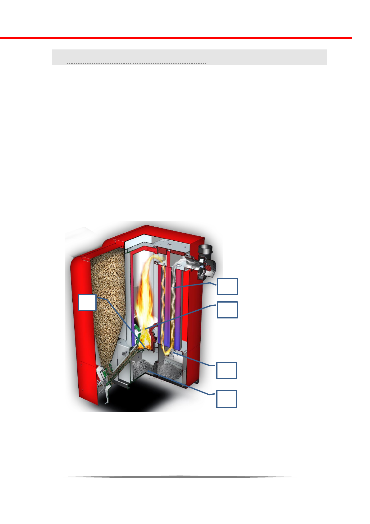
Boiler parts:
1. Burning
chamber
2. Automatic grate
3. Ashtrays
4. Automatic
cleaning system
of the tube heat
exchanger
5. Tube heat
exchanger
3. GENERAL OVERVIEW
EcoLogic boiler is a high-class boiler, in the range of the best boilers at the European
market.
The boiler control supports the connection of up to three circulation pumps, mixing valve
motor, hot water storage tank and sanitary water boiler.
An optional modem for Internet connection can be ordered as an accessory. The user can
have full control of the boiler via the application (to enable/disable, change power,
temperature or program it).
Cross section of the boiler
1 5 4
2
3
16
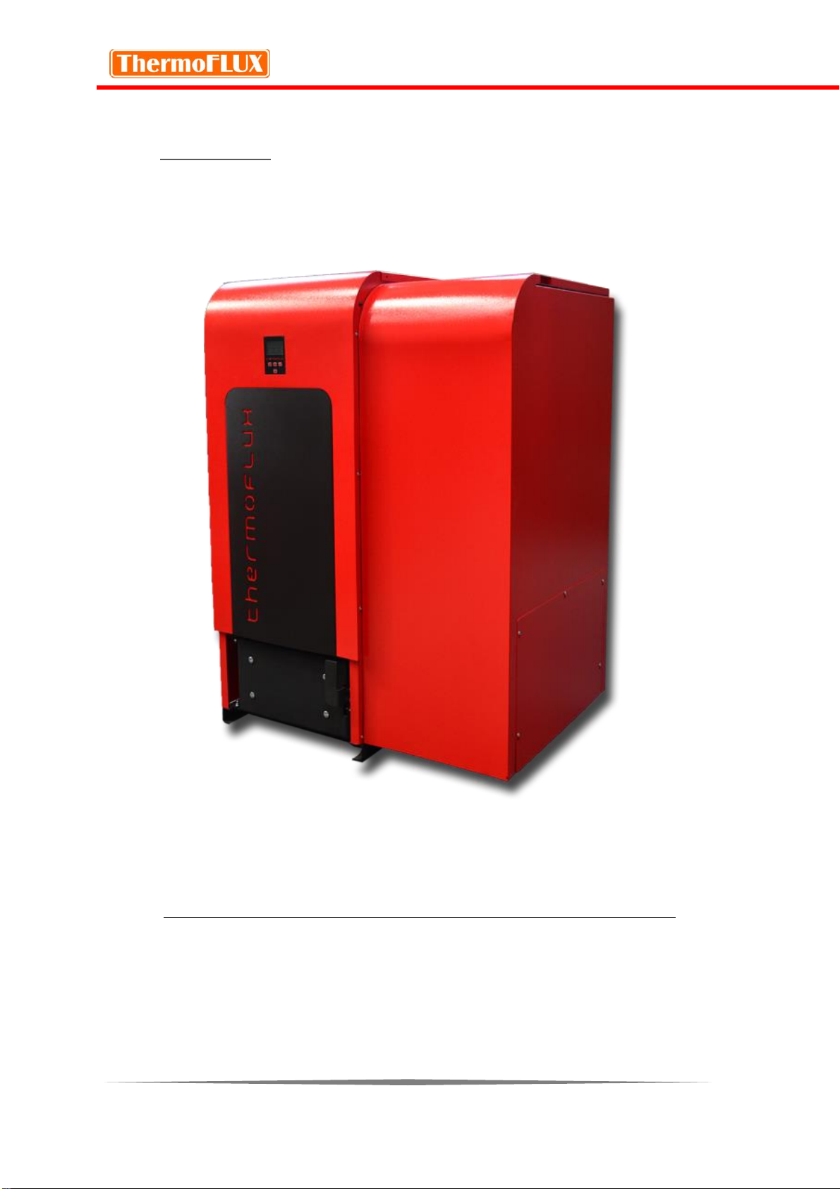
EcoLogic
Identification and serial number
The technical data label and the serial number are located on the back of the boiler.
17
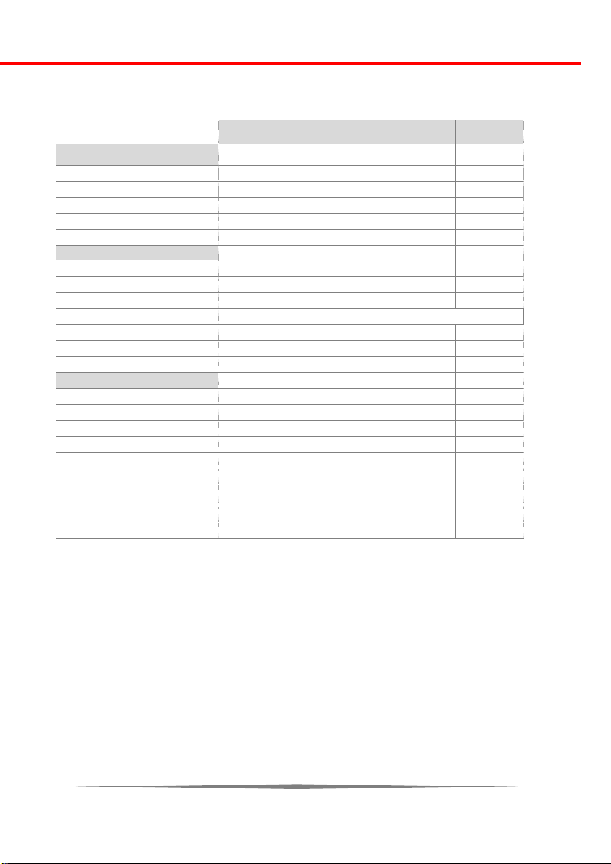
Technica l data
EcoLogic
25
EcoLogic
35
EcoLogic
44
EcoLogic
55
Performance (measured
according to EN 303-5: 2012)
Maximum power
kW
25
35
44
55
Minimum power
kW 8 11
13
17
Electrical conection
V,Hz
230 V, 50 Hz
230 V, 50 Hz
230 V, 50 Hz
230 V, 50 Hz
Electrical conection (current)
A
10
10
10
10
Boiler class
5 5 5
5
General information
Max. Permited presure
bar
2,5
2,5
2,5
2,5
Max. Permited temperature
°C
85
85
85
85
Min. permited return temperature
°C
55
55
55
55
Fuel
EN PLUS - UNI EN 14961 - 2 (UNI EN ISO 17225-2) Class A1 / A2
Pellet consumption min / max
kg
1,7 / 5,4
2,4 / 7,5
3 / 9,5
3,9 / 11,9
Pellet silo capacity
kg
170
170
170
200
Fresh air opening
cm
30x15
30x15
30x15
30x15
Technical data
Boiler width with pellet silo
mm
1050
1050
1050
1050
Height
mm
1270
1460
1460
1650
Depth
mm
1100
1100
1100
1100
Water content
l
55
68
90
115
Weight
kg
370
395
415
455
Height out / return
mm
1125 / 603
1315 / 603
1315 / 685
1505 / 685
Chimney underpresure
Pa /
mbar
5 / 0,05
5 / 0,05
5 / 0,05
5 / 0,05
Flue gas pipe height (direction UP)
mm
1250
1440
1440
1630
Flue gas pipe diameter
Ø
130
130
130
130
* minimal power - 30 % maximum
power
18
4. INSTALLATION
The commissioning of the system must be carried out by the personnel
authorized by ThermoFLUX d.o.o or the importer.
The warranty will not be valid if the boiler has not been commissioned
by an authorized servicer.
The first start-up includes the basic operation and maintenance of the boiler. The service
technician authorized for the first commissioning must check the functioning of the boile at
least during one complete work cycle. In some countries, it is obligatoy for first
commissioning to be controled and autorizied by chimney sweep or a person authorized
to control.
Risk of material and physical damage due to improper
commissioning. If the first start-up is done by an
unprofessional person, damage to the boiler and the
heating system may occur.
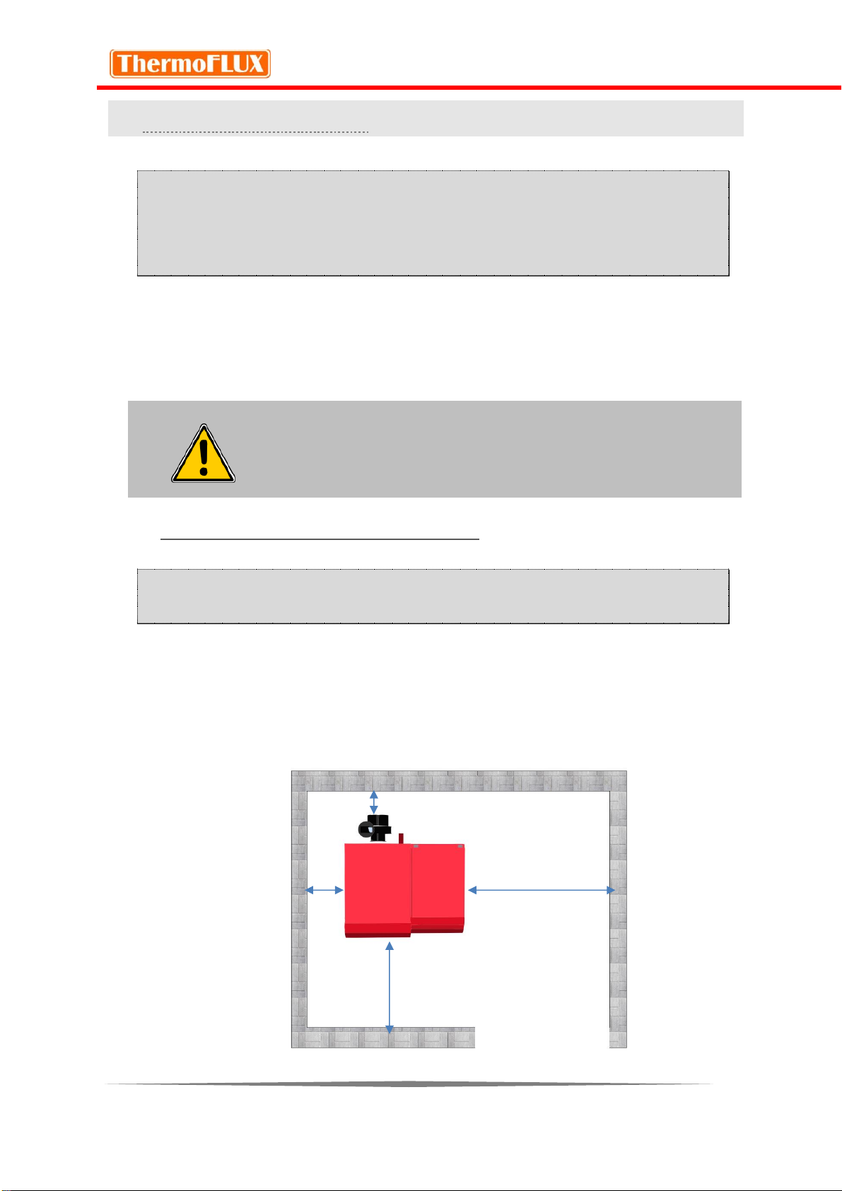
Conditions for installation
The following conditions must be completed before the system is
released.
The installation of the boiler must be done according to the regulations - with
a minimum distance of 50 cm from the side, ie 40 cm from the back of the
boiler measured from the flue gas fan. Distance in front of the boiler must be
at least 100 cm.
Min. 40 cm
Min. 50 cm
Min. 50 cm
Min. 100 cm
19
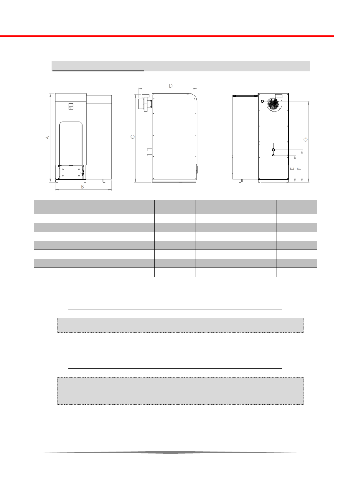
Boiler dimensions
EcoLogic
25
EcoLogic
35
EcoLogic
44
EcoLogic
55
A
Height
1270
1460
1460
1650
B
Width
1050
1050
1050
1050
C
Height of the flue outlet
1250
1440
1440
1630
D
Depth
1100
1100
1100
1100
E
Drain outlet
505
505
505
505
F
Return connection height
603
603
603
603
G
Output connection heght
1125
1315
1315
1505
Switch off main power supply
Be sure to turn off the main power before any work!
Check mechanical connections
• Check that all components are properly connected.
• Check that all mechanical components are securely attached.

20
Check hydraulic conections
Check that the circulation pump and the mixing valve are
properly connected.
Check that the safety equipment is properly connected
After completing the work, fill the system and wait an hour to
control all connections.
The boiler can be connected to an open or closed heating system.
With the connection to the open heating system, the open expansion vessel must be at a
height of 50 cm above the highest heating body and well insulated.
With the connection to the closed heating system, the safety valve and the membrane
expansion vessel must be installed as close as possible to the boiler and there can't be any
valves between them.

21
Hydraulic diagrams and connection mode s for individual system configu ration s
The boiler control supports the connection of three (3) circulation
pumps, mixing valve motor, buffer tank and sanitary water tank.
Only qualified service technicians have access to technical parameters
and settings, and can adjust the hydraulic connection.
The operation system will be adjusted according to the conducted
installation.
Electronic regulation supports connection to three heating circuit pumps, ie outputs: P1, P2
and P3.
P1 pump output can be used for the heating circuit 1 or by activating
the buffer for that circuit
P2 pump output can be used for the heating circuit 2 or by activating
the sanitary boiler for that circuit
The pump output P3 can be used for the remaining heating circuit 3.
Motor mixing valve output can be used only for one heating circuit
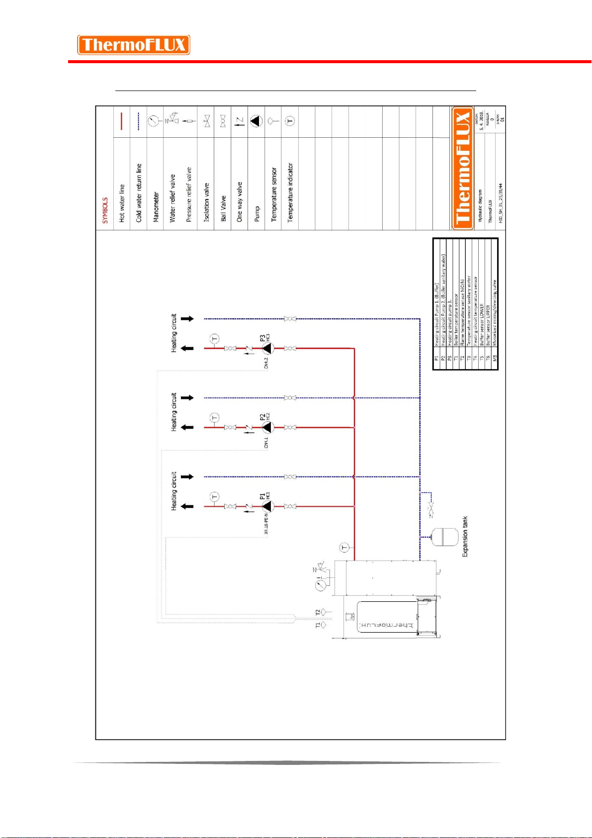
22
Hydraulic conection diagrams
 Loading...