

Page 1
VeritiPro™ Thermal Cycler Installation and Operation
1
1
Catalog Number A47394
Doc. Part No. 100093319 Pub. No. MAN0019367 Rev. A.0
Note: For safety and biohazard guidelines, see the “Safety”
appendix in the VeritiPro™ Thermal Cycler User Guide
(Pub. No. MAN0019157). Read the Safety Data Sheets (SDSs) and
follow the handling instructions. Wear appropriate protective
eyewear, clothing, and gloves.
Product description
This document summarizes procedures for installing and using the
VeritiPro™ Thermal Cycler with 6-zone 96-well 0.2 mL block and
VeriFlex™ "better than gradient™" technology. For detailed
instructions, see the VeritiPro™ Thermal Cycler User Guide (Pub. No.
MAN0019157).
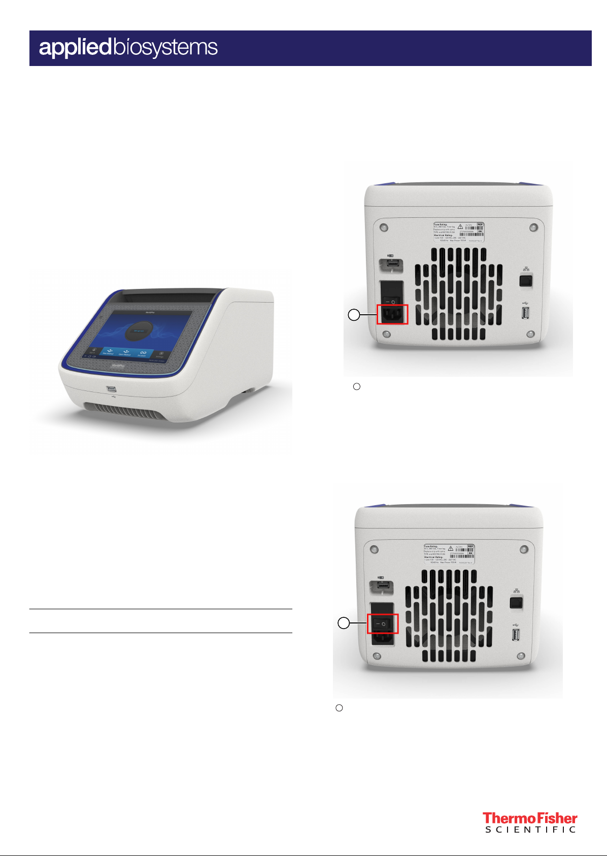
5. Connect the instrument to a power outlet.
a. Connect the power cord to the instrument.
QUICK REFERENCE
Fig. 1 VeritiPro™ Thermal Cycler
Required materials not provided
• Can of compressed air (For use in cleaning wells of sample
block).
• (Optional) Electrical protective devices.
Note: The use of one or more of the following electrical
protective devices is recommended.
Power line regulator (100–240 V)
·
Surge protector/line conditioner (10-kVA)
·
Uninterruptible power supply (1.5-kVA)
·
Set up the VeritiPro™ Thermal Cycler
IMPORTANT! Save the packing materials and box in case you
need to ship the instrument in for service.
1. Open the shipping crate to unpack the instrument. You should
receive one box containing the thermal cycler and the
accessories.
2. Remove the packing material, then inspect the instrument for
shipping damage.
3. Use compressed air to clear out each well of the sample block
to remove particles that may have collected inside during
shipping.
4. Move the instrument to an installation site that meets the
spatial and weight requirements for the thermal cycler (see
“Technical specifications” on page 5).
1
Power cord port
b. Install any desired electrical protective devices.
c. Connect the power cord to a wall plug.
6. Turn the power switch on, then wait for the instrument to start
up. Proceed with the installation after the touchscreen displays
the Home screen, indicating that the instrument is active.
When you power on the instrument, the instrument will take
under a minute to start up.
1
Power switch
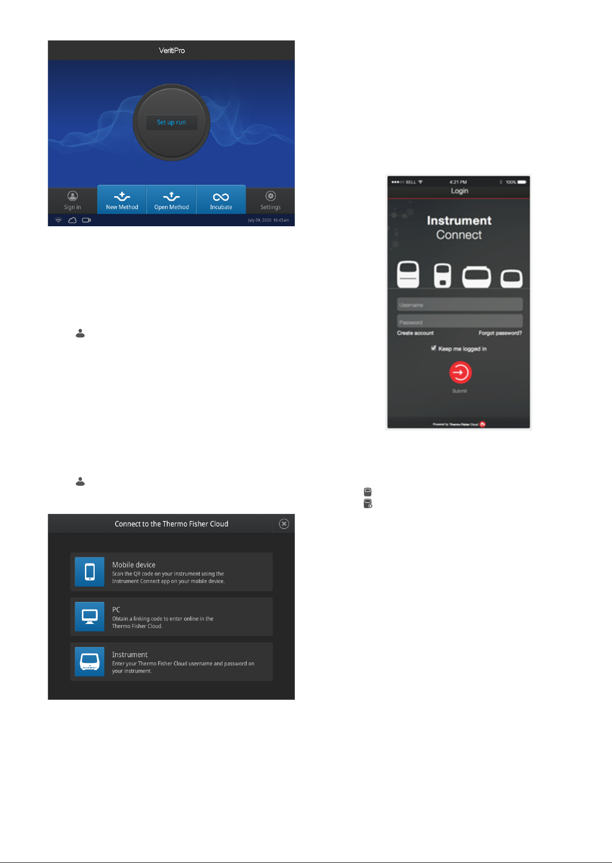
The Home screen will display following successful installation.
For Research Use Only. Not for use in diagnostic procedures.
Page 2
Connect the PCR instrument to the Internet
Connect your thermal cycler to the Internet. See the instrument user
guide for detailed instructions.
• Connect through the instrument Ethernet port using a cable.
• Connect via wireless connection with the High-Power USB Wi-Fi
Module (Cat. No. A26774).
Create a user profile on the PCR instrument
1. Select (Sign In) > Get started > Create profile.
2. Fill in the required text fields and enter a four digit PIN to create
your user profile.
Note: The first profile created is automatically given an
Administrator profile (indicated by an asterisk after the
Username).
Connect by mobile device
1. Download the "Instrument Connect Mobile Application" on
your mobile device.
a. For iPad™ or iPhone™ devices, download the application
from the iTunes™ music store by searching for Instrument
Connect by Thermo Fisher Scientific.
b. For Android devices, download the application from
Google™ Play by searching for Instrument Connect by
Thermo Fisher Scientific.
2. Launch the Instrument Connect Mobile Application and log in
using your Connect login and password.
Create a Connect account
1. Go to thermofisher.com/connect from your web browser.
2. Click Sign up now and follow the prompts to create an
account.
Link the PCR instrument to Connect
1. Select
the instrument.
2. Select the method for linking the instrument to Connect .
(Sign In) > Connect, then select the cloud region of
3. Capture the QR code on the instrument screen.
Connect by PC
1. Log in to your Connect account using a web browser from a
computer.
2. Select (InstrumentConnect) from the left navigation strip.
3. Select
4. Select VeritiPro from the drop down menu, then click Next.
5. Enter the linking code generated by the instrument in the text
box, then click Send.
Upon successful authentication, the instrument is linked to
Connect.
(Add an Instrument) from the top navigation strip.
Connect by instrument
1. Enter your Connect Username and Password from the
instrument.
2. Click Link account.
Note: If you do not have a PIN, you will be prompted to create
one.
Upon successful authentication, the instrument is linked to
Connect.
2
VeritiPro™ Thermal Cycler Quick Reference
Page 3

How to use the VeritiPro™ Thermal Cycler
1
2
3
1
1
2
4
3
5
Operate the instrument using the touchscreen. For detailed
instructions on using the thermal cycler, see the VeritiPro™ Thermal
Cycler User Guide (Pub. No. MAN0019157).
In the Home screen for the Touchscreen, you can set up a run by
creating a new method for a run. To set up a run using a new
method:
1. Press New Method or where it says Set Up Run.
2. Select a template.
3. In the edit mode, edit the parameters of the method template
such as temperature, time, number of steps/stages.
4. To access advanced editing options, press Manage Steps >
Advanced Options. Advanced editing options include VeriFlex
blocks for optimization, simulation modes, ramp rates, and
AutoDelta.
5. Save the new method in a folder.
6. (Optional) Press Start Run to start the Method.
™
Prepare samples using MicroAmp
tubes/tube strips with
separate cap strips
The following procedure describes how to properly load and seal
MicroAmp tube strips using cap strips and the MicroAmp 96-well
tray/retainer set. For a visual demonstration, watch the video "How
to use adapter tray retainers" by visiting PCR/qPCR Plastics and
Seals Education.
1. Separate the blue tray and retainer by squeezing the release
catch as indicated in the graphic.
™
Maintenance guidelines
CAUTION! During instrument operation, the temperature of
the heated cover can be as high as 110°C, and the
temperature of the sample block(s) can be as high as 100°C.
Before performing the procedure, keep hands away until the
heated cover and sample block(s) reach room temperature.
To ensure proper operation:
• Regularly:
– Wipe the instrument surfaces with a lint-free cloth.
– Clean the vents, touchscreen, and sample block of the
instrument.
– Clean the sample wells with 100% isopropanol.
• Use only consumables recommended by Thermo Fisher
Scientific for the instrument.
Use of consumables that are larger or smaller than the specified
volume can damage the instrument, contaminate the sample
block, and/or decrease the PCR yield (due to inecient thermal
transfer).
• Do not use sharp objects on the touchscreen.
Use only your fingers or blunt objects to enter commands on the
instrument touchscreen. Sharp and/or pointed objects such as
writing utensils can damage the surface of the touchscreen.
• Back up frequently.
Routinely back up the configurations and files on your
instrument to a USB drive. Regular backups protect against
data loss caused by user error, power failure, or instrument
error. For more information, see the VeritiPro™ Thermal Cycler
User Guide (Pub. No. MAN0019157).
1
Release catch
2
MicroAmp™ 96-Well Retainer
3
MicroAmp™ 96-Well Tray
2. Place the blue tray on the 96-well base.
3. Load the tube strips on the tray.
4. Pipette the reaction mixture into the tubes.
5. Place the blue retainer over the tubes and snap the retainer
into the tray.
6. Seal the tube strip using a MicroAmp™ cap strip. See “Seal
tube strips with cap strips” on page 4 for instructions.
7. Remove the blue tray/retainer assembly containing the sealed
tube strips from the 96-well base and place the assembly into
the instrument.
How to use the MicroAmp™ 96-well Tray and Retainer
IMPORTANT!
prevent crushing of tubes in the thermal cycler.
When small number of tubes (1–2 tube strips or ≤8–16 tubes are
placed in the sample block without support, they can be crushed or
deformed when the lid of the thermal cycler is closed over the
block. Using the tray and retainer set allows the pressure to be
distributed evenly over the tubes and prevents uneven pressure
across the block.
Using the tray and retainer set is optional when using ≥3 tube strips
or ≥16 tubes that are distributed evenly across the block.
• The blue tray and retainer set is compatible for use with
MicroAmp™ single tubes or tube strips with separate cap
strips.
• The blue tray by itself is compatible for use with MicroAmp
tube strips with attached caps.
• The black retainer is compatible for use with single MicroAmp
reaction tubes with attached caps.
VeritiPro™ Thermal Cycler Quick Reference 3
Use the MicroAmp™ 96-well Tray and Retainer to
1
MicroAmp™ 8-Cap strip
2
MicroAmp™ 96-Well Retainer
3
MicroAmp™ 8-Tube Strip (0.2-mL) or MicroAmp™ Reaction Tube
without Cap (0.2-mL)
4
MicroAmp™ 96-Well Tray
5
MicroAmp
™
™
™
Splash Free 96-Well Base
Page 4

Prepare samples using MicroAmp™ tube strips with
1
2
3
1
1
2
3
attached caps
The following procedure describes how to properly load and seal
MicroAmp tube strips with attached caps using the MicroAmp 96well tray/retainer set. For a visual demonstration, watch the video
"How to use adapter tray retainers" by visiting PCR/qPCR Plastics
and Seals Education.
1. Separate the blue tray from the retainer by squeezing the
release catch as indicated in the graphic.
1
Release catch
2
MicroAmp™ 96-Well Retainer
3
MicroAmp™ 96-Well Tray
2. Place the blue tray on the splash-free 96-well base.
Note: Only the bottom tray is used for tubes with attached
caps.
3. Load the tube strips with attached caps into the tray.
4. Pipette the reaction mixture into the tubes.
5. Seal the cap strips using the rocking capping tool:
Seal tube strips with cap strips
IMPORTANT! Apply significant downward pressure on the sealing
tool in all steps to form a complete seal on top of the tubes.
1. Align and place the cap strips on the tubes.
2. Seal the cap strips using the rocking capping tool:
a. Slip your fingers through the handle with the holes in the tool
facing down for domed caps and with holes facing up for
optical caps.
b. Align the tool over the first eight caps in a row.
c. Rock the tool back and forth a few times to seal the caps.
d. Repeat for all remaining rows.
Prepare samples using MicroAmp™ Reaction Tubes
The following procedure describes how to properly load and seal
MicroAmp™ individual tubes with attached caps and the MicroAmp
96-well tray for VeriFlex systems. For a visual demonstration, watch
the video "How to use adapter tray retainers" by visiting PCR/qPCR
Plastics and Seals Education.
1. Set the black tray on a 96-well base.
2. Place the reaction tubes in the black tray.
™
a. Slip your fingers through the handle with the holes in the tool
facing down for domed caps and with the holes facing up
for optical caps.
b. Align the tool over the first eight caps in a row.
c. Rock the tool back and forth a few times to seal the caps.
d. Repeat for all remaining rows.
6. Remove the blue tray containing the sealed tube strips from
the 96-well base and place the tray and sealed tube strips into
the instrument.
1
MicroAmp™ 8-Tube Strip with Attached Caps (0.2-mL)
2
MicroAmp™ 96-Well Tray
3
MicroAmp™ Splash Free 96-Well Base
1
MicroAmp™ Reaction Tube with Cap (0.2-mL)
2
MicroAmp™ 96-Well Tray for VeriFlex™ Blocks
3
MicroAmp™ Splash Free 96-Well Base
3. Pipette the reaction mixture into the reaction tubes.
4. Cap the tubes.
5. Remove the black tray with sealed reaction tubes from the 96-
well base and place the tray and sealed tubes into the
instrument.
4
VeritiPro™ Thermal Cycler Quick Reference
Page 5

Technical specifications
Feature Specification
Maximum block ramp rate
Maximum sample ramp rate 4.4°C/sec
Temperature accuracy ±0.25°C (35–99.9°C)
Temperature range for protocol run 0.0–100.0°C
Temperature non-uniformity
Dimensions
Weight 12 kg (16.5 lb)
PCR volume range
Instrument memory USB, 16 GB on-board
Display interface 8 inch color TFT LCD
Power 100–120 VAC, 200–240 VAC,
VeriFlex™ block
Ambient humidity 15–80% Relative Humidity, non-
Ambient operating temperature 15–30°C (acceptable range)
[1]
[2]
6.0°C/sec
≤0.5°C
• Height: 21.7 cm (8.54 in)
• Width: 24.5 cm (9.65 in)
• Depth: 46.5 cm (18.31 in)
• Supported: 10–100 µL
• Allowable: 1–100 µL
50–60 Hz, Maximum 700 W
• 6 VeriFlex™ Zones
• Supported: 25°C (5°C zone-tozone)
• Allowable
[3]
: 30°C (10°C zone-
to-zone)
condensing (acceptable range)
[1]
Reaction volume of 1 µL.
[2]
30 seconds after clock starts.
[3]
Temperature accuracy ±0.5°C and Temperature non-uniformity < 0.75°C.
Power and communication port symbols
Port Description
AC power cable port
10/100 Fast Ethernet port for connecting to a network
USB v2.0 port for connecting to an external network
drive, jump drive, or other USB storage device
USB v2.0 port for connecting to USB-enabled Wi-Fi Card
Life Technologies Holdings Pte Ltd | Block 33 | Marsiling Industrial Estate Road 3 | #07-06, Singapore 739256
For descriptions of symbols on product labels or product documents, go to thermofisher.com/symbols-definition.
The information in this guide is subject to change without notice.
DISCLAIMER: TO THE EXTENT ALLOWED BY LAW, THERMO FISHER SCIENTIFIC INC. AND/OR ITS AFFILIATE(S) WILL NOT BE LIABLE FOR SPECIAL, INCIDENTAL, INDIRECT,
PUNITIVE, MULTIPLE, OR CONSEQUENTIAL DAMAGES IN CONNECTION WITH OR ARISING FROM THIS DOCUMENT, INCLUDING YOUR USE OF IT.
Important Licensing Information: These products may be covered by one or more Limited Use Label Licenses. By use of these products, you accept the terms and conditions of
all applicable Limited Use Label Licenses.
©2020 Thermo Fisher Scientific Inc. All rights reserved. All trademarks are the property of Thermo Fisher Scientific and its subsidiaries unless otherwise specified.
thermofisher.com/support | thermofisher.com/askaquestion
thermofisher.com
15 June 2020
 Loading...