

Page 1

HyPerforma Single-Use Fermentor
(S.U.F.) User’s Guide
DOC0031 • Revision G
February 2021
Page 2

Contents
Warnings, safety, and warranty information 1
How to use this guide 7
Chapter 1 Single-Use Fermentor (S.U.F.) overview 10
1.1 Introduction 11
1.2 Hardware characteristics 14
1.2.1 System features 14
1.2.2 Agitation 14
1.2.3 Control system 14
1.2.4 Exhaust management system 14
1.2.5 Exhaust vent filter heater 14
1.2.6 Temperature 15
1.2.7 Heating performance 15
1.2.8 External control 15
1.2.9 Load cells 15
1.3 End user and third-party supplied components 16
1.3.1 pH and dissolved oxygen (DO) probes 16
1.3.2 Single-use probes 16
1.3.3 Controllers 17
1.4 BioProcess Container characteristics 18
1.4.1 Single-Use Fermentor BPC features 18
1.4.2 Operating pressure 18
1.4.3 Working volume 18
1.4.4 Draining and harvest 19
1.4.5 Aeration 19
1.4.6 Aseptic connections 19
1.4.7 Sampling 19
1.4.8 BPC features 20
1.5 Additional system components 22
1.5.1 Probe integration 22
1.5.2 Accessories 22
Page 3

Contents
Chapter 2 Installation and setup 24
2.1 Initial installation preparation 25
2.1.1 Hardware shipment and setup 25
2.2 Site preparation 25
2.2.1 Electrical connections for units with an electrical
control box 25
2.2.2 Outer support container preparation 26
2.2.3 Electrical preparation for systems with electrical
control boxes 26
2.2.4 Load cell preparation 27
2.3 Installation 28
2.3.1 Exhaust filter bracket setup 30
2.3.2 Condenser unit setup (when present) 31
2.3.3 TCU/chiller connection to condenser unit
(when present) 32
2.3.4 Exhaust filter pinch clamp setup (when present) 33
2.3.5 Optional cable management system setup 35
2.3.6 Air line preparation 35
2.3.7 Drilled hole sparger line(s) 35
Chapter 3 Operating information 36
3.1 General system operating information 37
3.1.1 BPC preparation and loading 37
3.1.2 BPC handling instructions 37
3.1.3 BPC operating information 37
3.1.4 Hardware operating information 39
3.2 BPC and drive shaft loading for 30 L units 43
3.2.1 Initial installation steps for 30 L units 43
3.2.2 Drive shaft insertion for 30 L units 51
3.2.3 Final installation steps for 30 L units 54
3.3 BPC and drive shaft loading for 300 L units 56
3.3.1 Initial installation steps for 300 L units 56
3.3.2 Drive shaft insertion for 300 L units 64
3.3.3 Final installation steps for 300 L units 69
3.4 Exhaust system 72
3.4.1 Exhaust system functional overview 72
3.4.2 When to use the condenser 73
3.4.3 Condensers and reserve vent filters 74
Page 4

Contents
3.4.4 Exhaust system setup 74
3.4.5 Exhaust system setup 75
3.5 Probe assembly 79
3.5.1 Preparation and sterilization 79
3.5.2 Making CPC AseptiQuik connections 80
3.5.3 Probe insertion 83
3.5.4 Probe calibration 85
3.5.5 Kleenpak connection instructions 85
3.6 Microbial cell culture operating instructions 95
3.6.1 Operating conditions for cell culture applications 95
3.6.2 Manual operation of drilled hole spargers 96
3.6.3 Checkpoints prior to media fill 97
3.6.4 Media fill 97
3.6.5 Agitation for units with electrical control boxes 98
3.6.6 Temperature control 99
3.6.7 pH probe calibration 100
3.6.8 DO probe calibration 100
3.6.9 Checkpoints prior to inoculation 100
3.6.10 Cell inoculation 100
3.6.11 In-process checkpoints 101
3.6.12 Dispense and harvest 101
3.6.13 S.U.F. shutdown and post-use BPC disposal 102
3.6.14 Preparation for the next run 103
3.7 BPC sampling 104
3.7.1 Aseptic sampling 104
3.7.2 Sampling with sterile manifold 105
3.8 Verification procedures 107
3.8.1 Mixer speed verification 107
3.8.2 Temperature controller verification 107
3.8.3 Pressure monitor verification (when present) 107
3.8.4 Load cell verification (when present) 107
Chapter 4 Specifications and parts information 108
4.1 Hardware features and dimensions 109
4.1.1 30 L S.U.F. design features 109
4.1.2 300 L S.U.F. design features 110
4.1.3 30 L S.U.F. dimensions and ordering information 111
4.1.4 300 L S.U.F. dimensions and ordering information 112
Page 5

Contents
4.2 30 L and 300 L S.U.F. hardware specifications 113
4.3 Configurable hardware options 115
4.4 BPC features and specifications 116
4.4.1 Standard 30 L S.U.F. BPC 116
4.4.2 Standard 300 L S.U.F. BPC 118
4.5 BPC options and packaging information 120
4.6 Accessories and options specifications 121
4.6.1 Load cells 121
4.6.2 Cable management system 124
4.6.3 Vent filter heaters 125
4.6.4 Exhaust system 126
4.6.5 Miscellaneous items 129
Chapter 5 Maintenance and troubleshooting 132
5.1 Maintenance 133
5.1.1 Routine maintenance 133
5.1.2 Preventive maintenance schedule 133
5.2 Troubleshooting and frequently asked questions 135
5.2.1 Hardware operation issues 135
5.2.2 Cell culture operation issues 137
5.2.3 Probe and connector issues 140
5.2.4 BPC and sparging issues 141
Chapter 6 General ordering information 142
6.1 Ordering instructions 143
6.2 Ordering/support contact information 143
6.3 Technical support 144
Appendices Appendix A—Installation of female electrical receptacle
for units with AC motors and electrical boxes 145
Appendix B—Mettler Toledo IND331 Display load cell
calibration instructions 148
Appendix C—Pre-fermentation run checklist 150
Page 6

Warnings, safety, and warranty information
Warnings, safety, and warranty
information
Thank you for purchasing the Thermo Scientific™ HyPerforma™
Single-Use Fermentor (S.U.F.). We have included safety information in
this guide, based on our knowledge and experience. It is important,
however, for you to work with your Safety Management personnel to
ensure that this equipment is integrated into your safety practices.
Please take some time to perform your own job safety analysis in order
to identify and control each potential hazard.
WARNING: Read and understand this user’s guide before
operating this equipment.
The Thermo Scientific HyPerforma Single-Use Fermentor (S.U.F.)
is designed to be operated under traditional microbial cell culture
conditions. A general understanding of Fermentor systems and their
operation is important prior to using the system for the first time. Read
and understand user’s guide before operating; failure to do so could
result in injury. Proper procedures for the disposal of Single-Use
BioProcess Containers (BPCs) should be followed, depending on
the culture in use. See the appropriate section of this guide.
WARNING: Tipping hazard. The vessel should only be moved by
pushing using the provided handles or at the mid-point of the
vessel.
If pulled or moved too quickly, the vessel can tip, potentially leading
to damage to equipment or injury to personnel. To reduce the risk
of tipping, the vessel should only be moved slowly over smooth, flat
surfaces by at least two qualified personnel. During movement, any
locking feet should be retracted, and casters should be in the unlocked
position. The vessel should not be moved by pulling of any kind.
WARNING: Hazardous voltage inside.
Electrical components are required for the proper function of the
S.U.F. The mixer motor, motor controller, and control panel all have
electrical components. There is a risk of electrical shock and injury.
Disconnect power before opening electrical components. Service
by trained personnel only. Thermo Fisher Scientific recommends
using standard lockout procedures when working on electrical
components. The main breaker on the electrical control panel may
be locked out.
HyPerforma Single-Use Fermentor User’s Guide | 1Thermo Scientific
Page 7

Warnings, safety, and warranty information
WARNING: Static electricity may build up in BPCs.
• BPCs may act as insulators for electrostatic charge. If electrostatic
• Where applicable, a product contact stainless steel coupler may be
WARNING: Rotating parts—entanglement hazard.
Rotating and moving parts can cause injury. Keep hands away from
moving parts.
• Do not operate this equipment unless the supplied guarding is in
• It is the responsibility of the end user to assess this equipment
charge is transferred to a BPC, the charge may be stored in
the BPC and/or the product inside. This phenomena varies by
product and use; therefore, it is the sole responsibility of the end
user to ensure a hazard assessment is conducted and the risk of
electrostatic shock is eliminated.
grounded to the frame to dissipate electrostatic build up from the
material within a BPC. It is good practice to dissipate electrostatic
build up by grounding all BPCs prior to coming in contact with
them. When working with BPCs, the use of nonconductive
materials, such as nonconductive gloves, is recommended.
place and properly functioning.
and ensure that equipment and safeguards are in good working
condition, and that all operators are trained and aware of
entanglement hazards and associated protective devices, such as
hazard signs and guarding.
WARNING: Use ladders and elevated platforms with caution.
A few operations, such as mounting the motor to the 300 L S.U.F.
during setup, may require the use of a ladder or platform. Before use,
ensure the ladder has been inspected and weight-rated for its user.
When using a ladder or platform, be sure it is stable, maintain three
points of contact and make sure the steps are clean.
WARNING: Follow lockout/tagout procedures.
To prevent injury, when servicing equipment, use your company’s
lockout/tagout procedures to isolate electrical, mechanical, pneumatic,
hydraulic, chemical, thermal, gravitational or any other potential energy
and protect workers from the release of hazardous energy.
WARNING: Use caution with hazardous chemicals or materials.
Personnel servicing equipment need to know the hazards of any
chemicals or materials that may be present on or in the equipment.
Use general hazard communication techniques such as Safety Data
Sheets, labels and pictograms to communicate any hazards.
HyPerforma Single-Use Fermentor User’s Guide | 2Thermo Scientific
Page 8

Warnings, safety, and warranty information
WARNING: Hot surface—do not touch.
The heating jacket is designed to heat the inner vessel wall. Normal
operating conditions generate heat and could create hot surfaces.
• Hot surface inside
• Contact with surfaces may cause burns
• Do not touch while in operation
WARNING: The Thermo Scientific HyPerforma S.U.F. may not
be installed in a potentially explosive atmosphere as set forth
in the applicable EU ATEX Directive.
WARNING: Burst hazard.
The S.U.F. BPC chamber is under slight pressure under normal
operating conditions. Normal passive venting prevents any excess of
pressure building up within the chamber. Chamber pressure and inlet
line pressure should be monitored for proper settings.
• Do not exceed 0.03 bar (0.5 psi) pressure within the BPC
• Do not exceed 0.34 bar (5 psi) pressure in the section of BPC
• Make sure the vent filter is properly positioned and working
• Maintain a minimum gas flow of 0.1 vvm or 0.01 psi in the BPC
tubing between the inlet filter and the BPC
properly
while the impeller is spinning
Protective earth grounding
Protective earth grounding must be verified prior to plugging the
S.U.F. into any electrical outlet. Ensure the receptacle is properly earth
grounded.
Environmental conditions
• Operating: 17°C to 27°C; 20 to 80% relative humidity, noncondensing
• Storage: –25°C to 65°C
• Installation category II (over voltage) in accordance with IEC 664
• Altitude Limit: 2,000 meters
Water jacket vessel information
S.U.F. hardware unit with water jacket has been designed to be
operated with water as the heat transfer medium with temperatures not
exceeding 50°C (122°F) under 150 psig (1 MPa) operating pressure. For
the utmost safety it is recommended that the water jacketed S.U.F. be
operated at 75 psig or less.
HyPerforma Single-Use Fermentor User’s Guide | 3Thermo Scientific
Page 9

Warnings, safety, and warranty information
Note: The S.U.F. BPC operating limits for temperature are 5°C to 40°C.
The internal pressure should not exceed .003 bar (0.5 psi). The water
jacket is not required to be registered, inspected and stamped with the
Code U symbol per section U-1(c)2(f) of the ASME Boiler and Pressure
Vessel Code and/or European Pressure Equipment Directive (PED)
97/23/EC. Upon request, a Declaration of Conformity, PED Sound
Engineering Practices can be made available.
Electrical connections
Power should be supplied by a non-GFCI 15 amp circuit. Ground
faults occur when current is leaking somewhere, in effect, electricity is
escaping to the ground. Electrocution can occur when the human
body serves as the path for the leakage to the ground. A Ground
Fault Circuit Interrupter (GFCI) senses the current flowing to the ground
and switches off the power (trips the GFCI) in a fraction of a second at
currents well below those that are considered dangerous. Due to the
sensitivity of GFCIs to electrical leakage (a few mA), it is recommended
that the S.U.F. not be plugged into a GFCI outlet.
Warranty information
Any warranties, if applicable, covering this equipment exclude: (a)
normal wear and tear; (b) accident, disaster or event of force majeure;
(c) your misuse, fault or negligence; (d) use of the equipment in a
manner for which it was not designed; (e) causes external to the
equipment such as, but not limited to, external puncturing, power
failure or electrical power surges; (f) improper storage and handling of
the equipment; (g) use of the equipment in combination with equipment
or software that we did not supply; (h) equipment sold to you as ‘used’
products; (i) contact with improperly used or unapproved chemicals
or samples; (j) installation, removal, use, maintenance, storage, or
handling in an improper, inadequate, or unapproved manner, such as,
but not limited to, failure to follow the documentation or instructions in
the deliverables or related to the equipment, operation outside of stated
environmental or other operational specifications, or operation with
unapproved software, materials or other products; (k) manufacture in
accordance with requirements you gave us; (l) installation of software
or interfacing or use of the equipment in combination with software
or products we have not approved; (m) use of the deliverables
or any documentation to support regulatory approvals; (n) the
performance, efficacy or compatibility of specified components; and
(o) the performance of custom equipment or products or specified
components or achievement of any results from the equipment,
specified components or services within ranges desired by you
HyPerforma Single-Use Fermentor User’s Guide | 4Thermo Scientific
Page 10

Warnings, safety, and warranty information
even if those ranges are communicated to us and are described in
specifications, a quote, or a statement of work. ADDITIONALLY, ANY
INSTALLATION, MAINTENANCE, REPAIR, SERVICE, RELOCATION
OR ALTERATION TO OR OF, OR OTHER TAMPERING WITH, THE
EQUIPMENT PERFORMED BY ANY PERSON OR ENTITY OTHER
THAN US WITHOUT OUR PRIOR WRITTEN APPROVAL, OR ANY
USE OF REPLACEMENT PARTS WE HAVE NOT SUPPLIED, WILL
IMMEDIATELY VOID AND CANCEL ALL WARRANTIES WITH
RESPECT TO THE AFFECTED EQUIPMENT. IF THE EQUIPMENT
IS TO BE USED IN THE UNITED STATES, WE MAY VOID YOUR
WARRANTY IF YOU SHIP THE EQUIPMENT OUTSIDE OF THE
UNITED STATES.
Use restrictions
You must use this equipment in accordance with our documentation
and if applicable, with our other associated instructions, including
without limitation, a “research use only” product label or “limited use”
label license. This equipment is intended for research use or further
manufacturing in bioprocessing applications and not for diagnostic
use or direct administration into humans or animals, we do not submit
the equipment for regulatory review by any governmental body or
other organization, and we do not validate the equipment for clinical or
diagnostic use, for safety and effectiveness, or for any other specific
use or application.
HyPerforma Single-Use Fermentor User’s Guide | 5Thermo Scientific
Page 11

Warnings, safety, and warranty information
Seismic guidance
The buyer of the equipment is responsible for ensuring that countryspecific codes and seismic values are assessed for suitability of
equipment installation and safety at the designated site. In addition,
it is the buyer’s responsibility to assess the building structure for
the designated equipment to ensure correct seismic anchoring and
tethering designs for both the equipment and facility. It is highly
recommended that the buyer consult with a local, licensed third party
architecture and engineering firm to provide the buyer with correct
engineering analysis and stamped documentation prior to equipment
installation at the facility. In addition, the buyer will be responsible for
rigging and anchoring of the equipment to a specified, fixed location.
Upon request, Thermo Fisher Scientific can assist with establishing
compliant seismic anchoring and tethering designs for purchased
equipment based on building and country codes, at an agreed upon
fee.
It is also noted that movable equipment (i.e. non-fixed or caster mount)
is exempt from seismic design requirements according to ASCE
7-16, Chapter 13, section 1.4. Although these units are exempt from
the seismic design requirements of ASCE 7, it should be noted that
such equipment is susceptible to overturning during a seismic event.
Therefore, it is the responsibility of the buyer to address seismic safety
for movable equipment at the designated facility.
HyPerforma Single-Use Fermentor User’s Guide | 6Thermo Scientific
Page 12

How to use this guide
Rev. Date Section Change made Author
A.0 07/ 2 014 -- Initial release S. Jelus
A 11/ 2 0 16 -- Reformatted E. Hale
A 11/ 2 0 16 3.1.4, 4.2 Updated maximum temperature setpoint J. Brown/E. Hale
A 11/ 2 0 16 3.5.2 Added CPC AseptiQuik connection instructions E. Hale
A 11/ 2 0 16 3.5.5 Removed references to sterility E. Hale
A 11/ 2 0 16 4.2 Updated nominal tip speed E. Hale
A 11/ 2 0 16 Appendix D Added Appendix D (Pre-fermentation run checklist) J. Brown/E. Hale
B 04/2017 4.2
B 04/2017 4.2
B 04/2017 4.4.1
B 05/2017
B 05/2017 2.3, 4.1, 4.6
C 09/2017
C 09/2017 -- Changed values from “psi (bar)” to “bar (psi)” E. Hale
C 09/2017 -- Updated various aspects of formatting E. Hale
C 09/2017
C 09/2017 4.2 Added “Noise level” to specifications table E. Hale
C 11/ 2 0 17 Chapter 4 Removed hardware, BPC part numbers E. Hale
C 01/2018 -- Updated warning symbols E. Hale
How to use this guide
Scope of this publication
This user’s guide contains information about the standard Thermo
Scientific S.U.F. systems, including hardware, components, product
design verification methods, installation, operation, and specifications.
It is intended for use by people who may or may not have experience
with Thermo Scientific systems, but who have some knowledge of
bioproduction processes and large-scale mixing systems.
Document change information
Warnings and
Safety
Warnings, safety,
and warranty
information
How to use this
guide
Added Minimum Ceiling Height Requirement to 30 and 300
L specifications
Replaced “+/- 0.75% of full scale” with “+/- 5 rpm” in Motor
Speed specification field
Corrected part number for standard 30 L BPC with two 5 in.
exhaust filters
Added potentially explosive atmosphere (ATEX) warning E. Hale
Updated 30 L S.U.F. drawings to show the current motor
mount
Added warranty and usage information E. Hale
Added “Abbreviations/acronyms” section E. Hale
E. Hale
E. Hale
E. Hale
E. Hale
HyPerforma Single-Use Fermentor User’s Guide | 7Thermo Scientific
Page 13

How to use this guide
Rev. Date Section Change made Author
D 11/2 018
D 11/2 018
D 11/2 018 Various Removed references to metal probe clips E. Hale
D 11/2 018 2.2.3
D 11/2 018 3.6.5, 4.6.1 Updated Figures 3.104 and 4.12 E. Hale
D 11/2 018 Appendices Removed Appendix B (AC-Tech calibration) E. Hale
D 11/2 018
D 12 / 2018 3.1.3, 3.6.5 Edited sentence (3.1.3) and reworded step #2 (3.6.5) E. Hale
Warnings, safety,
and warranty
information
How to use this
guide
Warnings, safety,
and warranty
information
Added seismic guidance E. Hale
Changed “Input into Thermo Scientific publications” to
“Questions about this publication”
Updated Figure 2.1, showing the interior of S.U.F. E-Boxes,
and removed Figure 2.2
Added emphasis to “Electrical connections” section E. Hale
E. Hale
E. Hale
D 12 / 2018 4.2
E 10/ 2019 -- Minor revisions T. Golightly
E 10/ 2019 4.2 Updated cart length dimension on Table 4.2 T. Golightly
Warning, safety,
F 06/2020
G 11/2020 --
G 11/2020 4.1.3 Updated Figure 4.5 with new cart dimentions T. Golightly
G 11/2020 4.2
G 11/2020 1.3.1
and warranty
information
Added tolerance (± 5 rpm) to “Motor speed” in
specifications
Added Tipping hazard warning and symbol C. Jones
Minor updates to the document to meet current document
standards
Corrected the overall width, length, height and dry and wet
skid weights in Table 4.2
Updated the "Finesse pH and DO" sensors to "Hamilton pH
and DO" sensors in Table 1.1
E. Hale
T. Golightly
T. Golightly/E. Hale
T. Golightly
Questions about this publication
If you have any questions or concerns about the content of
this publication, please contact technicaldocumentation@
thermofisher.com and your Thermo Fisher Scientific sales team.
HyPerforma Single-Use Fermentor User’s Guide | 8Thermo Scientific
Page 14

How to use this guide
Related documents
If you are missing any of the related publications listed below, please
contact your local sales representative.
Document Document number
Thermo Scientific HyPerforma S.U.F. Validation Guide DOC0032
Thermo Scientific HyPerforma S.U.F. Packing and Unpacking
Instructions
DOC0052
Abbreviations/acronyms
Refer to the list below for definitions of the abbrieviations and acronyms
used in this publication.
BPC BioProcess Container
DO Dissolved oxygen
ETP Equipment Turnover Package
GFCI Ground fault circuit interrupter
ID Inner diameter
IEC International Electrical Code
OD Outer diameter
PED Pressure Equipment Directive
PID Proportional integral derivative
P/V Power input to volume
rpm Revolutions per minute
RTD Resistance temperature detector
slpm Standard liters per minute
STR Stirred tank reactor
S.U.F. Single-Use Fermentor
TCU Temperature control unit
VFD Variable frequency drive
HyPerforma Single-Use Fermentor User’s Guide | 9Thermo Scientific
Page 15

Chapter 1 | S.U.F. overview
1
Single-Use Fermentor
(S.U.F.) overview
Chapter contents
1.1 Introduction
1.2 Hardware characteristics
1.3 End user and third-party supplied components
1.4 BioProcess Container characteristics
1.5 Additional system components
HyPerforma Single-Use Fermentor User’s Guide | 10Thermo Scientific
Page 16

Chapter 1 | S.U.F. overview
1.1. Introduction
The Thermo Scientific Single-Use Fermentor (S.U.F.) has been designed
to be a single-use alternative to conventional stirred tank aerobic
fermentors currently utilized in microbial cell culture applications.
Based on years of accepted stirred tank reactor (STR) design, the
S.U.F. emulates STR scalability and operating parameters, yet it
has the unique advantage of being a single-use device. Ease of
setup with respect to system operation and integration into existing
facilities makes the S.U.F. an attractive alternative to its stainless steel
counterpart. Critical design parameters such as height to diameter
ratios, mixer design and location, and typical control system interfaces
are consistent with traditional fermentation platforms. S.U.F. BioProcess
Containers (BPCs) are supplied sterilized by irradiation and therefore
do not require any facility hook-ups for sterilization or cleaning. A key
element in the single-use design is the plastic (polyethylene) impeller
with a bearing/seal assembly linking to an external mixer drive. Quick
setup and changeover allows for faster turnover in microbial cell culture
runs over traditional reusable systems.
S.U.F. systems consist of the following primary components:
• Outer support container with standard water jacket heating
system
• S.U.F. BioProcess Container (BPC)
• Electrical control panel (E-Box) for agitation
• Direct drive agitation mixing assembly with an AC motor, drive
shaft, and impeller
HyPerforma Single-Use Fermentor User’s Guide | 11Thermo Scientific
Page 17

Chapter 1 | S.U.F. overview
Figure 1.1. 300 L S.U.F. with electrical
control panel, condenser, cable
management system, and bottle
management system.
The Thermo Scientific S.U.F. utilizes an open architecture design for
the control system, allowing for integration with customer systems
or with third-party controllers for feed pumps, mass flow controls,
and HMI (human-machine interface) screens. Controls for agitation
are integrated into the S.U.F., with temperature, pH/DO probes and
controls being supplied by the user or a third-party integrator. Water
jacketed systems require a temperature control unit (TCU) selected and
supplied by the end user or by Thermo Scientific.
The stainless steel outer support container is engineered and
fabricated to fully support each S.U.F. BPC and allow easy access
for operation. The outer support container is mounted to a portable
cart base and includes the mixing drive, water jacket for heating
and cooling, and optional controllers for mixing. The drive shaft is
detachable and reusable and is inserted into the BPC through the
motor assembly and into the bearing port. Load cells are offered as an
option.
HyPerforma Single-Use Fermentor User’s Guide | 12Thermo Scientific
Page 18

Chapter 1 | S.U.F. overview
The BPC includes the impeller assembly, sparger, vent filter inlet/outlet
ports, probe integration ports and filling, dispensing, and sampling
ports. The materials are fully qualified for biological product contact
per USP Class VI plastics. Each assembly is manufactured under
cGMP and is supported by qualification and validation information. No
reuse cleaning or sterilization validations are required as the BPC is
provided gamma irradiated. Innovative, proprietary technology allows
for the integration of the mixing shaft, pH and dissolved oxygen (DO)
probes, and the resistance temperature detector (RTD). The probe and
temperature interfaces are comparable to traditional systems with the
design allowing for simple, aseptic connections. Integrated spargers
are built into the S.U.F. BPC through universal ports.
This user’s guide covers the setup, operation, maintenance, and
troubleshooting of 30 and 300 L S.U.F. systems.
HyPerforma Single-Use Fermentor User’s Guide | 13Thermo Scientific
Page 19

Chapter 1 | S.U.F. overview
1.2. Hardware characteristics
1.2.1. System features
The S.U.F. is designed for system mobility and easy integration while
utilizing a straightforward operator interface. Hardware drawings and
specification tables specific to volume can be found in Chapter 4 of
this guide. The following topics include general descriptions of the
hardware components of the S.U.F.
1.2.2. Agitation
If your system uses a Thermo Scientific electrical control panel (E-Box),
the stirring speed is adjusted by using the keypad interface on the
control panel. The agitation control interface utilizes a digital display
to indicate stirring speed in units of revolution per minute (rpm). Power
is supplied to the motor by a two-position power switch. The up and
down arrows on the agitation keypad adjust the stirring speed. Your
system may also be integrated and managed by a third-party controller.
1.2.3. Control system
The S.U.F. is designed to integrate with existing control systems in
their many configurations. The S.U.F. control system supplied with the
Thermo Scientific E-Box enclosure manages the agitation process
and monitors the pressure inside the BPC. Parameters of pH and DO,
gas management, feed addition, and base addition control must be
managed by an external controller supplied by the end user or a thirdparty integrator.
1.2.4. Exhaust management system
A condenser system is recommended and is available as optional
hardware. It cools exhaust gases and re-circulates the condensate into
the fermentor.
1.2.5. Exhaust vent filter heater
An optional exhaust vent filter heater is available for increased longevity
of the exhaust filter on the S.U.F. BPC. Heating the filter sufficiently
to eliminate the formation of condensation is an effective means of
reducing the risk of fouling of the filter membrane. The heater is factory
preset to operate between 40–55°C, ± 3 degrees. Temperature
settings above 60°C are not recommended.
HyPerforma Single-Use Fermentor User’s Guide | 14Thermo Scientific
Page 20

Chapter 1 | S.U.F. overview
1.2.6. Temperature
The S.U.F. can be operated within the temperature range from 5–55°C.
The process temperature is measured by means of a supplied RTD
(pt-100) that is inserted into the thermowell of the S.U.F. BPC. Water
jacketed system temperature control is maintained through the TCU or
a third-party controller.
1. 2 .7. Heating performance
Heating times for S.U.F. systems vary based on operating liquid
volume and temperature, ambient or heating fluid temperature, sparge
rate, and mixing rate. Users should adjust process liquid staging
and seeding strategies to the unique aspects of the S.U.F. Process
controllers are designed to provide optimum heat transfer and to
minimize heat up times, while maintaining the material integrity of the
polymer film construction of the S.U.F. BPC. Refer to section 3.1.4 for
expected heating times.
1.2.8. External control
Users can choose to bypass the mixing speed control and display
pressure systems provided with the S.U.F. and utilize existing
controllers. Refer to section 3.6 for more details.
1.2.9. Load cells
Load cells, used to determine the weight of the contents of a S.U.F., are
optional. Load cell kits can be installed at the factory or can be added
later by a certified service technician. The load cell kit comes with three
load cells, summing block, wiring, and display with a choice of several
data interfaces.
Load cells arrive uncalibrated. It is recommended that the load cell
manufacturer or a qualified technician calibrate these systems on site.
HyPerforma Single-Use Fermentor User’s Guide | 15Thermo Scientific
Page 21

Chapter 1 | S.U.F. overview
Table 1.1. Manufacturers and models of compatible pH/DO probes.
Probe lengths (from O-ring to tip) must not exceed 235 mm (9.25 in.)
1.3. End user and third-party supplied
components
1.3.1. pH and DO probes
The following table shows the length and diameter requirements for
traditional sensors (probes) that can be integrated into the S.U.F. These
requirements are based on the necessary insertion depth of the probe
when used with the probe ports. Note: The presence of a properly
positioned O-ring on the probe is critical for use with the S.U.F.
O-ring to probe tip
Sensor Inserted
Probe Part number Diameter
AppliSens DO Z010023525 12 mm (0.47 in.) 13.5 PG
AppliSens pH Z001023551 12 mm (0.47 in.) 13.5 PG
Mettler Toledo DO
Mettler Toledo pH
Broadley-James DO D140-B220-PT-D9 12 mm (0.47 in.) 13.5 PG
Broadley-James pH F-635-B225-DH 12 mm (0.47 in.) 13.5 PG
Hamilton DO 237542 12 mm (0.47 in.) 13.5 PG
Hamilton pH 238633-2543 12 mm (0.47 in.) 13.5 PG
NOTE: Consult probe manufacturer’s website for appropriate probe cable connection and part number.
InPRO 6800/12/220,
PN 52200966
405-DPAS-SCK8S/225, PN
104054481IG
12 mm (0.47 in.) 13.5 PG
12 mm (0.47 in.) 13.5 PG
Thread
type
Length Length
235 mm
(9.25 in.)
235 mm
(9.25 in.)
215 mm
(8.46 in.)
195 mm
( 7.6 7 in. )
215 mm
(8.46 in.)
225 mm
(8.85 in.)
225 mm
(8.85 in.)
225 mm
(8.85 in.)
235 mm
(9.25 in.)
235 mm
(9.25 in.)
215 mm
(8.46 in.)
219 mm
(8.62 in.)
214 mm
(8.42 in.)
219 mm
(8.62 in.)
220 mm
(8.66 in.)
220 mm
(8.66 in.)
1.3.2. Single-use probes
Mettler Toledo single-use pH and DO sensors are supported, and
BPCs may be ordered with single-use sensors as fully integrated
components.
HyPerforma Single-Use Fermentor User’s Guide | 16Thermo Scientific
Page 22

Chapter 1 | S.U.F. overview
1.3.3. Controllers
Thermo Scientific operates with an open architecture approach to the
integration of controls. Our industry-leading S.U.F. can be integrated
with most controllers on the market, allowing customers to choose
the control system they want, or to reduce expense by integrating
with a controller that is already onsite. In order to facilitate integration,
electrical schematics are provided in the Equipment Turnover Package
(ETP) supplied with the Thermo Scientific S.U.F.
S.U.F. units may be provided with integrated controls, pump towers, a
control monitor, and advanced features, such as data logging, multiple
S.U.F. connections, and optional 21CFR part 11 compliance for cGMP
manufacturing. A variety of single-use sensors are available for pH,
DO, and pressure control. Thermo Scientific can provide complete,
integrated solutions with the Thermo Scientific OEM Controller, or using
the manufacturers listed below.
• Applikon SUB-Controller
• Legacy Finesse PC Controller
• Emerson Delta V
• Allen-Bradley
• Siemens
Contact your local sales representative for more information.
Note: The S.U.F. will work well with any of the various control system
platforms, such as PLC, PC, DCS, or proprietary operating system
based controllers.
HyPerforma Single-Use Fermentor User’s Guide | 17Thermo Scientific
Page 23

Chapter 1 | S.U.F. overview
1.4. BPC characteristics
1.4.1. S.U.F. BPC features
The microbial culture itself is contained inside the S.U.F. BPC
(Figures 1.2 and 1.3). The chamber is manufactured from single-web,
multi-layer film, which is a co-extruded structure specifically designed
for biopharmaceutical process usage. All materials are qualified for
a broad range of physical, mechanical, biological, and chemical
compatibility requirements (refer to data in our BPC Catalog, which is
available from your sales representative). The BPC is presterilized using
validated gamma irradiation processes.
1.4.2. Operating pressure
The S.U.F. BPC does not operate as a closed system, as it has both
inlet and exhaust filters that are utilized to maintain an environment for
cells to grow without concern for contamination. However, conditions
can be encountered when gas inlet flow rate may exceed exhaust
flow rate. This may be encountered in the unlikely event of a pressure
regulator failure on a gas feed, or when excessive foaming creates
conditions of vent blockage. The S.U.F. BPC is not rated as a pressure
vessel (gas pressure should not exceed 0.03 bar (0.5 psi) within the
BPC). Custom BPCs can be ordered with an optional single-use
pressure transducer for monitoring the pressure within the S.U.F.
1.4.3. Working volume
Each S.U.F. is designed for a working volume range. The minimum
working volume and the rated working volume are listed in the
specification tables provided in Chapter 4. The total volume listed
includes the head space needed for proper aeration and gas
management. Actual working volumes should not exceed the indicated
rated working volumes. In addition, working volumes less than the
minimums listed can result in damage to the BPC and S.U.F. hardware
malfunction.
HyPerforma Single-Use Fermentor User’s Guide | 18Thermo Scientific
Page 24

Chapter 1 | S.U.F. overview
1.4.4. Draining and harvest
The S.U.F. is equipped with a bottom drain line that allows for liquid
harvest, typically with a peristaltic pump. Connection of the bottom
drain line can be accomplished by use of a tubing welder or the aseptic
connection of quick connect or fitting that is provided. Manipulation of
the BPC as the last few liters of media are removed can minimize liquid
hold-up within the S.U.F.
1.4.5. Aeration
Gas to liquid mass transfer in microbial culture fermentors is controlled
by the solubility of the gas in the liquid, its distribution, and the
temperature and pressure. Direct air sparging is a way of providing
for the oxygen requirements of cell cultures. The standard S.U.F. BPC
incorporates a unique rind-like film sparger design that allows for
optimal aeration of the culture process.
1.4.6. Aseptic connections
Multiple aseptic connection options exist for S.U.F. users. The
standard BPCs include tubing welder sections, quick connects, CPC
™
AseptiQuik,
or Pall™ Kleenpak™ aseptic connections. The S.U.F.
BPC is designed with various lengths and dimensions of thermoplastic
tubing for the purpose of addition to and dispensing from the S.U.F.
BPC. Refer to ordering information in Chapter 4 for custom end
treatment options.
™
1.4.7. Sampling
The S.U.F. is equipped with a small volume sample port that is adjacent
to the BPC thermowell. This small diameter silicone dip tube of 152.4
mm length (6 in.) allows low void volume samples to be taken for
cell viability and density, as well as analyte analysis. This dip tube is
supplied with an aseptic luer lock connector (SmartSite
for direct sampling or attachment of various sampling manifolds by
use of standard luer lock connection. Alternatively, manifolds can be
™
welded onto the C-Flex
sample line by tubing welder.
™
) that allows
Detailed BPC drawings and standard configuration tables specific to
volume can be found in Chapter 4 of this guide.
HyPerforma Single-Use Fermentor User’s Guide | 19Thermo Scientific
Page 25
Chapter 1 | S.U.F. overview
1.4.8. BPC features
Figures 1.2 and 1.3 illustrate the components of standard 30 L and
300 L S.U.F. BPCs. See Table 1.2 on the following page for more
information.
1
4
6
11
Figure 1.2. 30 L S.U.F. BPC.
2
3
5
7
9
10
1
2
8
3
6
11
4
5
8
9
7
10
Figure 1.3. 300 L S.U.F. BPC.
HyPerforma Single-Use Fermentor User’s Guide | 20Thermo Scientific
Page 26

Chapter 1 | S.U.F. overview
Table 1.2. BPC information for Figures 1.2 and 1.3.
1. Exhaust vent filter Single-use capsule filter for exhaust gas exchange (two types available)
2. Condenser bag (optional) Optional single-use condenser bag
Component Description
3. Foam sensor (optional)
4. Seal/bearing assembly
Built-in single-use sensor may be used with a controller to automatically trigger
addition of an anti-foaming agent when excessive foam is present
Links with mixer motor and allows impeller to turn while retaining integrity of
the S.U.F. BPC
5. Feed ports Feed port for addition of media and other liquids
6. Impeller
Injection molded plastic; linked to seal/bearing assembly by C-Flex tubing
contact material of the shaft
7. Ports with single-use sensors
or standard Pall Kleenpak*
Ports with single-use sensors or standard Pall Kleenpak* connectors
connectors
8. Spare sterile connect port Spare port
9. Temperature RTD/ small volume
sampling port
10. Gas sparge line(s)
For integration of temperature probe while retaining integrity of the S.U.F. BPC,
and for needleless sampling or connection to sampling manifold
Drilled hole sparger integrated into the chamber and protected by gas filters
and a check valve (check valve is provided on 30 L units only)
11. Drain port Used when draining the S.U.F.
*CPC AseptiQuik aseptic connectors are also available on S.U.F. BPCs.
HyPerforma Single-Use Fermentor User’s Guide | 21Thermo Scientific
Page 27
Chapter 1 | S.U.F. overview
1.5. Additional system components
1.5.1. Probe integration
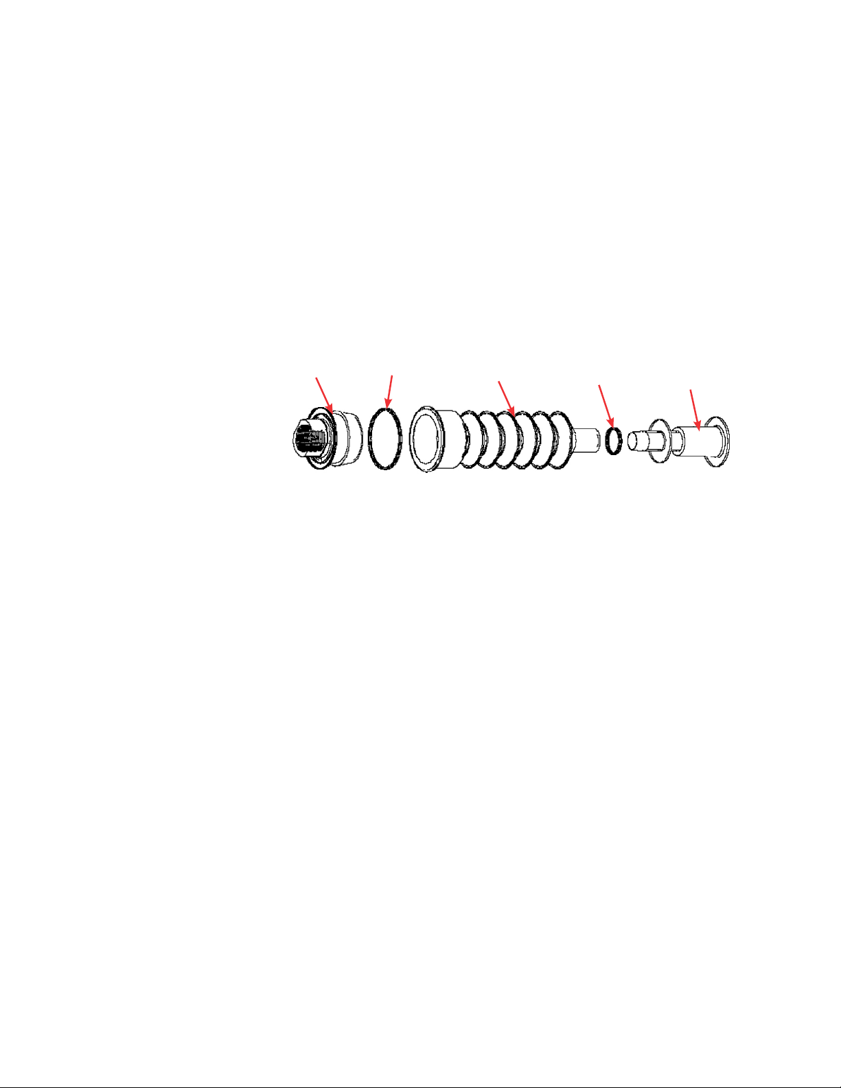
The probe assembly is an innovative design to package user-supplied
pH and DO probes for sterilization and to aseptically connect them to
the S.U.F. BPC. The probe assembly (Figure 1.4) includes the following
components:
1. Molded bellows cover
2. Threaded probe adapter
3. Pall Kleenpak connector (KPCHT series—high temperature)
4. Cable ties
2
Figure 1.4. Probe assembly.
Note: Figure 1.4 shows a Pall Kleenpak connector. CPC AseptiQuik
connectors are also available for S.U.F. systems.
4
1
4
3
1.5.2. Accessories
To assist in the operation of the S.U.F., additional accessories are
available (see accessories below).
Required
• Heavy-duty tubing clamps
Recommended
• Exhaust management system with condenser and vent filters.
Optional
• E-Box
• Sampling manifold with luer lock
• Temperature sample port (for RTD calibration/validation)
• Vent filter heater system—for users who require additional
protection for the exhaust vent filter on the standard S.U.F. BPC;
includes filter heater, controller, and power cord.
HyPerforma Single-Use Fermentor User’s Guide | 22Thermo Scientific
Page 28

Chapter 1 | S.U.F. overview
• Load cells—Load cell packages include three load cells, summing
block, wiring, and an optional display screen with your choice of
several data interfaces
• Cable management system
• Bottle management system
• Feed bag management hook
See Chapter 4 of this guide for accessory ordering information.
HyPerforma Single-Use Fermentor User’s Guide | 23Thermo Scientific
Page 29

Chapter 2 | Installation and setup
2
Installation and setup
Chapter contents
2.1 Initial installation preparation
2.2 Installation
HyPerforma Single-Use Fermentor User’s Guide | 24Thermo Scientific
Page 30

Chapter 2 | Installation and setup
2.1. Initial installation preparation
The Single-Use Fermentor (S.U.F.) hardware will arrive crated. For
unpacking instructions and detailed contents of the crate, please refer
to the S.U.F. Packing and Unpacking Guide (DOC0052).
There will be detailed instructions for crating, uncrating, and assembly
of 30 L and 300 L S.U.F. units. Be sure to follow the instructions
provided and retain all packaging materials. After uncrating, contact
your sales representative immediately if you find that any damage has
occurred in shipping.
2.1.1. Hardware shipment and setup
The S.U.F. hardware will arrive with the following items:
• Outer support container (platform, tank, and control panel)
• Drive shaft, resistance temperature detector (RTD), four probe
brackets, and standard tool set (spanner wrench and torque
wrench)
• Equipment Turnover Package (ETP) provided on a USB drive,
shipped separately
2.2. Site preparation
2.2.1. Electrical connections for units with an electrical
control panel
S.U.F. hardware with AC motors cannot be used on circuits equipped
with GFCI circuit protection due to the potential for nuisance tripping.
The electrical plug on the S.U.F. is a connector that offers a secure
ground. These connectors meet the electrical safety codes for portable
equipment and are International Electrical Code (IEC) rated (meet IEC
standard 60309). This plug serves to provide electrical ground prior
to power connection. The supplied electrical receptacle should be
hard-wired into the facility by a qualified electrical technician; for US
installations the receptacle will require the use of an adapter mounting
plate (supplied) which will fit into a two gang box. For additional
information on the adapter mounting plate, please see the ETP.
Alternatively, the system can be hard-wired directly into the facility.
Note: The yellow plug and receptacle are for 120 VAC and the blue are
for 240 VAC S.U.F.s.
HyPerforma Single-Use Fermentor User’s Guide | 25Thermo Scientific
Page 31

Chapter 2 | Installation and setup
2.2.2. Outer support container preparation
Each outer support container is shipped from the manufacturer and
arrives with various safety mechanisms in place. Please follow the
guidelines below to set up the S.U.F. upon arrival.
WARNING: Any procedures that require the electrical control panel
(E-Box) to be opened should be performed with the main electrical
disconnect in the locked out position, and all power sources removed.
For operator safety, secure the location of the S.U.F. unit by disabling
the swivel casters before servicing.
2.2.3. Electrical preparation for systems with electrical
control panels
1. Before beginning, refer to electrical schematics included with the
ETP, which is shipped on a USB drive.
2. Make sure the unit is disconnected from any power source, and
use standard lockout safety procedures.
3. Open the E-Box using a flat-head screwdriver. Verify that the
three-way motor controller switch is in the middle position
(Figure 2.1).
Motor controller
breaker
Main breaker
Motor controller
Figure 2.1. Internal view of typical S.U.F. E-Box.
HyPerforma Single-Use Fermentor User’s Guide | 26Thermo Scientific
Motor controller
switch (3-way)
Page 32

A
Chapter 2 | Installation and setup
4. Fermentor units are shipped with the main electrical breaker in the
off position. Turn the main breaker on.
5. Close the E-Box and lock the panel.
2.2.4. Load cell preparation
1. For S.U.F. units purchased with factory-installed load cells, the load
cells are shipped in the locked position (threaded up) for equipment
protection. To unlock the load cells, remove and discard the delrin
slip ring if it is present (Figure 2.2). Remove the tri-clamp. Loosen
the lockout nut, using the small end of the supplied tool (Figure 2.3),
until the nut is tight against the base or leg of the tank. Repeat this
process for each load cell until all lockout nuts are disengaged from
the lockout posts. Do not reinstall the tri-clamp.
Lockout nut
38.1 mm (1.5 in.)
tri-clamp
Lockout post
Delrin slip ring
Drive shaft
cap end
Figure 2.2. Load cells.
Load cell
lockout end
Figure 2.3. Supplied wrench.
HyPerforma Single-Use Fermentor User’s Guide | 27Thermo Scientific
Page 33

Chapter 2 | Installation and setup
2. At this point, the S.U.F. hardware is ready to prepare for a cell
culture run. CAUTION: Do not move unit, especially when filled,
while load cells are unlocked, as this can damage the load cells.
3. For systems with load cell display screens, refer to Appendix C for
information about how to calibrate the tools.
4. To lock load cells that have been unlocked, hand-tighten the
lockout nut onto the post. Use the supplied tool to turn the nut an
extra 1/4 turn.
WARNING: To avoid damaging the load cells, do not over-tighten the
nut. Assemble a standard stainless 38.1 mm (1.5 in.) tri-clamp around
the flanges. Complete this process for all load cells.
2.3. Installation
300 L S.U.F. systems are shipped with motors detached. Depending
on doorway height, you may need to wait to install the motor until the
S.U.F. is in place. See the specifications for the outer support container
in Chapter 4 and the S.U.F. Packing and Unpacking Guide for more
information.
All manual movements of mobile S.U.F. hardware should be over
smooth surfaces, with the S.U.F. empty and disconnected from all
power and gas/feed sources. All load cells must be fully locked down
in order to move a S.U.F. Refer to the previous subsection of this guide
for illustrations.
WARNING: Tipping hazard. The vessel should only be moved by
pushing using the provided handles or at the mid-point of the
vessel.
If pulled or moved too quickly, the vessel can tip, potentially leading
to damage to equipment or injury to personnel. To reduce the risk
of tipping, the vessel should only be moved slowly over smooth, flat
surfaces by at least two qualified personnel. During movement, any
locking feet should be retracted, and casters should be in the unlocked
position. The vessel should not be moved by pulling of any kind.
1. Verify that the facility electrical supplies are sufficient to support the
power requirements of the S.U.F. and ancillary components such as
controllers or pumps.
HyPerforma Single-Use Fermentor User’s Guide | 28Thermo Scientific
Page 34

Chapter 2 | Installation and setup
2. Locate the outer support container in the area for the cell culture
run.
3. If monitoring the volume, the unit may be located on a scale if load
cells are not utilized. Other applications may measure all liquids
going in and coming out.
4. Level the platform by disabling the swivel casters on the bottom of
the outer support container. This is accomplished by threading the
leveling
feet (at the center of each caster) to the floor.
5. Verify the location of the pH/DO controllers and ensure cable/tubing
lengths are satisfactory.
WARNING: Electrical shock is possible.
6. Verify that the main power is off and the emergency stop is pulled
out.
Note: The emergency stop disconnects all power to the system. An
alarm buzzer will sound when the emergency stop is activated.
7. Verify that the main motor power switch is in the off position.
8. Connect all electrical plugs to facility power.
Note: 120 VAC S.U.F. should be connected to a dedicated 10 A
circuit. Refer to hardware/electrical labels and schematics to ensure
proper electrical voltage is connected to the S.U.F. The main power
switch can now be turned on.
9. Connect the water inlet and outlet lines from the temperature
control unit (TCU) to the S.U.F. (Figure 2.4). The inlet is typically on
the left side when you are facing the
connectors
. The inlet and
outlet ports on the S.U.F. water jacket are labeled.
HyPerforma Single-Use Fermentor User’s Guide | 29Thermo Scientific
Page 35

Chapter 2 | Installation and setup
Figure 2.4. Attaching a TCU hose to the water
jacket port.
2. 3.1. Exhaust filter bracket setup
To install the exhaust filter bracket, clamp it onto the rim of the S.U.F.
tank. Push the red handles down to lock it into place (Figure 2.5). The
exhaust filter post will slide into the hole in the bracket. The center red
handle locks the post in place. This may need to be adjusted during
initial BPC loading. Note: The pinch clamp for 30 L systems must be
installed onto the exhaust filter post before it is mounted to the tank.
See section 2.3.4 for instructions.
Figure 2.5. Clamping the exhaust filter bracket to
30 L S.U.F. tank.
HyPerforma Single-Use Fermentor User’s Guide | 30Thermo Scientific
Page 36

Chapter 2 | Installation and setup
30 L condenser
attached
to pole
2.3.2. Condenser unit setup (when present)
If your system includes an optional condenser, the assembled
condenser will need to be installed. Condensers for 30 L units are
clamped onto the exhaust filter pole (Figure 2.6). Condensers for 300 L
units are bolted onto the exhaust filter bracket (Figure 2.7).
300 L
condenser
attached to rim
mount
Figure 2.6. Condenser installed on a 30 L system.
Figure 2.7. Condenser installed on a 300 L system.
HyPerforma Single-Use Fermentor User’s Guide | 31Thermo Scientific
Page 37

Chapter 2 | Installation and setup
2.3.3. TCU/chiller connection to condenser unit (optional)
Use the following steps to connect a TCU or chiller to the S.U.F.
condenser unit, if present.
1. Connect inlet and outlet hoses to the TCU (Figure 2.10). You may need
to attach the valves to the TCU, if necessary.
a. Use the clear supplied washers and tri-clamps to attach the fitting
and then the hoses to both the inlet and the outlet port on the TCU
(Figures 2.8 and 2.9).
Figure 2.8. Attaching line to a TCU unit. Figure 2.9. Attaching a clamp to a line.
Process outlet
port on TCU
Process inlet port
on TCU
Figure 2.10. TCU ports with lines
connected for S.U.F. condenser.
2. Connect the remaining end(s) to inlet port(s) on the condenser.
closer
On 300 L systems the inlet ports are the ports
(shown in Figure 2.11)—On 30 L systems the inlet port is the
to the tank
upper
port on the condenser (can be seen in Figure 2.6).
HyPerforma Single-Use Fermentor User’s Guide | 32Thermo Scientific
Page 38

Chapter 2 | Installation and setup
3. Connect the remaining end(s) to outlet port(s) on the condenser. On
300 L systems the outlet ports are the ports
farther from
(shown in Figure 2.11)—On 30 L systems the outlet port is the
to the tank
lower
port on the condenser (can be seen in Figure 2.6).
Note: The inlet and outlet hoses for 300 L systems include a
Y-splitter to make the connections on the condenser plates.
Outlet ports
on 300 L
condenser
Figure 2.11. Attaching TCU lines to a
condenser on a 300 L S.U.F. unit.
Inlet ports
on 300 L
condenser
4. Fill the TCU and prepare it for operation as specified in the user’s
guide provided with the TCU.
2.3.4. Exhaust filter pinch clamp setup (when present)
Some systems include an exhaust filter pinch clamp (Figure 2.12), which
is used to temporarily keep exhaust from flowing through redundant
exhaust filters.
Pinching
surface
Figure 2.12. Exhaust filter pinch clamp.
HyPerforma Single-Use Fermentor User’s Guide | 33Thermo Scientific
Release button
(
blue
light
indicates unit is
receiving power)
Locking pin
Page 39

Chapter 2 | Installation and setup
Use the following steps to install the exhaust filter pinch clamp.
1. Mount the pinch clamp to the exhaust filter post (Figure 2.13) using
the supplied C bracket. If the exhaust filter post is not already
installed on the system, mount it onto the exhaust system bracket.
WARNING: Pinch hazard. Keep hands away from the pinching
surface. Close and use locking pin when pinch clamp is not in use.
Pinch clamp installed
onto exhaust system
post with C-bracket
Figure 2.13. Pinch clamp installed on a 300 L S.U.F.
2. Lift the center red handle of the exhaust bracket. Slide the exhaust
filter holder post into the bracket and lock the center handle down.
3. Plug the wire attached to the pinch clamp unit into the controller.
A blue light on the pinch clamp’s release button indicates that unit
is receiving power and the unit is ready for manual initiation of the
clamp.
Refer to the BPC loading instructions in section 3.2 for more
information about how to use the pinch clamp with the BPC.
HyPerforma Single-Use Fermentor User’s Guide | 34Thermo Scientific
Page 40

Chapter 2 | Installation and setup
2.3.5. Optional cable management system setup
If your system includes the optional cable management system, the
arm of the cable management system may be removed for shipping.
Use an allen wrench to attach the arm as shown in Figure 2.14.
Refer to the BPC loading instructions in section 3.1 for more
information on how to use the cable management system.
Figure 2.14. Attaching arm to cable management system.
2.3.6. Air line preparation
See Tables 3.2 and 3.3 (page 96) for recommended air flow rates.
The operating pressures at the level of the S.U.F. are of primary
importance and these values must be adhered to. Please note that flow
rates in the graphics include both half and full volume applications.
WARNING: The S.U.F. BPC is not rated as a pressure vessel. The BPC
should not be allowed to become tight during inflation or operation.
Gas pressure in the BPC should not exceed 0.03 bar (0.5 psi) at
any time. Conditions of over pressure may result in BPC damage or
personal injury. For reference the BPC will appear to be tight at 0.007
bar (0.1 psi). The tubing after the inlet filter should be easy to compress
with two fingers. When testing, be sure NOT to pinch off the air inlet
line completely.
2. 3 .7. Drilled hole sparger line(s)
Manually orient the sparge line vertically for maximum effectiveness.
HyPerforma Single-Use Fermentor User’s Guide | 35Thermo Scientific
Page 41

Chapter 3 | Operating information
3
Operating information
Chapter contents
3.1 General system operating information
3.2 BPC and drive shaft loading instructions for 30 L units
3.3 BPC and drive shaft loading instructions for 300 L units
3.4 Exhaust system
3.5 Probe assembly
3.6 Microbial cell culture operating instructions
3.7 BPC sampling
3.8 Verification procedures
HyPerforma Single-Use Fermentor User’s Guide | 36Thermo Scientific
Page 42

Chapter 3 | Operating information
3.1. General system operating information
3.1.1. BPC preparation and loading
Each outer support container is designed for a specific S.U.F.
BPC. Confirm that the correct volume BPC is being used for the
corresponding volume outer support container. This section outlines
the installation and setup of the different volume S.U.F. BPCs. Please
follow these instructions in the order in which they are presented.
3.1. 2. BPC handling instructions
Use caution when using sharp objects to open outer polybags, in order
to avoid causing damage to the BPC. Do not drag containers over
corners or sharp objects. Do not lift the container by the corners or top
seams. Carefully coil tubing on top of the BPC to prevent puncturing
the container with cable ties or clamps. Use cushioning between tubing
and container in storage and transport.
3.1.3. BPC operating information
Aseptic line connection
The most commonly recommended process for making connections to
the tubing lines is with an aseptic tubing fuser. Note: Other connection
options are available as a custom BPC assembly.
Following the recommended tubing welder operating instructions,
successful connections can be obtained for filling, supplementing,
sampling, or dispensing from the BPC as needed.
Working volume
Each S.U.F. is designed for a working volume range. The minimum
working volume and the rated working volume are listed in the
specifications tables in Chapter 4. The total volume listed includes the
headspace needed for proper aeration and gas management.
Note: Actual working volumes should not exceed the indicated
rated working volumes by more than 10%. In addition, working
volumes less than 20% of the rated volume can result in damage
to the BPC and hardware.
Exhaust system
The exhaust vent filter(s) and condenser used on the 30 L and
300 L S.U.F.s include ZenPure
filters. Condensate must be managed by use of the condenser system
or vent filter heater(s).
™
polyethylene or Meissner™ PVDF
HyPerforma Single-Use Fermentor User’s Guide | 37Thermo Scientific
Page 43

Chapter 3 | Operating information
Sampling
The S.U.F. is equipped with a small volume sample port that is
part of the BPC thermowell. This small diameter (1.59 x 4.76 mm
(1/16 x 3/16 in.)) silicone dip tube of 152.4 mm (6 in.) length allows low
void volume samples to be taken for cell viability and density, as well
as analyte analysis. This dip tube is supplied with an aseptic luer lock
™
connector (SmartSite
) that allows for direct sampling or attachment
of various sampling manifolds by use of standard luer lock connection.
Alternatively, manifolds can be welded onto the C-Flex sample line (3.18
x 6.35 mm (1/8 x 1/4 in.)) by tubing welder. For recommended systems
for fluid transfer, contact your sales representative.
Operating pressure
The BPC is not rated as a pressure vessel. All gas supplied to
the fermentor controller must be regulated to a pressure not to
exceed manufacturer’s recommendations, typically 1.034–4.137 bar
(15–60 psi), depending on vessel scale and use. Gas pressure in the
BPC headspace should not exceed 0.03 bar (0.5 psi) at any time.
WARNING: Conditions of overpressure may result in BPC damage or
personal injury. The maximum pressure in the tubing after the inlet filter
should be about 0.344 bar (5 psi). The section of tubing after the inlet
filter should be easy to compress with two fingers.
The BPC is not operated as a closed system. It has both inlet and
exhaust filters that are utilized to maintain a sterile environment for
cells to grow without concern for contamination. However, conditions
can be encountered when gas inlet flow rate may exceed exhaust
flow rate. This may be encountered in the unlikely event of the failure
of a pressure regulator on a gas feed, or when excessive foam within
the S.U.F. creates conditions of vent blockage. The S.U.F. BPC is not
rated as a pressure vessel. All gas supplied to the fermentor controller
must be regulated to a pressure not to exceed manufacturer’s
recommendations, typically 2.06–4.13 bar (30–60 psi). Gas pressure in
the BPC headspace should not exceed 0.03 bar (0.5 psi) at any time.
• Demanding applications may warrant an optional exhaust vent
heater.
• If foaming is excessive in your cell culture process, use a foam
sensor.
• Single-use pressure transducers are available with the S.U.F. This
technology combined with high-level control systems common with
industrial applications can regulate gas pressure within the confines
of the S.U.F.
HyPerforma Single-Use Fermentor User’s Guide | 38Thermo Scientific
Page 44

Chapter 3 | Operating information
Extensive testing has not found an occurrence of overpressure
sufficient to create a containment breach. Development testing of the
BPC system has shown that in conditions of excessive pressure the
polymer container will fail at the upper regions of the chamber where it
is unsupported by the outer support container, minimizing the likelihood
of the loss of bulk liquid.
Agitation
The agitator should not be operated at volumes less than the stated
minimum volume. Stirring speed may be adjusted by using the keypad
interface on the controller. At low volumes, the chamber should be
inflated to prevent the film of the BPC from contacting the agitators.
Agitation control interface for units with electrical control
panels
The agitation control interface utilizes an LED digital display to indicate
stirring speed in units of revolution per minute (rpm). Power is supplied
to the motor by a two position power switch that is illuminated in green
when turned to the “on” position (right position). The up and down
arrows on the agitation keypad adjust the stirring speed. Due to the
auto-restart capabilities of the S.U.F., the green start button on the
keypad has been disabled; however, the red stop button on the keypad
is active. If the red stop button has been used to stop the motor, the
controller can be reset and agitation restarted by using the main motor
toggle switch on the left side of the E-Box.
Dispense and harvest
The S.U.F. is equipped with a bottom drain line that allows for liquid
harvest by means of peristaltic pump. Connection of the bottom drain
line can be accomplished by use of a tubing welder or the aseptic
connection of 6.35–9.53 mm (1/4–3/8 in.) quick connect that is
provided. Manipulation of the S.U.F. BPC as the last few liters of media
drain will minimize liquid hold-up within the S.U.F.
3.1.4. Hardware operating information
Temperature
Temperature setpoints can be adjusted via the temperature control
unit (TCU). These setpoints should be between 5 and 55°C. The
process temperature is measured by means of a supplied resistance
temperature detector (RTD) (pt-100) that is inserted into the thermowell
of the S.U.F. BPC. The temperature measured by the RTD is not
displayed, but is passed through the 16-pin cable as a raw PT100
signal.
HyPerforma Single-Use Fermentor User’s Guide | 39Thermo Scientific
Page 45

Chapter 3 | Operating information
Heating performance
Heating times for the S.U.F. system vary based upon liquid volume and
temperature, ambient or heating liquid temperature, sparge rate, and
mixing rate. Users should adjust process liquid staging and seeding
strategies to the unique aspects of the S.U.F. Process controllers and
heaters are designed to provide optimum heat transfer and minimize
heat up times, while maintaining the material integrity of the polymer
film construction of the BPC (Table 3.1).
Do not operate the heater if the BPC is not at minimum liquid, 5:1 (20%)
volume or greater. Care must be taken not to melt or damage the
container or other components. Heaters should not be used to warm
liquid above 45°C. The main power disconnect should be in the off
position unless the S.U.F. hardware system is in active use.
Table 3.1. Heating times for S.U.F. systems (Ambient temperature of
25°C).
System
Liquid batch volume
(half/full)
Initial
liquid
Liquid
target
Time (half/
full)
30 L 15 /30 L 5°C 37°C 1 hr/1.16 hr
300 L 150 /300 L 5°C 37°C 1.3 hr/1.8 hr
General temperature mapping has been performed for S.U.F. systems
by tracking thermal profiles within the liquid confines of the fermentor.
Testing conditions were analyzed using chilled media and low agitation
rates. Gradients within the liquid did not exceed 0.5°C during heat-up.
Testing has also shown that temperature measurements in the S.U.F.
when using the standard silicone thermowell with 3.18 mm (1/8 in.)
diameter temperature probes properly represent fermentor content
temperatures. Users desiring exact temperature calibrations can order
a S.U.F. temperature/sample port. Using this port will allow users to
simulate the temperatures seen by the RTD when used with the BPC.
HyPerforma Single-Use Fermentor User’s Guide | 40Thermo Scientific
Page 46

Chapter 3 | Operating information
Protective earth grounding
Protective earth grounding for the S.U.F. hardware system and the
controller is provided through the ground terminal of the power plug.
Source power to the controller must provide protective earth grounding
to this terminal in order to minimize the hazard of a possible shock
in the occurrence of a fault condition. Please refer to Appendix A for
information about electrical receptacles. A ground wire is provided
underneath the tank, and must be tied to the controller before
operation.
Resettable breakers
Electrical components of the S.U.F. are equipped with circuit protection.
The variable frequency drive (VFD) used to power the mixer motor is
protected by the use of resettable breakers. In the case of an electrical
fault condition, these safety devices are designed to protect the user
from electrical shock, and prevent electrical system components from
being damaged. The breakers can be reset once the fault condition is
resolved.
Breaker notes:
• The normal “on” setting for these breakers is in the up position.
• A tripped breaker will be in the mid-position.
• “Off” is in the fully down position.
• To reset a tripped breaker, it must first be moved from the tripped
or mid position to the “off” or fully down position before moving it
the fully up or “on” position.
Scales and weighing systems
Monitoring liquid volume within the S.U.F. during operation can be
critical in fermentation applications that involve nutrient media feeds.
This can also be a useful method for increasing the scalability of the
S.U.F. by starting the process run at minimum operating volume. The
ability to track operating volume by use of load cells or weigh scales
allows the user the ability to control liquid volume and cell density as
the fermentor is increased to rated working volume during the process
run.
A load cell kit for weight/volume measurement is available as an
option. Load cell kits can be installed at the factory or can be added
later by a certified service technician. The load cell kit comes with
three load cells, summing block, wiring, and display with a choice of
several interfaces. For more information, refer to the Specifications and
parts information in Chapter 4 of this guide. Refer to section 2.1 for
information about unlocking the load cells, and Appendix B for load
cell display calibration instructions. Note: Ensure that load cells are
locked down before moving the S.U.F. unit.
HyPerforma Single-Use Fermentor User’s Guide | 41Thermo Scientific
Page 47

Chapter 3 | Operating information
Use the following steps to lock the load cells before transporting a
S.U.F. (refer to Figures 2.3 and 2.4 in section 2.2.4 (page 27).
1. Hand-tighten the load cell lockout nut onto the load cell lockout
post. You may need to use the small end of the supplied wrench to
loosen the load cell lockout nut from the bottom of the base.
2. After you hand-tighten the nut against the post, use the
small end of the supplied wrench to turn it an extra 1/4 turn.
CAUTION: To avoid damaging the load cell, do not over-tighten
the nut.
3. Assemble a standard stainless 28.6 mm (1.5 in.) tri-clamp around
the flanges.
4. Repeat these steps each load cell attached to the tank.
External data logging and control
Optional digital display weighing scales can be sourced from
manufacturers such as Mettler Toledo. Bench top scales are commonly
used to measure the amount of bulk source media stored in a smaller
volume BPC as it is transferred by peristaltic pump into the S.U.F.,
floor scales can be used to measure the fluid content within the S.U.F.
This is accomplished by rolling the S.U.F. onto the scale platform and
leveling the S.U.F. skid once it is in position.
S.U.F. hardware systems are designed to allow advanced users to
control all aspects of the operation of the fermentor. Contact technical
support for Thermo Scientific products for general integration
guidance.
HyPerforma Single-Use Fermentor User’s Guide | 42Thermo Scientific
Page 48

Chapter 3 | Operating information
3.2. BPC and drive shaft loading for 30 L units
3.2.1. Initial installation steps for 30 L units
Each outer support container is designed for a specific S.U.F.
BPC. Confirm that the correct volume BPC is being used for the
corresponding volume outer support container. The following section
outlines the installation and setup of the BPC.
Before beginning to load the BPC, verify that the S.U.F. hardware is
stationary, with the casters locked into place.
1. Remove the irradiated BPC from the protective double polybags.
Open the S.U.F. door and load the BPC into the stainless steel
outer support container (Figures 3.1 and 3.2).
Figure 3.1. Opening the S.U.F. door latch.
Figure 3.2. Interior of the outer
support container.
HyPerforma Single-Use Fermentor User’s Guide | 43Thermo Scientific
Page 49

Chapter 3 | Operating information
2. Orient the BPC with the bearing port up and toward the motor
drive, with the connector probe ports facing the bottom access
cutout.
3. Remove the cap on the BPC bearing port, and place the bearing
port into the bearing port receiver (Figure 3.3). Close the door and
the clamp.
Figure 3.3. Inserting the bearing port.
4. Route the bottom ports through the opening in the bottom of the
outer support container (Figure 3.4).
Figure 3.4. Routing the bottom
ports through the bottom of the
outer support container.
HyPerforma Single-Use Fermentor User’s Guide | 44Thermo Scientific
Page 50

Chapter 3 | Operating information
5. Route the sparge line and bottom drain line through the bottom
access opening (Figure 3.5).
Figure 3.5. Routing the sparge and bottom drain
lines.
6. Open the door of the condenser unit, if present, and feed the
condenser portion of the bag through the condenser.
7. Insert the vent filter(s) into the filter bracket (Figure 3.6).
Figure 3.6. Inserting a vent filter
into the filter bracket.
HyPerforma Single-Use Fermentor User’s Guide | 45Thermo Scientific
Page 51

Chapter 3 | Operating information
8. If present, straighten and smooth the condenser bag in the
condenser unit and close and latch the door of the condenser
(Figure 3.7). Ensure that the condenser BPC is not too tight or too
loose in the condenser hardware unit.
Figure 3.7. Loading of an optional
condenser bag.
9. Secure filter heater(s) on the filter(s) (Figure 3.8). Connect the heater
to the controller, and verify that it is plugged into an appropriate 120
or 240 VAC outlet. Then connect the power cord to the controller or
the E-Box.
Filter notes:
• The vent filter heater controller is preset to 55°C.
• 30 L BPCs may have one or two exhaust filters.
Figure 3.8. Installing an exhaust filter heater.
HyPerforma Single-Use Fermentor User’s Guide | 46Thermo Scientific
Page 52

Chapter 3 | Operating information
10. If a cable management system is available, attach the lines to the
appropriate inlet ports (Figures 3.9, 3.10, and 3.11).
Figure 3.10. Incoming line
connection.
Figure 3.9. Line setup on the
cable management system.
Figure 3.11. Incoming line
connection to a direct sparger filter.
11. Connect incoming gas feed line to the sparger filter. Inflate the BPC
with air through the sparger. Inflation time is approximately one to
five minutes. Do not exceed 25 slpm or 0.034 bar (0.5 psi) internal
pressure for 30 L BPCs. As the BPC inflates, ensure it is properly
oriented in the support container (port alignment, drain, and
sparger).
WARNING: DO NOT EXCEED 0.034 bar (0.5 psi) within the BPC or the
BPC could fail. The BPC will appear to be tight at 0.007 bar (0.1 psi).
The pressure in the tubing after the inlet filter should be about 0.34 bar
(5 psi) and should be easy to compress with two fingers.
12. As the container fills with air, manipulate the container to align the
sparge line in the slot.
Note: While a check valve is provided for the sparge line on 30 L
units, it is not uncommon for some fluid to bypass check valves
during typical use. Elevate the filter above the liquid level in the
S.U.F. and secure it to prevent exposing the filter to liquid.
HyPerforma Single-Use Fermentor User’s Guide | 47Thermo Scientific
Page 53

Chapter 3 | Operating information
13. Use the bottom cutouts located at the base of the support
container as a reference to align the hanging tabs on the BPC.
14. Attach the two hanging tabs on the bottom of the BPC to the tab
holders (pins) on the S.U.F. (Figure 3.12).
Figure 3.12. Aligning a hanging tab with the pin.
15. Align the row of connector ports and probes, and then close the
S.U.F. door (Figure 3.13). Note: Verify that all port clamps are
closed and located as close as possible to the body of the BPC.
Figure 3.13. Aligning the connector
ports and probes.
HyPerforma Single-Use Fermentor User’s Guide | 48Thermo Scientific
Page 54

Chapter 3 | Operating information
16. To allow for drive shaft insertion, fill the BPC with air for
approximately 10–20 minutes (times will vary based on flow rate,
inlet pressure, and container volume).
WARNING: To prevent damaging the BPC, the BPC must be partially
inflated before you begin to insert the drive shaft. You must close and
latch the access door of the S.U.F. before fully inflating the BPC.
17. Connect the media ground clip to the stainless steel insert in the
sample line of the BPC. This grounds the media inside the BPC and
helps to eliminate electrostatic charge (Figure 3.14).
Media ground clip
connection
Figure 3.14. Media ground clip
connection.
Use of exhaust filter pinch clamp (when present)
If your system includes a pinch clamp, follow the instructions below to
close off redundant exhaust filters on the BPC.
1. Install the exhaust filter pinch clamp on the vent filter post.
2. Check to ensure that the blue light on the release button is
illuminated, which indicates that power to the unit is enabled. The
clamp will be manually closed to a 0.159 cm (1/16 in.) clearance.
The clamp will then automatically close the remaining gap to shut
off the exhaust filter(s).
3. Remove the locking pin and open the clamp.
HyPerforma Single-Use Fermentor User’s Guide | 49Thermo Scientific
Page 55

Chapter 3 | Operating information
4. Position the alignment cutout on the exhaust filter BPC, over the pin
on the left side of the clamping surface for 30 L units (Figure 3.15).
Note: On 300 L units, this pin is at the top of pinch clamps.
Figure 3.15. Positioning the BPC cutout over the
alignment pin in a pinch clamp.
WARNING: Pinch hazard. When using the pinch clamp, keep hands
away from the pinching surface.
5. Close the front of the clamp (Figure 3.16) and replace the locking
pin (Figure 3.17).
Figure 3.16. Closing the front of the
clamp.
Figure 3.17. Replacing the locking pin.
6. Verify that the blue light is on.
7. Push the front of the clamp toward the pinching surface until it
almost touches the BPC (Figure 3.18). The clamp will automatically
close completely.
HyPerforma Single-Use Fermentor User’s Guide | 50Thermo Scientific
Page 56

Chapter 3 | Operating information
Figure 3.18. Pushing the pinch clamp closed.
8. When using the system, if the first set of filters become fouled, the
pinch clamp can be manually opened to enable the backup filter.
This should only be done when the pressure in the BPC is 0.034
(0.5 psi) or 0.041 bar (0.6 psi), and no foam is detected in the
headspace. To manually open the clamp, push the illuminated blue
button.
9. If the pinch clamp has been integrated into a controller, it can also
be released using a button on the controller’s touchscreen.
3.2.2. Drive shaft insertion for 30 L units
WARNING: To prevent damage to the BPC, the BPC must be partially
inflated before beginning to insert the drive shaft.
1. Remove the latch pin from the motor assembly (Figure 3.19).
Figure 3.19. Removing the latch pin
from the motor assembly.
HyPerforma Single-Use Fermentor User’s Guide | 51Thermo Scientific
Page 57

Chapter 3 | Operating information
2. Unscrew the threaded cap covering the pass-through of the motor.
3. Use the following steps to insert the drive shaft through the
pass-through of the motor (Figures 3.20 and 3.21).
• Use two hands to load the drive shaft through the top of the
motor assembly; a slight back and forth twisting motion will aid
in insertion, and prevent stretching of the impeller tubing.
• When approximately 30 cm (12 in.) of shaft remains, twist back
and forth slightly to engage the impeller.
• When approximately 25–50 mm (1–2 in.) of shaft remains, twist
back and forth slightly to engage the bearing assembly.
• When approximately 6 mm (0.25 in.) of shaft remains, twist to
align the motor drive keyway with one of the four outer slots on
the drive shaft head.
Figure 3.20. Using two hands to
load the drive shaft.
HyPerforma Single-Use Fermentor User’s Guide | 52Thermo Scientific
Figure 3.21. Aligning the motor drive
keyway.
Page 58

Chapter 3 | Operating information
4. Use the following steps to directly couple the drive shaft to the
motor drive (Figures 3.22–3.24).
• Place the threaded cap on the hollow pass-through and
hand-tighten in a clockwise direction (Figure 3.22).
• Tighten the cap by placing the spanner wrench on the hollow
pass-through and tighten the cap using the supplied torque
wrench (Figure 3.23). Note: The torque wrench is a standard
10 mm (3/8 in.) square drive, and is calibrated at the factory at
16.9 Nm (150 in-lb.).
• Verify that the wrenches have been removed from the system
and placed in storage holders.
• Close the safety access cover and insert the latch pin
(Figure 3.24).
Figure 3.22. Replacing the cap.
Figure 3.23. Tightening the cap. Figure 3.24. Replacing and latching
the cover.
5. The air supply may be turned off once the drive shaft has been
inserted.
HyPerforma Single-Use Fermentor User’s Guide | 53Thermo Scientific
Page 59

Chapter 3 | Operating information
3.2.3. Final installation steps for 30 L units
1. Position and close a bar clamp on the bottom drain line as close as
possible to the BPC port (Figure 3.25).
Figure 3.25. Closing bar clamp on drain line.
2. Remove the plastic insert (if present) located in the thermowell.
3. Use the following steps to insert the RTD or selected temperature
sensor into the thermowell (Figures 3.26 and 3.27).
• Place a small amount (0.5 mL) of conductive glycerol in the
thermowell to aid in heat transfer.
• Insert the sensor until the base of the probe meets the mouth of
the thermowell (Figure 3.26).
• Secure by twisting the luer lock collar, if provided. The
thermowell will stretch slightly when the RTD is seated
(Figure 3.27).
Figure 3.26. Inserting the RTD into the
thermowell.
Figure 3.27. Securing the RTD by twisting the
luer lock collar.
HyPerforma Single-Use Fermentor User’s Guide | 54Thermo Scientific
Page 60

Chapter 3 | Operating information
4. Optional: Connect the pressure sensor to the monitoring device.
WARNING: Do not over-inflate the BPC, as it could rupture. An
automatic high-pressure gas shutoff device is recommended.
5. Refer to section 3.5.3 for probe insertion instructions.
6. Plug the optional foam sensor wire into the port in the top of the
BPC (Figure 3.28), and attach the ground clip to the stainless steel
insert in the RTD/sampling port (Figure 3.29).
Figure 3.28. Foam sensor wire plugged in.
Figure 3.29. Vessel to media ground
clip.
RTD/sampling port
BPC ground clip
HyPerforma Single-Use Fermentor User’s Guide | 55Thermo Scientific
Page 61

Chapter 3 | Operating information
3.3. BPC and drive shaft loading for 300 L units
3.3.1. Initial installation steps for 300 L units
Before beginning to load the BPC, verify that the S.U.F. hardware is
stationary with casters locked into place. BPC loading may require
operators to step inside the fermentor, and the unit must be stationary
for the safety of both the operator and the equipment. For ease in
BPC loading, two operators may be required. For drive shaft insertion
and exhaust filter positioning, a ladder or other means of elevation is
required.
1. Open the door of the S.U.F. outer support container (Figure 3.30).
Figure 3.30. Opening the fermentor
door.
2. Release (pull down) the latch that locks the motor in place, and
slide the motor away from the center of the tank.
3. Remove the irradiated BPC from its protective packaging and
double polybags (Figure 3.31). Do not remove polybags from the
line sets at this stage, as the BPC may become difficult to manage.
Do not allow the BPC or line sets to touch the floor.
HyPerforma Single-Use Fermentor User’s Guide | 56Thermo Scientific
Page 62

Chapter 3 | Operating information
Figure 3.31. BPC in protective polybags.
4. Reach into the outer support container with the front face (bearing
port side) of the BPC oriented towards the motor (Figure 3.32).
Figure 3.32. Bearing port orientation.
Note: These steps may also be performed from the top of the unit.
Be sure to use caution when using a ladder. Maintain three points of
contact, and ensure that the steps are clean.
5. Place the top line sets (still in polybags) over the top edge of
the tank (Figure 3.33). This will keep the container from being
restricted during the air inflation step.
HyPerforma Single-Use Fermentor User’s Guide | 57Thermo Scientific
Page 63

Chapter 3 | Operating information
Figure 3.33. Preparing to place
bagged lineset over edge of
container.
6. From inside the tank or from an elevated position, slide the exhaust
port into the exhaust port bracket at the top of the outer support
container (Figure 3.34). Slide the black lever to lock the exhaust
port into the bracket (Figure 3.35 and 3.36). It should click into
place.
Figure 3.34. Inserting the condenser into the
exhaust port in a holder at the top of the tank.
HyPerforma Single-Use Fermentor User’s Guide | 58Thermo Scientific
Page 64

Chapter 3 | Operating information
Exhaust port
latch (closed)
Figure 3.35. Exhaust port sliding
latch (removed from the tank).
Slide latch to lock
exhaust port in place
Figure 3.36. Locking the exhaust port.
7. Remove the cap from the bearing port in the BPC and load the
bearing port into the receiver (Figure 3.37). The motor may be
locked into position, or unlocked to facilitate bearing port insertion,
if preferred. Close the bearing port door and latch it (Figure 3.38).
Figure 3.37. Bearing port in the
receiver.
Figure 3.38. Latching the bearing
port.
HyPerforma Single-Use Fermentor User’s Guide | 59Thermo Scientific
Page 65

Chapter 3 | Operating information
8. If the motor was unlocked to facilitate insertion of the bearing port,
lock the motor back into position.
WARNING: Failing to lock the motor into position may cause harm to
personnel or damage the BPC.
9. If your unit has one, open the door of the condenser. Feed the
condenser bag through the condenser, and attach the exhaust
filter bags into the filter bracket (Figure 3.39). Then close and lock
the condenser door (Figure 3.40) and adjust the height of the filter
bracket so there are no wrinkles or slack in the exhaust system.
Figure 3.39. Exhaust filter and
condenser setup.
Figure 3.40. Closing the condenser
door.
10. Remove the white plastic guide plate from the bottom of the outer
support container (Figure 3.41) and guide the sparge inlet line, filter,
and the drain line through the bottom cutout in the outer support
container. Replace the plastic guide plate (Figure 3.42).
HyPerforma Single-Use Fermentor User’s Guide | 60Thermo Scientific
Page 66

Chapter 3 | Operating information
Drain line
cutout
Sparge line
cutouts
Figure 3.42. Replacing the guide plate.Figure 3.41. Removing the guide plate.
11. Extend the tubing through the bottom of the outer support
container. Ensure that the tubing isn’t pinched or kinked under the
container (Figure 3.43).
Figure 3.43. Sparge and drain line
extension.
12. Pull the temperature/sampling port through the large opening in the
front of the outer support container.
HyPerforma Single-Use Fermentor User’s Guide | 61Thermo Scientific
Page 67

Chapter 3 | Operating information
Optional: If you are using the optional exhaust filter pinch clamp
to control airflow to redundant filters, follow the steps listed in
section 3.2.1. The same pinch clamp is used for both S.U.F. sizes.
However, the clamp is oriented vertically on the 300 L system
(Figure 3.44), and horizontally on the 30 L system.
13. Connect a pressure sensor to the monitor (or the third-party
Figure 3.44. Pinch clamp installed on a 300 L BPC.
controller, if used). After the display has stabilized, allow it to warm
up for 30 minutes, and then tare the monitor. Verify that the monitor
reads zero. Note: Filter input air pressure can be up to about
3.103 bar (60 psi) for the 300 L S.U.F. The maximum pressure in the
tubing after the inlet filter should be less than 0.334 bar (3 psi), and
that section of tubing should be easy to compress with two fingers.
WARNING: DO NOT EXCEED 0.34 bar (0.5 psi) within the BPC or the
system could fail causing personal injury or damage to equipment. DO
NOT leave the BPC unattended while inflating. When inflating the BPC,
ensure that the tubing isn’t pinched or kinked under the outer support
container.
Note: Filling the BPC with air takes approximately 15–20 minutes
before drive shaft insertion can begin. Times will vary based upon flow
rate and inlet pressure.
HyPerforma Single-Use Fermentor User’s Guide | 62Thermo Scientific
Page 68

Chapter 3 | Operating information
14. Remove the bubble wrap from the inlet filter and sparge line
(Figure 3.45), connect to gas supply, and partially inflate the BPC.
This will allow for proper insertion of the drive shaft and aid in
aligning the BPC in the outer support container.
Figure 3.45. Sparge line and filter.
15. As the BPC fills with gas, attach the hanging tabs on the BPC to
the hooks (pins) on the S.U.F. hardware at the top and bottom of
the unit (Figure 3.46).
Figure 3.46. Attaching hanging tabs.
HyPerforma Single-Use Fermentor User’s Guide | 63Thermo Scientific
Page 69

Chapter 3 | Operating information
3.3.2. Drive shaft insertion for 300 L units
The motor and mixing assembly in Figure 3.47 serves as a reference for
drive shaft assembly and insertion. The drive shaft is constructed using
three pieces, which must be assembled and inserted piece by piece.
Operators should be elevated (i.e. ladder) to effectively assemble and
insert the drive shaft.
WARNING: Review ceiling height requirements in Table 4.2 in
section 4.2 before trying to insert the drive shaft. Use caution when
on a ladder or elevated platform. Ensure that it is stable, the steps are
clean, and maintain three points of contact.
Drive shaft head
Drive shaft
cap
Motor drive keyway
Hollow passthrough
Safety cover
Figure 3.47. Motor and mixing assembly.
Latch pin
Motor
Drive shaft
HyPerforma Single-Use Fermentor User’s Guide | 64Thermo Scientific
Page 70

Chapter 3 | Operating information
1. Prepare the hollow pass-through by first removing the latch pin
on the safety cover (Figure 3.48), opening the safety cover, and
removing (by turning counter-clockwise) the threaded drive shaft
cap of the mixing assembly (Figures 3.49 and 3.50).
Figure 3.48. Removing the latch pin. Figure 3.49. Opening the drive shaft
cap.
Figure 3.50. Removing the drive
shaft cap.
2. Verify that the three sections of the drive shaft are located in the
drive shaft holders on the side of the outer support container. The
sections will be referred to as the upper (section with the drive shaft
head), middle (section with external threads on each end), and
lower (section with the hexagonal end). Lubricate the threaded ends
with a light coat of food grade anti-seize with each use.
HyPerforma Single-Use Fermentor User’s Guide | 65Thermo Scientific
Page 71

Chapter 3 | Operating information
3. First, insert the lower section through the hollow pass-through
of the motor drive. Slide the latch pin from the motor assembly
into the shaft to prevent it from falling into the tube (Figure 3.51).
Assemble the middle and lower sections of the drive shaft by
joining the segments with a twisting motion, fastening the two
sections together (Figure 3.52).
Locate one wrench on the flat area in the middle drive shaft section,
another wrench on the lower section, and tighten the connection
using a counter-clockwise rotation (Figures 3.53 and 3.54). The
shafts are left-threaded (reverse-threaded) to avoid loosening during
operation. Once the sections are secure, return the wrenches to the
tool holder. CAUTION: Do not over-tighten; a snug fit is sufficient.
Remove the latch pin.
Figure 3.51. Inserting the lower
section and securing it with a latch
pin.
Figure 3.53. Tightening the drive
shaft connections.
Figure 3.52. Connecting the middle
section of the drive shaft.
Figure 3.54. Connecting the upper
drive shaft segment.
HyPerforma Single-Use Fermentor User’s Guide | 66Thermo Scientific
Page 72

Chapter 3 | Operating information
4. Load the partially assembled drive shaft through the hollow
pass-through and hold it in position with the latch pin. Obtain the
upper section of the drive shaft and assemble it to the middle
segment in the manner described previously.
5. Using two hands, carefully guide the completed drive shaft into the
BPC using a slight back and forth twisting motion (Figure 3.55).
Note: It may be necessary for another operator to assist with drive
shaft insertion. As one operator inserts the drive shaft, another
operator should carefully manipulate the impeller when the end of
the drive shaft begins to couple with the impeller.
• When 50.8 cm (20 in.) of shaft remains, twist slightly to engage
the impeller.
• When 25–50 mm (1–2 in.) of shaft remains, twist slightly to
engage the bearing assembly.
• When 6–12 mm (0.25–0.5 in.) of shaft remains, twist to align the
motor drive keyway with one of the four outer slots on the drive
shaft head.
Figure 3.55. Aligning the motor drive
keyway with the drive shaft head slots.
6. Directly couple the drive shaft to the motor by placing the threaded
cap back on the hollow pass-through and tighten (Figure 3.56).
HyPerforma Single-Use Fermentor User’s Guide | 67Thermo Scientific
Page 73

Chapter 3 | Operating information
Figure 3.56. Replacing the drive shaft cap.
7. Tighten the cap by placing a spanner wrench counterclockwise on
the hollow pass-through. Tighten using the supplied torque wrench
(Figure 3.57). Note: The torque wrench is a standard 10 mm
(3/8 in.) square drive, and it is calibrated at the factory at 16.9 Nm
(150 in-lb.).
Figure 3.57. Tightening the cap with wrenches.
8. Remove the wrenches from the system and return them to the
storage holders.
9. Close the safety access cover and insert the latch pin.
HyPerforma Single-Use Fermentor User’s Guide | 68Thermo Scientific
Page 74

Chapter 3 | Operating information
3.3.3. Final installation steps for 300 L units
1. Fully extend the ports through the front cutout of the outer support
container, and attach the probe clips (Figure 3.58).
Figure 3.58. Attaching a probe clip.
2. Remove the drain line set from the polybag (Figure 3.59), position
the line clamp as close as possible to the BPC port, and close the
clamp (Figure 3.60). Use a cable tie around the clamp to ensure that
it cannot be accidentally opened.
Figure 3.59. Removing the drain line
set from a polybag.
Figure 3.60. Placing a clamp on the
drain line.
3. If present, remove the plastic insert located in the thermowell.
HyPerforma Single-Use Fermentor User’s Guide | 69Thermo Scientific
Page 75

Chapter 3 | Operating information
4. Use the following steps to insert the RTD or selected temperature
sensor into the thermowell (Figure 3.61).
• Place a small amount of glycerol (0.5 mL) in the well to aid in
heat transfer.
• Insert the sensor until the base of the RTD meets the mouth of
the thermowell.
• Secure by twisting the luer lock collar, if provided. The
thermowell will stretch slightly when the RTD is seated.
Figure 3.61. Inserting a sensor into the thermowell.
5. Verify that all of the port clamps are closed and located as close as
possible to the body of the BPC.
6. If your BPC is equipped with a foam sensor, connect the foam
sensor wire to the port at the top of the BPC (Figure 3.62).
Figure 3.62. Foam sensor wire connected in port.
HyPerforma Single-Use Fermentor User’s Guide | 70Thermo Scientific
Page 76

Chapter 3 | Operating information
7. Attach the ground clip to the stainless steel insert in the RTD/
sampling port (Figure 3.63).
RTD/sampling port
BPC ground clip
Figure 3.63. Foam sensor ground clip on the RTD.
8. If your system includes a cable management system, refer to the
instructions for setting up the cable management system in the
optional cable management system setup in section 2.3.5 of this
guide.
Note: Since there is no check valve on the inlet gas line for the
300 L S.U.F., position inlet filters well above the liquid level to
prevent fouling of the filters.
HyPerforma Single-Use Fermentor User’s Guide | 71Thermo Scientific
Page 77

Chapter 3 | Operating information
3.4. Exhaust system
3.4.1. Exhaust system functional overview
The condenser is intended to be used as an accessory to the S.U.F. in
conjunction with vent filter heaters, which are necessary with or without
the condenser. The condenser’s purpose is to prevent liquids and
solids from condensing and collecting inside of the vent filters of the
S.U.F.
The condenser cools the exhaust gases leaving the S.U.F. chamber,
condensing the moisture out of the saturated gases coming from the
S.U.F. The liquid condensate that is stripped from the exhaust gases
is then returned to the bioprocessing container chamber, creating a
sterile loop and significantly reducing liquid loss due to evaporation.
The condenser plate is chilled by a closed bath recirculating chiller.
Figure 3.64 is a functional diagram of the exhaust system on a 300 L
S.U.F.
Exhaust vent
filters
Vent filter
heaters
Condenser
container bag
Condenser
plate assembly
Condenser
bleed plug
Dual headed
peristaltic pump
Thermal
Control
Unit (TCU)
Filter bracket assembly
Condenser post assembly
Exhaust port from BPC
chamber
Condenser return line
back to S.U.F.
Condenser bag
liquid drain ports
Cart assembly
Figure 3.64. Complete exhaust system on a 300 L S.U.F.
HyPerforma Single-Use Fermentor User’s Guide | 72Thermo Scientific
Page 78

Chapter 3 | Operating information
3.4.2. When to use the condenser
Large 254 mm (10 in.) hydrophobic polyethylene vent filters with a
nominal 0.2 micron pore size increase the available surface area for
off-gassing. In addition, the standard 30–300 L S.U.F. is designed
for use with an optional condenser. This allows the S.U.F. to improve
exhaust vent protection and reliability because it strips condensate and
atomized materials that may be present from the off-gas stream of the
S.U.F. This system has been shown to significantly reduce the “fouling”
load on the vent filters that may also increase operating back pressure
as the cell culture run progresses. See the S.U.F. Validation Guide for
specific details.
Some end users may prefer to omit the condenser under the
expectation that this will allow for a more uniform installation or will
reduce system complexity and cost. The use of exhaust vent heaters
and 254 mm (10 in.) filters will provide some impressive flow capacity
over short periods. However, the high sparge rates required may
eventually create conditions of increased operating back pressure,
usually due in part to blocking of the filter media. Depending on the
application, the user may use both filters in parallel or initiate the run
with a single filter, temporarily clamping off the line to the other filter,
and reserve it for use as redundant back-up.
Various vent filter configurations are available on the S.U.F., depending
on the process scale and intended application. In all cases, using a
vent filter heater will reduce the chance of condensate blocking the
filter. Over time, suspended solids carried in the exhaust stream will
impede the flow of exhaust gas, resulting in increased back pressure.
In addition, it is good practice to monitor the amount of foam present
in the head space. S.U.F. BPCs may be equipped with foam sensors
that monitor foam in the head space and can be used to automatically
trigger the addition of an anti-foaming agent. A vent filter heater has
very little tolerance for handling the presence of foam in the exhaust
stream. A small feed of antifoaming agent added directly to the liquid
surface of the head space typically provides excellent foam control.
HyPerforma Single-Use Fermentor User’s Guide | 73Thermo Scientific
Page 79

Chapter 3 | Operating information
3.4.3. Condensers and reserve vent filters
All systems, especially large systems, benefit from the use of a
condenser. The condenser increases system reliability at high flow rates
beyond 1 vvm (or 30 splm for 30 L vessels, and 300 slpm for 300 L
vessels), and warrants strong consideration when performing batch
runs beyond one day at 1 vvm (or three days at lower vvms). Results
will vary. However, it is strongly recommended that end users select
a vent filter configuration providing reserve capacity where possible.
For example, on 30 L units, dual vent configurations can be used
independently, with the second filter serving as a backup (providing
a quick reserve in case issues arise in-process). For 300 L S.U.F.s, a
single vent filter may be used at 300 slpm (1 vvm), but a second filter
may be added to serve as a backup. At 600 slpm (2 vvm), two filters
are required, but two additional filters may be added as backups.
3.4.4. Exhaust system setup
1. Remove and assemble the vent filter holder and condenser from
the crate or shipping box. Assembly instructions are included in the
S.U.F. Packing and Unpacking Instructions document.
Note: For safety, two people should assemble the 300 L
condenser onto the S.U.F.
2. If your system includes a condenser, connect the TCU hoses to the
ports on the condenser unit.
3. Remove the reservoir cap of the TCU and add the appropriate type
and volume of fluid, as specified in the TCU user’s guide.
4. Verify that the peristaltic pump, if used, and TCU power cords are
connected to power.
5. Turn on power to the TCU. This will allow the TCU to prime.
6. Use the processes in the TCU user’s guide to set the pressure,
between 1.37–2.06 bar (20–30 psi). Normally, this is controlled by a
valve on the back of the unit, and displayed on an LCD display on
the front of the unit.
7. Add fluid to the reservoir in the TCU as needed, in order to maintain
the minimum level.
8. Purge the condenser plate by loosening the bleed plug on top of
the plate. This is accessed using an open-end wrench. Loosen the
plug only enough to allow trapped air to escape, then re-tighten.
HyPerforma Single-Use Fermentor User’s Guide | 74Thermo Scientific
Page 80

Chapter 3 | Operating information
9. Check the indicator or window on the front of the TCU to ensure
that the reservoir is still at least at the minimum level.
10. The settings for the TCU and peristaltic pump are preset at the
factory. These settings allow for the system to resume at the
setpoint if the power is temporarily disrupted. Verify that the TCU
and pump setpoints are at the recommended levels (5°C and
12 rpm).
3.4.5. Loading the condenser BPC
1. Remove the BPC with the condenser container (if ordered) and vent
filters from the polybag packaging, being careful not to puncture
the container.
2. For 30 L units, load the BPC into the bearing hub as described in
section 3.2 of this guide. For 300 L units, it is best not to load the
BPC into the bearing hub until the condenser has been loaded, but
place the BPC into the main S.U.F. tank.
3. For 300 L units with condensers, first insert the exhaust port of the
BPC into the exhaust port holder, which is attached to the bracket
used to clamp the exhaust system onto of the outer support
container (hardware). It may be helpful to slide the motor back out
of the way for this step.
4. Open the door of the condenser unit, if present (Figure 3.65).
Position the rectangular container inside the condenser unit, being
careful not to pull the container out of shape. The vent filter can
hang freely. Leave the condenser door open.
Figure 3.65. Opening the
condenser door (300 L
S.U.F. unit).
HyPerforma Single-Use Fermentor User’s Guide | 75Thermo Scientific
Page 81

Chapter 3 | Operating information
5. Place the top(s) of the filter(s) into the filter bracket(s) (Figure 3.66).
Adjust the height of the filter bracket, as needed. Make sure that
the position of the filter is not pulling the BPC condenser too tight,
pinching off the air flow. It should also not be too loose, causing it
to kink.
Figure 3.66. Positioning the
condenser BPC and vent filter in
bracket.
6. For units with condensers, ensure that there are no kinks or
wrinkles in the container. Then, close and latch the condenser door
(Figure 3.67).
Figure 3.67. Closing and
latching the condenser door.
HyPerforma Single-Use Fermentor User’s Guide | 76Thermo Scientific
Page 82

Chapter 3 | Operating information
7. Place the vent filter heater(s) around the filter(s), looping the top
strap of the heater around the metal bar on the filter bracket, and
using the snap to secure them in place (Figures 3.68 and 3.69).
Figure 3.68. Snapping a vent filter
heater onto the filter.
Figure 3.69. Using the snaps to
secure the vent filter heater.
8. For 300 L units with condensers, load the tubing into the peristaltic
pump, ensuring that there is sufficient slack at each end of the
pump tubing. Align the tubing in the pump channel, and close
the pump ramp (Figure 3.70). Verify that the flow direction returns
condensate to the vessel. Consult the pump user’s guide for more
information about operating the peristaltic pump.
30 L note: For 30 L units, a peristaltic pump is not needed, as
condensate drips back into the main BPC chamber.
Tubing note: Ensure that the tubing size is correct for the pump
™
head. PharMed
tubing is recommended for the condensate line.
Standard tubing is silicon, which should be sufficient for 24 hours.
Figure 3.70. Loading pump tubing.
HyPerforma Single-Use Fermentor User’s Guide | 77Thermo Scientific
Page 83

Chapter 3 | Operating information
9. Verify that both the pump and TCU or chiller are enabled and
running at the proper settings. We recommend a pump setting
of 12–30 rpm, and a TCU/chiller setting of 5°C. Condensate flow
should be verified at the maximum gas flow settings.
10. After setting up the 300 L unit, verify that the pump union is loose
on both ends of the pump, and running smoothly in the peristaltic
rollers.
Specific performance questions can be answered by reviewing the
condenser section of the S.U.F. Validation Guide, or by contacting
technical support.
HyPerforma Single-Use Fermentor User’s Guide | 78Thermo Scientific
Page 84

Chapter 3 | Operating information
3.5. Probe assembly
3.5.1. Preparation and sterilization
1. Select the appropriate probe. Verify the presence of a Teflon™
support ring and O-ring on the probe and visually inspect them for
damage.
2. Perform any required probe maintenance, and calibrate the pH
probe (see the probe calibration topic in section 3.5.4 of this user’s
guide).
3. Insert the probe into the probe assembly through the threaded
adap to r.
4. Verify that the probe tip is not touching the membrane of the
aseptic connector (more than 6.35 mm (1/4 in.) gap) before
threading it into the probe adaptor.
5. Hand-tighten the adapter and verify that the probe tip is not
touching the membrane.
6. Place the probe assembly with probe into the autoclave tray for
probe kits (Figure 3.71).
Probe
assembly
Handle
Autoclave tray
for probe kits
Figure 3.71. Probe and autoclave
tray.
7. Autoclave the probe assembly using a validated sterilization cycle,
approximately 30 minutes at 122°C. 30-minute sterilization cycles
are generally sufficient. Options of wet or dry cycle parameters
can be used. Slow exhaust cycles are preferred, as this minimizes
stress on the probes during the temperature and pressure changes
of autoclaving.
HyPerforma Single-Use Fermentor User’s Guide | 79Thermo Scientific
Page 85

Chapter 3 | Operating information
8. Allow sufficient time for probe assemblies to cool completely before
connecting to the BPC for probe insertion.
9. When stored properly, the autoclaved probe assemblies can be
stored dry for short periods of time (less than 24 hours) without loss
of sensor longevity, performance, or sterility.
3.5.2. Making CPC AseptiQuik connections
CPC AseptiQuik G genderless connector components
™
Figures 3.72 and 3.73 below illustrate the components of CPC
™
AseptiQuik
G genderless connectors. Connectors with white
protective cover pull tabs may be autoclaved. Generally, connectors
with blue pull tabs are gamma irradiated, not autoclaved. Visit the
Colder Products Company website at http://cpcworldwide.com for
more information.
For instructions on making an aseptic connection, see the next section.
Paper
membrane
Hinge
Protective cover
pull tabs
Figure 3.72. CPC AseptiQuik G
connector (closed).
CPC AseptiQuik connection instructions
The following steps outline the process of making a sterile aseptic
connection using CPC AseptiQuik G genderless connectors.
1. Tear open and remove the plastic covering on the connector
located on the BPC (Figures 3.74 and 3.75).
Figure 3.73. CPC AseptiQuik G
connector (open).
HyPerforma Single-Use Fermentor User’s Guide | 80Thermo Scientific
Page 86

Chapter 3 | Operating information
Figure 3.74. Pulling the tear strip.
2. Unsnap and flip open the protective cover pull tabs on both
connectors (Figures 3.76 and 3.77).
Figure 3.76. Opening the protective cover pull
tab on the port.
Figure 3.75. Removing the plastic covering
from the connector.
Figure 3.77. Opening the protective cover pull
tab on the line set.
HyPerforma Single-Use Fermentor User’s Guide | 81Thermo Scientific
Page 87

Chapter 3 | Operating information
3. Align the two connectors and push them together.
4. Squeeze each side of the connectors until you hear a click
(Figure 3.78).
Figure 3.78. Squeezing connectors together.
5. Grab the joined pull tabs and pull upward to remove the paper
membranes from the connectors (Figure 3.79). The pull tabs will
also be removed.
Figure 3.79. Pulling tabs to remove the paper
membranes.
HyPerforma Single-Use Fermentor User’s Guide | 82Thermo Scientific
Page 88

Chapter 3 | Operating information
3.5.3. Probe insertion
Before beginning probe insertion, please become familiar with the CPC
AseptiQuik connector procedure outlined in section 3.5.2. If you are
using Kleenpak connectors instead, refer to section 3.5.5.
1. Attach probe clips onto the outer support container above the
probe assembly (Figure 3.80). Plastic probe clips slide on with firm
pressure.
Figure 3.80. Attaching a probe clip.
2. Install the pre-sterilized sensor and probe kit using aseptic
connection methods, as described in section 3.5.2. The aseptic
connection is completed prior to the bellows being collapsed
(Figure 3.81).
Figure 3.81. Installing the pre-sterilized sensor.
HyPerforma Single-Use Fermentor User’s Guide | 83Thermo Scientific
Page 89

Chapter 3 | Operating information
3. Insert the probe by collapsing the bellows (Figure 3.82).
Note: If the BPC is already filled with liquid, the best practice is to
squeeze the bellows to expel air prior to collapsing it. Then insert
the probe fully, as described.
Figure 3.82. Collapsed bellows.
4. Position the probe clip in the desired horizontal location. Lift the
probe and set it into the probe clip (Figure 3.83).
Figure 3.83. Lifting the probe upward into the
spring.
5. Verify that the probe remains at the proper insertion depth and
angle as the bellows expand to rest freely in the probe clip.
HyPerforma Single-Use Fermentor User’s Guide | 84Thermo Scientific
Page 90

Chapter 3 | Operating information
3.5.4. Probe calibration
Probe calibration is controller-specific. However, the following general
rules apply:
• pH probes must be calibrated prior to steam sterilization. The
calibration of the probe can be standardized by comparison of an
off-line sample after the pH probe has been connected to the S.U.F.
• Dissolved oxygen probes are generally calibrated after steam
sterilization. After the probe is connected to the S.U.F. and is
allowed sufficient time to polarize (six to eight hours of continuous
connection to the power supply provided by a controller or
polarization module), it can be calibrated.
3.5.5. Kleenpak connection instructions
Use the following instructions to make Pall Kleenpak connections. This
product is not sold sterile. For use in making sterile connections, each
connector must be fitted in a closed, single-use assembly that has
been subjected to a validated sterilized process. It is very important
that all instructions are carefully followed and where appropriate should
be incorporated into the user’s standard operating procedures. If some
of the procedures do not suit your needs, please consult Pall or your
local distributor before finalizing your system.
Specifications
The Kleenpak connector has a maximum working pressure of 3 bar
(43.5 psi) at 40°C in compatible fluids.
WARNING: Operation outside the above specifications and/or with
fluids incompatible with construction materials may cause personal
injury and result in damage to the device.
Receipt of equipment
The male and female Kleenpak connectors are supplied in separate
packages. There are several types of end fittings in order to match
different tubing size requirements and to allow for different attachment
possibilities to flexible tubing. See the Pall website for more information.
Ensure the following upon receipt of equipment.
• Male and female connectors are supplied protected by an inner and
outer bag. Ensure that the packaging is undamaged.
• Store the male and female Kleenpak connectors in clean, dry
conditions and wherever practical in the external packaging as
delivered.
HyPerforma Single-Use Fermentor User’s Guide | 85Thermo Scientific
Page 91

Chapter 3 | Operating information
• DO NOT remove from the inner device bag packaging until just
before installation.
• The assembly aid is provided non sterile and can be reused
multiple times. It needs to be stored in clean and dry conditions
between each use. The assembly aid is supplied separately and is
available for purchase from your local Pall representative.
Installation
Before installation, it is essential to verify that the connector is suitable
for the liquid that it will be in contact with for the application and to
follow the appropriate instructions listed below.
• Install the male and female connectors using compatible
connections. Ensure that the tubing is attached firmly to the hose
barb to prevent leakage during operation using cable ties or other
methods. During tubing assembly, premature actuation of the male
plunger is prevented by the anti-actuation ring. The anti-actuation
ring needs to remain in place until actual connection takes place.
The presence of valves on the tubing before the connector is
recommended to prevent liquid contact with the connectors prior to
use.
• If the connectors are to be autoclaved, orient them with peel strips
facing upwards to prevent peel strip blockage by condensate.
WARNING: The device must remain dry prior to connection of
the male and female connectors. If there is fluid present in the line
or around the devices, do not use. If the protective cap has been
removed, do not use.
Sterilization
WARNING: These disposable connectors must not be in-line steam
sterilized. Material design limitations will be exceeded when these
devices are exposed to pressurized steam and they will be ruptured.
• Connect the male or female connector to the single use system to
be sterilized. A valve or clamp needs to be installed close to the
connector to prevent accidental wetting after the system is filled
with liquid.
• Ensure that the protective cap is firmly in place. Autoclave paper or
other radiation resistant material can be used to ensure that the cap
does not become dislodged during handling.
HyPerforma Single-Use Fermentor User’s Guide | 86Thermo Scientific
Page 92

Chapter 3 | Operating information
Autoclave sterilization
• Install the male or female connector to the equipment to be
sterilized. If the connector is attached to a tank, the tank should be
vented appropriately with a vent filter.
• Ensure that the protective cap of the connector is firmly in place.
Autoclave paper or other autoclavable and air/steam permeable
material can be used to cover the cap loosely to ensure that the
cap does not become dislodged during handling.
• The connectors should be allowed to vent during autoclaving. The
venting strip should be orientated upwards to prevent blockage by
condensates.
CAUTION: To avoid collection of condensate within the
connectors, do not place the venting strip downwards during
autoclaving.
• The connectors should not be covered with heavy objects during
the autoclave cycle.
Note: The maximum temperature is 121°C for ACD part numbers
and 130°C for KPCHT part numbers and the maximum exposure
time is 75 minutes. Do not autoclave at a higher temperature or for
a longer time. A slow exhaust cycle is recommended.
WARNING: Do not autoclave the male and female connectors in the
bags that they are shipped in.
Important: Pall recommends that the efficiency of the sterilization
cycle is validated using an appropriate method.
Making the connection
WARNING: Do not use if fluid is in contact with the connector. Do not
use if protective caps are loose or displaced.
HyPerforma Single-Use Fermentor User’s Guide | 87Thermo Scientific
Page 93

Thumb rest
Anti-actuation
ring
O-ring
Plunger
Barrel
Protective caps
Locking clips
(on both sides)
FEMALE PART*
ACTUATED KLEENPAK
STERILE CONNECTOR
MALE PART*
Base
Protective caps
Chapter 3 | Operating information
Making the connection using the connector assembly aid
See the next section of this guide for instruction about making the
connection without using the connector assembly aid.
Figure 3.84. Kleenpak connector schematic.
1. Lift and pull tab off protective caps to remove caps from the
connectors (Figure 3.85).
Figure 3.85. Removing caps from connectors.
HyPerforma Single-Use Fermentor User’s Guide | 88Thermo Scientific
Page 94

Rounded side
Anti-actuation ring
Barrel
Female
Connector
Flat side
where both
folded over peel
away strips exit
Male Connector
Locking clips
(not visible)
Locking clips
Chapter 3 | Operating information
2. Hold the barrel of the larger (male) connector above the base.
• Align the smaller (female) connector with the larger (male)
connector.
• Flat sides should be aligned.
• Both peel away strips need to remain folded (Figure 3.86).
Figure 3.86. Aligning male and female connectors.
Note: If the connectors are not aligned properly, the connection cannot
be made.
3. Once aligned correctly, press the two connectors together firmly
until both locking clips snap together tightly (Figure 3.87).
Figure 3.87. Pressing connectors together.
4. Support both the male and female connectors, and remove the
anti-actuation ring from the male connector by pulling the tab
towards the barbed end of the male connector (Figure 3.88).
HyPerforma Single-Use Fermentor User’s Guide | 89Thermo Scientific
Page 95

Remove the anti-actuation ring
from the male connector
Assembly aid
(cross section view)
Peel away strips
Chapter 3 | Operating information
Figure 3.88. Removing anti-actuation ring.
Note: Connector should stay securely in the assembly aid when
properly installed.
Figure 3.89. Cross-section view of assembly aid.
5. Hold assembly aid in the palm of the hand with the connector
facing outwards, and thumb supporting the connector in the
assembly aid. Using the other hand, firmly grasp both peel away
strips as close as possible to the body of the assembly aid to
ensure a secure grip and pull both peel away strips simultaneously
in a smooth continuous motion. Ensure that the connector is
perpendicular to the peel away strips (Figure 3.90 and Figure 3.91).
Figure 3.90. Holding assembly aid
with thumb supporting connector.
HyPerforma Single-Use Fermentor User’s Guide | 90Thermo Scientific
Figure 3.91. Pulling peel away
strips.
Page 96

Chapter 3 | Operating information
WARNING: Do not use if only one peel away strip is removed
accidentally instead of two, this will affect the sterility of the pathway.
6. With the connector still secured in the assembly aid, push the
thumb rest of the male connector down towards the base of the
barrel (Figures 3.92 and 3.93).
Figure 3.92. Pushing down thumb
rest of male connector.
Figure 3.93. Male connector pushed
down.
Note that in order to establish a proper connection, the plunger inside
the male connector must be fully inserted into the female connector. As
a verification, repeat actuation until a hard stop is reached.
If necessary, the connector may be removed from the assembly aid to
complete the plunger movement.
7. Once the connector assembly is complete, the assembly aid may
be removed. When assembly aid is removed, verify actuation until a
hard stop is reached.
8. Start the fluid transfer (Figure 3.94).
Figure 3.94. Starting fluid transfer.
HyPerforma Single-Use Fermentor User’s Guide | 91Thermo Scientific
Page 97

Protective caps
Rounded side
Anti-actuation ring
Barrel
Female
Connector
Flat side
where both
foldedover peel
awaystrips exit
Male Connector
Chapter 3 | Operating information
Making the connection without using the connector assembly aid
1. Lift and pull tab off protective caps to remove caps from
connectors (Figure 3.95).
Figure 3.95. Removing caps from connectors.
2. Hold the barrel of the larger (male) connector above the base.
• Align the smaller (female) connector with the larger (male)
connector.
• Flat sides should be aligned.
• Both peel away strips need to remain folded (Figure 3.96).
Figure 3.96. Aligning male and female connectors.
Note: If the connectors are not aligned properly, the connection cannot
be made.
3. Once aligned correctly, press the two connectors together firmly
until both locking clips snap together tightly (Figure 3.97).
HyPerforma Single-Use Fermentor User’s Guide | 92Thermo Scientific
Page 98

Locking clips
(not visible)
Locking clips
Remove the anti-actuation ring
from the male connector
Chapter 3 | Operating information
Figure 3.97. Pressing connectors together.
4. Support both the male and female connectors, and remove the
anti-actuation ring from the male connector by pulling the tab
towards the barbed end of the male connector (Figure 3.98).
5. With one hand, support the male and female sides of the Kleenpak
Note: Do not impart perpendicular forces on the connector, as it can
cause the connector to break. If a perpendicular force is present due to
items attached to the connector, then the connector must be properly
supported.
Figure 3.98. Removing anti-actuation ring.
connector by wrapping fingers around both sides of the connector,
next to the flange. Using the other hand, grasp both white peel
away strips as close as possible to the flat side of connector to
ensure a good grip and pull them out simultaneously in a smooth
continuous motion. Ensure that the connector is perpendicular to
the peel away strips shown in shown in Figures 3.99 and 3.100. The
perpendicular orientation must be maintained while the two strips
are pulled simultaneously.
HyPerforma Single-Use Fermentor User’s Guide | 93Thermo Scientific
Page 99

Chapter 3 | Operating information
Figure 3.99. Holding assembly aid
with thumb supporting connector.
Figure 3.100. Pulling peel away
strips.
WARNING: Do not use if only one peel away strip is removed
accidentally instead of two, this will affect the sterility of the pathway.
6. Push the thumb rest of the male Kleenpak connector down towards
the base of the barrel until they meet (Figures 3.101 and 3.102).
Figure 3.101. Pushing down thumb
rest of male connector.
Figure 3.102. Male connector
pushed down.
Note: In order to establish a proper connection, the plunger inside the
male connector must be fully inserted into the female connector. As a
verification, repeat actuation until a hard stop is reached.
HyPerforma Single-Use Fermentor User’s Guide | 94Thermo Scientific
Page 100

Chapter 3 | Operating information
7. Start the fluid transfer (Figure 3.103).
Figure 3.103. Starting fluid transfer.
3.6. Microbial cell culture operating instructions
Before beginning your fermentation run, please refer to the checklist in
Appendix D to ensure that all necessary steps have been completed.
3.6 .1. Operating conditions for microbial cell culture
applications
Optimal operating parameters for microbial cell culture vary greatly
between cell lines and media formulations. Tables are provided as
a reference for establishing upper operating control limits with the
standard BPC design. Exceeding these operating limits may result
in premature exhaust filter failure, excessive foaming, and excessive
pressure build-up in the gas delivery line sets or the BPC.
Table 3.2 lists values for both sizes of S.U.F.s. This data may be used
in specifying maximum gas flow rates for mass flow controllers or
rotameters. In optimal conditions (no condensation or fouling) the
exhaust filters have a flow capacity of at least 60 and 600 standard
liters per minute (slpm) at 0–0.5 psig for the small and large standard
equipped filter types, respectively. The total flow rate of gas into system
must be less than the sum flow rate capacity of active exhaust filters.
The values listed take into account the number and type of exhaust
filters that are standard on each size of S.U.F. (one small filter installed
in the 30 L, one large filter installed in the 300 L). These values are
not absolute requirements. They are also not intended to be process
gas flow settings. The process gas flow settings should be adjusted
as discussed below with starting conditions not exceeding 25% of the
listed maximum values to prevent unnecessary reduction of exhaust
filter life span and foam generation.
If sparging seems to lose efficiency disproportionate to the cell culture
density increase, more filters may be required or the oxygen to air ratio
of the gas flow may need to be increased.
HyPerforma Single-Use Fermentor User’s Guide | 95Thermo Scientific
 Loading...