

Page 1
Analyze •Detect•Measure •Control
™
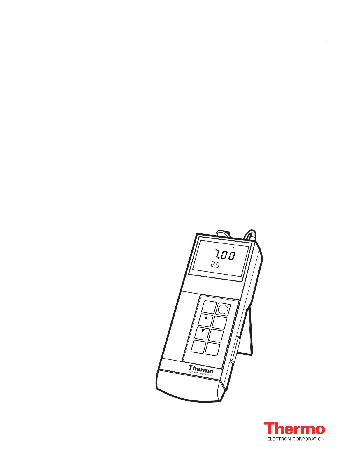
Orion Aplus
Portable pH and ISE Meters
INSTRUCTION MANUAL
C
o
MEASURE
ready
Orion 250A+
setup
power
yes
timer
2nd
no
measure
print
mode
cal
Orion 210A+, 230A+,
250A+, 290A+
Page 2

AQUAfast, Cahn, EZ Flash, Ionalyzer, ionplus, KNIpHE, No Cal, ORION, perpHect, PerpHecT, PerpHecTion, pHISA, pHix, pHuture, Pure Water, Sage, Sensing the Future,
SensorLink, ROSS Ultra, Sure-Flow, TEA Analyzer, Titrator PLUS, TURBO2 and Wine Master are registered trademarks of Thermo Electron Corporation.
1-888-pHAX-ION, A+, All in One, Aplus, AQUAsnap, AssuredAccuracy, AUTO-BAR, AUTO-CAL, AUTO DISPENSER, Auto-ID, AUTO-LOG, AUTO-READ, AUTO-STIR, Auto-Test,
BOD AutoEZ, Cable-Free, CERTI-CAL, CISA, DataCOLLECT, DataPLUS, digital LogR, DirectCal, DuraProbe, Environmental Product Authority, Extra Easy/Extra Value, FAST QC,
Flash Titration, Flash Titrator, GAP, GLPcal, GLPcheck, GLPdoc, ISEasy, KAP, LabConnect, LogR, Low Maintenance Triode, Minimum Stir Requirement, MSR, NISS, One-Touch,
One-Touch Calibration, One-Touch Measurement, Optimum Results, Pentrode, pHuture MMS, pHuture Pentrode, pHuture Quatrode, pHuture Triode, Quatrode, QuiKcheK,
rf link, ROSS, ROSS Resolution, SAOB, Smart CheK, Stacked, Stat Face, The Enhanced Lab, ThermaSense, Triode, TRIUMpH, Unbreakable pH, Universal Access are
trademarks of Thermo.
Guaranteed Success and The Technical Edge are service marks of Thermo.
PerpHecT meters are protected by U.S. patent 6,168,707.
PerpHecT ROSS are protected by U.S. patent 6,168,707.
ORION Series A meters and 900A printer are protected by U.S. patents 5,108,578, 5,198,093, and German patents D334,208 and D346,753.
Sure-Flow electrodes are protected by European Patent 278,979 and Canadian Patent 1,286,720.
ionplus electrodes and Optimum Results solutions are protected by US Patent 5,830,338.
ROSS Ultra electrodes have patents pending.
ORION ORP Standard is protected by US Patent 6,350,367.
ORION Series A conductivity meters are protected by US Patent 5,872,454.
© Copyright 2003, Thermo Electron Corporation. All rights reserved. Question everything, and Analyze. Detect. Measure. Control are trademarks of Thermo Electron
Corporation.
The specifications, descriptions, drawings, ordering information and part numbers within this document are subject to change without notice.
This publication supersedes all previous publications on this subject.
Page 3

Portable pH/ISE Meter Instruction Manual
Ta ble Of Contents
Table Of Contents
Chapter I Introduction . . . . . . . . . . . . . . . . . . . . . . . . . . . . . . . .1
Chapter II General Information . . . . . . . . . . . . . . . . . . . . . . . . .3
A. Top Panel . . . . . . . . . . . . . . . . . . . . . . . . . . . . . . . . . . . . . . . . . . . . .4
B. Rear Panel . . . . . . . . . . . . . . . . . . . . . . . . . . . . . . . . . . . . . . . . . . . .5
C. Electrode Clip . . . . . . . . . . . . . . . . . . . . . . . . . . . . . . . . . . . . . . . . .6
D. Electrode Storage Compartment . . . . . . . . . . . . . . . . . . . . . . . . . .7
E. RS232 Interface . . . . . . . . . . . . . . . . . . . . . . . . . . . . . . . . . . . . . . .8
Chapter III Set Up, Self-Test Procedure . . . . . . . . . . . . . . . . . . .9
A. Power Source . . . . . . . . . . . . . . . . . . . . . . . . . . . . . . . . . . . . . . . . .9
B. Battery Installation . . . . . . . . . . . . . . . . . . . . . . . . . . . . . . . . . . . . .9
C. Power Up and Self-Test . . . . . . . . . . . . . . . . . . . . . . . . . . . . . . . .10
D. Electrode Connections . . . . . . . . . . . . . . . . . . . . . . . . . . . . . . . . .11
Chapter IV Orion 210Aplus . . . . . . . . . . . . . . . . . . . . . . . . . . . .13
A. Display . . . . . . . . . . . . . . . . . . . . . . . . . . . . . . . . . . . . . . . . . . . . . .13
B. Keypad . . . . . . . . . . . . . . . . . . . . . . . . . . . . . . . . . . . . . . . . . . . . . .14
C. Self-Test and Checkout Procedure . . . . . . . . . . . . . . . . . . . . . . .15
D. SETUP Menu . . . . . . . . . . . . . . . . . . . . . . . . . . . . . . . . . . . . . . . .16
Resolution . . . . . . . . . . . . . . . . . . . . . . . . . . . . . . . . . . . . . . . . . . . .16
Slope . . . . . . . . . . . . . . . . . . . . . . . . . . . . . . . . . . . . . . . . . . . . . . . .16
Calibration Buffer Option . . . . . . . . . . . . . . . . . . . . . . . . . . . . . . . .16
E. Calibration and Measurement Procedures . . . . . . . . . . . . . . . . .17
pH Measurements . . . . . . . . . . . . . . . . . . . . . . . . . . . . . . . . . . . . . .17
Autocalibration . . . . . . . . . . . . . . . . . . . . . . . . . . . . . . . . . . . . .17
Manual Calibration . . . . . . . . . . . . . . . . . . . . . . . . . . . . . . . . . .20
F. Dissolved Oxygen Measurements . . . . . . . . . . . . . . . . . . . . . . . .23
Chapter V Orion 230Aplus . . . . . . . . . . . . . . . . . . . . . . . . . . . .25
A. Display . . . . . . . . . . . . . . . . . . . . . . . . . . . . . . . . . . . . . . . . . . . . . .25
B. Keypad . . . . . . . . . . . . . . . . . . . . . . . . . . . . . . . . . . . . . . . . . . . . . .27
C. Self-Test and Checkout Procedure . . . . . . . . . . . . . . . . . . . . . . .29
D. SETUP Menu . . . . . . . . . . . . . . . . . . . . . . . . . . . . . . . . . . . . . . . .30
E. Calibration and Measurement Procedures . . . . . . . . . . . . . . . . .32
pH Measurements . . . . . . . . . . . . . . . . . . . . . . . . . . . . . . . . . . . . . .32
Autocalibration . . . . . . . . . . . . . . . . . . . . . . . . . . . . . . . . . . . . .32
Manual Calibration . . . . . . . . . . . . . . . . . . . . . . . . . . . . . . . . . .35
ORP Relative to Normal Hydrogen Electrode (NHE) . . . . . . . . . . .38
Setting ORP Millivolts Offset . . . . . . . . . . . . . . . . . . . . . . . . . .38
F. Dissolved Oxygen Measurements . . . . . . . . . . . . . . . . . . . . . . . .39
Chapter VI Orion 250Aplus . . . . . . . . . . . . . . . . . . . . . . . . . . . .41
A. Display . . . . . . . . . . . . . . . . . . . . . . . . . . . . . . . . . . . . . . . . . . . . . .41
Page 4

Portable pH/ISE Meter Instruction Manual
Ta ble Of Contents
B. Keypad . . . . . . . . . . . . . . . . . . . . . . . . . . . . . . . . . . . . . . . . . . . . . .43
C. Self-Test and Checkout Procedure . . . . . . . . . . . . . . . . . . . . . . .45
D. SETUP Menu . . . . . . . . . . . . . . . . . . . . . . . . . . . . . . . . . . . . . . . .46
E. Calibration and Measurement Procedures . . . . . . . . . . . . . . . . .49
pH Measurements . . . . . . . . . . . . . . . . . . . . . . . . . . . . . . . . . . . . . .49
Autocalibration . . . . . . . . . . . . . . . . . . . . . . . . . . . . . . . . . . . . .49
Manual Calibration . . . . . . . . . . . . . . . . . . . . . . . . . . . . . . . . . .52
Millivolt Measurements . . . . . . . . . . . . . . . . . . . . . . . . . . . . . . . . .54
ORP Relative to Normal Hydrogen Electrode (NHE) . . . . . . . . . . .55
Setting ORP Millivolts Offset . . . . . . . . . . . . . . . . . . . . . . . . . .55
F. Dissolved Oxygen Measurements . . . . . . . . . . . . . . . . . . . . . . . .56
Chapter VII Orion 290Aplus . . . . . . . . . . . . . . . . . . . . . . . . . . . .57
A. Display . . . . . . . . . . . . . . . . . . . . . . . . . . . . . . . . . . . . . . . . . . . . . .57
B. Keypad . . . . . . . . . . . . . . . . . . . . . . . . . . . . . . . . . . . . . . . . . . . . . .59
C. Self-Test and Checkout Procedure . . . . . . . . . . . . . . . . . . . . . . .61
D. SETUP Menu . . . . . . . . . . . . . . . . . . . . . . . . . . . . . . . . . . . . . . . .63
E. Calibration and Measurement Procedures . . . . . . . . . . . . . . . . .68
pH Measurements . . . . . . . . . . . . . . . . . . . . . . . . . . . . . . . . . . . . . .68
Autocalibration . . . . . . . . . . . . . . . . . . . . . . . . . . . . . . . . . . . . .68
Manual Calibration . . . . . . . . . . . . . . . . . . . . . . . . . . . . . . . . . .69
Concentration Measurements . . . . . . . . . . . . . . . . . . . . . . . . . . . . .72
Millivolt Measurements . . . . . . . . . . . . . . . . . . . . . . . . . . . . . . . . .76
F. Dissolved Oxygen Measurements . . . . . . . . . . . . . . . . . . . . . . . .77
Chapter VIII Temperature Compensation . . . . . . . . . . . . . . . . . .79
Chapter IX Use with Accessories . . . . . . . . . . . . . . . . . . . . . . .81
A. Use with Printers and Computers . . . . . . . . . . . . . . . . . . . . . . . .81
B. Remote Control . . . . . . . . . . . . . . . . . . . . . . . . . . . . . . . . . . . . . . .82
Chapter X Troubleshooting . . . . . . . . . . . . . . . . . . . . . . . . . . .85
A. Self-Test . . . . . . . . . . . . . . . . . . . . . . . . . . . . . . . . . . . . . . . . . . . . .85
B. Operator Assistance Codes . . . . . . . . . . . . . . . . . . . . . . . . . . . . .87
C. Troubleshooting Guide . . . . . . . . . . . . . . . . . . . . . . . . . . . . . . . . .92
Chapter XI Instrument Warranty . . . . . . . . . . . . . . . . . . . . . . . .93
Chapter XII Service and Repair . . . . . . . . . . . . . . . . . . . . . . . . .97
Chapter XIII Notice of Compliance . . . . . . . . . . . . . . . . . . . . . . .99
Chapter XIV Ordering Information . . . . . . . . . . . . . . . . . . . . . . .101
Chapter XV Specification . . . . . . . . . . . . . . . . . . . . . . . . . . . . .103
Page 5

Portable pH/ISE Meter Instruction Manual
Introduction 1
Chapter I
Introduction
Orion’s Portable Meters are compact, battery operated and microprocessor
controlled for all measurement needs. All meters feature a custom digital
LCD display, which simultaneously displays temperature along with
measurement results. Ideal for field, plant, or laboratory use, each meter is
lightweight and designed to fit comfortably in the hand.
A flip stand allows easy use in the lab.
The Orion 210Aplus is a basic pH meter that features 2 point
autocalibration.
The Orion 230Aplus is a pH meter that features autocalibration and
automatic temperature compensation, millivolt, relative millivolt and (E
H
)
ORP mode.
The Orion 250Aplus has all the features of the 230Aplus plus 3 point auto
calibration and RS232-C output for use with the Orion 900A printer or
other serial peripherals.
The Orion 290Aplus adds concentration measurements and an internal
datalogging function to make a truly versatile meter for pH or ISE analysis.
This manual contains instructions for all four meters. See the calibration
and measurement section for details on your particular meter. The general
information section contains descriptions of hardware which pertain to all
meters. The Temperature Compensation and Troubleshooting sections
contain information applicable to all meters.
Page 6

Portable pH/ISE Meter Instruction Manual
2
Page 7
Portable pH/ISE Meter Instruction Manual
General Information 3
Chapter II
General Information
Orion’s Portable Meters have a large custom LCD display and keypad with
tactile and audible feedback. Designed for one-handed operation each
features an electrode clip to attach electrode directly to meter and molded
grip area. (Electrode clips included in Portable Meter Starter Kit, Orion
No. OPBLSK)
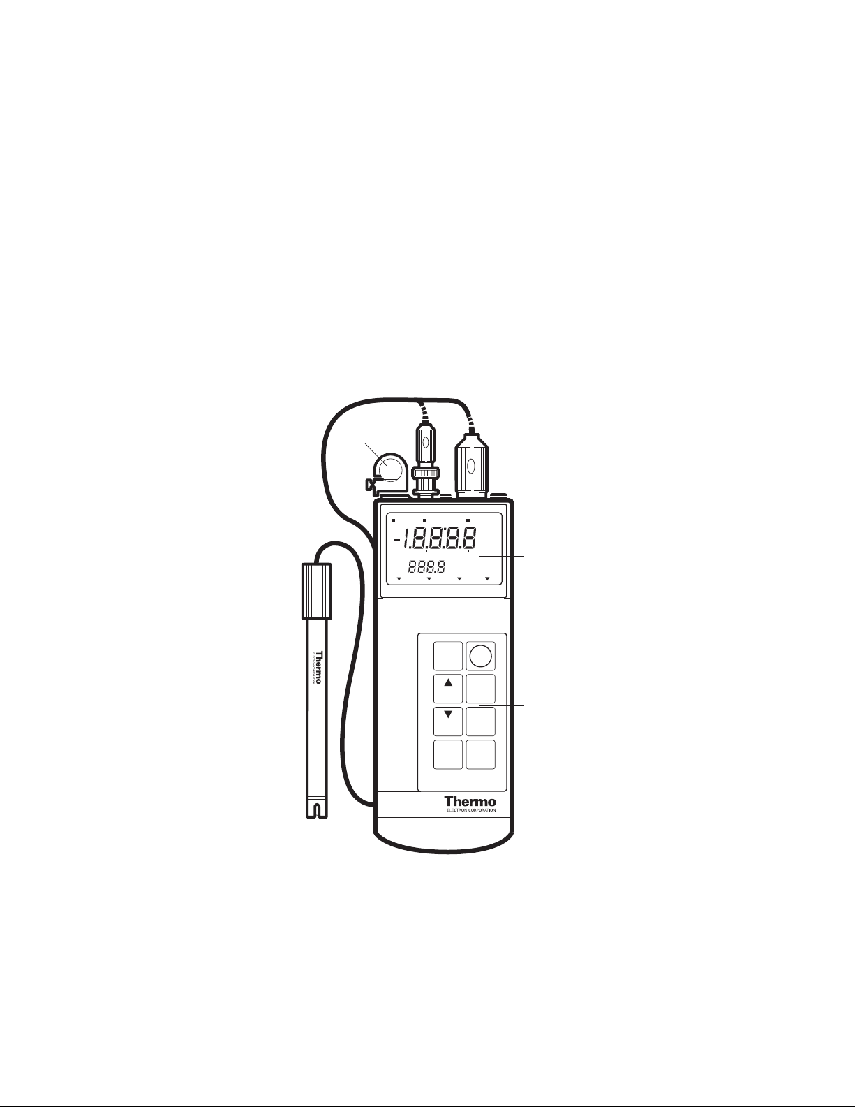
Figure 1: Front Panel Orion 250Aplus
Electrode Clip
SETUP CALIBRATE MEASURE
ON
OFF
pH mV Rel mV E
EXP
˚C
ATC
yes
timer
setup
power
Orion 250A+
2nd
ready
hold
timer
bat.
no
measure
print
mode
cal
2nd
H
LCD Display
Keypad
Page 8
Portable pH/ISE Meter Instruction Manual
General Information4
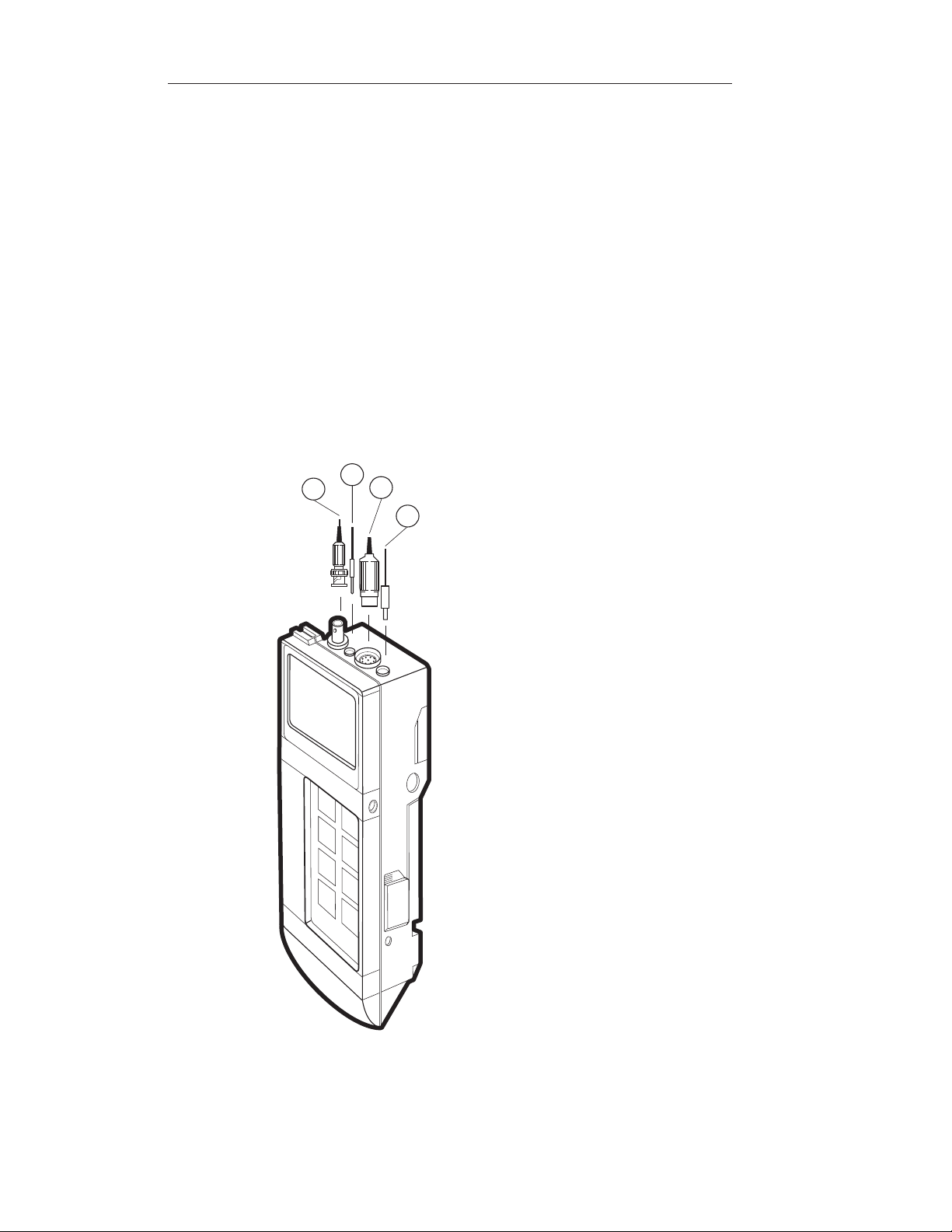
A. Top Panel
1. Electrode Connections: Accepts BNC connector from combination or
half-cell sensing electrode(s) (1A). A separate pin tip (1B) accepts a
reference electrode.
2. ATC Probe Jack: Accepts thermistor type Automatic Temperature
Compensation probe with DIN connector.
3. Line Converter Jack: Accepts an AC line converter for use without
batteries.
1A
1B
2
3
Figure 2: Top Panel Orion 250Aplus
Page 9
Portable pH/ISE Meter Instruction Manual
General Information 5
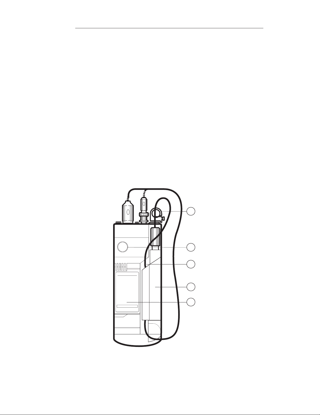
B. Rear Panel
1. Battery Compartment: Accepts one 9 V battery, either alkaline
or lithium.
2. Setup Menu Label: Identifies setup parameters and corresponding
I.D. codes.
3. Electrode Clip: Attaches an electrode directly to the meter for onehanded operation.
4. Electrode Storage Compartment: Stores electrode in between
measurements. Compartment can contain electrode storage solution to
keep electrode moist and ready for use.
5. Cable Management: The cable(s) from the electrode(s) will slide under
the left side of the storage compartment.
Figure 3: Rear Panel Orion 250Aplus
Orion 250A
SETUP:
1-1 READY
1-2 HOLD
1-3 BEEP
1-4 SHUTOFF
2-1 SLOPE
3-1 TIMER INTERVAL
3-2 REMAINING TIME
S/N 000000
© 2003 Thermo Electron Corporation
MADE IN USA
3
1
5
4
2
Page 10
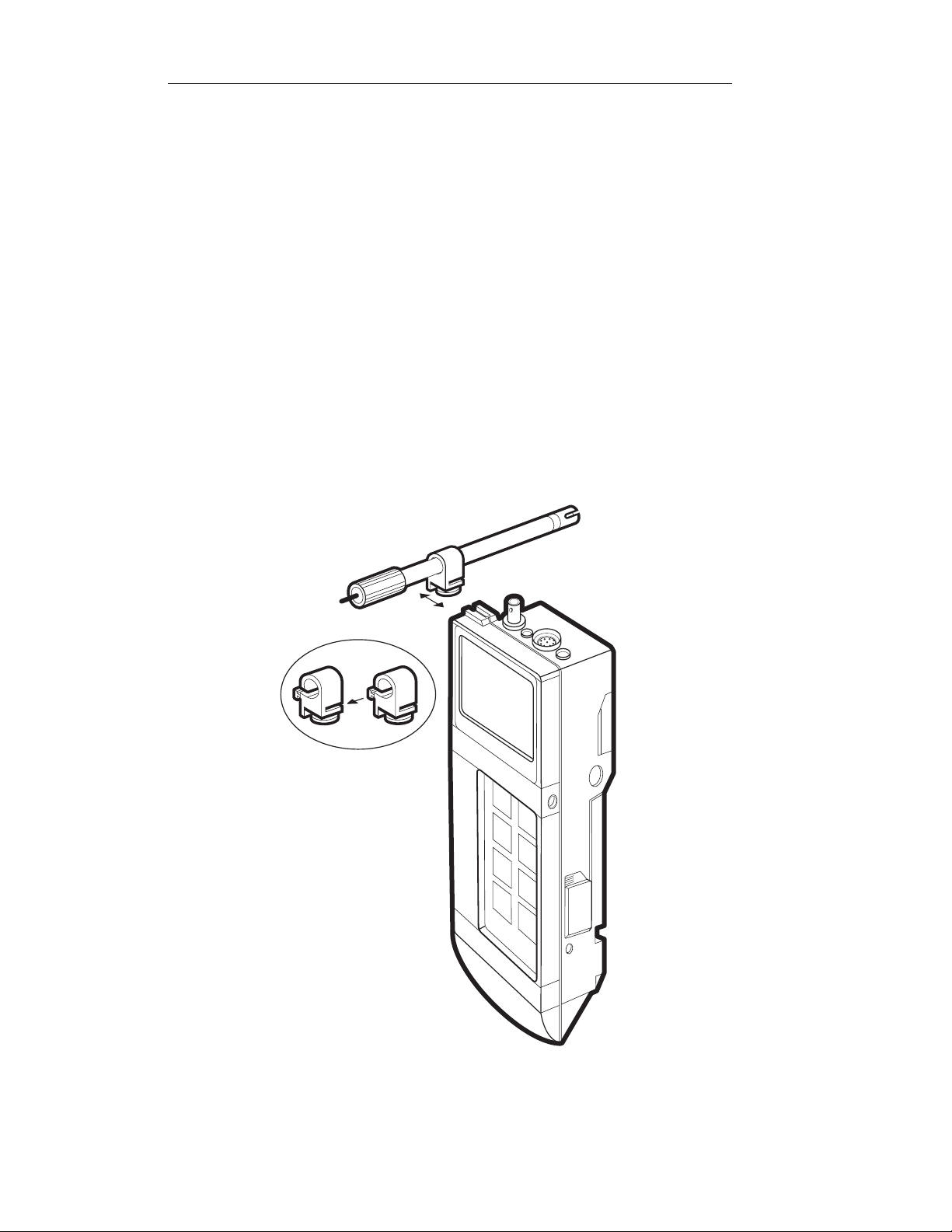
C. Electrode Clip
The electrode clip allows easy one-handed dip and read operation. Two or
more electrodes may be joined together and then attached directly to
the meter.
1. Slide electrode clip onto electrode.
2. If using two electrodes, slide second electrode clip into opening on the
first electrode clip (see illustration).
3. Attach electrode(s) to meter by sliding clip from left to right into meter
until securely seated.
Portable pH/ISE Meter Instruction Manual
General Information6
Figure 4: Electrode Clip
Page 11
Portable pH/ISE Meter Instruction Manual
General Information 7
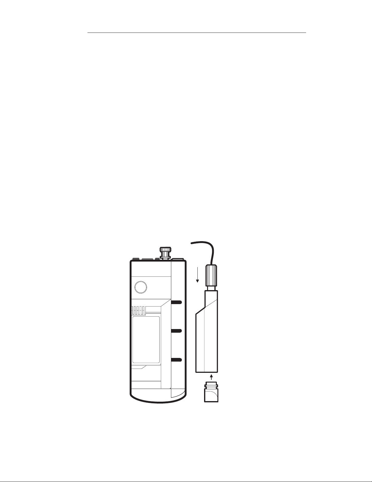
D. Electrode Storage Compartment
The electrode storage compartment provides a convenient place for
electrode storage between measurements and in the field. Add a few drops
of pH electrode storage solution Orion No. 910001 to the storage
compartment cap to ensure your electrode will be ready for use. The entire
compartment is removable for easy cleaning.
The right-hand side of the compartment (when the meter is turned over and
facing down) provides a space for the electrode cables. Slide the cable
underneath the edge of the compartment.
1. With the meter facing down slide the compartment to the right
to remove.
2. Rinse with distilled or deionized water.
3. Replace compartment by lining up pins on meter with slides on
electrode storage compartment then slide to the left until firmly
in place.
Figure 5: Electrode Storage Compartment
Page 12

Portable pH/ISE Meter Instruction Manual
General Information8
E. RS232-C Interface
Both the Orion 250Aplus and 290Aplus have an RS232-C interface for use
printers or serial peripherals.
The Orion 250Aplus has a one way interface for communication with the
Orion 900A printer or other device. The instrument can send (but not
receive) information via this port.
The Orion 290Aplus has a bi-directional interface for communication with
printers or computers. The instrument can send or receive information
using this port.
The Orion 900A printer is battery operated and attaches directly to either
meter making a compact package for field measurement and recording.
See printer manual, part no. 213377-001.
Page 13
Portable pH/ISE Meter Instruction Manual
Set Up and Self-Test Procedures 9
Chapter III
Set Up and Self-Test Procedures
A. Power Source
The Orion Portable Meters operate on either one 9V alkaline battery, one
9V lithium battery, or an AC line adapter. The estimated battery life is 50
hours of continuous operation for an alkaline battery and 100 hours of
continuous operation for a lithium battery. Insert battery as described below
or plug in the line adapter.
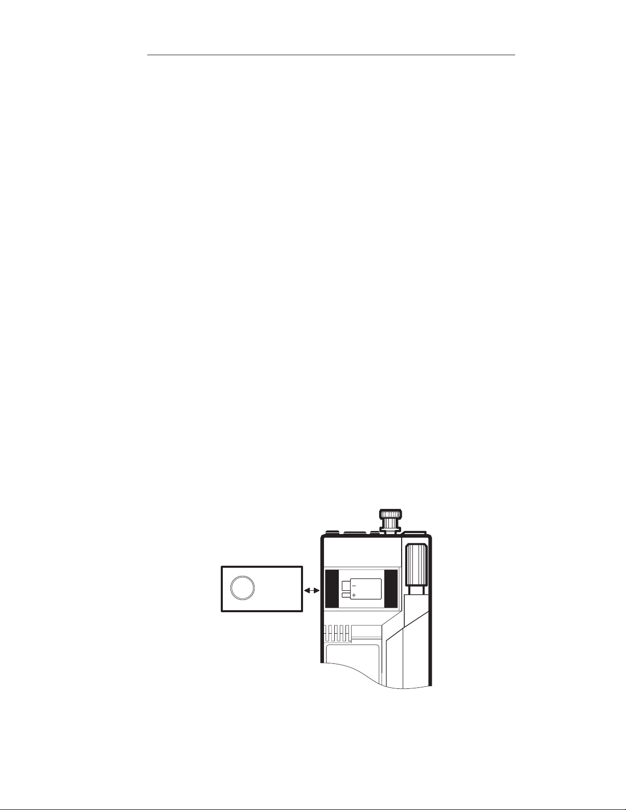
B. Battery Installation
1. Open battery compartment by pushing closure up. This is most easily
accomplished by using a coin (such as a dime) and inserting it into the
slot on the side of the meter.
2. Insert battery pushing gently until it locks in place. Ensure polarity is
correct as shown in the battery compartment.
3. Replace battery compartment cover.
NOTE: After replacing the battery, recalibrate meter. Without
the battery installed or meter plugged into line power, the meter
loses calibration data and other information in memory. To
prevent loss of data in the field, turn meter off if the low battery
signal comes on. Check and replace batteries regularly prior to
field use.
Figure 6: Battery Compartment
Page 14

Portable pH/ISE Meter Instruction Manual
Set Up and Self-Test Procedures10
C. Power Up and Self-Test
NOTE: Use this procedure when the instrument is first received
and whenever troubleshooting becomes necessary.
1. Attach the BNC Shorting Plug (Orion No. 090045) to BNC connector
on top of meter.
2. Press the power key to turn meter on.
3. If battery indicator remains on, replace battery or use line adapter.
4. Press the power key to turn meter off.
5. Press the power key and quickly press the yes key to start the self-test.
(Alternatively, press and hold the yes key while pressing the power
key). The instrument automatically performs electronic and hardware
diagnostic tests. For a more detailed explanation, see the self-test
section of the troubleshooting guide.
6. When the code 7 appears in the lower display field, “0” will be
displayed, press each key, including the power key, one at a time. A
numeric digit will be displayed upon each key press.
NOTE: All keys must be pressed within 10 seconds to complete
test 7.
7. For Orion 210Aplus or Orion 230Aplus: After the keypad test, the
meter will shut off.
For Orion 250Aplus or Orion 290Aplus: After the keypad test, the
meter will turn off then back on again. After completing the self-test,
the meter will resume normal operation.
8. If any problems are found during self-test, the meter will display the
operator assistance code until acknowledged by pressing the yes key.
See Troubleshooting section.
Page 15

Portable pH/ISE Meter Instruction Manual
Set Up and Self-Test Procedures 11
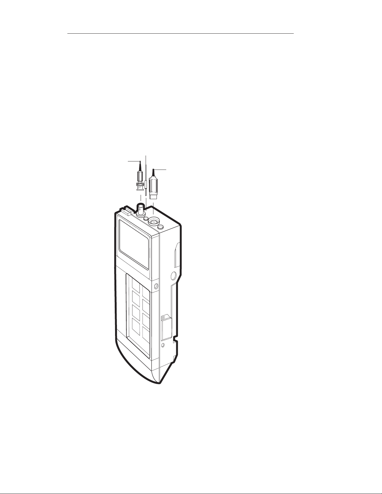
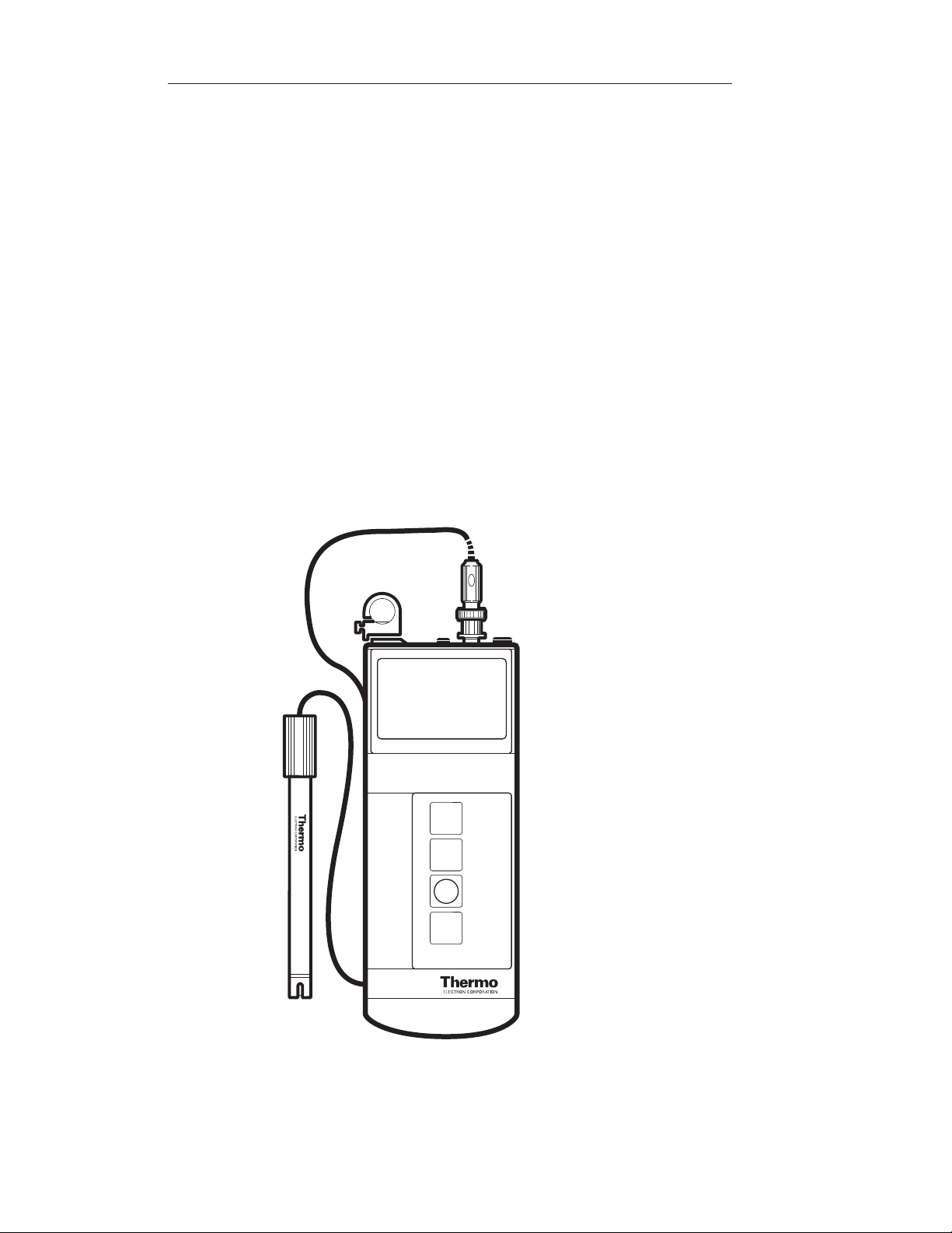
D. Electrode Connections
Orion Triode
Attach Orion TRIODE electrode by sliding the BNC connector onto the
sensor input then push down and turn clockwise to lock into position. Slide
the DIN connector into the ATC jack until it is firmly seated.
Other Electrodes
Attach electrodes with BNC connectors to sensor input by sliding
connector onto input, pushing down and turning clockwise to lock into
position. Connect reference electrodes with pin tip connectors by pushing
connector straight into reference input.
NOTE: If using a combination electrode with a BNC
connector, the reference pin-tip is not used.
Page 16
Portable pH/ISE Meter Instruction Manual
Set Up and Self-Test Procedures
12
ATC Probe
Attach the ATC probe to the ATC jack by sliding the connector straight on
until firmly in place. The connector has a special sealing mechanism, which
is engaged when the connector is properly attached, to prevent moisture
from penetrating the meter.
Figure 7: Electrode Connections
Pin Tip
BNC
ATC
Page 17
Portable pH/ISE Meter Instruction Manual
Orion 210Aplus 13
Chapter IV
Orion 210Aplus
A. Display
Operating Mode Indicates instrument operating mode.
SETUP Indicates meter is in setup mode. Used to define
operating parameters.
CALIBRATE Indicates meter is in calibration mode.
MEASURE Indicates meter is in measurement mode.
Main Field Displays pH readings, electrode slope and other
significant information.
Lower Field Displays temperature in degrees Celsius. The ˚C
designation is displayed when temperature is
displayed.
AT C Displayed when a temperature probe is attached.
READY Displayed when the electrode signal has stabilized.
The Ready function may be turned on or off in the
setup menu.
BAT Displayed when the battery is low and needs to be
replaced.
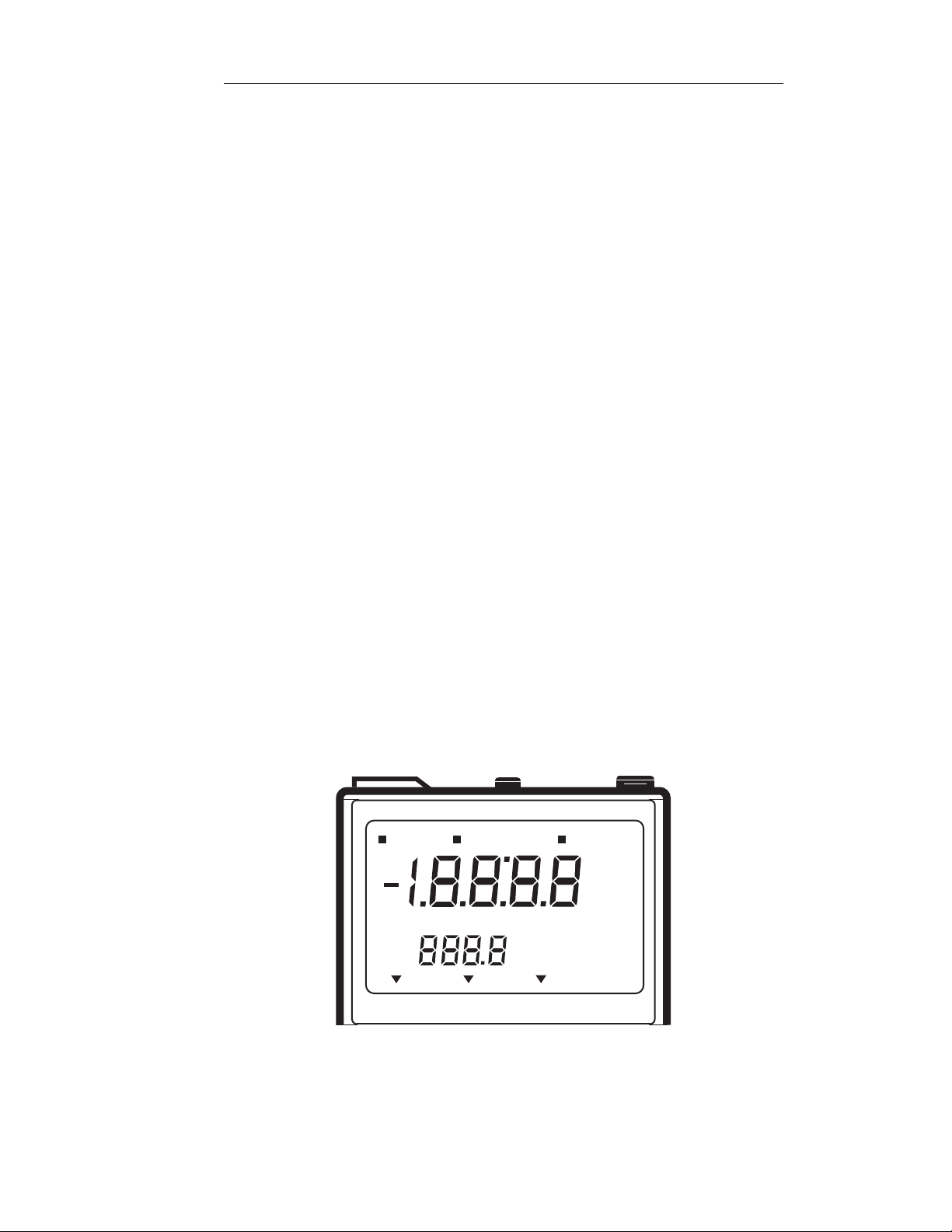
Figure 8: 210Aplus Display
SETUP CALIBRATE MEASURE
ready
˚C
ATC
bat.
4 7 10
Page 18
Portable pH/ISE Meter Instruction Manual
Orion 210Aplus14
B. Keypad
yes Press to enter a value during calibration or setup. May also
be used to scroll through the setup menu without changing
any parameters.
no Press to cancel a change to a parameter before entering.
May also be used to initiate a change in current setup
parameter.
mode Press to select operating mode: SETUP, CALIBRATE
or MEASURE.
power Press to turn meter on or off.
power
4 7 10
no
mode
yes
Orion 210A+
Figure 9: 210Aplus Keypad
Page 19

Portable pH/ISE Meter Instruction Manual
Orion 210Aplus 15
C. Self Test and Checkout Procedure
This procedure should be performed when the meter is received and when
operation problems arise. This procedure verifies the proper operation of
the Orion 210Aplus Meter.
1. Attach the Orion shorting cap to the meter.
2. Press the power key to turn meter on.
3. If the low battery indicator remains on, replace the battery or use a line
adapter.
4. Press the power key to turn meter off.
5. Press the power key and quickly press the yes key to start the self-test.
The meter automatically performs electronic and hardware diagnostic
tests.
6. When the code 7 appears in the lower display field, “0” will be
displayed, press each key, including the power key, one at a time. A
numeric digit will be displayed upon each key press.
7. After the self-test is complete, the meter will automatically shut off. To
restart the meter, press the power key.
8. If any problems are found during the self-test, the meter will beep and
an operator assistance code will be displayed until acknowledged by
pressing the yes key. See Troubleshooting.
Page 20

Portable pH/ISE Meter Instruction Manual
Orion 210Aplus16
D. SETUP Menu
Select SETUP mode by pressing the mode key until SETUP is displayed.
The SETUP mode is used to define, change or view meter operating
parameters. While in the SETUP mode, the yes key is used to scroll through
the menu without changing parameters and to enter new parameters into
meter memory. The no key is used to scroll through options within each
parameter. To exit the SETUP mode, press the mode key at any time.
The following parameters are accessed in the SETUP mode:
Resolution
The current pH resolution will be displayed. The default setting is two
decimal places (i.e. pH 7.00). Press the yes key to agree with setting or
press the no key to change to 7.0 and then press the yes key to accept the
new setting.
Slope
The current electrode slope in meter memory will be displayed. The value
is displayed as a percent of theoretical slope. The default setting is 100%.
This function is for display purposes only. The value can not be changed in
the SETUP menu. To change the slope value, perform a two buffer
calibration or set slope during a one buffer calibration. Press the yes key to
advance to next menu option.
Cal. Buffer Option
The current calibration buffer option in meter memory will be displayed as
STD “570” or SET “5E7” on the temperature display.
Auto Calibration Buffer Option
When the “570” option is selected, calibration may only be performed with
standard buffers: pH 4.01, 7.00 and 10.01.
Manual Calibration Buffer Option
When the “5E7” option is selected, calibration may be performed with user
defined buffers within the range of 0 to 14 pH.
NOTE: The chosen buffers must be greater than one (1) pH unit
but less than four (4) pH units from each other.
Page 21

Portable pH/ISE Meter Instruction Manual
Orion 210Aplus 17
E. Calibration and Measurement Procedures
pH Measurements
A one or two buffer calibration should be performed before pH is
measured. It is recommended that a two buffer calibration, using buffers
that bracket the expected sample range, be performed at the beginning of
each day to determine the slope of the electrode. This serves the dual
purpose of determining if the electrode is working properly and storing the
slope value in memory. Perform a one buffer calibration every two hours to
compensate for electrode drift.
Prior to calibration, scroll through the setup menu and ensure all
parameters are set correctly for the analysis you want to perform.
There are two ways of calibrating the 210Aplus Meter: autocalibration or
manual calibration. Following are descriptions and instructions for each
method.
Autocalibration
Autocalibration is a feature of the Orion 210Aplus Meter that
automatically recognizes the buffers 7.00, 4.01 and 10.01 within a range of
(0.5 pH units. Simply select the buffer sequence that best fits your
application, choose between, 7 - 10; 7 - 4; or a one point autocalibration
with pH 7. During calibration wait for READY to be displayed, indicating
electrode stability. Once the electrode is stable, the meter automatically
recognizes and displays the temperature-corrected value for that buffer.
Press the yes key to enter the value into memory.
The 210Aplus Meter compares actual values to theoretical values to
determine if the buffer is within range. Results greater than (0.5 pH units
from the theoretical value will trigger an operator assistance code. For best
results, it is recommended that an ATC probe be used. If an ATC probe is
not used all samples and buffers should be at the same temperature or
manual temperature compensation should be used.
Page 22

Portable pH/ISE Meter Instruction Manual
Orion 210Aplus18
Autocalibration with Two Buffers
1. Connect the electrode(s) to meter. Choose either 4.01 and 7.00, or 7.00
and 10.01 buffers, whichever will bracket your expected sample range.
2. Rinse the electrode(s) and place into the 7.00 buffer.
3. Press the mode key until CALIBRATE is displayed above the main
readout. The last buffer sequence used will be displayed. Press the yes
key to use this sequence, or press the no key to scroll through other
choices, and then press the yes key when the desired sequence is
displayed.
4. The buffer indicator along the bottom of the display will indicate the
buffer chosen. P1 will be displayed in lower display field and buffer
reading will be displayed in the main field.
5. When READY is displayed, indicating electrode stability, the
temperature-corrected value for the buffer is displayed. Press the yes
key. The display will remain frozen for two seconds. Then P2 is
displayed in the lower field indicating the meter is ready for the second
buffer. The buffer indicator along the bottom of the display will
indicate the second buffer of the calibration sequence selected.
6. Rinse the electrode(s) and place into the second buffer.
7. When READY is displayed, indicating electrode stability, the
temperature-corrected value for the buffer is displayed. Press the yes
key. The display will remain frozen for two seconds.
8. After the second buffer value has been entered, the electrode slope will
be displayed. SLP appears in the lower field while the actual electrode
slope (in percent) appears in the main field for 5 seconds.
9. The meter will then automatically advance to the measure mode and
MEASURE is displayed above the main display field.
10. Rinse the electrode(s) and place into the sample. Record pH and
temperature directly from the meter display.
Page 23

Portable pH/ISE Meter Instruction Manual
Orion 210Aplus 19
Autocalibration with One Buffer
NOTE: Autocalibration with one buffer can only be performed
using buffer 7.00
1. Attach the electrode(s) to the meter.
2. Rinse the electrode(s) and place into 7.00 buffer.
3. Press the mode key until CALIBRATE is displayed above the main
readout. The last buffer sequence used will be displayed. Press the no
key until 7 is displayed. Then press the yes key.
4. The buffer indicator along the bottom of display will indicate the
buffer selected (7) and P1 will be displayed in the lower field. The
buffer reading will be displayed in the main field.
5. When READY is displayed, indicating electrode stability, press the yes
key. The temperature-corrected value for that buffer is entered into the
memory of the meter.
6. SLP will appear in the lower display field and the current electrode
slope in memory is displayed in the main field. Press the yes key to
accept value or press the no key to change value. The value in the
main display will blink. Begin editing with the left most digit.
Pressing the no key will scroll the value. Set digit to desired value and
press the yes key. Continue editing each digit until desired slope value
is entered into memory.
7. The meter will then automatically advance to the measure mode and
MEASURE is displayed above the main display field. Rinse the
electrode(s) and place into sample. Both the temperature-corrected pH
reading and temperature reading are displayed. Record reading when
READY is displayed.
Page 24

Portable pH/ISE Meter Instruction Manual
Orion 210Aplus20
Manual Calibration
Manual Calibration with Non-Standard Buffers
The Orion 210Aplus Meter features a manual calibration option when the
use of non-standard buffers is required for calibration. Simply enter the
values of the buffers to be used into the memory of meter in the SETUP
menu. For best results, buffer values entered must be the value of the
buffers at the temperature at which calibration is being performed. Once
these values have been entered, SET (5E7) will appear in the buffer
sequence selections. Select SET and the meter will automatically recognize
the buffer values which were entered in the SETUP menu. These values
will remain in the meter memory until new values are entered.
NOTE: The calibration buffers should be used during the
calibration in the same sequence as they are entered in the
SETUP mode.
Page 25

Portable pH/ISE Meter Instruction Manual
Orion 210Aplus 21
Setting the Manual Buffer Option
Two non-standard buffer values may be set for use in performing
calibrations. The manual buffer pH range is 0 - 14. After these values have
been entered into the memory of the meter, the meter will automatically
use these values during calibration whenever the SET option is selected
during buffer sequence selection at the start of calibration.
NOTE: The difference between the two non-standard buffers
must be at least 1 pH unit and no more than 4 pH units.
1. Select the SETUP mode, by pressing the mode key repeatedly until
SETUP is displayed. Press the yes key twice.
2. STD (570) will be displayed. Press the no key. SET (5E7) will be
displayed. Press the yes key.
3. The value in the main display will blink and P1 will be displayed in
the lower display indicating that the first buffer value is being set.
4. Begin editing with the digit furthest to the left. Press the no key to
scroll the value between 0 and 1. Set digit to desired value and press
the yes key.
5. Continue editing the value for each digit until the desired buffer value
has been entered then press the yes key to enter the buffer value into
the meter memory.
6. The value in the main display will blink and P2 will be displayed in
the lower display indicating that the second buffer value is being set.
7. Begin editing the value for each digit until the desired buffer value has
been entered and press the yes key to enter the buffer value into the
meter memory.
8. The meter will automatically return to the beginning of the SETUP
menu. Press the mode key to exit the SETUP menu.
Page 26

Portable pH/ISE Meter Instruction Manual
Orion 210Aplus22
Manual Calibration with Two Buffers
1. Attach the electrode(s) to the meter. Choose two buffers that will
bracket your expected sample range.
2. Rinse the electrode(s) and place into the first buffer.
3. Enter the non-standard buffer values into meter memory as described
in Setting Manual Buffer Option, page 21 .
4. Select calibration mode by pressing the mode key repeatedly until
CALIBRATE is displayed.
5. The last buffer sequence used will be displayed for 2 seconds. If SET
is displayed press the yes key, otherwise press the no key repeatedly
until SET is displayed. Then press the yes key.
6. The buffer indicator along the bottom of the display will show MAN
indicating manual buffer option selected. P1 will be displayed in the
lower display field and the buffer reading will be displayed in the main
field.
7. When READY is displayed, indicating electrode stability, press the yes
key. P2 will be displayed in the lower display field indicating the meter
is ready for the second buffer.
8. Rinse the electrode(s) and place into the second buffer.
9. When READY is displayed, press the yes key.
10. After the second buffer value has been accepted, the electrode slope
will be displayed. SLP appears in the lower field while the actual
electrode slope (in percent) is displayed in the main field for 5 seconds.
The meter will then automatically advance to the measure mode and
MEASURE is displayed above the main display field. The buffer
indicator, indicates MAN, manual buffer calibration option was used in
the last calibration.
11. Rinse the electrode(s) and place into the sample. If using an ATC
probe, then both the temperature-corrected pH reading and temperature
reading are displayed. Record the reading when READY is displayed.
For best results, it is recommended that an ATC probe be used. If an
ATC probe is not used, all samples and standards should be at the same
temperature or manual temperature compensation should be used.
Page 27

Portable pH/ISE Meter Instruction Manual
Orion 210Aplus 23
F. Dissolved Oxygen Measurements
Dissolved oxygen measurements are displayed in ppm when the
Orion 97-08 Dissolved Oxygen Electrode is used with the Orion 210Aplus
Meter. Follow these instructions for preparing the meter and calibrating
the electrode.
1. Connect the Orion 97-08 to meter and leave electrode mode switch
“OFF”.
2. Disconnect the ATC probe.
NOTE: ATC probe must not be connected to the meter
3. While in MEASURE mode, use the no key to change the temperature
value to 25.0 ˚C.
4. Press the mode key repeatedly until CALIBRATE is displayed. The
last buffer sequence used will be displayed. Press the no key until 7 is
displayed, then press the yes key.
5. When READY is displayed, indicating electrode stability, press the
yes key.
6. SLP will appear in the lower display field and the current electrode
slope in memory is displayed in the main field. Press the no key to
change value to 100.0, then press the yes key.
7. The meter will then automatically advance to the measure mode and
MEASURE is displayed above the main display field.
8. Turn the mode switch on the electrode to BT CK. Good battery
operation is indicated by a reading of 13.40 or greater on the meter.
9. Turn the mode switch on the electrode to ZERO. Use the zero
calibration control to set the meter to read 0.00.
Page 28

10. Insert the reservoir (funnel) into a BOD bottle containing enough water
to just cover the bottom. Insert the electrode, making sure that the
electrode tip is not immersed in the water and does not have water
droplets clinging to the outside of the membrane. Let stand
approximately 30 minutes to ensure water saturation of air in the BOD
bottle. This bottle should be used for storage between measurements.
11.Turn the electrode mode switch to the AIR position. If measurements
are being made at sea level use the AIR calibration control on the
electrode to set the pH meter reading to the prevailing barometric
pressure in mm Hg (divided by 100). If the barometric pressure is
unknown, if the elevation is above sea level or if the sample has a
salinity greater than 2 parts per thousand, consult Table 1 found in the
Orion 97-08 Instruction Manual to obtain the correct AIR setting.
12. Turn the electrode mode switch to H
2
O for sample analysis.
Portable pH/ISE Meter Instruction Manual
Orion 210Aplus24
Page 29
Portable pH/ISE Meter Instruction Manual
Orion 230Aplus 25
Chapter V
Orion 230Aplus
A. Display
Operating Mode Indicates instrument operating mode.
SETUP Indicates meter is in setup mode. Used to define
operating parameters.
CALIBRATE Indicates meter is in calibration mode. Accessed
by pressing the 2nd then cal keys.
MEASURE Indicates meter is in measurement mode. Accessed
by pressing the measure key.
Main Field Displays pH readings, electrode slope and other
significant information depending on the meter
operating mode.
ON/OFF Indicates if a particular feature is active or not in
the SETUP menu.
Lower Field Displays temperature in degrees Celsius. The ˚C
designation is displayed when temperature is
displayed.
AT C Displayed when a temperature probe is attached.
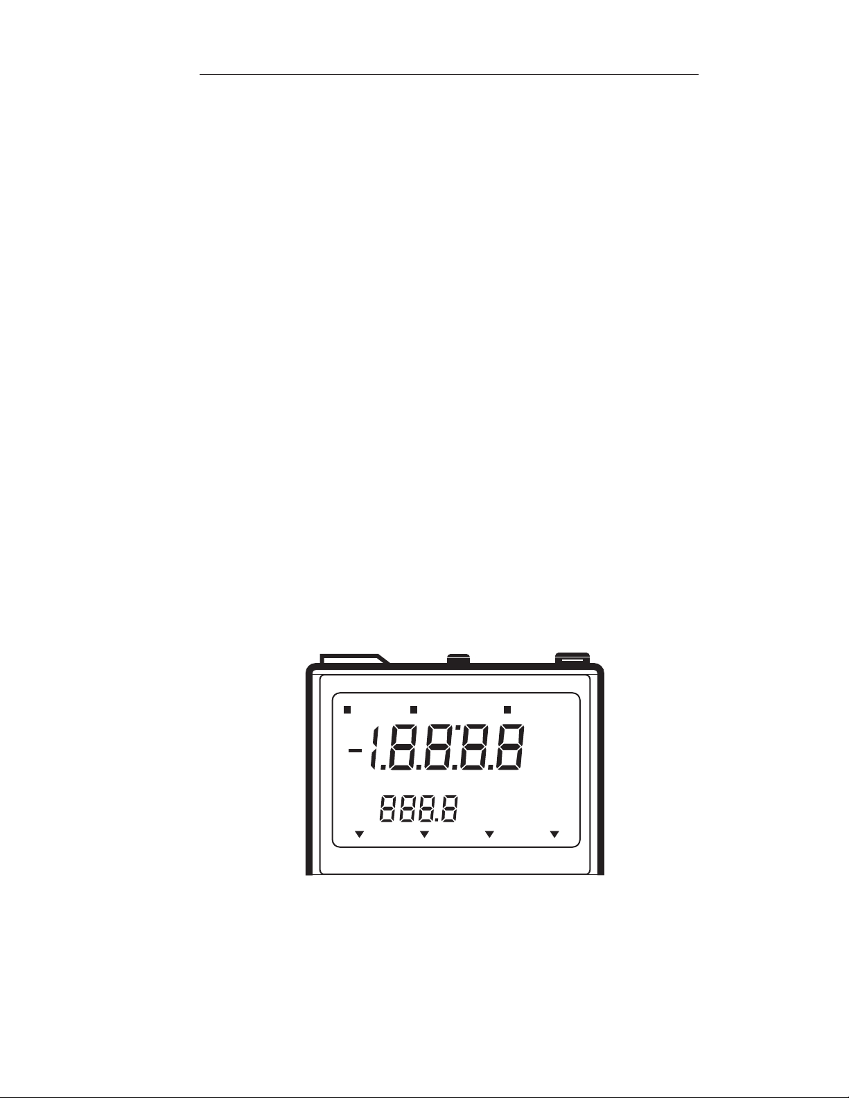
Figure 10: 230Aplus Display
SETUP CALIBRATE MEASURE
2nd
ready
hold
ON
OFF
˚C
ATC
pH mV Rel mV
timer
bat.
E
H
Page 30

Portable pH/ISE Meter Instruction Manual
Orion 230Aplus26
2nd Displayed when the 2nd key has been pressed,
indicating the meter is ready to perform a
secondary function.
READY Displayed when the electrode signal has stabilized.
The READY function may be turned on or off in
the setup menu.
HOLD Displayed when the pH reading is frozen after
reaching stability in measure mode. The HOLD
feature may be turned on or off in the SETUP
menu.
TIMER Displayed when the timer function has been
activated.
BAT Displayed when the battery is low and needs to be
replaced.
Mode Indicator Designates instrument measurement mode either
pH, millivolts (mV) or Relative millivolts (Rel
mV) or ORP Relative to Normal Hydrogen
Electrode (NHE).
Page 31

Portable pH/ISE Meter Instruction Manual
Orion 230Aplus 27
B. Keypad
Primary Functions
yes Press to enter a value during calibration or setup. May also
be used to scroll through the setup menu without changing
any parameters.
no Press to cancel a change to a parameter before entering.
measure Press for sample analysis. Instrument will remain in
measure mode until another key is pressed. Press to unlock
hold.
2nd Press to access second functions: timer, cal or setup menu.
Press to increase value.
Press to decrease value.
power Press to turn meter on or off.
mode Press to change measurement modes. The options are pH,
mV, Rel mV, or E
H
.
▼
▼
Page 32

Portable pH/ISE Meter Instruction Manual
Orion 230Aplus28
Second Functions
All second functions are accessed by first pressing the 2nd key.
timer Press to start the timer. When the preset time has elapsed the
instrument will beep for 1 minute (or until a key is pressed).
setup Press to access the setup menu. This is used for setting
instrument operating parameters.
cal Press to start calibration. Meter automatically advances to
measure after the calibration is complete.
setup
power
pH mV Rel mV E
H
yes
timer
2nd
no
measure
mode
cal
Orion 230A+
Figure 11: 230Aplus Keypad
Page 33

Portable pH/ISE Meter Instruction Manual
Orion 230Aplus 29
C. Self Test and Checkout Procedure
1. Attach the BNC Shorting Plug (Orion No. 090045) to BNC connector
on top of meter.
2. Press the power key to turn meter on.
3. If battery indicator remains on, replace battery or use line adapter.
4. Press the power key to turn meter off.
5. Press the power key and quickly press the yes key to start the self-test.
(Alternatively, press and hold the yes key while pressing the power
key). The instrument automatically performs electronic and hardware
diagnostic tests. For a more detailed explanation, see the self-test
section of the Troubleshooting guide.
6. When the code 7 appears in the lower display field, “0” will be
displayed, press each key, including the power key, one at a time. A
numeric digit will be displayed upon each key press.
NOTE: All keys must be pressed within 10 seconds to complete
test 7.
7. After the keypad test, the meter will shut off. After completing the
self-test, the meter will resume normal operation.
8. If any problems are found during self-test, the meter will display the
operator assistance code (for details, see page 83) until acknowledged
by pressing the yes key.
9. Press the power key to turn meter on. Press the measure key. Main
display should read a steady 7.00 ± 0.02. If not, follow steps 9a
through 9b.
a. Press the cal key, when the display flashes 7.00, press the yes key.
b. Press the measure key. The main display should read 100.0, with
the legend SLP, in the lower display. If so, press the yes key. If not,
scroll until the display reads 100.0, then press the yes key. The
meter advances to measure and the display should now read a
steady 7.00.
10. The meter is now ready for use with a pH electrode. Remove the
shorting plug.
Page 34

Portable pH/ISE Meter Instruction Manual
Orion 230Aplus30
D. SETUP Menu
The SETUP menu is used to identify and change instrument operating
parameters. While in SETUP, the yes key is used to scroll through the
menu without changing any parameters. To change a parameter, press one
of the scroll keys, or , then the yes key to enter the change into the
meter memory. Pressing the no key restores the parameter to its former
state (if done before entering the new setting).
To enter the SETUP menu, press the 2nd then the setup keys. 1-1 and
READY will be displayed. The ON or OFF indicator will flash indicating
the current status. Press the yes key to accept and continue through the
menu. Press a scroll key, or , to change. After changing a setting, press
the yes key to enter into the meter memory.
To change a numeric value, press the or key. The first digit will start
flashing, scroll until the first digit is the desired value, then press the yes
key to accept. The second digit will flash. Scroll until the desired value is
displayed, then press the yes key to accept. Continue in this manner until
all digits have been changed to the desired value, then press the yes key to
enter into the meter memory.
Scroll through the SETUP menu accepting or changing parameters as
desired. To exit the SETUP menu, press the cal key to begin the
CALIBRATION sequence or press the measure key to analyze samples.
The following parameters are accessed in the SETUP menu.
1-1 READY Turning READY on will cause the ready indicator
to be displayed when the electrode signal is stable.
It is always on during calibration and when hold is
turned on. The default setting is on.
1-2 HOLD Turning HOLD on will cause the display to freeze
during sample measurements when the electrode
signal is stable. Press the measure key to unlock
HOLD during analysis. The default setting is off.
1-3 BEEP Turning BEEP on will cause an audible signal to
sound when a key is pressed, when the electrode
signal is stable (on ready), and when an operator
assistance code is displayed. The default setting
is on.
▼
▼
▼
▼
▼
▼
Page 35

Portable pH/ISE Meter Instruction Manual
Orion 230Aplus 31
1-4 AUTO- Turning AUTOSHUTOFF on will cause the meter
to turn off if no keys have been pressed for 10
minutes. This feature will save battery life. The
default setting is on.
2-1 SLOPE Allows review of electrode slope in memory at
any time. Value cannot be changed in the SETUP
menu.
3-1 TIMER Used to set the timer interval. The maximum
interval that can be set is 23 hours, 59 minutes and
59 seconds. The minimum interval is five (5)
seconds. When the TIMER INTERVAL code,
(3-1), is displayed, the current interval hours
setting is first displayed in the main field (H 00).
Press the yes key to accept the current setting or
scroll to the desired value, then press the yes key
to accept. Next, the current interval
minutes:seconds will be displayed. Press the yes
key to accept or scroll to the desired value then
press the yes key. The default setting is five
seconds.
3-2 TIME Allows review of the time remaining before the
TIMER is set to go off. If the timer has not been
activated, 00:00 will be displayed.
INTERVAL
REMAINING
SHUTOFF
Page 36

Portable pH/ISE Meter Instruction Manual
Orion 230Aplus32
E. Calibration and Measurement Procedures
pH Measurements
A one or two buffer calibration should be performed before pH is
measured. It is recommended that a two buffer calibration, using buffers
that bracket the expected sample range, be performed at the beginning of
each day to determine the slope of the electrode. This serves the dual
purpose of determining if the electrode is working properly and storing the
slope value in the memory. Perform a one buffer calibration every two
hours to compensate for electrode drift.
Prior to calibration, scroll through the SETUP menu and ensure all
parameters are set properly for the analysis you want to perform. Select the
desired resolution and verify that the isopotential point is set correctly for
the electrode.
There are two ways of calibrating the 230Aplus Meter: autocalibration or
manual calibration. Following are descriptions and instructions for
each method.
Autocalibration
Autocalibration is a feature of the Orion 230Aplus Meter that
automatically recognizes the buffers 7.00, 4.01 and 10.01 with a range of
± 0.5 pH units. During calibration, the user waits for a stable pH reading.
Once the electrode is stable, the meter automatically recognizes and
displays the temperature-corrected value for that buffer. Press the yes key
to enter the value into the meter memory.
NOTE: Do not scroll when using autocalibration.
The 230Aplus Meter compares actual values to theoretical values to
determine if the buffer is within range. Results greater than ± 0.5 pH units
from the correct value will trigger an operator assistance code. For best
results, it is recommended that an ATC probe be used. If an ATC probe is
not used all samples and buffers should be at the same temperature or
manual temperature compensation should be used.
Page 37

Portable pH/ISE Meter Instruction Manual
Orion 230Aplus 33
Autocalibration with Two Buffers
1. Connect the electrode(s) to meter.
Choose either 4.01 and 7.00 or 7.00 and 10.01 buffers, whichever
bracket your expected sample range.
2. Press the mode key until the pH mode indicator is displayed.
3. Rinse the electrode(s) and place into the first buffer.
4. Press the 2nd then the cal keys. CALIBRATION is displayed above
the main field and the time and date of the last calibration are
displayed. After a few seconds, P1 is displayed in lower field. P1
indicates that the meter is ready for the first buffer and a value has not
yet been entered.
5. When READY is displayed, indicating electrode stability, the reading
begins to flash, press the yes key. The display will remain frozen for
two seconds. Then P2 will be displayed in the lower field indicating
that the meter is ready for the second buffer.
6. Rinse the electrode(s) and place into the second buffer. After the
second buffer value has been entered, the electrode slope will be
displayed. SLP appears in the lower field with the actual electrode
slope, in percent, in the field.
The meter automatically advances to the measure mode. MEASURE
is displayed above the main field.
7. Rinse the electrode(s) and place into sample. Record pH directly from
the meter display and temperature from the lower field.
Page 38

Portable pH/ISE Meter Instruction Manual
Orion 230Aplus34
Autocalibration with One Buffer
1. Connect the electrode(s) to meter. Select one buffer, either 4.01, 7.00
or 10.01, whichever most closely approximates the expected sample
pH.
2. Press the mode key until the pH mode indicator is displayed.
3. Rinse the electrode(s) and place into the buffer and press the 2nd then
the cal keys. CALIBRATE will be displayed above the main field and
the time and date of the last calibration will be displayed. After a few
seconds, P1 will be displayed in the lower field.
4. When READY is displayed, indicating electrode stability, and the
reading begins to flash, press the yes key. The display remains frozen
for two seconds. Then P2 is displayed in the lower field.
5. Press the measure key. SLP will be displayed in the lower field and
the electrode slope in memory in the main field. If necessary, enter the
correct electrode slope determined by a two point calibration and press
the yes key. If slope value is unknown, enter 100.0 or perform a two
buffer calibration.
6. Rinse the electrode(s) and place into sample. Read the pH directly
from the main display and temperature from the lower field.
Page 39

Portable pH/ISE Meter Instruction Manual
Orion 230Aplus 35
Manual Calibration
To calibrate with buffers other than 4.01, 7.00 or 10.01, use the manual
calibration technique. The calibration sequence is the same as
autocalibration except buffer values are manually entered using the scroll
keys.
For best results, it is recommended that an ATC probe be used. If an ATC
probe is not used, all samples and standards should be at the same
temperature or manual temperature compensation should be used.
See page 79.
Manual Calibration with Two Buffers
1. Connect the electrode(s) to meter. Choose two buffers that will bracket
your expected sample range.
2. Press the mode key until the pH mode indicator is displayed.
3. Rinse the electrode(s) and place into the first buffer.
4. Press the 2nd then the cal keys. CALIBRATE will be displayed above
the main readout and the time of the last calibration will be displayed.
After a few seconds, P1 will be displayed in the lower field.
5. When READY is displayed, indicating electrode stability, and the
reading begins to flash, press the or key. The first digit will start
flashing. Scroll until the correct value appears in the first digit, then
press the yes key. The second digit will start flashing. Scroll until the
correct value appears in the second digit. Press the yes key. Continue
in this manner until all digits have been correctly entered, then press
the yes key to enter the value into the meter memory.
The display remains frozen for two seconds. Then P2 is displayed in
the lower field indicating the meter is ready for the second buffer.
6. Rinse the electrode(s) and place into second buffer. When READY is
displayed, indicating electrode stability, and the reading begins to
flash, enter the correct value as described above.
The electrode slope is then displayed in the main field with SLP in the
lower field. The meter automatically advances to measure mode.
7. Rinse the electrode(s) and place into sample. Record pH and
temperature directly from the meter display.
▼
▼
Page 40

Portable pH/ISE Meter Instruction Manual
Orion 230Aplus36
Manual Calibration with One Buffer
1. Connect the electrode(s) to meter. Choose a buffer, which most closely
approximates the expected sample pH. Rinse the electrode(s) and
place into buffer.
2. Press the mode key until the pH mode indicator is displayed.
3. Press the 2nd then the cal keys. CALIBRATE will be displayed above
the main field and the time of the last calibration will be displayed.
After a few seconds, P1 will be displayed in the lower field.
4. When READY is displayed, indicating electrode stability, and the
reading begins to flash, press the or key. The first digit will start
flashing. Scroll until the correct value appears in the first digit, the
press the yes key. The second digit will start flashing. Scroll until the
correct value appears in the second digit. Press the yes key. Continue
in this manner until all digits have been correctly entered, then press
the yes key to enter into the meter memory.
5. The P2 prompt will be displayed in the lower field. Press the measure
key.
6. The slope prompt, SLP, will be displayed in the lower field and the
electrode slope will be displayed in the main field. Press the yes key
to enter the current electrode slope or scroll in a new value then press
the yes key to enter into the meter memory.
The meter automatically advances to measure mode.
7. Rinse the electrode(s) and place into sample. Read sample pH directly
from the meter display. Sample temperature is displayed in the lower
field.
▼
▼
Page 41

Portable pH/ISE Meter Instruction Manual
Orion 230Aplus 37
Millivolt Measurements
The Orion 230Aplus Meter can be used to measure absolute or relative
millivolts. The millivolt modes are useful when performing potentiometric
titrations or preparing calibration curves. Detailed instructions for any
Orion electrode are given in the electrode instruction manual. ORP
measurements and titration instructions are included in the Orion Redox
Electrode (Orion 96-78 or 97-78) Instruction Manual, or in standard
analytical chemistry texts.
Absolute Millivolts
Absolute millivolts are displayed with 0.1mV resolution in the range of
-1600.0 to +1600.0 mV.
Access the absolute millivolt mode by pressing the mode key until the mV
mode indicator is displayed.
Relative Millivolts
Relative millivolts are displayed with 0.1mV resolution over the range of
-1999.9 to +1999.9 mV (absolute millivolt range of ± 1600.0).
Access the relative millivolt mode by pressing the mode key until the rel
mV mode indicator is displayed.
Setting Relative Millivolt Offset
1. Press the 2nd then the cal keys. CALIBRATE will be displayed and
the current absolute millivolts will be displayed in the main field.
2. Once the signal is stable, the meter displays 0.0. Use the scroll keys to
set the desired reading or leave the setting at 0.0. Press the yes key to
enter the value into the meter memory. The meter automatically returns
to MEASURE and all relative millivolt measurements will be based on
the offset.
Page 42

Portable pH/ISE Meter Instruction Manual
Orion 230Aplus38
ORP Relative to Normal Hydrogen Electrode (NHE)
The sample’s ORP millivolts correlate back to the Normal Hydrogen
Electrode (NHE) when using Orion ORP Standard (Orion No. 967901 or
967961) and Orion ORP electrodes. ORP millivolts are displayed to
0.1mV resolution over the range of -1999.9 to +1999.9 mV.
Access the ORP millivolts mode by pressing the mode key until the E
H
mode indicator is displayed. If EHmode has not previously been calibrated
then dashed lines “----” will be displayed.
Setting ORP Millivolt Offset
1. Press the 2nd then the cal keys. CALIBRATE will be displayed and
the current absolute mV will be displayed in the main field.
NOTE: If mV is not within the range of 220 ± 60, an “E-21”
error code will appear on display, alternating between the E-21
and the mV reading. This error code is a warning indicator.
See Troubleshooting section for more details.
2. Once meter is ready, relative millivolts of EHwill appear and will flash.
Press yes to accept and mode to escape. The offset will be displayed
for 1 to 2 seconds then the meter returns to the measurement mode.
Page 43

Portable pH/ISE Meter Instruction Manual
Orion 230Aplus 39
F. Dissolved Oxygen Measurements
Dissolved oxygen measurements are displayed in ppm when the
Orion 97-08 Dissolved Oxygen Electrode is used with the Orion 230Aplus
Meter. Follow these instructions for preparing the meter and calibrating
the electrode.
1. Connect the Orion 97-08 to meter and leave electrode mode
switch “OFF”.
2. Disconnect the ATC probe.
NOTE: ATC probe must not be connected to the meter.
3. Turn the HOLD feature (1-2) off.
4. Press the measure key. Using the scroll keys, change the temperature
value to 25.0 ˚C.
5. Press the cal key. Enter the value 7.00 and press the yes key.
6. Press the measure key. The slope prompt, SLP, will be displayed in the
lower field. Enter 100.0 and press the yes key. The meter will
automatically enter measure mode.
7. Turn the mode switch on the electrode to BT CK. Good battery
operation is indicated by a reading of 13.40 or greater on the meter.
8. Turn the mode switch on the electrode to ZERO. Use the zero
calibration control to set the meter to read 0.00.
9. Insert the reservoir (funnel) into a BOD bottle containing enough water
to just cover the bottom. Insert the electrode, making sure that the
electrode tip is not immersed in the water and does not have water
droplets clinging to the outside of the membrane. Let stand
approximately 30 minutes to ensure water saturation of air in the BOD
bottle. This bottle should be used for storage between measurements.
10. Turn the electrode mode switch to the AIR position. If measurements
are being made at sea level use the AIR calibration control on the
electrode to set the pH meter reading to the prevailing barometric
pressure in mm Hg (divided by 100). If the barometric pressure is
unknown, if the elevation is above sea level or if the sample has a
salinity greater than 2 parts per thousand, consult Table 1 found in the
Orion 97-08 Instruction Manual to obtain the correct AIR setting.
11. Turn the electrode mode switch to H
2
O for sample analysis.
Page 44

Portable pH/ISE Meter Instruction Manual
40
Page 45

Portable pH/ISE Meter Instruction Manual
Orion 250Aplus 41
Chapter VI
Orion 250Aplus
A. Display
Operating Mode Indicates instrument operating mode.
SETUP Indicates meter is in SETUP mode. Used to define
operating parameters.
CALIBRATE Indicates meter is in calibration mode, accessed
by pressing 2nd then cal keys.
MEASURE Indicates the meter is in measurement mode,
accessed by pressing the measure key.
Main Field Displays pH, millivolts, relative millivolts, or E
H
depending on the meter operating mode.
ON/OFF Indicates if a particular feature is active or not in
the SETUP menu.
Lower Field Displays temperature in degrees Celsius. The ˚C
designation is displayed when temperature is
displayed.
AT C Displayed when a temperature probe is attached.
Figure 12: 250Aplus Display
SETUP CALIBRATE MEASURE
2nd
ready
hold
timer
bat.
ON
OFF
EXP
˚C
ATC
pH mV Rel mV EH
Page 46

Portable pH/ISE Meter Instruction Manual
Orion 250Aplus42
2nd Displayed when the 2nd key has been pressed,
indicating the meter is ready to perform a
secondary function.
READY Displayed when the electrode signal is stable. The
READY function may be turned on or off in the
SETUP menu.
HOLD Displayed when the pH reading is frozen after
reaching stability in measure mode. The HOLD
feature may be turned on or off in the SETUP
menu.
TIMER Displayed when the timer function has been
activated.
BAT Displayed when the battery is low and needs to be
replaced.
Mode Indicator Designates instrument measurement mode either
pH, millivolts (mV), Relative millivolts (Rel mV)
or ORP Relative to Normal Hydrogen Electrode
(NHE).
Page 47

Portable pH/ISE Meter Instruction Manual
Orion 250Aplus 43
B. Keypad
Primary Functions
yes Press to enter a value during calibration or setup. May also
be used to scroll through the setup menu without changing
any parameters.
no Press to cancel a change to a parameter before entering.
measure Press for sample analysis. Instrument will remain in
measure mode until another key is pressed. Press to unlock
HOLD.
mode Press to change measurement modes. The options are pH,
mV, REL mV, or E
H
.
2nd Press to access second functions: cal, timer, setup or print.
Press to increase value.
Press to decrease value.
power Press to turn meter on or off.
▼
▼
Page 48

Portable pH/ISE Meter Instruction Manual
Orion 250Aplus44
Second Functions
All second functions are accessed by first pressing the 2nd key.
cal Press to start calibration. Meter automatically advances to
measure mode after the calibration is complete.
timer Press to start the timer. When the preset time has elapsed,
the instrument will beep for one minute (or until a key is
pressed).
print Press to print display data
setup Press to access the setup menu. This is used for setting
instrument operating parameters.
setup
power
Orion 250A+
pH mV Rel mV E
yes
timer
2nd
no
measure
print
mode
cal
H
Figure 13: 250Aplus Keypad
Page 49

Portable pH/ISE Meter Instruction Manual
Orion 250Aplus 45
C. Self Test and Checkout Procedure
1. Attach the BNC Shorting Plug (Orion No. 090045) to BNC connector
on top of meter.
2. Press the power key to turn meter on.
3. If battery indicator remains on, replace battery or use line adapter.
4. Press the power key to turn meter off.
5. Press the power key and quickly press the yes key to start the self-test.
(Alternatively, press and hold the yes key while pressing the power
key). The instrument automatically performs electronic and hardware
diagnostic tests. For a more detailed explanation, see the self-test
section of the troubleshooting guide, page 81.
6. When the code 7 appears in the lower display field, “0” will be
displayed, press each key, including the power key, one at a time. A
numeric digit will be displayed upon each key press.
NOTE: All keys must be pressed within 10 seconds to complete
test 7.
7. After the keypad test, the meter will turn off then back on again. After
completing the self-test, the meter will resume normal operation.
8. If any problems are found during self-test, the meter will display the
operator assistance code (for details, see page 83) until acknowledged
by pressing the yes key.
9. Press the measure key. Main display should read a steady 7.00 ± 0.02.
If not, follow steps 9a through 9b.
a. Press the cal key, when the display flashes 7.00, press the yes key.
b. Press the measure key. The main display should read 100.0, with
the legend SLP, in the lower display. If so, press the yes key. If not,
scroll until the display reads 100.0. Then press the yes key. The
meter advances to measure and the display should now read a
steady 7.00.
10. Press the mode key to enter millivolt mode. 0.0 ± 0.1 should be
displayed. If not, reseat the shorting cap and repeat steps 4 through 10.
11. Press the mode key to enter REL mV mode. 0.0 ± 0.1 should be
displayed. If not, press the 2nd then the cal keys. Then press the yes
key to enter the value 0.0. Display should read a steady 0.0.
12. After steps 9 through 11 have been successfully completed, the meter
is ready for use with electrodes. Remove the shorting plug.
Page 50

Portable pH/ISE Meter Instruction Manual
Orion 250Aplus46
D. SETUP Menu
The SETUP menu is used to identify and change instrument operating
parameters. In setup, the yes key is used to scroll through the menu without
changing any parameters. To change a parameter, press one of the scroll
keys, or , then press the yes key to enter the change into the meter
memory. Press the no key to restore the parameter to its former state (if
done before entering the new parameter).
To enter the SETUP menu, press the 2nd then the setup keys. 1-1 and
READY will be displayed. The ON or OFF indicator flashes indicating the
current status. Press the yes key to accept and continue through the menu.
Press a scroll key, or , to change. After changing a setting, press the yes
key to enter the change into the meter memory.
To change a numeric value, press the or key, the first digit will start
flashing. Scroll until the first digit is the desired value. Then press the yes
key. The second digit will flash, scroll until the desired value is displayed.
Then press the yes key. Continue in this manner until all digits have been
changed to the desired value. Then press the yes key to enter the new value
into the meter memory.
Scroll through the SETUP menu accepting or changing parameters as
desired.
To exit the SETUP menu, press the 2nd then the cal keys to begin the
calibration sequence or press the measure key to analyze samples.
The following parameters are accessed in the setup menu.
1-1 READY Turning READY on will cause the ready indicator
to be displayed when the electrode signal is stable.
The default setting is on.
1-2 HOLD Turning HOLD on will cause the display to freeze
during sample measurements when the electrode
signal is stable. Press the measure key to unlock
the hold and returns the meter to live displays
during sample measurement. The default setting
is off.
1-3 BEEP Turning BEEP on will cause an audible signal to
sound on ready, when a key is pressed and when
an operator assistance code appears. The default
setting is on.
▼
▼
▼
▼
▼
▼
Page 51

Portable pH/ISE Meter Instruction Manual
Orion 250Aplus 47
1-4 AUTO- Turning AUTOSHUTOFF on will cause the meter
to turn off if no keys have been pressed for 10
minutes. This feature will save battery life. The
default setting is on.
2-1 SLOPE Allows review of electrode slope in memory at
any time. The slope value cannot be changed in
the setup menu.
2-2 RESOLUTION Allows selection of either 0.1 or 0.01 pH
resolution. Press a scroll ( or ) key to change
the resolution. Then press the yes key to enter and
continue through the menu. The default setting is
0.01.
2-3 ISOPOTENTIAL Use to change the isopotential point for a
particular pH electrode. In pH mode, the default
value is 7.00.
2-4 RESET Sets all the calibration data and setup options to
factory default values. This is particularly useful
during trouble shooting or starting with a fresh
electrode. To RESET press the scroll key, the
ON will flash and the beeper will ring rapidly.
Press the yes key to reset. Press the no key to
cancel.
NOTE: Setup functions 2-1 Slope, 2-2 Resolution, and 2-3
Isopotential Point are only accessed in pH mode.
3-1 TIMER Used to set the timer interval. The maximum
interval that can be set is 23 hours, 59 minutes,
and 59 seconds. The minimum interval is five (5)
seconds. When the TIMER INTERVAL code, 3-1,
is displayed the current interval hours setting is
displayed in the main field (H 00). Press the yes
key to accept or scroll to change, then press the
yes key. Next, the current interval minutes:seconds
will be displayed (00:00). Press the yes key to
accept current setting or scroll to desired value
then press the yes key to accept. The default
setting is five (5) seconds.
3-2 TIME Allows review of the time remaining before the
TIMER is set to go off.
POINT
INTERVAL
REMAINING
SHUTOFF
▼
▼
▼
Page 52

Portable pH/ISE Meter Instruction Manual
Orion 250Aplus48
3-3 SET REAL Used to set the actual time of day. The meter uses a
24-hour clock. When the code 3-3 is displayed in
the lower field, the current time (hours: minutes) is
displayed in the main field. If correct, press the yes
key to accept. Otherwise, change as required then
press the yes key to accept the new time.
3-4 SET DATE Used to set the current date. When the code 3-4 is
displayed in the lower field, the current date
(month:day) is displayed in the main field. Press
the yes key to accept or change the date as needed
then press the yes key to accept. Next, the current
year is displayed. Press the yes key to accept or
change as required then press the yes key to accept.
5-1 PRINT MODE When 5-1 is displayed in the lower field, the
current print mode is displayed in the main field.
The options are:
1-Manual Print, indicates no automatic output to
the printer. The user may print on command by
pressing the 2nd then print keys;
2-Print on Ready, the meter will send information
to the printer whenever the electrode signal reaches
stability;
3-Print on a timed interval, printing occurs at a
preset timed interval.
Use the scroll keys to change the setting, then press
the yes key to enter the new setting into meter
memory. The default setting is 1; print on
command.
5-2 SET PRINT Used to set the timed print interval. The maximum
print interval is 23 hours, 59 minutes and 59
seconds. The minimum print interval is 5 seconds.
When the code 5-2 is displayed in the lower field,
the current print interval hours will flash in the
main display. Press the yes key to accept or change
using the scroll keys. Then press the yes key to
enter. Next, the print interval minutes:seconds will
be displayed in the main field. Press the yes key to
accept or change, then press the yes key to enter
the new setting into the meter memory. The default
setting is 1 minute.
INTERVAL
TIME
Page 53

Portable pH/ISE Meter Instruction Manual
Orion 250Aplus 49
E. Calibration and Measurement Procedures
pH Measurements
A one or two buffer calibration should be performed before pH is
measured. It is recommended that a two buffer calibration, using buffers
that bracket the expected sample range, be performed at the beginning of
each day to determine the slope of the electrode. This serves the dual
purpose of determining if the electrode is working properly and storing the
slope value in the memory. Perform a one buffer calibration every two
hours to compensate for electrode drift.
Prior to calibration, scroll through the SETUP menu and ensure all
parameters are set properly for the analysis you want to perform. Select the
desired resolution and verify that the isopotential point is set correctly for
the electrode.
There are two ways of calibrating the 250Aplus Meter: autocalibration or
manual calibration. Following are descriptions and instructions for
each method.
Autocalibration
Autocalibration is a feature of the Orion 250Aplus Meter that
automatically recognizes the buffers 7.00, 4.01 and 10.01 with a range of
± 0.5 pH units. During calibration, the user waits for a stable pH reading.
Once the electrode is stable, the meter automatically recognizes and
displays the temperature-corrected value for that buffer. Press the yes key
to enter the value into the meter memory.
NOTE: Do not scroll when using autocalibration.
The 250Aplus Meter compares actual values to theoretical values to
determine if the buffer is within range. Results greater than ± 0.5 pH units
from the correct value will trigger an operator assistance code. For best
results, it is recommended that an ATC probe be used. If an ATC probe is
not used all samples and buffers should be at the same temperature or
manual temperature compensation should be used.
Page 54

Portable pH/ISE Meter Instruction Manual
Orion 250Aplus50
Autocalibration with Two and Three Buffers
1. Connect the electrode(s) to meter.
For 2-point Cal: Choose either 4.01 and 7.00 or 7.00 and 10.01
buffers, whichever bracket your expected sample range.
For 3-point Cal: Choose 4.01, 7.00 and 10.01 buffers
2. Press the mode key until the pH mode indicator is displayed.
3. Rinse the electrode(s) and place into the first buffer.
4. Press the 2nd then the cal keys. CALIBRATION is displayed above
the main field and the time and date of the last calibration are
displayed. After a few seconds, P1 is displayed in lower field. P1
indicates that the meter is ready for the first buffer and a value has not
yet been entered. When READY is displayed, indicating electrode
stability, the reading begins to flash, press the yes key. The display
will remain frozen for two seconds. Then P2 will be displayed in the
lower field indicating that the meter is ready for the second buffer.
For 2-point Cal: Rinse the electrode(s) and place into the second
buffer. When READY is dislayed, press the yes key. Press the
measure key to end calibration at two points. SLP appears in the
lower field with the actual electrode slope, in percent, in the field.
For 3-point Cal: Rinse the electrode(s) and place into the third buffer.
When READY is dislayed, press the yes key. After the third buffer
value has been entered, the electrode slope will be displayed. SLP
appears in the lower field with the actual electrode slope, in percent, in
the main field.
The meter automatically advances to the measure mode. MEASURE
is displayed above the main field.
5. Rinse the electrode(s) and place into sample. Record pH directly from
the meter display and temperature from the lower field.
Page 55

Portable pH/ISE Meter Instruction Manual
Orion 250Aplus 51
Autocalibration with One Buffer
1. Connect the electrode(s) to meter. Select one buffer, either 4.01, 7.00
or 10.01, whichever most closely approximates the expected sample
pH.
2. Press the mode key until the pH mode indicator is displayed.
3. Rinse the electrode(s) and place into the buffer and press the 2nd then
the cal keys. CALIBRATE will be displayed above the main field and
the time and date of the last calibration will be displayed. After a few
seconds, P1 will be displayed in the lower field.
4. When READY is displayed, indicating electrode stability, and the
reading begins to flash, press the yes key. The display remains frozen
for two seconds. Then P2 is displayed in the lower field.
5. Press the measure key. SLP will be displayed in the lower field and
the electrode slope in memory in the main field. If necessary, enter the
correct electrode slope determined by a two point calibration and press
the yes key. If slope value is unknown, enter 100.0 or perform a two
buffer calibration.
6. Rinse the electrode(s) and place into sample. Read the pH directly
from the main display and temperature from the lower field.
Page 56

Portable pH/ISE Meter Instruction Manual
Orion 250Aplus52
Manual Calibration
To calibrate with buffers other than 4.01, 7.00 or 10.01, use the manual
calibration technique. The calibration sequence is the same as
autocalibration except buffer values are manually entered using the scroll
keys.
For best results, it is recommended that an ATC probe be used. If an ATC
probe is not used, all samples and standards should be at the same
temperature or manual temperature compensation should be used.
See page 79.
Manual Calibration with Two or Three Buffers
1. Connect the electrode(s) to meter. Choose two or three buffers that will
bracket your expected sample range.
2. Press the mode key until the pH mode indicator is displayed.
3. Rinse the electrode(s) and place into the first buffer.
4. Press the 2nd then the cal keys. CALIBRATE will be displayed above
the main readout and the time of the last calibration will be displayed.
After a few seconds, P1 will be displayed in the lower field.
5. When READY is displayed, indicating electrode stability, and the
reading begins to flash, press the or key. The first digit will start
flashing. Scroll until the correct value appears in the first digit, then
press the yes key. The second digit will start flashing. Scroll until the
correct value appears in the second digit. Press the yes key. Continue
in this manner until all digits have been correctly entered, then press
the yes key to enter the value into the meter memory.
The display remains frozen for two seconds. Then P2 is displayed in
the lower field indicating the meter is ready for the second buffer.
6. Rinse the electrode(s) and place into second buffer. When READY is
displayed, the reading will begin to flash, enter the correct value as
described above. P3 prompt will display in the lower field indicating
the meter is ready for the third buffer.
7. Rinse the electrode(s) and place into the third buffer. When READY is
displayed, indicating electrode stability, and the reading begins to
flash, enter the correct value as discribed above.
The average electrode slope is then displayed in the main field with
SLP in the lower field. The meter automatically advances to
measure mode.
8. Rinse the electrode(s) and place into sample. Record pH and
temperature directly from the meter display.
▼
▼
Page 57

Portable pH/ISE Meter Instruction Manual
Orion 250Aplus 53
Manual Calibration with One Buffer
1. Connect the electrode(s) to meter. Choose a buffer, which most closely
approximates the expected sample pH. Rinse the electrode(s) and
place into buffer.
2. Press the mode key until the pH mode indicator is displayed.
3. Press the 2nd then the cal keys. CALIBRATE will be displayed above
the main field and the time of the last calibration will be displayed.
After a few seconds, P1 will be displayed in the lower field.
4. When READY is displayed, indicating electrode stability, and the
reading begins to flash, press the or key. The first digit will start
flashing. Scroll until the correct value appears in the first digit, the
press the yes key. The second digit will start flashing. Scroll until the
correct value appears in the second digit. Press the yes key. Continue
in this manner until all digits have been correctly entered, then press
the yes key to enter into the meter memory.
5. The P2 prompt will be displayed in the lower field. Press the measure
key.
6. The slope prompt, SLP, will be displayed in the lower field and the
electrode slope will be displayed in the main field. Press the yes key
to enter the current electrode slope or scroll in a new value then press
the yes key to enter into the meter memory.
The meter automatically advances to measure mode.
7. Rinse the electrode(s) and place into sample. Read sample pH directly
from the meter display. Sample temperature is displayed in the lower
field.
▼
▼
Page 58

Portable pH/ISE Meter Instruction Manual
Orion 250Aplus54
Millivolt Measurements
The Orion 250Aplus Meter can be used to measure absolute or relative
millivolts. The millivolt modes are useful when performing potentiometric
titrations or preparing calibration curves. Detailed instructions for any
Orion electrode are given in the electrode instruction manual. ORP
measurements and titration instructions are included in the Orion Redox
Electrode (Orion 96-78 or 97-78) Instruction Manual, or in standard
analytical chemistry texts.
Absolute Millivolts
Absolute millivolts are displayed with 0.1mV resolution in the range of
-1600.0 to +1600.0 mV.
Access the absolute millivolt mode by pressing the mode key until the mV
mode indicator is displayed.
Relative Millivolts
Relative millivolts are displayed with 0.1mV resolution over the range of
-1999.9 to +1999.9 mV (absolute millivolt range of ± 1600.0).
Access the relative millivolt mode by pressing the mode key until the rel
mV mode indicator is displayed.
Setting Relative Millivolt Offset
1. Press the 2nd then the cal keys. CALIBRATE will be displayed and
the current absolute millivolts will be displayed in the main field.
2. Once the signal is stable, the meter displays 0.0. Use the scroll keys to
set the desired reading or leave the setting at 0.0. Press the yes key to
enter the value into the meter memory. The meter automatically returns
to MEASURE and all relative millivolt measurements will be based on
the offset.
Page 59

Portable pH/ISE Meter Instruction Manual
Orion 250Aplus 55
ORP Relative to Normal Hydrogen Electrode (NHE)
The sample’s ORP millivolts correlate back to the Normal Hydrogen
Electrode (NHE) when using Orion ORP Standard (Orion No. 967901 or
967961) and Orion ORP electrodes. ORP millivolts are displayed to
0.1mV resolution over the range of -1999.9 to +1999.9 mV.
Access the ORP millivolts mode by pressing the mode key until the E
H
mode indicator is displayed. If EHmode has not previously been calibrated
then dashed lind “----” will be displayed.
Setting ORP Millivolt Offset
1. Press the 2nd then the cal keys. CALIBRATE will be displayed and
the current absolute mV will be displayed in the main field.
NOTE: If mV is not within the range of 220 ± 60, an “E-21”
error code will appear on display, alternating between the E-21
and the mV reading. This error code is a warning indicator.
See Troubleshooting section for more details.
2. Once meter is ready, relative millivolts of EHwill appear and will
flash. Press yes to accept and mode to escape. The offset will be
displayed for 1 to 2 seconds then the meter returns to the
measurement mode.
Page 60

Portable pH/ISE Meter Instruction Manual
56
F. Dissolved Oxygen Measurements
Dissolved oxygen measurements are displayed in ppm when the
Orion 97-08 Dissolved Oxygen Electrode is used with the Orion 250Aplus
Meter. Follow these instructions for preparing the meter and calibrating
the electrode.
1. Connect the Orion 97-08 to meter and leave electrode mode
switch “OFF”.
2. Disconnect the ATC probe.
NOTE: ATC probe must not be connected to the meter.
3. Press the mode key until the pH mode indicator is displayed.
4. Turn the hold feature (1-2) off.
5. Press the measure key. Using the scroll keys, change the temperature
value to 25.0 ˚C.
6. Press the 2nd then the cal keys. Enter the value 7.00 and press the yes
key.
7. Press the measure key. The slope prompt, SLP, will be displayed in the
lower field. Enter 100.0 then press the yes key. The meter
automatically enters the measure mode.
8. Turn the mode switch on the electrode to BT CK. Good battery
operation is indicated by a reading of 13.40 or greater on the meter.
9. Turn the mode switch on the electrode to ZERO. Use the zero
calibration control to set the meter to read 0.00.
10. Insert the reservoir (funnel) into a BOD bottle containing enough water
to just cover the bottom. Insert the electrode, making sure that the
electrode tip is not immersed in the water and does not have water
droplets clinging to the outside of the membrane. Let stand
approximately 30 minutes to ensure water saturation of air in the BOD
bottle. This bottle should be used for storage between measurements.
11. Turn the electrode mode switch to the AIR position. If measurements
are being made at sea level, use the AIR calibration control on the
electrode to set the pH meter reading to the prevailing barometric
pressure in mm Hg (divided by 100). If the barometric pressure is
unknown, if the elevation is above sea level or if the sample has a
salinity greater than 2 parts per thousand, consult Table 1 found in the
Orion 97-08 Instruction Manual to obtain the correct AIR setting.
12. Turn the electrode mode switch to H
2
O for sample analysis.
Page 61

Portable pH/ISE Meter Instruction Manual
Orion 290Aplus 57
Chapter VII
Orion 290Aplus
A. Display
Operating Mode Indicates instrument operating mode.
SETUP Indicates meter is in setup mode. Used to define
operating parameters.
CALIBRATE Indicates meter is in calibration mode. Accessed
by pressing the 2nd then the cal keys.
MEASURE Indicates meter is in measurement mode. Accessed
by pressing the measure key.
Main Field Displays pH, millivolts, relative millivolts or
concentration depending on the meter
measurement mode.
ON/OFF During SETUP, on/off indicates if a particular
feature is active or not.
Lower Field Displays temperature in degrees Celsius. The ˚C
designation is displayed when temperature is
displayed.
AT C Displayed when a temperature probe is attached.
Figure 14: 290Aplus Display
SETUP CALIBRATE MEASURE
2nd
ready
EXP
ON
OFF
˚C
ATC
pH mV Rel mV Conc
hold
timer
bat.
Page 62

2nd Displayed when the 2nd key has been pressed,
indicating the meter is ready to perform a
secondary function.
READY Displayed when the electrode is stable. READY
may be turned on or off in the SETUP menu.
HOLD Displayed when the reading is frozen after
reaching stability. The HOLD feature may be
turned on or off in the SETUP menu.
TIMER Displayed when the timer function has been
activated.
BAT. Displayed when the battery is low and needs to be
replaced.
Mode Indicator Designates instrument operating mode either pH,
millivolts (mV), Relative millivolts (Rel mV), or
Concentration (conc).
Portable pH/ISE Meter Instruction Manual
Orion 290Aplus58
Page 63

Portable pH/ISE Meter Instruction Manual
Orion 290Aplus 59
B. Keypad
Primary Functions
yes Press to enter a value during calibration or setup. May also
be used to scroll through the setup menu without changing
any parameters.
no Press to cancel a change to a parameter before entering.
measure Press for sample analysis. Instrument will remain in
measure mode until another key is pressed. Press to unlock
hold during sample analysis.
mode Press to change operating mode. The options are pH, mV,
REL mV or Concentration.
2nd Press to access second functions: cal, timer, setup, or print.
Press to increase value
Press to decrease value.
power Press to turn meter on or off.
▼
▼
Page 64

Portable pH/ISE Meter Instruction Manual
Orion 290Aplus60
Second Functions
All second functions are accessed by first pressing the 2nd key.
cal Press to start calibration
timer Press to start the timer. When the preset time has elapsed,
the instrument will beep for 1 minute (or until a key is
pressed)
setup Press to access the setup menu. This is used for setting
instrument operating parameters.
print Press to print current display data and/or to enter data into
the internal datalogger. Selection of either option or both can
be made in the setup menu. At the end of each calibration,
all data is printed automatically. Pressing print during
calibration will cause data from the previous cal to be
printed until the calibration sequence is completed.
setup
power
pH mV Rel mV Conc
yes
timer
2nd
no
measure
print
mode
cal
Orion 290A+
Figure 15: 290Aplus Keypad
Page 65

Portable pH/ISE Meter Instruction Manual
Orion 290Aplus 61
C. Self Test and Checkout Procedure
1. Attach the BNC Shorting Plug (Orion No. 090045) to BNC connector
on top of meter.
2. Press the power key to turn meter on.
3. If battery indicator remains on, replace battery or use line adapter.
4. Press the power key to turn meter off.
5. Press the power key and quickly press the yes key to start the self-test.
(Alternatively, press and hold the yes key while pressing the power
key). The instrument automatically performs electronic and hardware
diagnostic tests. For a more detailed explanation, see the self-test
section of the troubleshooting guide page 85.
6. When the code 7 appears in the lower display field, “0” will be
displayed, press each key, including the power key, one at a time. A
numeric digit will be displayed upon each key press.
NOTE: All keys must be pressed within 10 seconds to complete
test 7.
7. After the keypad test, the meter will turn off then back on again. After
completing the self-test, the meter will resume normal operation.
8. If any problems are found during self-test, the meter will display the
operator assistance code until acknowledged by pressing the yes key in
Troubleshooting section.
9. Press the measure key. Main display should read a steady 7.00 ± 0.02.
If not, follow steps 9a through 9b.
a. Press the cal key, when the display flashes 7.00, press the yes key.
b. Press the measure key. The main display should read 100.0, with
the legend SLP, in the lower display. If so, press the yes key. If not,
scroll until the display reads 100.0. Then press the yes key. The
meter advances to measure and the display should now read a
steady 7.00.
Page 66

Portable pH/ISE Meter Instruction Manual
Orion 290Aplus62
10. Press the mode key to enter millivolt mode. 0.0 ± 0.1 should be
displayed. If not, reseat the shorting cap and repeat steps 4 through 10.
11. Press the mode key to enter REL mV mode. 0.0 ± 0.1 should be
displayed. If not, press the 2nd then the cal keys. Then press the yes
key to enter the value 0.0. Display should read a steady 0.0.
12. Press the mode key until the concentration mode indicator is displayed.
Display should read 1.00. If not, press the 2nd then the cal keys.
a. At the P1 prompt, press the yes key to enter 1.00.
b. Press the measure key. SLP and 59.2 should be displayed. If so,
press the yes key. If not, enter 59.2, then press the yes key. Meter
automatically returns to measure mode. Display should read a
steady 1.00.
13. After steps 9 through 12 have been successfully completed, the meter
is ready for use with electrodes. Remove the shorting plug.
Page 67

Portable pH/ISE Meter Instruction Manual
Orion 290Aplus 63
D. SETUP Menu
The SETUP menu is used to identify and change instrument operating
parameters. While in setup, the yes key is used to scroll through the menu
without changing any parameters.
To enter the SETUP menu, press the 2nd then the setup keys. 1-1 and
READY will be displayed. The ON or OFF indicator flashes indicating the
current status. Press the yes keys to accept and continue through the menu.
Press a scroll key, or , to change. After changing a setting, press the
yes key to enter. Press the no key to restore the parameter to its former
state (if done before entering the new setting).
To change a numeric value, press the or key. The first digit will start
flashing. Scroll until the first digit is the desired value. Then press the yes
key. The second digit will flash. Scroll until the desired value is displayed.
Then press the yes key. Continue in this manner until all digits have been
changed. Then press the yes key to enter the new value.
Scroll through the SETUP menu accepting or changing parameters as
desired. To exit the SETUP menu, press the 2nd then the cal keys to begin
the calibration sequence or press the measure key to analyze samples.
The following parameters are accessed in the SETUP menu.
1-1 READY Turning READY on will cause the ready indicator
to be displayed when the electrode signal is stable.
The default setting is on.
1-2 HOLD Turning HOLD on will cause the display to freeze
during sample measurements when the electrode
signal is stable. The default setting is off. Press the
measure key to unlock HOLD during analysis.
1-3 BEEP Turning BEEP on will cause an audible signal to
sound on ready, when a key is pressed, and when
an operator assistance code occurs. The default
setting is on.
1-4 AUTO- Turning AUTOSHUTOFF on will cause the meter
to turn off if no keys have been pressed for 10
minutes. This feature will save battery life. The
default setting is on.
SHUTOFF
▼
▼
▼
▼
Page 68

Portable pH/ISE Meter Instruction Manual
Orion 290Aplus64
2-1 SLOPE Allows review of electrode slope in memory at any
time. Value cannot be changed in the setup menu.
2-2 RESOLUTION Allows selection of resolution. For pH choose from
0.1 to 0.01 to 0.001. Press a scroll key ( or ) to
change the resolution. Then press the yes key to
enter and continue through the menu. In
Concentration mode, select 1, 2 or 3 significant
digits. Example: press a scroll key ( or ) to
change the concentration value from 19900
19000 1000 19900. Select the number of
digits desired. Then press the yes key to enter. The
default setting is .001 for pH and 3 digits for
concentration.
2-3 ISOPOTENTIAL Use to change the isopotential point for a particular
pH electrode. In pH mode, the default value is
7.000. The isopotential point may not be changed
in any other mode.
2-4 RESET Allows all the setup options and calibration data to
be set to factory default values. This is particularly
useful during troubleshooting or prior to calibrating
with a new electrode. To RESET, press the scroll
key, the ON will flash and the audio signal will
ring rapidly. Press the yes key to reset.
NOTE: Setup function 2-3 Isopotential Point is only accessible
in pH mode. SETUP Functions 2-1 Slope and 2-2 Resolution
are only accessible in pH and concentration modes.
3-1 TIMER Used to set the timer interval. The maximum
interval that can be set is 23 hours, 59 minutes and
59 seconds. The minimum interval is five (5)
seconds. When the TIMER INTERVAL code (3-1),
is displayed, the current interval hours setting will
be displayed in the main field. Press the yes key to
accept or scroll ( or ) keys to change then press
the yes key to accept. Next, the current interval
minutes:seconds will be displayed. Press the yes
key to accept current setting or use the scroll
( or ) keys to change to the desired value then
press the yes key to accept. The default setting is
five (5) seconds.
POINT
INTERVAL
▼
▼
▼
▼
▼
▼
▼
▼
▼
Page 69

Portable pH/ISE Meter Instruction Manual
Orion 290Aplus 65
3-2 REMAINING Shows time remaining before timer is set to ring.
3-3 SET REAL Used to set the time of day. The meter uses a 24
hour clock. When the code 3-3 is displayed in the
lower field, the current time (hours:minutes) will
be displayed in the main field. If correct, press the
yes key to accept. Otherwise, change as required
and press the yes key to accept.
3-4 SET DATE Used to set the current date. When the code 3-4 is
displayed in the lower field, the current date
(month:day) is displayed in the main field. Press
the yes key to accept or change the date as needed
then press the yes key to enter the new date.
4-H HIGH ALARM Used to set the high alarm limit for the current
measurement mode. When the reading exceeds the
set limit, the alarm will ring. The maximum limits
are 19.999 for pH, 19900 for concentration,
+1600.0 mV and +1999.9 relative millivolts. To
change the current setting, use the scroll ( or )
keys then press the yes key to enter into the meter
memory.
4-L LOW ALARM Used to set the low alarm limit for the current
measurement mode. When the reading falls below
the set limit, the alarm will ring. The minimum
limits are -2.000 pH, 0.0 for Concentration,
-1600.0 mV, and -1999.9 for relative millivolts. To
change the low limit, use the scroll ( or ) keys
then press the yes key to enter into the meter
memory.
5-1 PRINT MODE Sets the print mode. When 5-1 is displayed in the
lower field, the current print mode will flash in the
main field. The options are:
1. Manual Print, indicates no automatic output to
the printer and the user may print on command
by pressing the 2nd then the print key;
2. Print on READY, the meter will send
information to the printer whenever the
electrode signal is stable;
TIME
TIME
LIMIT
LIMIT
▼
▼
▼
▼
Page 70

Portable pH/ISE Meter Instruction Manual
Orion 290Aplus66
3. Print on a timed interval, printing occurs at user
selected timed intervals.
Use the scroll ( or ) keys to change the setting.
Then press the yes key to enter the new setting.
The default setting is 1 PRINT on command.
5-2 SET PRINT Used to set the timed print interval. The maximum
print interval is 23 hours, 59 minutes and 59
seconds. The minimum print interval is five
(5) seconds. When the code 5-2 is displayed in the
lower field, the current print interval hours will
flash in the main display indicated by an H in the
left most position. Press the yes key to accept or
change using the or keys then press the yes
key to enter. Next, the print interval minutes:
seconds will be displayed in the main field. Press
the yes key to accept or change, then press the yes
key to enter the new setting. The default setting is
(1) one minute.
6-1 DATALOG Sets the datalogger mode. Up to 25 points may be
stored in memory at any one time. The four options
are:
0. Off, when 0 is selected, no datalogging of any
kind will occur;
1. Manual datalog, no automatic output to the
datalogger will occur, the user must press the
2nd then the print keys to log data;
2. Datalog on ready, datalogging occurs when the
electrode signal is stable (on ready);
3. Timed datalog, datalogging occurs at a preset
timed interval.
When the code 6-1 is displayed in the lower field,
the current datalogger mode will flash in the main
display. Use the scroll ( or ) keys to change,
then press the yes key to enter the new choice. The
default setting is 0 OFF.
INTERVAL
MODE
▼
▼
▼
▼
▼
▼
Page 71

Portable pH/ISE Meter Instruction Manual
Orion 290Aplus 67
6-2 DATALOG Sets the timed datalogger interval. The maximum
interval is 23 hours, 59 minutes and 59 seconds.
The minimum interval is five (5) seconds. When
the code 6-2 is displayed in the lower field, the
current datalogger interval hours are displayed in
the main field indicated by an H in the left
position. Use the scroll ( or ) keys to change
the setting, then press the yes key to enter. Next,
the current datalogger interval minutes:seconds
will be displayed in the main field. Use the scroll
( or ) keys to change the setting, then press the
yes key to enter. The default setting is (5) seconds.
6-3 TRANSFER Use this setting to transfer data from the datalogger
to a printer or a computer. When the code 6-3 is
displayed, the OFF will flash. To transfer the data,
press a scroll ( or ) key until ON is displayed.
Then press the yes key. Once the data has been
transferred, the meter advances to the next setup
option.
NOTE: Down loading the data does not clear the memory. To
clear memory, see step 6-4 below.
6-4 CLEAR DATA This function clears all data from the datalogger
memory. When the code 6-4 is displayed, the OFF
will flash. To clear the data, press a scroll ( or )
key until ON is displayed. The alarm will ring
rapidly to indicate the memory is about to be
erased. Press the yes key to clear.
INTERVAL
DATA
▼
▼
▼
▼
▼
▼
▼
▼
Page 72

Portable pH/ISE Meter Instruction Manual
Orion 290Aplus68
E. Calibration and Measurement Procedures
pH Measurements
The Orion 290Aplus can perform up to a five (5) point pH calibration.
Either autocalibration, manual calibration or a combination of the two may
be used.
A one, two, or multi-point calibration should be performed using fresh
buffers before pH is measured. It is recommended that a minimum of a
two-point calibration, using buffers that bracket the expected sample range,
be performed at the beginning of each day to determine the slope of the
electrode. This serves the dual purpose of determining if the electrode is
working properly and storing the slope value in memory. Perform a one
buffer calibration every two hours to compensate for electrode drift. Use a
fresh aliquot of one of the calibration buffers.
NOTE: If a three or more point calibration is being used,
recalibrate using all buffers.
Prior to calibration, scroll through the setup menu and ensure all parameters
are set properly for the analysis you want to perform. Select the resolution
desired and verify the isopotential point is set correctly for the electrode.
There are two ways of calibrating the 290Aplus Meter: autocalibration or
manual calibration. Following are descriptions and instructions for each
method.
Autocalibration
Autocalibration is a feature of the Orion 290Aplus Meter that automatically
recognizes five buffers (1.68, 4.01, 7.00, 10.01 and 12.46) within a range of
±0.5 pH units. During calibration, the user waits for a stable pH reading.
Once the electrode is stable, the meter automatically recognizes and
displays the temperature-corrected value for that buffer. Press the yes key to
enter the value into memory.
NOTE: Do not scroll when using autocalibration.
The 290Aplus Meter compares actual values to theoretical values to
determine if the buffer is within range. Results greater than ±0.5 pH units
from the correct value will trigger an operator assistance code. For best
results, it is recommended that an ATC probe be used. If an ATC probe is
not used, all samples and buffers should be at the same temperature or use
manual temperature compensation.
Page 73

Portable pH/ISE Meter Instruction Manual
Orion 290Aplus 69
Manual Calibration
To calibrate with buffers other than 1.68, 4.01, 7.00, 10.01 or 12.45, use the
manual calibration technique. The calibration sequence is the same as
autocalibration except that buffer values are scrolled in. To enter a value,
press the or key. The first digit will flash, continue to press the scroll
( or ) key until the desired value is displayed. Press the yes key to
accept. Continue for each digit. When the correct buffer value is displayed,
press the yes key to accept.
NOTE: For manual calibration, you must use the scroll keys.
Otherwise, the meter assumes you are performing an
autocalibration. Even if the buffer value is correct, you must
press a scroll ( or ) key to start the editing process. Then
press the yes key to accept each digit.
For best results, it is recommended that an ATC probe be used. If an ATC
probe is not used, all samples and standards should be at the same
temperature or manual temperature compensation should be used.
Multipoint pH Calibration
Up to a five (5) point calibration can be performed on the 290Aplus. Both
autocalibration and manual calibration may be used within the same
calibration curve. For example, autocalibration may be used with the 1.68,
7.00 and 10.01 buffers while manual calibration would be used with 3.78
and 9.18 buffers.
The instrument uses a point to point calibration scheme, i.e. the meter
stores the different electrode slopes for each portion of the calibration curve
in memory. When measuring in a particular region of the curve, the
electrode slope for that region is employed in the calculation of sample pH.
The electrode slope displayed after calibration is an average slope for all
the segments of the entire calibration curve. Use of this scheme increases
accuracy in the different regions of the calibration curve. However, the
electrode slope may be lower than normal, especially if buffers from the pH
extremes <2.00 or >12.00 are used.
It is recommended that automatic temperature compensation be used. If
not, all buffers and samples should be at the same temperature or manual
temperature compensation should be used.
▼
▼
▼
▼
▼
▼
Page 74

Portable pH/ISE Meter Instruction Manual
Orion 290Aplus70
Two or More Buffer Calibration
Prior to calibration, set the resolution to the desired level, check the
isopotential point, and change any parameters in the setup menu.
1. Select and prepare the buffers to be used. A maximum of five buffers
may be used.
2. Press the mode key until the pH mode indicator is displayed.
3. Rinse the electrode(s) and place into the first buffer.
4. Press the 2nd then the cal keys. CALIBRATE and the time and date of
the last calibration will be displayed. After a few seconds, P1 will be
displayed in the lower field indicating the meter is ready for the first
buffer.
5. When READY is displayed, indicating electrode stability, press the yes
key, if using autocalibration. If not, manually enter the value using the
scroll ( or ) keys then press the yes key. To enter a value, press the
or key. The first digit will flash, continue to press the scroll ( or )
key until the desired value is displayed, then press the yes key to
accept. Continue for each digit. When the correct buffer value is
displayed then press yes key to enter into the meter memory.
6. The P2 prompt is then displayed for the second buffer.
7. Rinse the electrode(s) and place into second buffer. When READY is
displayed, indicating electrode stability, enter the correct buffer value
as above. Then press the yes key to enter into the meter memory.
8. The P3 prompt for the third buffer will be displayed.
9. Repeat step 7 until all the buffers have been entered. If using less than
five buffers, press the measure key once all the buffers you are using
have been entered. The electrode slope will then be displayed with the
prompt SLP in the lower field. If using five buffers, the meter
automatically advances to the measure mode once the buffers have
been entered.
10. Rinse the electrode(s) and place into sample. Record pH and
temperature directly from the meter display.
▼
▼
▼
▼
▼
▼
Page 75

Portable pH/ISE Meter Instruction Manual
Orion 290Aplus 71
One Buffer Calibration
1. Connect the electrode(s) to meter. Choose a buffer that most closely
approximates the expected sample pH. Rinse the electrode(s) and place
into buffer.
2. Press the mode key until the pH mode indicator is displayed
3. Press the 2nd then the cal keys. CALIBRATE and the time and date of
the last calibration will be displayed. After a few seconds, P1 will be
displayed in the lower field.
4. When READY is displayed, indicating electrode stability, press the yes
key, if using autocalibration. If not, manually enter the value using the
scroll ( or ) keys then press the yes key. To enter a value, press the
or key. The first digit will flash, continue to press the scroll ( or )
key until the desired value is displayed, then press the yes key to
accept. Continue for each digit. When the correct buffer value is
displayed then press yes key to enter into the meter memory.
5. The P2 prompt will be displayed in the lower field. Press the
measure key.
6. The slope prompt, SLP, will now be displayed in the lower field and
the electrode slope will be displayed in the main field. Press the yes
key to enter the current electrode slope or scroll in a new value then
press the yes key. The meter automatically advances to measure mode
7. Rinse the electrode(s) and place into sample. Read sample pH directly
from the meter display. Sample temperature is displayed in the
lower field.
▼
▼
▼
▼
▼
▼
Page 76

Portable pH/ISE Meter Instruction Manual
Orion 290Aplus72
Concentration Measurements
A one, two or multi-point calibration should be performed before
concentration is measured. It is recommended that a two-point standard
calibration be performed at the beginning of each day and every time
electrodes are changed, to determine the slope of the electrode. This serves
the dual purpose of determining if the electrode is working properly and
storing the slope value into memory. Perform a calibration with one
standard every two hours to compensate for possible electrode drift. Use a
fresh aliquot of one of the standards used for calibration.
NOTE: When calibrating with three or more standards, repeat
the calibration using fresh aliquots of all standards.
During calibration, always use the most dilute standard first. The 290Aplus
will automatically recognize slope direction (i.e. will recognize anion or
cation electrodes).
Up to a five point calibration may be performed on the 290Aplus. The
instrument uses a point to point calibration scheme, i.e. the meter stores the
different electrode slopes for each portion of the calibration curve in
memory. When measuring in a particular region of the curve, the electrode
slope for that region is employed in the calculation of sample concentration.
The electrode slope displayed after calibration is the average slope for all
the segments of the entire calibration curve. Use of this scheme increases
accuracy in the different regions of the calibration curve. However, the
electrode slope may be lower than normal, especially if standards close to
the electrode limit of detection are used in the calibration.
Blank correction occurs automatically when three or more standards are
used. This feature automatically calculates and corrects for background
levels of the species of interest. The standards used for calibration do not
need to include a blank. This improves results as typical blanks contain low
levels of the species to be measured and hence, are unstable and difficult to
measure accurately. To take advantage of this feature, select three or more
standards for calibration. If the profile of the calibration curve does not
indicate a background level of ion concentration, then blank correction will
not be invoked and the standard point to point scheme will be used.
Page 77

Portable pH/ISE Meter Instruction Manual
Orion 290Aplus 73
During calibration, to enter a new concentration value, you must use the
scroll or keys. Each digit is edited in turn (similar to a multifunction
watch with LCD display). First set the decimal point, then edit each digit of
the display. Keep in mind that there are 4.5 digits and a polarity sign.
Any convenient units of concentration units can be used, for example:
molarity, ppm, % etc.
All standards and samples should be at the same temperature. In
concentration mode, the temperature probe is used for temperature
measurements only and does not provide temperature-corrected
concentration measurements.
Prior to calibration, set the number of significant digits required in the
setup menu. Check the other parameters and verify each is set
appropriately for your measurement procedures.
▼
▼
Page 78

Two or More Standard Calibration
1. See the electrode instruction manual for electrode preparation, required
solutions and any special requirements.
2. Prepare the standards. The standards should bracket the expected
sample range and be in the same concentration units.
3. Add ionic strength adjustor, or pH adjustor, as recommended in the
electrode instruction manual.
4. Connect the electrode(s) to the meter. Press the mode key until the
CONC mode indicator is displayed.
5. Rinse the electrode(s) and place into the least concentrated standard.
6. Press the 2nd then the cal keys. CALIBRATE and the time and date of
the last calibration will be displayed. After a few seconds, P1 will be
displayed indicating the meter is ready for the first standard.
7. When READY is displayed, indicating electrode stability, use the scroll
( or ) keys to enter the value of the standard. The value will flash.
Press the key again and the decimal point will flash. Position the
decimal, then press the yes key. The first digit will flash. Scroll to the
desired value using the or keys, then press the yes key. Continue
for each digit on the display, then press the yes key to enter the value
into the meter memory. There are 4 1/2 digits plus a polarity sign and
decimal point. The display will freeze for three seconds. Then P2 will
be displayed in the lower field.
8. Rinse the electrode(s) and place into second standard. When the
reading is stable, enter the value of the standard as above. The reading
will freeze for three seconds. Then P3 will be displayed in the lower
field, indicating the meter is ready for the third standard.
9. If using only two standards, press the measure key. The electrode
slope will be displayed for a few seconds. Then the meter will advance
to MEASURE mode. If using more than two standards, continue to
enter standards as described above. When all standards have been
entered, press the measure key. The meter displays the electrode slope
for three seconds, then advances to measure mode. After five standards
have been entered, the meter will automatically display the slope then
advance to measure mode.
10. Rinse the electrode(s) and place into sample. When READY is
displayed, indicating electrode stability, record the concentration
directly from the main meter display. Temperature is displayed in the
lower field.
Portable pH/ISE Meter Instruction Manual
Orion 290Aplus74
▼
▼
▼
▼
▼
Page 79

Portable pH/ISE Meter Instruction Manual
Orion 290Aplus 75
Calibration with One Standard
1. See the electrode instruction manual for electrode preparation,
required solutions and any special requirements.
2. Prepare a standard which best approximates the expected sample
concentration.
3. Add ionic strength adjustor, or pH adjustor, as recommended in the
electrode instruction manual.
4. Connect the electrode(s) to the meter and press the mode key until the
CONC mode indicator is displayed.
5. Rinse the electrode(s) and place into the standard.
6. Press the 2nd then the cal keys. CALIBRATE and the time and date
of the last calibration will be displayed. After a few seconds, P1 will
be displayed in the lower field indicating the meter is ready for the
standard.
7. When READY is displayed, indicating electrode stability, use the
scroll ( or ) keys to enter the value of the standard. The value will
flash. Press the key again and the decimal point will flash. Position
the decimal, then press the yes key. The first digit will flash. Scroll to
the desired value using the or keys, then press the yes key to enter
into the meter memory. Continue for each digit on the display, then
press the yes key to enter the value into memory. There are 4 1/2
digits plus a polarity sign and decimal point. The display will freeze
for three seconds. Then P2 will be displayed in the lower field.
8. Press the measure key. The electrode slope in memory will now be
displayed in the main field and SLP will be displayed in the lower
field. If correct, press the yes key to enter the value into memory. The
meter will automatically advance to measure mode. Otherwise, enter
the correct electrode slope using the or keys, then press the
yes key.
9. Rinse the electrode(s) and place into sample. When READY is
displayed, indicating electrode stability, record the concentration
directly from the main meter display. Temperature is displayed in the
lower field.
▼
▼
▼
▼
▼
▼
▼
Page 80

Portable pH/ISE Meter Instruction Manual
Orion 290Aplus76
Millivolt Measurements
The Orion 290Aplus Meter can be used to measure absolute or relative
millivolts. The millivolt modes are useful for potentiometric titrations and
preparing calibration curves. Detailed instructions for any Orion electrode
are given in the electrode instruction manual. Titration instructions are
included in the Orion Redox Electrode (Orion 96-78 or 97-78) Instruction
Manual, or in standard analytical chemistry texts.
Absolute Millivolts
Absolute millivolts are displayed with 0.1mV resolution in the range of
-1600.0 to +1600.0.
Access the absolute millivolt mode by pressing the mode key until the mV
mode indicator is displayed.
Relative Millivolts
Relative millivolts are displayed to 0.1mV resolution over the range of
-1999.9 to +1999.9 (Absolute millivolt range of ± 1600.0 mV).
Access the relative millivolt mode by pressing the mode key until the Rel
mV mode indicator is displayed.
Setting Relative Millivolt Offset
1. Press the 2nd then the cal keys. CALIBRATE will be displayed and
the current absolute millivolts will be displayed in the main field.
2. When the reading is stable, 0.0 will flash. If this is correct, press the
yes key. If not, use the scroll ( or ) keys to set the desired mV
value for the solution. Press the yes key to enter. The meter
automatically returns to measure mode and all relative millivolt
measurements will be based on the offset.
▼
▼
Page 81

Portable pH/ISE Meter Instruction Manual
Orion 290Aplus 77
F. Dissolved Oxygen Measurements
Dissolved oxygen measurements are displayed in ppm when the
Orion 97-08 Dissolved Oxygen Electrode is used with the Orion 290Aplus
Meter. Follow these instructions for preparing the meter and calibrating
the electrode.
1. Connect the Orion 97-08 to meter and leave electrode mode
switch “OFF”.
2. Disconnect the ATC probe.
NOTE: ATC probe must not be connected to the meter.
3. Press the mode key until the pH mode indicator is displayed.
4. Turn the hold feature (1-2) off.
5. Press the measure key. Using the scroll ( or ) keys, change the
temperature value to 25.0 ˚C.
6. Press the 2nd then the cal keys. Enter the value 7.00 then press the
yes key.
7. Press the measure key. The slope prompt, SLP, will be displayed in
the lower field. Enter 100.0 then press the yes key. The meter
automatically enters the measure mode.
8. Turn the mode switch on the electrode to BT CK. Good battery
operation is indicated by a reading of 13.40 or greater on the meter.
9. Turn the mode switch on the electrode to ZERO. Use the zero
calibration control to set the meter to read 0.00.
10. Insert the reservoir (funnel) into a BOD bottle containing enough
water to just cover the bottom. Insert the electrode, making sure that
the electrode tip is not immersed in the water and does not have water
droplets clinging to the outside of the membrane. Let stand
approximately 30 minutes to ensure water saturation of air in the BOD
bottle. This bottle should be used for storage between measurements.
11. Turn the electrode mode switch to the AIR position. If measurements
are being made at sea level, use the AIR calibration control on the
electrode to set the pH meter reading to the prevailing barometric
pressure in mm Hg (divided by 100). If the barometric pressure is
unknown, if the elevation is above sea level or if the sample has a
salinity greater than 2 parts per thousand, consult Table 1 found in the
Orion 97-08 Instruction Manual to obtain the correct AIR setting.
12. Turn the electrode mode switch to H
2
O for sample analysis.
▼
▼
Page 82

Portable pH/ISE Meter Instruction Manual
78
Page 83

Portable pH/ISE Meter Instruction Manual
Temperature Compensation 79
Chapter VIII
Temperature Compensation
pH measurements on the Orion portable meters may be made with either
Automatic Temperature Compensation (ATC) or Manual Temperature
Compensation.
For Automatic Temperature Compensation, a temperature probe must be
used. Live temperature readings will be displayed in the lower field along
with the ˚C and ATC legends. Temperature-corrected pH values will be
displayed in the main field.
Disconnect the temperature probe when performing Manual Temperature
Compensation. While in MEASURE mode, temperature values can be
entered manually using the scroll keys. The value will be displayed in the
lower field. Temperature-corrected pH values, based on the manually
entered temperature, will be displayed in the main field.
To calibrate using manual temperature compensation, all buffers must be at
the same temperature. While in measure mode, scroll in the temperature
value of the buffer(s). Then start the calibration sequence. Follow
calibration instructions for your meter. After calibration, varying sample
temperatures may be entered while in measure mode by using the scroll
( or ) keys.
The maximum temperature display for either automatic or manual
temperature compensation is 105 ˚C. The minimum temperature is
-5.0 ˚C.
For the Orion 230Aplus, Orion 250Aplus and Orion 290Aplus, there is no
temperature compensation for any mode other than pH and E
H
, if present,
when using Orion standard and electodes. The temperature display in mV,
relative mV and concentration modes reflect the sample temperature only.
▼
▼
Page 84

Portable pH/ISE Meter Instruction Manual
80
Page 85

Portable pH/ISE Meter Instruction Manual
Use with Accessories 81
Chapter IX
Use with Accessories
A. Use with Printer and Computers
The 250Aplus can send information to a printer or other serial peripheral
using the RS232-C output. The 290Aplus can be used with either
computers or printers and can be controlled remotely from an RS232
communication device. The RS232-C output on the 290Aplus is
bi-directional.
The following information can be used to interface the mater to your
printer or computer.
Baud rate: 1200.
Eight data bits, no parity.
One start bit, one stop bit.
Meter Pin Printer
RXD 2
TXD 3 RXD
DSR 4
SIG GND 5 SIN GND
DTR 6
RTS 7
CTS 8 RTS
Jumper 4 and 6 together.
The RS232C port on the meter is a nine pin D-shell subminiature male
connector (DB-9 style).
Use Orion Cable, No. 0ACBL0
Page 86

Portable pH/ISE Meter Instruction Manual
Use with Accessories82
B. Remote Control
The Orion 290Aplus can be remotely controlled from an RS232
communication device or PC. After making the physical connection
between your meter and computing device, type rem then enter into your
computer to establish communication.
The following are the remote control commands
Command Function or meaning
rem remote log in
help displays help menu
+ increase value, scroll up
- decrease value, scroll down
cal calibrate
disp display LCD image
meas measure
mode change modes
nno
off shut down, turn off setup
setup go to setup menu
timer timer, start timer
y yes
mp prints value, mode, and temperature
pr print/datalog
exit exit remote control
NOTE: help and rem are not displayed in the help menu.
Page 87

Portable pH/ISE Meter Instruction Manual
Use with Accessories 83
This is an example of a program written in basic which monitors the meter
for pH data every five seconds and prints the data if the pH value is less
than nine.
‘ This BASIC program monitors the meter to read pH value every
‘ five seconds and prints the data if pH is less than 9.
‘ To stop the program, press “E” or “e” key.
‘************************************************************
REM HANDLE ALL SYSTEM ERRORS
ON ERROR GOTO ERRHANDLE
CLS
CLOSE #2:
REM SET THE PARAMETERS FOR THE RS232 PORT
OPEN “COM1:1200,N,8,1” FOR RANDOM AS #2
REM MAKE SURE WE ARE NOT CURRENTLY LOGGED ON
GOSUB EXITRC
PRINT #2, “rem”: REM SEND THE LOG ON COMMAND
INPUT #2, S$: REM FILTER OUT INCOMING INFORMATION
INPUT #2, S$:
INPUT #2, S$:
WHILE 1
LOGT = TIMER + 5: REM SETUP LOG TIMER
WHILE (TIMER < LOGT)
KP$ = “”: REM CHECK FOR USER REQUEST TO EXIT
KP$ = INKEY$
IF KP$ = “E” OR KP$ = “e” THEN GOTO ENDPROG
WEND
GOSUB CHECKPH: REM CHECK CURRENT READING
IF (PH < 9) THEN GOSUB LOGDATA: PRINT “1 DATA POINT LOGGED”
WEND
ERRHANDLE:
PRINT “SYSTEM ERROR ENCOUNTERED...”
PRINT ERR: REM INDICATE SYSTEM ERROR CODE
Page 88

84
Portable pH/ISE Meter Instruction Manual
Use with Accessories
ENDPROG:
GOSUB EXITRC
LPRINT “END OF PROGRAM”
CLOSE #2:
END
CHECKPH:
PRINT #2, “mp”: REM SEND THE mp COMMAND TO READ
: REM THE CURRENT PH VALUE
INPUT #2, S$: REM FILTER OUT INCOMING INFORMATION
INPUT #2, S1$: REM CAPTURE CURRENT PH READING
INPUT #2, S$: REM FILTER OUT INCOMING INFORMATION
INPUT #2, S$
PH = VAL(S1$): REM CONVERT THE RECEIVED PH STRING TO VALUE
RETURN
LOGDATA:
S$ = “”: REM CLEAR STRING BUFFER
PRINT #2, “pr”: REM SEND THE pr COMMAND TO PRINT
: REM PH, MV, TEMP AND DATE
INPUT #2, S$
FOR I = 1 TO 7
INPUT #2, S$
LPRINT S$: REM DIVERT OUTPUT TO PRINTER
NEXT I
RETURN
EXITRC:
PRINT #2, “exit”: REM LOG OFF
INPUT #2, S$
INPUT #2, S$
RETURN
Page 89

Portable pH/ISE Meter Instruction Manual
Troubleshooting 85
Chapter X
Troubleshooting
A. Self-Test
During the self-test, the meter will display various codes corresponding to
the section of the instrument being checked. If any problems are found, an
operator assistance code, corresponding to the test that failed, will be
displayed. Note the code and press any key to continue. See Table 1 under
operator assistance codes. Should an operator assistance code appear
during self-test, check to make sure that the shorting cap is securely
attached. Then repeat the test. If the problem persists, contact Thermo
Electron’s Product Service Department at 1-800-225-1480.
During the self-test, the meter displays 7E57 in the main field and the
number of the test in the lower field. Additional meter displays occur
depending on the test being performed.
NOTE: Ensure shorting cap is on prior to self-test.
Function/
Test Display Sequence
Test #1 Segment Display Checks meter display. Ensure all segments
are lit.
Test #2 RAM Check Verifies the external RAM is functioning
properly.
Test #3 External Input Checks the electrode input channel. The
shorting plug must be on for this test to
pass properly.
Test #4 Internal Check Internal function test.
Test #5 Internal Reference Checks the internal reference on the meter.
Test #6 Ground Reference Checks the meter ground.
Page 90

Portable pH/ISE Meter Instruction ManualHandheld pH/ISE Meter Instruction Manual
Troubleshooting86
Function/
Test Display Sequence
Test #7 Keypad Test Checks that the keypad is functioning
properly. During this test, all keys must be
pressed at the 0 prompt. Press each key. As
each key is pressed, a number,
corresponding to each key, is displayed.
When all keys have been pressed, the ready
icon is turned on.
If no keys are pressed or there is a problem
with a key, the meter will recognize an
error and display E-7. Press yes to
continue.
Test #8 Autoshutoff Test Checks the meter autoshutoff feature. The
display clears. Then the meter shuts off.
The Orion 210Aplus and 230Aplus
remain off.
After 5 seconds, the Orion 250Aplus and
290Aplus turn on again and resume normal
operation.
NOTE: If any operator assistance codes appear, make a note of
each. Then press yes to continue.
Page 91

Portable pH/ISE Meter Instruction Manual
Troubleshooting 87
B. Operator Assistance Code
Operator Assistance Codes are used to inform the user of an out of range
value or meter problem. The following tables outline the operator
assistance codes available in the portable meter series.
The meter has a self-test circuit that verifies proper electronic operation.
During self-test, a special series of codes, E-00 through E-08, indicate a
problem with the meter hardware. See Table I. If one of these codes
appears, contact Thermo Electron’s Technical Service Department at
1-800-225-1480.
Table I Operator Assistance Codes
Self Test
Error Code
E-2 Ram Check Error
E-3 Input Channel Error: Check to make sure the shorting cap is
securely in place on the input connector and repeat self-test.
E-4 Internal Check
E-5 Internal Reference Error
E-6 Ground Test Error
E-7 Internal Keypad Error: Press each key while in self-test. If
E-7 occurs, repeat the self-test ensuring that all keys are
pressed within 10 seconds. If code persists, contact Thermo
Electron Technical Service Group.
E-8 Instrument Shutdown Error
Page 92

Portable pH/ISE Meter Instruction Manual
Troubleshooting88
The Operator Assistance Codes E-20 through E-32 alert the user to a
potential problem while calibrating or measuring. Several steps can be
taken to eliminate the problem in each case. If the code persists after trying
the suggested remedies, contact Thermo Electron Technical Service Group.
Table II Operator Assistance Codes
Error
Code Problem Probable Remedy
E-20 out of range 1. If this occurs when electrodes are out
pH, mV, Rel mV, of solution, code will disappear when
or conc out of range electrodes are returned to solution.
2. Verify electrodes are
properly connected.
3. Sample may be out of range. Check a
buffer or standard.
4. Check slope value. On the 250Aplus or
290Aplus, check the isopotential
point setting.
5. Recalibrate using fresh buffers
or standards.
6. Check that ATC probe is connected
properly and make sure temperature is
within -5.0 to105 ˚C.
E-21 ABR error Electrode voltage being measured is
pH autocalibration > ±0.5 pH units from the nominal value for
error the pH buffer, or ±60mV from the nominal
220 mV value in E
H
ORP mode
ORP mV 1. Verify buffer is either 1.68*, 4.01,
out of range 7.00, 10.01 or 12.45*.
(* 290Aplus only)
2. Press any key and recalibrate that point
using fresh buffer.
3. Clean electrodes and refill reference
electrode. Recalibrate.
Page 93

Portable pH/ISE Meter Instruction Manual
Troubleshooting 89
Error
Code Problem Probable Remedy
4. Perform a manual calibration. Some
electrodes may operate outside of the
range for pH autocalibration. This is
normal and may become more evident
as an electrode ages.
E-22 Calibration The millivolts being measured are the
Standard Error same for two different standards or
buffers.
1. Press any key to acknowledge.
2. Check that two different standards or
buffers are being used and that the
correct one is being measured.
3. Use fresh standards or buffers and
repeat the last calibration point or the
entire calibration.
E-23 Bad Slope pH electrode slope not in the range of 80%
to 120%
1. Press any key to acknowledge and
repeat calibration using fresh buffers.
2. Clean electrodes and refill reference
electrode.
3. Refer to electrode instruction manual
for instructions on how to check
electrode operation.
E-26 Datalog Full The datalogger is full and cannot store any
more points. A maximum of 25 points may
be stored.
1. Transfer data to a printer or computer.
2. Clear the data from memory. Go to 6-4
in the setup menu and press the yes
key.
Once the data has been cleared, additional
points may be logged.
Page 94

Portable pH/ISE Meter Instruction Manual
Troubleshooting90
Error
Code Problem Probable Remedy
E-27 Data Transfer Error There is a problem in transferring data
from the datalogger on the 290Aplus to a
printer or computer.
1. Check to make sure the printer or other
device is securely plugged into the
RS232-C port on the right-hand side of
the meter.
2. Check to make sure your printer or
computer is on and ready to receive
information from the meter.
3. Check your cable to make sure it
matches the pin configuration.
Use Orion No. 0ACBL0 for IBM PC
or compatible devices.
E-29 Printer Error The meter is sending information to a
(Orion 250Aplus printer and there is no printer plugged
and 290Aplus only) into the meter or the printer is not
turned on.
1. Plug in the printer and turn it on.
2. If no printer is available, select manual
print in the setup menu.
Page 95

Portable pH/ISE Meter Instruction Manual
Troubleshooting 91
Error
Code Problem Probable Remedy
E-31 Bad Value A value has been entered which is not
within the acceptable range for that
function.
1. Press any key to acknowledge the
error.
2. Re-enter a new value within the
allowable range.
Acceptable values are as follows:
pH: -2.000 to +19.999
pH slope: 80% to 120%
timer interval: 5 seconds to 23 hours,
59 minutes and
59 seconds
relative millivolts: -1999.9 to +1999.9
(230Aplus, 250Aplus
and 290Aplus)
Concentration: 0.000 to 19900
(290Aplus)
E-32 Blank Error This error occurs during a 3 or more point
calibration when one solution has been
defined as zero concentration and the actual
concentration of the blank is substantially
greater than the standard with the third
highest concentration. This can also occur
during a one or two point calibration if one
of the standards is defined as zero.
1. Check to make sure electrodes were
placed into the proper standards and
blank solution and recalibrate.
2. Repeat calibration using fresh blank and
standards.
3. If performing a two-point calibration,
recalibrate using two standards of
known concentration other than zero.
The meter is unable
to calculate a blank
value. (Orion
290Aplus only)
Page 96

Portable pH/ISE Meter Instruction Manual
Troubleshooting92
C. Troubleshooting Guide
Malfunction Possible Cause Remedy
No Display No power to meter Press the power key.
Check to ensure battery is
inserted correctly and polarity
signs match. Replace battery if
operating on battery power.
Check that the line converter is
plugged in securely.
Autoshutoff may When the Autoshutoff feature is
be turned on. on, the meter will automatically
shut down if no keys have been
pressed within 10 minutes. Press
the power key to turn the meter
on. If this feature is not desired,
disable autoshutoff. Go to 1-4 in
the setup menu and change the
setting.
Erratic Readings Meter or electrode Follow the meter check out
or Reading Out failure procedure that pertains to your
of Range meter.
Check electrode operation by
following the instructions in the
electrode instruction manual.
Trouble Calibrating Some electrodes Perform a manual calibration.
Check temperature and slope.
Then repeat calibration.
Buffers used may be out of
specification.
Repeat calibration, using fresh
buffers.
in Autocalibration may operate
outside the limits
of ± 0.5 pH units
Page 97

Chapter XI
Warranty
Fot the most current warranty information, visit www.thermo.com.
The Thermo Electron Corporation, Orion products warranty covers failures
due to manufacturer’s workmanship or material defects from the date of
purchase by the user. User should return the warranty card and retain proof of
purchase. Warranty is void if product has been abused, misused, or repairs
attempted by unauthorized persons.
Warranties herein are for product sold/installed by Thermo or its authorized
dealers.
Any product sold by a U.S. or Canadian distributor must be returned to
Thermo for any warranty work. Please contact our Technical Service
department for further information. A Return Authorization Number must be
obtained from The Technical EDGE
SM
For Orion Products before returning
any product for in-warranty repair or replacement.
In the event of failure within the warranty period, Thermo will at the
company’s option, repair or replace product not conforming to this warranty.
There may be additional charges, including freight, for warranty service
performed in some countries. For service, call Thermo or its authorized dealer
outside the United States and Canada. Thermo reserves the right to ask for
proof of purchase, such as the original invoice or packing slip.
Field Service is available on Orion BOD AutoEZ
™
, EZ Flash®GC Accessory
and TEA Analyzer®. Contact our Field Service department for details on
quotations, service, other field service-related activities.
The following products are warranted to be free from defects in material and
workmanship in the period listed below from the date of purchase from the
user or from the date of shipment from Thermo, whichever is earlier,
provided use is in accordance with the operating limitations and maintenance
procedures in the instruction manual and when not having been subjected to
accident, alteration, misuse, abuse or breakage of electrodes:
Thirty-six months from date of purchase by the user (or forty-two
months from date of shipment from Thermo)
•Waterproof Meters (Orion 630, 635, 830A, 835A, 260A, 261S, 265A,
266S, 130A, 131S, 135A, 136S, 1230, 142 and 842), Conductivity Meters
(Orion 105Aplus
™
, 115Aplus™, 125Aplus™, 145Aplus™, 150Aplus™and
162A), PerpHect®pH/ISE Meters (Orion 310, 320, 330, 350, 370) pH/ISE
Meters (Orion 210Aplus™, 230Aplus™, 250Aplus™, 290Aplus™, 410Aplus™,
420Aplus™, 520Aplus™, 525Aplus™, 710Aplus™, 720Aplus™and
920Aplus
™
), pHuture MMS™Meters (Orion 535A and 555A),
Portable pH/ISE Meter Instruction Manual
Warranty 93
Page 98

Portable pH/ISE Meter Instruction Manual
Warranty94
pH/Conductivity Meter (Orion 550A), Dissolved Oxygen Meters (Orion
805Aplus
™
, 810Aplus™, 850Aplus™and 862A).
Twenty-four months from date of purchase by the user (or thirty-six
months from date of shipment from Thermo)
• Orion ROSS Ultra
™
Electrodes, AQUAfast®IV Colorimeters, AQUAfast
®
IV Turbidimeter, Orion 925 Flash Titrator™, Series 100 DuraProbe
™
Conductivity Cells and Series 800 Dissolved Oxygen Probes.
Twelve months from date of purchase by the user (or eighteen months
from date of shipment from Thermo)
• Laboratory pH Meters, (Orion 301, 611 and 940), SensorLink®, pHuture
™
pH Meters (Orion 610 and 620), Smart Chek™meters, Sage®Pumps,
Cahn®Balances, 930 Ionalyzer®, 950 ROSS™FAST QC™Titrator, 960
Titrator PLUS
®
, Karl Fischer Titrators, Autosamplers, Liquid Handling
Devices, Liquid Handling Automation Workstations (Orion AS2000,
AS2500 and AS4000), Pumps (Orion SP201, SP201-HR, SP201-S,
Peristaltic and Rinse), pHuture®Conversion Box, Wine Master®, 607
Switchbox, rf link
™
, AQUAfast®II Colorimeters, Vacuum Degasser and
Flowmeter.
• Orion EZ Flash
®
GC Accessory, Orion TEA Analyzer®610 and 510
excluding consumable items carry twelve months warranty only.
•Orion Ion Selective Electrodes, ionplus
®
Electrodes, ROSS™Electrodes,
Sure-Flow®Electrodes, PerpHecT®Electrodes, AquaPro Professional
Electrodes, No Cal™pH electrodes, Standard Line pH Electrodes, Tris
pH Electrodes, KNIpHE
®
electrode, ORP Triode™(Orion 9180BN),
pHuture™pH Probes (Orion 616500) and pHuture MMS™Quatrode™and
Triode™(Orion 616600 and 617900), Orion 97-08 DO Probe, Series 100
Conventional Conductivity Cells, temperature probes and compensators
(except those products noted).
•Orion 93 and 97 ionplus Series sensing modules are warranted to give
six months of operation if placed in service before the date indicated on
the package, except 93-07 and 97-07 Nitrate modules are warranted to
give ninety days of operation if placed in service before the date
indicated on the package.
Six months from date of purchase by the user (or twelve months from
date of shipment from Thermo)
• Orion Flash Titration
™
Probe (Orion 092518), pHuture™Electrode (Orion
615700), pHuture MMS™Pentrode™(Orion 617500), Quatrode™(Orion
617800) and Triode™(Orion 615800), Low Maintenance Triode™(Orion
Page 99

Portable pH/ISE Meter Instruction Manual
Warranty 95
9107BN), ORP Low Maintenance Triode™(Orion 9179BN), and
PerpHecT
®
Low Maintenance Triode™(Orion 9207BN), Waterproof
Triode™(Orion 9107WP, 9107WL, 9109WL and 9109WP),
QuiKcheK®Meters and Micro Electrodes.
Three months from date of purchase by the user (or six months from
date of shipment from Thermo)
• Economy Line Electrodes, Orion 91-05, 91-06, 91-15, 91-16, 91-25,
91-26, 91-35, 91-36, 92-06. Warranty also includes failure for any
reason (excluding breakage), except abuse, provided the electrode is
not used in solutions containing silver, sulfide, perchlorate, or
hydrofluoric acid; or in solutions more than one (1) Molar in strong
acid or base at temperatures above 50 °C.
“Out-of-Box” Warranty - Should any of the following products fail to
work when first used, contact Thermo immediately for replacement.
• Orion Solutions, Standards, Reagents, Cables, Ferrules, Tubing, Line
adapters, Printers, Software, Cases, Stands, Probe Membranes,
AQUAfast
®
Test Strips, EZ Flash®columns, Liquid Handling Probes,
Adapter Plates and Racks and general accessories.
For products in the catalog not listed in this warranty statement, please
visit our website at: www
.thermo.com
THE WARRANTIES DESCRIBED ABOVE ARE EXCLUSIVE AND
IN LIEU OF ALL OTHER WARRANTIES WHETHER STATUTORY,
EXPRESS OR IMPLIED INCLUDING, BUT NOT LIMITED TO, ANY
IMPLIED WARRANTY OF MERCHANTABILITY OR FITNESS FOR
APARTICULAR PURPOSE AND ALL WARRANTIES ARISING
FROM THE COURSE OF DEALING OR USAGE OF TRADE. THE
BUYER’S SOLE AND EXCLUSIVE REMEDY IS FOR REPAIR OR
REPLACEMENT OF THE NON-CONFORMING PRODUCT OR PART
THEREOF, OR REFUND OF THE PURCHASE PRICE, BUT IN NO
EVENT SHALL THERMO (ITS CONTRACTORS AND SUPPLIERS
OF ANY TIER) BE LIABLE TO THE BUYER OR ANY PERSON FOR
ANY SPECIAL, INDIRECT, INCIDENTAL, OR CONSEQUENTIAL
DAMAGES WHETHER THE CLAIMS ARE BASED IN CONTRACT,
IN TORT (INCLUDING NEGLIGENCE), OR OTHERWISE WITH
RESPECT TO OR ARISING OUT OF THE PRODUCT FURNISHED
HEREUNDER.
REPRESENTATION AND WARRANTIES MADE BY ANY PERSON,
INCLUDING ITS AUTHORIZED DEALERS, REPRESENTATIVES
AND EMPLOYEES OF THERMO WHICH ALTER OR ARE IN
Page 100

Portable pH/ISE Meter Instruction Manual
96
ADDITION TO THE TERMS OF THIS WARRANTY SHALL NOT BE
BINDING UPON THERMO UNLESS IN WRITING AND SIGNED
BY ONE OF ITS OFFICERS.
 Loading...