


EPD/HB/40521/000
EPD MK2
Beta/Gamma Sensitive
Electronic Personal Dosemeter
Technical Manual
February 2004


© Thermo Electron Corporation 2004
ALL RIGHTS RESERVED.
REPRODUCTION IN WHOLE OR IN PART OF ALL MATERIAL
IN THIS PUBLICATION, INCLUDING DRAWINGS AND
DIAGRAMS, IS FORBIDDEN.
THIS INSTRUCTION MANUAL IS CONFIDENTIAL TO THERMO
ELECTRON CORPORATION AND IS SUPPLIED FOR USE
ONLY IN CONNECTION WITH THE OPERATION AND/OR
MAINTENANCE OF THE EQUIPMENT TO WHICH IT
RELATES, AS SUPPLIED BY THERMO ELECTRON
CORPORATION. THE CONTENTS MUST NOT BE USED FOR
OTHER PURPOSES, NOR DISCLOSED TO ANY THIRD
PARTY, WITHOUT THE PRIOR WRITTEN CONSENT OF
THERMO ELECTRON CORPORATION.
Thermo Electron Corporation
Sopers Lane, Poole, Dorset BH17 7ER. Englan d.
Tel:01202 782740 Fax: 01202 782056


ELECTRONIC PERSONAL DOSEMETER HANDBOOK
MANUFACTURERS DETAILS & ISSUE STATE
MANUFACTURERS DETAILS
Manufacturer's Address
Thermo Electron Corporation
Environmental Instruments Division
Radiation Measurement & Protection
Sopers Lane
Poole
Dorset
United Kingdom
BH17 7ER
e-mail: service.epd.uk@thermo.com
Tel. (01202) 782740
Fax. (01202) 782056
USA Sales Office
Thermo Electron Corporation
Environmental Instruments Division
Radiation Measurement & Protection
105C Hembree Park Drive
Roswell
Georgia 30076
U.S.A.
e-mail: epdsupport.rmp@thermo.com
Tel. 770 521 4500
Fax. 770 521 4535
EPD/HB/40521/000
ISSUE STATE
Pages Issue Type Part ID File ID Change Ref
Front Sheet 5 ESERS EPD/HB/40521/000 HB40521_000_
cover_iss5
Balance 5 ESERS EPD/HB/40521/000 HB40521_000_
Iss5
ISSUE 5
Thermo
Page (i)
550014
550014


ELECTRONIC PERSONAL DOSEMETER HANDBOOK
CONTENTS
Page
GLOSSARY ...............................................................................................................................VII
EPD/HB/40521/000
CONTENTS
WARNINGS AND
SECTION 1...................................................................... ............................................................. 1
INTRODUCTION.......................................................................................................................... 1
1.1 G
1.2 EPD M
1.3 B
SECTION 2...................................................................... ............................................................. 5
GETTING STARTED ...................................................................................................................5
2.1 S
2.1.1
2.1.2 The EPD Battery..................................................................................................... 6
2.1.3 Start-up Sequence.................................................................................................. 9
2.1.4 EPD Confidence Test........................................................................................... 10
2.1.5 Issuing an EPD..................................................................................................... 10
2.1.6 Wearing an EPD.... ............................................... .............................................. .. 11
SECTION 3...................................................................... ...........................................................13
OPERATING INSTRUCTIONS.................................................................................................. 13
3.1 LCD D
3.2 A
3.2.1
3.2.2 Dose Alarms .........................................................................................................20
3.2.3 Dose Rate Alarms ................................................................................................20
3.2.4 Over-Range Indication............................................................................. .............21
3.2.5 Alarm Muting.................................................................................................... .....22
3.3 BUTTON OPERATION AND DISPLAY SELECTION ............................................................ 23
3.4 LCD D
3.5 D
3.5.1
3.5.2 Displaying Hp(0.07) Doses, Dose Rate and ADS User ID................................... 27
3.5.3 Displaying Total Dose...........................................................................................30
3.5.4 Starting/Stopping The Seconds Count Down Timer ............................................ 30
3.5.5 Turning the EPD off.............................................................................................. 31
3.5.6 Displaying Peaks (Rate High) .......................... ....................................................32
3.5.7 EPD Confidence Test........................................................................................... 32
3.5.8 Clearing Dose Display s ...................................................................................... .. 34
3.5.9 Displaying/Setting Dose Alarm Thresholds.......................................................... 34
3.5.10 Displaying/Setting Dose Rate Alarm On/Off Thresholds ................................. 36
3.5.11 Setting The Sounder ........................................................................................ 38
CAUTIONS....................................................................................................IX
ENERAL...................................................................................................................... 1
AJOR CHARACTERISTICS .................................................................................... 2
RIEF FUNCTIONAL DESCRIPTION .................................................................................. 3
ETTING-UP .................................................................................................................. 5
Unpacking The EPD............................................................................................... 6
ISPLAY AND BACKLIGHT ................................................................................... 13
UDIBLE AND VISIBLE ALARMS ................................................................................... 16
Alarm features ......................... ............................................................................. 16
ISPLAY LOCK-ON FACILITY ............................................................................... 24
ISPLAY OPTIONS AND BUTTON FUNCTIONS ................................................................ 26
Displaying Hp (10) Dose, Dose Rate and User ID...............................................26
Thermo
ISSUE 5
Page (iii)

EPD/HB/40521/000
ELECTRONIC PERSONAL DOSEMETER HANDBOOK
CONTENTS
SECTION 4...................................................................... ...........................................................41
TECHNICAL DESCRIPTION..................................................................................................... 41
4.1 G
4.2 E
4.2.1
4.2.2 Battery Management ............................................................................................ 42
4.2.3 On / Off Operating Modes .................................................................................... 44
4.3 M
4.3.1
4.3.2 Brief Mechanical Description................................................................................45
4.4 ENVIRONMENTAL DESCRIPTION ................................................................................... 47
4.4.1
4.4.2 Brief Environmental Description........................................................................... 47
4.5 INFRA-RED INTERFACE ................................................................................................ 48
4.5.1
4.5.2 EPD Configuration via the IR Communications Links.......................................... 49
4.6 EPD INTERNAL PROCESSING & FACILITIES .................................................................. 51
4.6.1
4.6.2 Alarm Characteristics: .......................................... ................................................52
4.6.3 Default Display ..................................................................................................... 52
4.6.4 User Identification................................................................................................. 52
4.6.5 Dose and Dose Rate............................................................................................ 53
4.6.6 Counts ..................................................................................................................54
4.6.7 Dose Quality Flags ............................................................................................... 55
4.6.8 Dose And Dose Rate Alarm Processing ..............................................................56
4.6.9 EPD Operating Status ..........................................................................................57
4.6.10 Dose Profile...................................................................................................... 60
4.6.11 Event History Store .......................................................................................... 61
ENERAL ................................................................................................................... 41
LECTRICAL DESCRIPTION.......................................................................................... 42
Electrical Characteristics...................................................................................... 42
ECHANICAL DESCRIPTION ......................................................................................... 45
Mechanical Characteristics And Dimensions....................................................... 45
Environmental Characteristics.............................................................................. 47
Communicating With The EPD............................................................................. 48
Memory Characteristics:....................................................................................... 51
Dose......................................................................................................................... 53
Dose Rate ................................................................................................................ 53
(i) Reset Count ........................................................................................................ 55
(ii) Knock Time Seconds ......................................................................................... 55
(iii) Dose Over-range............................................................................................... 55
(iv) Dose Rate Over-range......................................................................................56
(v) Counter Over-range........................................................................................... 56
(vi) Abuse Warning..................................................................................................56
(vii) CRC Failure...................................................................................................... 56
(viii) Low Voltage (EPD firmware version 11 and later)..........................................56
(ix) Detector Fault (EPD firmware version 11 and later)........................................ 56
EPD ‘Run’ and Off times .......................................................................................... 58
EPD State................................................................................................................. 58
Alarms ...................................................................................................................... 58
Faults........................................................................................................................ 58
ISSUE 5
Page (iv)
Thermo

ELECTRONIC PERSONAL DOSEMETER HANDBOOK
SECTION 5...................................................................... ...........................................................63
EPD/HB/40521/000
CONTENTS
EPD FAULTS AND RECOVERY ACTIONS
5.1 O
5.2 V
5.3 I
5.4 BLANK LCD DISPLAY AND OTHER FAULTS .................................................................. 67
5.5 I
5.6 C
5.7 LCD D
5.8 R
SECTION 6...................................................................... ...........................................................79
MAINTENANCE
6.1 C
6.2 T
6.3 EPD CLIP ASSEMBLY ................................................................................................. 86
6.4 CLEANING................................................................................................................... 89
APPENDIX A ............................................................................................................................. 91
VERVIEW .................................................................................................................. 63
ISUAL AND AUDIBLE FAULT INDICATION ..................................................................... 64
NTERNAL LOGGING OF FAULT CONDITIONS.................................................................. 65
5.3.1
5.3.2 Event History store............................................................................................... 65
5.3.3 Dose Quality Factors............................................................................................ 66
5.8.1
5.8.2 Clearing faults.......................... ............................................................................. 72
6.2.1
6.2.2 Battery Leakage ................................................................................................... 82
6.2.3 Lithium Thionyl Chloride Battery Warning............................................................82
6.2.4 Replacing the EPD Battery................................................................................... 84
6.3.1
6.3.2 Replacing The EPD Lanyard Plate/Clip Assembly ............................................... 88
6.4.1
6.4.2 Radiological Cleaning....... .................................................................................... 89
6.4.3 Cleaning after a Battery Leakage......................................................................... 89
6.4.4 Periodic Cleaning ...................................... .............................................. .............90
EPD Status Faults Record....................................................................................65
NITIALISATION ERROR ( LCD ---- ) ............................................................................. 69
OMMUNICATIONS ERROR ( LCD ≡≡≡≡ ) .................................................................... 69
ISPLAY ERROR CODES ..................................................................................... 71
ECOVERY PROCEDURES ............................................................................................ 72
Logging Faults / Extracting Data .......................................................................... 72
......................................................................................................................... 79
ALIBRATION .............................................................................................................. 79
HE EPD BATTERY..................................................................................................... 82
Replacement Batteries .........................................................................................82
Removing the EPD Lanyard Plate/Clip Assembly................................................ 87
General Cleaning.................................................................................................. 89
............................................................................. 63
RADIOLOGICAL SPECIFICATIONS........................................................................................ 91
APPENDIX B ............................................................................................................................. 93
ELECTROMAGNETIC COMPATIBILITY.................................................................................. 93
APPENDIX C ............................................................................................................................. 97
SUMMARY OF GENERAL PHYSICAL & FUNCTIONAL CHARACTERISTICS.................. 97
APPENDIX D ........................................................................................................................... 102
EPD FAULT LOG FORM......................................................................................................... 103
ISSUE 5
Thermo
Page (v)


ELECTRONIC PERSONAL DOSEMETER HANDBOOK
EPD/HB/40521/000
GLOSSARY
GLOSSARY
/h Per hour
°C Degrees Celsius
ADS Approved Dosimetry Service (or System)
CRC Cyclic Redundancy Check. Error checking code.
dB(A) Decibels - ‘A’ weighted scale (sound intensity)
DC Direct Current
DDE Deep Dose Equivalent (alternative nomenclature for Hp(10))
Dose The accumulated dose to which alarm threshold s apply, intended for
tactical dose monitoring (eg. per day, per week, per shift etc)
Double-press Pressing the button twice in quick succession
EEPROM Electrically Erasable Programmable Read Only Memory
EPD Electronic Personal Dosemeter
EPDS Electronic Personal Dosimetry System
eV Electron Volt
Gy Gray, SI u nit of dose
HEX Hexadecimal
10
H
EPD LCD nomenclature for personal dose (Hp(10))
07
H
EPD LCD nomenclature for personal dose (Hp(0.07))
10
/h EPD LCD nomenclature for dose rate (Hp(10)/h)
H
07
H
/h EPD LCD nomenclature for dose rate (Hp(0.07)/h)
Hp(10) Personal dose equiva lent at a dept h of 10mm of tissue (‘penetr ating’,
‘deep’ or ‘whole body’ dose).
Hp(0.07) Personal dose equivalent at a depth of 0.07 mm of tissue
(‘superficial’, ‘shallow’ or ‘skin’ dose).
Hp(10)/h Hp(10) dose rate
(0.07)/h Hp(0.07) dose rate
Hp
ICRU International Commission on Radia tion Units
ID Identification
IR Infra-red
IrDA Infra-red Data Association
keV Kilo Electron Volt
LCD Liquid Crystal Display
LED Light Emitting Diode
Long Press Pressing and holding the button
LTC Lithium Thionyl Chloride (Sulphuro us O xychlor i de, SOCl
MeV Mega Electron Volt
m metre/milli
mm millimetre
nm nanometre
NRPB National Radiological Protection Board - the statutory authority for
radiological protection in the UK
PCB Printed Circuit Board
)
2
Thermo
ISSUE 5
Page (vii)

EPD/HB/40521/000
ELECTRONIC PERSONAL DOSEMETER HANDBOOK
GLOSSARY
Glossary (continued)
PTB The Physikalisch-Technische Bundesanstalt, Braunschweig
and Berlin. The national institute of natural and engineering
sciences and the highest technical authority for metrology and
physical safety engineering of the Federal Republic of
Germany.
SDE Shallow Dose Equivalent (alternative nomenclature for Hp(0.07))
ppm Parts per million
RAM Random Access Memory
rem A unit of dose equivalent, equal to 10mSv
RFI Radio Frequency Inter f er en ce
Short-press A short press and release of the button
Sv Sievert, SI unit of dose equivalent
T Tesla
TLD Thermoluminescent Dosemeter
Total Dose Intended to be a secure record of the total accumulated dose
received since Dosemeter issue - alarms do not apply to total dose.
User ID A numeric code of up to 12 digits that may be written to the EPD to
define the current user or wearer. By convention a value of
FFFFFFFFFFFF is written to EPDs not currently issued to a wearer.
User Name A character string of up to 22 characters that may be written to the
EPD and used as a second or supplementary Wearer Identity
( Supplementary to user ID ).
Wearer ID Alternative terminology for the User ID.
Wearer Name Alternative terminology for the User Name.
ISSUE 5
Page (viii)
Thermo

ELECTRONIC PERSONAL DOSEMETER HANDBOOK
EPD/HB/40521/000
WARNINGS AND CAUTIONS
WARNINGS
Radioactive Contamination
DURING OPERATIONAL USE THE EPD MAY BECOME EXPOSED TO RADIOACTIVE
CONTAMINATION. THE EPD MUST BE SUBJECT TO ALL RELEVANT
DECONTAMINATION PROCEDURES LAID DOWN BY THE RADIOLOGICAL
PROTECTION AUTHORITY.
LITHIUM THIONYL CHLORIDE* (LTC) BATTERIES ARE POTENTIALLY DANGEROUS.
THEY MAY LEAK TOXIC SUBSTANCES THAT CAN BE HARMFUL. READ AND TAKE
NOTE OF THE MANUFACTURERS WARNINGS ON THE BATTERY CASE. READ ALSO
THE DETAILED LTC BATTERY WARNINGS IN THIS HANDBOOK.
* Sulphurous Oxychloride, SOCL
Lithium Thionyl Chloride Batteries
2
Cautions
EPD batteries
Batteries are susceptible to fire and abuse. Some manufacturers provide batteries with a
safety vent, which allows a controlled release of electrolyte if fire and abuse conditions
prevail. If the EPD has been damaged in a m anner that could affect the bat tery, care must
be exercised during battery removal. The bat tery may have vented into the EPD case and
caused the EPD to become pressurised.
EPD Battery Cap
Take care when removing the EPD battery cap, the battery cap may spring free with
unexpected force.
ISSUE 5
Thermo
Page (ix)


ELECTRONIC PERSONAL DOSEMETER HANDBOOK
SECTION 1
INTRODUCTION
This handbook is for the Thermo Electron Corporation Electronic Personal
Dosemeter (EPD), Beat/Gamma variant, Mks 2.0, 2.1, 2.2 & 2.3. The EPD Mk2
family is lighter and slimmer than the original Mk1 EPD and has new microcircuitry, case design and software. The Mk2 EPDs also have a number of
enhanced dosimetry features and user functions. To simplify nomenclature the
term EPD has been used througho ut this handbook and should be read to signify
the EPD Mk2 Beta/Gamma dosemeter.
1.1 General
The EPD is a personal radiation monitor that detects and measures beta and
gamma radiation. Radiation that is dete cted by the EPD is processed to give an
indication of penetrating dose, superficial dose and the dose rates. This
information is displayed to the user via an LCD display on the top of the EPD.
The EPD contains three silicon diode detectors. Each detector feeds a chain of
dedicated amplifiers and counter circuits to measure soft gamma, hard gamma
and beta radiation. The outputs from each detector chain are processed to
calculate and display penetrating and superficial dose and dose rate. Other
functions include: EEPROM storage of detected radiation, annunciation of alarm
conditions (LED and sounder), Infra-red (IR) communication and a user interfa ce
comprising an LCD display and butt on. Each of the above functions is described
in detail in this handbook.
The EPD has a rich feature s et which can be conf igured to the use rs requirem ents
over the IR communication link using suitable software such as EasyEPD2. These
configuration options are e xplained in th is handbook but the user is also referred to
the EasyEPD2 User Manual which describes the parameters in more detail and
how they are accessed. Note that a few parameters are accessible only by the
manufacturer and must be deter mined before delivery takes place (c alibration lock
and PTB Approval are examples). These manufacturer settings may constrain
what the end user can configure in the EPD, see section 4.5.2.
EPD/HB/40521/000
INTRODUCTION
Thermo
ISSUE 5
Page 1

EPD/HB/40521/000
ELECTRONIC PERSONAL DOSEMETER HANDBOOK
INTRODUCTION
1.2 EPD Major Characteristics
Major Characteristics relating to the EPD are listed in Table 1.1.
Table 1.1 - EPD Major Characteristics
Item Characteristic
Power One AA battery, either a standard Alkaline (1.5 V) battery
or high energy Lithium Thionyl Chloride (LTC) (3.6 V).
Weight 95 gms (including LTC battery and clip).
Dimensions 86 x 62 x 18.5 mm (excluding clip).
Alarm sounder 98 - 101 dB on loud 4kHz setting.
Quiet and 2 kHz settings available.
Dose-chirp function on Hp(10) dose.
The EPD also has the following major features:
♦
Improved immunity to radio frequency inter ference (RFI).
♦ Display Backlight.
♦
EPD communication via an infra-red interface up to a range of
approximately 1 metre.
♦
♦
♦
♦
Improved dose profile facility .
Real-time dose chirp (adjustable).
Password protected dose store for ADS functio ns.
Extended systems integration facilities.
♦ Count down timer and alarm.
Appendix C is a
summary of the general physical & functional characteristics of the EPD.
ISSUE 5
Page 2
Thermo

ELECTRONIC PERSONAL DOSEMETER HANDBOOK
1.3 Brief Functional Description
The EPD is a highly sophisticated device sensitive to gamma and X-rays
(photons), and beta radiation ( en er ge tic electrons) in the following energy range:
gamma, X-rays : 15 keV to 10 MeV
EPD/HB/40521/000
INTRODUCTION
Beta radiation:
250 keV to 1.5 MeV (mean energy)
A full list of radiological chara c te r ist ics and specifications can be found in A ppe nd ix
A to this Handbook.
Radiation detected by the three silicon diode detectors is combined to give the
following dose equivalents (as defined by ICRU Documen t 47 ):
(i) Hp(10) pe rs onal dose eq uivalent at a dep t h of 10mm of tissue (‘pen etr atin g’,
‘deep’ or ‘whole body’ dose).
(ii) Hp(0.07) personal dose equivalent at a depth of 0.07 mm of tissue
(‘superficial’, ‘shallow’ or ‘skin’ dose ) .
The EPD calculates both the accumulated dose and the dose rate for Hp(10) and
Hp(0.07). These, and other data, a re stored in an internal store ( EEPROM) within
the EPD. A button in the EPD case allows the user to retrieve this data from store,
select a range of displays, acknowledge alarms and perform user control
functions. Data is displayed to the user on a LCD display on the top of the EPD
(see Figure 2.1). To minimise the loss of data from battery or other failure, data is
saved to secure memory within the EPD every 15 minutes.
Data is written to and read from the EPD via an integral infra-red communications
interface. The Thermo supplied
EasyEPD2
program reads and writes data to the
EPD via the Infra-red communications link and displays the data in a PC window.
Thermo also produces a range of Access Control Syst ems f or use with the EPD.
Dose is accumulated separately in the EPD in three stor es:
ADS Dose
periods, for example the
(and reset after each ), whilst the
. The use of several stores allows dose to be recorded over dif fering
Dose
store may be used for each job or task p erformed
Total Dose
records the total or aggregate do se
Dose, Total Dose
and
from all the jobs or tasks performed. ADS Dose is a password-protected dose
store intended for ‘legal dosimetry’ applications. Note that audible alarms are given
if either the accumulated dose or dose rates exceed programmable threshold
levels. Dose alarms are raised against the
Dose
store only.
The EPD is a sealed unit and is splash-proof. The unit will withstand short periods
of immersion in water but is not designed for prolonged immersion under pressure.
General maintenance is confined t o:
Thermo
ISSUE 5
Page 3

EPD/HB/40521/000
ELECTRONIC PERSONAL DOSEMETER HANDBOOK
INTRODUCTION
♦
Removing/replacing the EPD battery,
♦ Removing/replacing the EPD clip assembly,
♦
Clearing fault conditions (where possible),
♦ Checking the functionality and calibr ation of the EPD,
♦
Note:
Keeping the unit clean.
1. This manual deals with Sievert s ( Sv) t hr ougho ut . To conver t to re m multip ly
all values by 100.
ISSUE 5
Page 4
Thermo

ELECTRONIC PERSONAL DOSEMETER HANDBOOK
SECTION 2
GETTING STARTED
This section describes the general procedur es that must be carried out to ensure
that the EPD is set-up correctly and is functionally operational.
2.1 Setting-up
The EPD requires very little setting-up. Setting-up is primarily confined to:
1. Unpacking the EPD,
2. Inserting the battery,
3. Checking the initialisation sequence,
4. Checking the default settings,
EPD/HB/40521/000
GETTING STARTED
5. Performing a confidence test.
A general view of the EPD is shown in Figure 2.1. E xternal feat ures are de scribed
in Table 2.1.
Thermo
Figure 2.1 - External View Of The EPD
Feature Description
ISSUE 5
Page 5

EPD/HB/40521/000
ELECTRONIC PERSONAL DOSEMETER HANDBOOK
GETTING STARTED
Battery Compartment Houses an Alkaline AA battery (1.5 V) or a Lithium
Infra-red Interface Infra-red communications interface to th e EPD.
Button User interface for EPD control, alarm
Sounder Provides an audible indication of an EPD alarm.
Beta Window Allows beta particles to pass through the case to the
LCD Display Displays EPD parameters and/or functionality as
Alarm LED Provides a visual indication of an EPD alarm.
Clip Assembly Provides a means of attaching the EPD to clothing, or
Thionyl Chloride (LTC) AA battery (3.6 V).
acknowledgement and LCD display selection.
Beta detector.
selected by the button.
for attaching a lanyard as an alternative means of
wearing the EPD.
Table 2.1 - EPD External Features
2.1.1 Unpacking The EPD
There are no special unpacking instructions. Depending on customer
requirements the EPD may, or may not, be shipped with a battery and/or a clip
assembly. Alternatively, the EPD may be shipped with just a lanyard plate and
lanyard (see Section 6.3). The battery, if supplied, may be a LTC or Alkaline type.
2.1.2 The EPD Battery
LITHIUM THIONYL CHLORIDE* (LTC) BATTERIES ARE POTENTIALLY
DANGEROUS. THEY MAY LEAK TOXIC SUBSTANCES THAT CAN BE
HARMFUL. READ AND TAKE NOTE OF THE MANUFACTURER’S WARNINGS
ON THE BATTERY CASE. READ ALSO THE DETAILED LTC BATTERY
WARNINGS ON PAGE 6.2 OF THIS HANDBOOK.
* Sulphurous Oxychloride, SOCl2)
WARNING
ISSUE 5
Page 6
Thermo

ELECTRONIC PERSONAL DOSEMETER HANDBOOK
General Precautions and Instructions
Always fit new undamaged batteries of the correct type (see section 6.2). A time
interval of at least 10 seconds must elapse between removal and replacement of
the EPD battery (this allows the interna l circ u it s of the EPD to power-down).
The EPD is fitted with either a security-t ype (tamper-proof) battery cap or a coinrelease battery cap, dep ending on customer requirements (see Figure 2.2). The
security-type battery cap restricts unauthorised removal of the cap and req uires a
special tool. The coin type battery cap should be rotated using a small coin circa
20 mm diameter and 2 mm thick.
EPD/HB/40521/000
GETTING STARTED
Thermo
Figure 2.2 - Battery Cap Types and Special Tool
The battery cap also provides the retu r n path for the EPD’s power supply.
Therefore, during fitment of either type of battery cap the EPD will begin its startup sequence (see Section 2.1.3). If the battery cap is not fitted cleanly and
contact is temporarily broken, the software initialisation process may not be
successful. Under these circumstances it is essential that the battery cap is
removed and that a time interval of at least 10 seconds elapses before any att emp t
is made to refit the battery cap.
Inserting/Replacing The EPD Battery
Caution:
Take care when removing the EPD battery cap, the cap may spring free with
unexpected force.
ISSUE 5
Page 7

EPD/HB/40521/000
ELECTRONIC PERSONAL DOSEMETER HANDBOOK
GETTING STARTED
To set up the EPD for operational use the battery must be inserted/replaced in
accordance with the following procedure:
(i) Read and observe the General Precautions and Instructions at the
beginning of this section. If necessary remove the battery cap from the
case as described in (ii) and (iii) b elow.
(ii) If the battery cap is of the
tool into the two conical recesses in the battery cap. If the battery cap is of
coin type
the
(iii) Maintain steady pressure on the special tool or coin so as to keep it fully
engaged in the battery cap and rotate the battery cap through
approximately 85° in a counter-clockwise direction (to remove cap, see
Figure 2.3). If a battery is alread y fitted, the cap will normally release from
the case under the action of the battery ca p comp r ession spr in g.
Note: Do not attempt to rotate the cap beyond the design point
security type
, locate the two pips of the special
, locate the coin in the groove in the battery cap.
(approximately 85 degrees) or beyond the point where the
resistance of the end-stop is f elt.
Figure 2.3 - Battery Cap Removal
(iv) Remove the existing battery (if fitted). Ins ert a new ( or r eplacem ent ) batt ery
into the battery compartment as shown in Figure 2.4.
Note
: The battery must be inserted anode (
ISSUE 5
Page 8
+
) first.
Thermo

ELECTRONIC PERSONAL DOSEMETER HANDBOOK
Figure 2.4 - Inserting The EPD Battery
EPD/HB/40521/000
GETTING STARTED
(v) To fit the battery cap, first locate it against the special tool or coin, as
appropriate) and align the battery cap tangs with the recesses in the EPD
body. Push the battery cap into the battery compartment opening, ensuring
that:
a) the body of the battery cap, which houses the (
plate, is fully engaged within the battery compartment,
b) the cap sits flush with the body of the EPD.
(vi) Using the special tool or coin, as required, maintain pressure on the battery
cap (against its compression spring), and rotate the battery cap in a
clockwise direction, through approximately 85
cap slowly to the point where the resistance of the end stop is felt. Avoid
use of excessive force.
2.1.3 Start-up Sequence
When a battery is inserted into the EPD, fitment of the battery cap will
automatically initiate the start-up sequenc e. The start-up sequence is as follows:
1. ‘8888’ is shown on the display for approximately t hr ee seco nds;
2. internal software initialisation, which checks the state of the EPD (such as
the internal bus, internal memory, each detector amplifier and counter
chain, etc.);
3. confidence test sequence, see section 2.1.4 below.
-
) electrode contact
°, to its end-stop. Rotate the
Thermo
ISSUE 5
Page 9

EPD/HB/40521/000
ELECTRONIC PERSONAL DOSEMETER HANDBOOK
GETTING STARTED
If the confidence tests pass, the EPD default display will appear. The EPD default
display is preset at the factory to show Hp(10) (the penetrating or deep dose) or to
another default display as specified by the customer.
If a fault code is displayed, or the start-up sequence repeats, try a fresh bat tery. If
problems persist, refer to section 5.
2.1.4 EPD Confidence Test
The EPD has a built-in confidence test facility. This runs automatically at startup
following battery change. When enabled, this test can also be run at any time
during operational use as a check that the EPD is functioning correctly. The
confidence test is selected by scrolling through the EPD LCD displays to the
CONFIDENCE TEST menu (see Section 3.5.7). Throughout the confidence test
the heart-beat (activity) indicator flashes once per second. The confidence test
can be stopped at any time by pressing the butto n.
The confidence test sequence is as follows. This test seq uence is automatic and
should be visually confirmed as each step initiated:
1. All segments of the display are activated for approximately 5 seconds. This
allows the user to check that all segments are func tiona l ( see Figure 3.2).
2. The alarm will sound and the LED will flash for approximately 2 seconds.
This indicates that the sounder and LED are functional.
3. The all-segment display will disappear. The alarm will continue to sound
and the LED will continue to flash, at an increased rate, for approximately 6
seconds. This indicates that all LCD segments can be turned off, and that
the tone frequencies are functional.
4. The all-segment display will reappear for approximately 5 seconds and the
LED will slow flash.
5. The all-segment display will d isappear and the default display will appear.
This indicates that the confidence test has been successfully completed and
that the EPD is ready for operational use.
2.1.5 Issuing an EPD
In order to issue an EPD (i.e. assign it to a person) the EPD should be configured
with a numerical User ID and optionally with a User Name. There is a similar, but
separate, configuration for Approved Dosimetry Service (ADS). The User Name
and numerical ID can only be configured via the IR communications link.
ISSUE 5
Page 10
Thermo

ELECTRONIC PERSONAL DOSEMETER HANDBOOK
Controlled and ADS User IDs can be viewed via the EPD’s LCD display. Detailed
instructions to display User IDs are given in Section 3.5.
2.1.6 Wearing an EPD
The EPD should be worn under the direction of the health physicist. For most
operating conditions it is recommended that the EPD be worn on the outside of
any protective clothing (see Figure 2.5). Note that the button should be facing
outwards.
Wearing the EPD on the outside of protective clothing has the major advantage
that the user can read the EPD’s LCD display and operate the but ton as required.
Typically, the EPD should be worn on the chest or the waist. The type of outer
protective clothing will determine how the EPD is attached (i.e. the EPD clip or
lanyard). For example, if the prot ective clothing has no breast pocket (or the use
of a belt is prohibited) the lanyard may be the most practical method of wearing the
EPD.
EPD/HB/40521/000
GETTING STARTED
Thermo
Figure 2.5 - Wearing An EPD
Note
: The lanyard cannot be fitted without first removing the lanyard plate (see
Section 6.3.1).
When the EPD is worn on the outside of protective clothing, to minimise the risk of
contamination of the EPD, consideration should be given to wearing the EPD in a
suitably-sealed plastic bag.
ISSUE 5
Page 11

EPD/HB/40521/000
ELECTRONIC PERSONAL DOSEMETER HANDBOOK
GETTING STARTED
DURING OPERATIONAL USE THE EPD MAY BECOME EXPOSED TO
RADIOACTIVE CONTAMINATION. THE EPD MUST BE SUBJECT TO ALL
RELEVANT DECONTAMINATION PROCEDURES LAID DOWN BY THE
RADIOLOGICAL PROTECTION AUTHORITY.
WARNING
ISSUE 5
Page 12
Thermo

ELECTRONIC PERSONAL DOSEMETER HANDBOOK
EPD/HB/40521/000
OPERATING INSTRUCTIONS
SECTION 3
OPERATING INSTRUCTIONS
This section explains the essential functions perf ormed by the EPD and describes
operating instructions that will allow the user to display data, acknowledge alarms
and operate the EPD.
3.1 LCD Display and Backlight
A custom-designed LCD display on the top of the EPD provides a visual interface
for viewing dose and other EPD data. The EPD display is illustrated in Figure 3.2,
which shows all segments in the on state. All segments ar e activated in this way
temporarily during the start-up sequence, and during user initiated
Test
, (see Section 3.5.7). On completion of the start -up sequence o r
Test
the default display will appear.
The default display is preset at the factory to show Hp(10) (the penetrating or
deep dose), or another default display as specified by the customer. The default
display can also be changed by the customer after delivery, to any display s hown
in Figure 3.4. Default settings and other display controls are changed using a
suitable IR communications link and software (e.g.
display can be configured to display values in either Sieverts or r e m s.
The EPD is provided with many different displays in order to provide a powerful
‘stand-alone’ facility for users not having direct access to communications
software such as
displays available may lead to confusion and Thermo has therefore provided a
facility for unwanted or unnecessa r y disp la ys to be disab led.
Backlight Operation
The EPD is equipped with a display backlight to enable the display to be read in
the dark. The following points should be noted:
♦ The backlight will only function if it is enabled over the IR communications
link.
♦ The backlight only operates for a short period after the button is pressed.
This is to conserve battery life.
♦
When the backlight is enabled but currently off, the first short press of the
button serves only to activate the backlight and does not cause a change of
display selection. This may cause confusion in bright day-time conditions
when the backlight effect is not apparent and the user may assume that a
button press operation has somehow been ‘lost’.
EasyEPD2
. However for many users the sheer number of
EasyEPD2
Confidence
Confidence
). For example, the
Thermo
ISSUE 5
Page 13

EPD/HB/40521/ 000
ELECTRONIC PERSONAL DOSEMETER HANDBOOK
OPERATING INSTRUCTIONS
♦
The backlight activation causes a temporary alarm muting effect, see section
3.2.5.
ISSUE 5
Page 14
Thermo

ELECTRONIC PERSONAL DOSEMETER HANDBOOK
EPD/HB/40521/000
OPERATING INSTRUCTIONS
Thermo
Figure 3.2 - LCD Display Segments
ISSUE 5
Page 15

EPD/HB/40521/ 000
ELECTRONIC PERSONAL DOSEMETER HANDBOOK
OPERATING INSTRUCTIONS
3.2 Audible And Visible Alarms
3.2.1 Alarm features
Overview
The EPD contains a sounder and alarm LED
(see Figure 3.1), which are activated together
when certain alarm conditions occur. Ala rms are
also indicated in various ways on the LCD.
Under alarm conditions the LED illuminates red
and the sounder sounds at 4 kHz or 2 kHz with
an intensity of between 98 to 101 dBA (4 kHz
Loud) at 20 cm.
Figure 3.1 - Alarm LED
And Sounder
It is possible to disable the sounder and/or LED so that only one or neither will
activate, but alarm flags on the LCD r emain until the condition is normalised. The
alarm sounder can be configured for quieter operation, for example, for office or
hospital environments.
Alarms are acknowledged by pressing the button (long press). This action will
extinguish the alarm LED an d mute th e sounder. It is po ssible to disa ble the mut e
function, via the EPD IR communications link (see section 3.2. 5) .
Note that certain operations and events will a utomatically mute the audible alarm
for a short period, because of the high electrical current required. These are as
follows. The period of interruption to the sound output is also given:
Operation or event.
Typical mute period.
Communication over the IrDA link 1 second or more, depending upon the
application.
Communications over the
Less than a second.
teledosimetry link.
Backlight activated (from the button). Default display timeout ( typically 10
seconds ), during which the backlight is
on.
Battery test ( typically every 15
Less than 1 second.
minutes ).
ISSUE 5
Page 16
Thermo

ELECTRONIC PERSONAL DOSEMETER HANDBOOK
Alarm Configuration
The EPD is able to initiate alarms for a number of different operational conditions.
The nature of any alarm is shown on the LCD display by an alarm flag (see Figure
3.2) or, in the case of an over-range alarm, by a flashing LCD display. Faults are
shown as a letter ‘F’ followed by 3 digits.
There are a number of options that can be set for each alarm, for example, tone,
frequency and volume. The various options are defined in Tables 3.1 and 3.2. The
sounder, LED and mute facilities can only be configured via the IR
communications link. The configurations can be set independently for each alarm
event recognised by the EPD ( see Table 3.3 ).
Note that alarm duration is set in increment s of 4 seconds. Assuming an alarm is
not acknowledged then following this period the alarm is replaced by a single beep
every 30 seconds. This feature avoids wasting battery power. The timeout can be
disabled if desired and the alarm output is not the n so cu r ta iled.
EPD/HB/40521/000
OPERATING INSTRUCTIONS
Alarm Feature Configuration
Alarm Sound
Options
Off
Volume Loud*/Quiet Continuous Single Tone
LED Enabled/Disabled Continuous Dual Tone Slow
Sound Enabled/Disabled Continuous Dual Tone Fast
Tone High*/Low frequency Intermittent Single Tone Slow
User Silence
Enabled/Disabled Intermittent Single Tone Fast
(Mute)
Alarm Sound Options (table 3.2) Intermittent Double Beep Slow
Duration Continuous (0) or up
I nt e rmittent Double Beep Fast
to 17 minutes
Table 3.1 - Alarm Configuration Options
Table 3.2 - Alarm Sounds
Note
: High Frequency = 4 kHz (approximately)
Low Frequency = 2 kHz (approximately)
* To obtain the loudest alarm output it is necessary to conf ig ur e the
alarm to Loud and High frequency.
Thermo
ISSUE 5
Page 17

EPD/HB/40521/ 000
ELECTRONIC PERSONAL DOSEMETER HANDBOOK
OPERATING INSTRUCTIONS
The different alarm events identified by the EPD are listed in Table 3.3. This
table also shows the default alarm configurations set by Thermo at manufacture.
The following alarms are regenerated after a reset (e.g. battery change):
•
Over Range Alarm
•
Dose Alarms
•
Return Alarm
•
Battery Alarm ( after 1 minute )
•
Dose Rate Alarm ( if the condition persists )
Alarm Priorities
It is possible for more than on e alarm condition to preva il at any one time. In this
event the sounder output is determined by the highest priority prevailing alarm.
Alarms are prioritised as defined in Table 3.3, Priority 1 being the highest priority.
An active alarm can be superseded by the following events:
• A higher p r iority alarm is activated ( the new alarm starts ).
•
The user mutes alarms with a long button press ( all mute-able alarms are
muted ).
•
Alarms are cleared via the communications links.
• A self-cancelling condition de-activates the alarm ( e.g. falling dose-rate ).
Care should be taken if the alarm configurations are altered from the defaults set
by Thermo and the following points should be not ed :
1. The alarm priorities are fixed and cannot be altered by the user.
2. If the Alarm Type is OFF, or both LED and Sounder are disabled, then the
alarm type is effectively removed from the list.
only
3. If the LED (or sounder)
is disabled then the LED (or sounder) out put for
an active lower priority alarm will be masked ( not output ).
4. A short duration high priority alarm can curtail the output of a long duration low
priority alarm.
In general therefore the higher priori ty alar ms should not be configured with
either a short duration, or with LED or sounder disabled, unless the lower
priority alarms are also configured this way.
ISSUE 5
Page 18
Thermo

ELECTRONIC PERSONAL DOSEMETER HANDBOOK
EPD/HB/40521/000
OPERATING INSTRUCTIONS
Priority
1 EPD Failure Alarm. Intermittent Single Slow Tone
2 Over-range Alarm. Continuous Dual Fast Tone
3 Hp (10) Dose Alarm
4 Hp (0.07) Dose
5 Hp (10) Dose Alarm
6 Hp (10)/h Dose
7 Hp (0.07)/h Dose
8 Hp (10)/h Dose
Alarm/Event
(2)
Alarm
(1)
Rate Alarm (2)
Rate Alarm
Rate Alarm (1)
__ __ __ __
_-_-_-_-_-_
Continuous Single Tone
____________
Continuous Single Tone
____________
Continuous Single Tone
____________
Continuous Single Tone
____________
Intermittent Single Fast Tone
_ _ _ _ _ _
Intermittent Single Fast Tone
_ _ _ _ _ _
Alarm Tone
Frequency Volume
High Loud
High/Low Loud
High Loud
High Loud
High Loud
High Loud
High Loud
High Loud
9 Battery Alarm Intermittent Single Slow Tone
__ __ __ __
10 Return Alarm Intermittent Single Slow Tone
__ __ __ __
11 Count Down Alarm Continuous Single Tone
____________
12 Abuse Alarm Intermittent Single Slow Tone
__ __ __ __
Table 3.3 - Default Alarm Tones
ISSUE 5
Thermo
Page 19
Low Quiet
Low Quiet
High Loud
Low Quiet

EPD/HB/40521/ 000
ELECTRONIC PERSONAL DOSEMETER HANDBOOK
OPERATING INSTRUCTIONS
3.2.2 Dose Alarms
Dose alarms are checked and updated every second, except at low dose rates
where this period increases to a maximum of 14 seconds. Alarms can be
adjusted or inhibited via the IR communications link.
Dose alarms are calculated against a preset alarm threshold set in the EPD.
When the dose equals or exceeds the dose threshold the LED will illuminate, the
sounder will activate and the ap propriate alarm flag on the LCD will be displayed.
Note that it is dose and not total dos e th at is compared with the threshold.
The alarm may be muted by pressing and holding the butt on, unless alarm mute
(user silence) is inhibited.
The four most significant digits of t he alarm thresholds can be viewed on the EPD
LCD and changed using the function button (see Section 3.5.8).
3.2.3 Dose Rate Alarms
Dose rate alarms are checked and updated every second, except at low dose
rates where this period increases to a maximum of 14 seconds. Alarms can be
adjusted or inhibited via the IR communications link.
The dose rate alarms can be made to work with hysteresis, i.e. the alarm 'off'
threshold is lower than the alarm 'on' threshold. The alarm 'off' threshold can be
set in the EPD over the same range as can the alarm 'on' threshold. As the dose
rate rises above the alarm 'on' threshold the LED will flash and the sounder is
activated (see Figure 3.3). The alarm may be muted by pressing and holding the
button, unless alarm mute (user silence) is disabled. The alarm will self-cancel
when the dose rate falls below the alarm 'off' threshold.
ISSUE 5
Page 20
Thermo

ELECTRONIC PERSONAL DOSEMETER HANDBOOK
Figure 3.3 - Dose Rate Alarm Example
The four most significant digits of the alarm ‘Off ’ and the alar m 'On' thresho lds can
be viewed on the EPD LCD and, if user has authority to modify the thresholds,
changed using the function button (see Section 3.5.9).
EPD/HB/40521/000
OPERATING INSTRUCTIONS
3.2.4 Over-Range Indication
If a dose rate exceeds 1Sv/h, or if a dose store increments above 1.0Sv, an overrange alarm will occur. The sounder (if enabled) will sound and the LED will flash
(if enabled). The over-range alarm will also cause the LCD display to flash every
second.
Notes
:
1. The over-range alarm condition is latched and the LCD will continue to
flash even after a temporary dose-rate over-range condition has cleared.
The over-range conditions are recorded in the EPD EEPROM and must be
cleared over the IR communications link before the display will stop
flashing.
2. The over-range alarm can be muted ( if enabled ). The EPD audible and
Led alarm will not recur after muting should over-range conditions re-occur
(e.g. in the case of a second dose-rate over-range alarm ), until the latched
condition has been cleared over the IR communications link. However the
LCD will continue to flash.
3. For software version 11 and later EPDs the over-range indication on the
LCD may be configured to operate in either of two ways. By default the
LCD will alternate between the current display selection and a blank
display. The alternative configuration causes the LCD to alternate between
the current display selection and 9999.
Thermo
4. The ADS dose over-range alarm only operates if the unit is ADS issued.
ISSUE 5
Page 21

EPD/HB/40521/ 000
ELECTRONIC PERSONAL DOSEMETER HANDBOOK
OPERATING INSTRUCTIONS
3.2.5 Alarm Muting
Alarm conditions cause the sounder to be activated and the alarm LED to
illuminate, subject to these fa cilities being enabled f or the alarm. The appropriate
LCD alarm flag is always activated. The user can silence ( mute ) the alarm by
pressing and holding the button, provide d mute is enabled on the alarm. This will
also extinguish the Alarm LED. However the LCD alarm flag remains set until
such time as the alarm condition is cleared.
Dose rate alarms are self muting when the dose rate falls below the alarm ‘off’
threshold level. Similarly dose alarms are self muting if the dose is cleared or the
thresholds suitably increased over the IR communications link.
if
Note that
back-light on and temporarily silences any active alarm. This is because the EPD
unit battery cannot supply sufficient current for both backlight and sounder
together. After the display timeout period the backlight is automatically turned off
and the sounder re-enabled. Thus a short press may appear to mute the alarm
and confuse the user under such conditions. It is necessary therefore for the user
to remember that a long press is required to mute the alarm.
the display backlight is enabled a short press of the button turns the
ISSUE 5
Page 22
Thermo

ELECTRONIC PERSONAL DOSEMETER HANDBOOK
OPERATING INSTRUCTIONS
3.3 Button Operation and Display Selection
The EPD will display a range of data to the user. The data displayed is selected
by use of the button. The full range of displays is arranged on a two dimensional
grid, as shown in Figure 3.4. There are a n umber of menus, each having a toplevel display. Menus are chan ged by holding down the butt on (Long Press) . This
navigates the user down the left han d side of Figure 3.4. Once the desired men u
has been reached the button must be released. Then, by a series of short
presses, the user can navigate across Figure 3.4 until the desired display within
the current menu has been reached.
Any displays that are disabled are removed from the sequence. Some displays
are usefully disabled if their retention might confuse the wearers of the EPD.
Other displays should be disabled if their retention might cause an operational
risk, for example, the ability to zero dose or adjust alarm thresholds. Such display
configuration is easily done using the
facility is available in
EasyEPD2
of EPD units.
Some displays allow the user to change the status or ope ration of the EPD. For
example, the user can start, stop and reset the countdown timer. In general,
these operations are activated by “double-pressing” the button. To prevent
unwanted user intervention (e.g. to prevent the user resetting count-down timer)
the EPD can be configured to disable any (or all) of the displays shown in Figure
3.4. Display configuration changes can only be carried out via the IR
communications link.
EasyEPD2
to enable the speedy configuration of a number
EPD/HB/40521/000
software package. A batch writ e
Thermo
ISSUE 5
Page 23

EPD/HB/40521/ 000
ELECTRONIC PERSONAL DOSEMETER HANDBOOK
OPERATING INSTRUCTIONS
3.4 LCD Display Lock-on Facility
Any new display selected using the button remains visible for a set period of time,
(Thermo default time-out is 10 seconds), before returning to the default display.
Some display selections (marked * in Figure 3.4) can be ‘locked-on’, i.e. the return
to the default display is suspended. This facility is especially useful when
displaying dose-rate or when using the count down alarm. If a lock-on facility is
available it must be accepted quickly - when a colon (:) appears just before the
selected display times-out. The colon will only appear for approximately two
seconds. To accept the lock-on facility, press the button when the colon appears.
If the lock-on facility is not required, allow the selected display to time-out. To
deselect the lock-on facility pres s the but ton. The dis play will move on to th e next
display selection but will thereafter revert to the default display after time-out.
The seconds count-down timer lock-on facility operates in a slightly different
manner to that described above. In this instance the lock-on facility is available
when the colon disappears
and, again, is just before the display times out. To accept the lock-on facility,
press the button when th e colon disappears. If t he lock-on facility is not r equired,
allow the selected display to time-out.
. This only occurs for the count-down timer display
ISSUE 5
Page 24
Thermo

ELECTRONIC PERSONAL DOSEMETER HANDBOOK
A
A
A
A
A
A
A
A
A
Menu
0
Blank
1
2
3
4
Timer
5
6
Peaks
7
Test
8
Clear
9
10
larm ON
11
larm Off
12
Sound
Settings
Display:0
HP10
HP07
t0t
5E C5
0n
OFF
r hi
tE5t
CLr
d AL
r on
roFF
bEEP
Sub-Displays
1 2 3 4
Button Operation: Short- Next display or lock-on
H10 Dose
H07 Dose
Total H10
Dose*
Count-down
Times
MM:SS
Peak H10
Dose Rate
H10 and H07
Dose Clear
Clr?
1st H10
Dose Alarm
1st H10
Dose Rate
larm
ON
1st H10
Dose Rate
larm
Off
Button Bleep
Enable/
Disable
H10 Dose
Rate *
H07 Dose
Rate
Total H07
Dose*
Reset
rSt
Peak H07
Dose Rate
2nd H10
Dose Alarm
2nd H10
Dose
Rate Alarm
ON
2nd H10
Dose Rate
larm
Off
Chirp Dose
djustment
User ID digits
5,6,7,8
DS User ID
digits 1,2,3,4
Dose Alarm
H07 Dose
Rate Alarm
H07 Dose
Rate Alarm
Internal
Counters
Display* * = Lock-on
Top-Level Display
Button Operation: Long- Next Menu or Mute Alarm
H10 Doses
H07 Doses
Total Dos es
Countdown
Power Saving
(Rate High)
Dose Alarm
Thresholds
Dose Rate
Thresholds
(Rate On)
Dose Rate
Thresholds
(Rate Off)
EPD/HB/40521/000
OPERATING INSTRUCTIONS
5
1,2,3,4
digits 9,10,11,12
User ID digits
9,10,11,12
DS User ID
User ID digits
DS User ID
digits 5,6,7,8
H07
ON
Off
Figure 3.4 - LCD Display Selections
ISSUE 5
Thermo
Page 25

EPD/HB/40521/ 000
ELECTRONIC PERSONAL DOSEMETER HANDBOOK
OPERATING INSTRUCTIONS
3.5 Display Options and Button Functions
The following sections describe typical displays that a user may see within each of
the menus shown in Figure 3.4. This description assumes that all displays are
enabled. The user may have acces s to any (or none) of the displays, dep ending
on how the EPD has been configured. To call up a top-level display, press and
hold the button until the relevant t op-level display appears. Any sub-displays are
selected either by short-pr essing, or double- pressing, th e button with in the display
default time-out.
3.5.1 Displaying Hp (10) Dose, Dose Rate and User ID.
To display Hp(10) doses, press
and hold the button until this toplevel display appears:
Three sub-displays are available (in the
following sub-display order):
♦
Hp (10) Dose
♦ Hp (10)/h Dose Rate
♦
User ID Digits
Hp (10) Dose Display
Short-press the button t o display the
current dose. This dose parameter
is used for tactical dose monitoring
(e.g. per task etc.).
Display Range: 0
µSv to >16Sv (auto ranging)
Note
: Over-range (> 1.0 Sv) is indicated with a flashing LCD display (see section
3.2.4).
Hp(10)/h Dose Rate Display
Short-press the button again to
display the current Hp(10)/h dose
rate. Only the first two significant
figures of the dose rate are displayed,
the actual reading is rounded down.
Display Range: 0
µ
Sv/h to >4Sv/h (auto ranging)
ISSUE 5
Page 26
Thermo

ELECTRONIC PERSONAL DOSEMETER HANDBOOK
Note
: Over-range (> 1.0 Sv/h) is indicated with a flashing LCD display, see
section 3.2.4. This condition is latched to war n the use r th at the dos e value
may be inaccurate.
User ID Digits
Short-press the button a gain to d isplay the user id entity numbe r (User ID). This is
a 12-digit number that is shown on thre e separate displays - the High 4 digits, the
Middle 4 digits and the Low 4 digits. Short-press t he button to display each of the
remaining User ID digit displays. The User ID cannot be changed using the
button. By convention a non-issued EPD is given a User ID = FFFFFFFFFFFF.
Typically, a User ID will have fewer than 12 digits, but it must be an integer
between 1 and 999999999999. Fo r example, a User ID = 9012 will be shown on
the LCD display as follows:
(First Display) (Second Display) (Third Display)
EPD/HB/40521/000
OPERATING INSTRUCTIONS
In systems using 8 or fewer digits for the User ID it is usual to disable and thereby
remove the unused displays ( e.g. the first and second display in the above
example).
For software version 11 and later the first 12 characters of t he wearer name may
be displayed on the EPD LCD in place of the wearer ID. The character
representation on a seven segment display is necessarily limited, see table in
Appendix C.
3.5.2 Displaying Hp(0.07) Doses,
Dose Rate and ADS User ID
To display Hp(0.07) doses, press
and hold the button unt il this toplevel display appears:
Three sub-displays are available (in the following sub-display or de r ) :
♦
Hp(0.07) Dose
Thermo
♦ Hp(0.07)/h Dose Rate
♦
ADS User ID Digits
ISSUE 5
Page 27

EPD/HB/40521/ 000
ELECTRONIC PERSONAL DOSEMETER HANDBOOK
OPERATING INSTRUCTIONS
Hp(0.07) Dose Display
Short-press the button to display
the current dose. This dose
parameter is used for tactical dose
monitoring (e.g. per task etc.).
Display Range: 0
µSv to >16Sv (auto ranging).
Note: Over-range (> 1.0 Sv) is indicated with a flashing LCD display, see section
3.2.4.
Hp(0.07)/h Dose Rate Display
Short-press the button again to
display the current Hp(0.07)/h dose
rate. Only the first two significant
figures of the dose rate are
displayed, the actual reading is
rounded down
Display Range: 0
µSv/h to >4.0Sv/h (auto ranging).
Note:
Over-range (> 1.0 Sv/h) is indicated with a flashing LCD display, see
section 3.2.4. This condition is latched to warn the user that the dose
value may be inaccurate.
ADS User ID Digits
An additional User ID is provided, calle d Approved Dosimetry Ser vice (ADS) User
ID. This is password-protected and is used by ADS systems for “permanent”
issue EPDs. The ADS User ID may be displayed in a similar fashion to the User
ID.
Short-press the button again to disp lay each of the remaining ADS User ID digit
displays. A non-issued EPD may have an ADS User ID = FFFFFFFFFFFF.
Typically, an ADS User ID will have fewer than 12 digits, but it must be an integer
between 1 and 999999999999. For example, an ADS User ID = 3324 will be
shown on the LCD display as follows:
(First Display) (Second Display) (Third Display)
ISSUE 5
Page 28
Thermo

ELECTRONIC PERSONAL DOSEMETER HANDBOOK
In systems using 8 or fewer digits for the ADS User ID it is usual to disable and
thereby remove the unused displays ( e.g. the first and second display in the
above example).
EPD/HB/40521/000
OPERATING INSTRUCTIONS
Thermo
ISSUE 5
Page 29

EPD/HB/40521/ 000
ELECTRONIC PERSONAL DOSEMETER HANDBOOK
OPERATING INSTRUCTIONS
3.5.3 Displaying Total Dose
To display total dose, press
and hold the button until this
top-level display appears:
Two sub-displays are available (in the following sub-display order):
♦
Hp(10) Total Dose
♦ Hp(0.07) Total Dose
Hp(10) Total Dose
Short-press the button to display
the total Hp(10) dose.
Display Range: Hp(10) 0µSv to >16Sv
(auto ranging).
Hp(0.07) Total Dose
Short-press the button again to
display the total Hp(0.07) dose.
Display Range: Hp(0.07) 0µSv to >16Sv (auto ranging).
Each display represents a record of the total dose received by the EPD over
multiple tasks (e.g. per day, per week etc.).
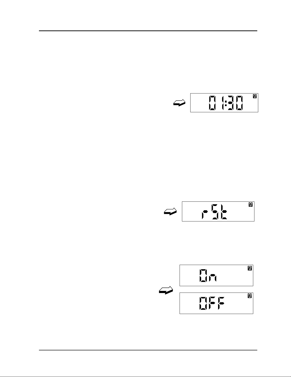
3.5.4 Starting/Stopping The Seconds Count Down Timer
To start/stop the seconds countdown timer, press and hold the
button until this top-level display
appears.
Two sub-displays are available (in the following sub-display order):
♦
♦
Page 30
Count-down Time MM:SS
Reset (rSt)
ISSUE 5
Thermo
ELECTRONIC PERSONAL DOSEMETER HANDBOOK
The count-down timer is a useful facility for activities where actions need to be
completed within known time periods. The User may start, stop and reset the
count down timer using the button. When the timer expires th e appropriate alarm
is sounded. The count down time period is pre-set and can only be adjusted via
the IR communications link.
Count-Down Time
Short-press the button to display the
‘Count-Down Time’ (which indicates the
count down time period, o r the remaining
count down time available).
Double-press the button to start the digits counting down to zero. The display is in
units of minutes and seconds. The maximum count down time available is 99
minutes, 59 seconds.
The count down function continues when t he display reverts to th e default display
after the display t imeout period. Ho wever it is usefu l to ‘lock on’ to this display as
described in section 3.4.
EPD/HB/40521/000
OPERATING INSTRUCTIONS
Stopping the Timer
To stop the timer double-press the button again. The d igits will stop decr ea sin g.
Reset
Short-press the button to select the
display shown opposite. Double press
the button and the display will flash.
Double-press the button again to confir m the reset (the display will show the reset
time at its reset value). The timer may now be star t ed as described above.
3.5.5 Turning the EPD off
To turn the unit off, press and hold the
button until the word ‘On’ appears:
Only one sub-display is available:
♦
On/Off
This function enables the EPD to be placed in sleep or OFF mode. In OFF mode
power consumption is reduced considerably and the EPD stops measuring
radiation.
Thermo
ISSUE 5
Page 31

EPD/HB/40521/ 000
ELECTRONIC PERSONAL DOSEMETER HANDBOOK
OPERATING INSTRUCTIONS
Assuming that the display shows On, double-press the button. The display will
change to “OFF” (flashing). Double- press the button again to confir m the request .
The display will change to the word “OFF” (not f lashing), conf irming that the unit is
in OFF mode and not measuring radiation.
To return to operating mode pre ss and hold the button. The display will rever t to
the default display.
Note
: ON/OFF control via the button may be inhibited by the appropriate setting
of the EPD internal configuration via the IR communications link.
3.5.6 Displaying Peaks (Rate High)
To display peaks (high rate),
press and hold the button until
this top-level display appears:
Two sub-displays are available (in the following sub-display order):
♦
Peak Hp(10)/h Dose Rate
♦ Peak Hp(0.07)/h Dose Rate
These displays show the highest dose rate t hat the EPD has measured since the
peaks were last cleared. The peak dose rates measured are recorded for
penetrating and superficial dose rates, together with the times at which these
rates occurred (to a resolution of 1 second).
Peak Hp(10)/h Dose Rate
Short-press the button to display the
Peak Hp(10)/h Dose Rate:
Peak Hp(0.07)/h Dose Rate
Short-press the button again to
display Peak Hp(0.07)/h Dose
Rate:
Note:
Peaks can only be cleared via the IR communications link.
3.5.7 EPD Confidence Test
ISSUE 5
Page 32
Thermo

ELECTRONIC PERSONAL DOSEMETER HANDBOOK
To perform the EPD confidence test, press and hold the button until this
top-level display appears:
Only one sub-display is available:
♦
Test
This test can be run at any tim e during oper ational use as a con fidence check that
the EPD is functioning correctly. Throughout the confidence test the heart-beat
(activity) indicator flashes onc e per second. The confidence test can be stopped
at any time by pressing the button.
Note: During the EPD confidence test a brief detector test is performed, during
which dose accumulation is momentarily inhibited (1 to 2 ms
approximately).
Double-press the button. The EPD will commence its confidence test routine, as
follows:
1. The all-segment display is displayed for approximately 5 seconds. This
allows the user to check that all segments ar e f un c tion al (se e Figu r e 3 .2).
EPD/HB/40521/000
OPERATING INSTRUCTIONS
2. The alarm will sound and the LED will flash for appro ximately 2 seconds.
This indicates that the sounder and LED are functional.
3. The all-segment display will disappear. The alarm will continue to sound
and the LED will continue to flash, at an increased rate, for ap proximately 6
seconds. This indicates that the LCD segments can be turned off, and that
the tone frequencies are fun c tion al.
4. The all-segme nt display will reappear for approximately 5 seconds and the
LED will slow flash.
5. The all-segment display will disappear and the default display will appear.
This indicates that the confidence test has been successfully completed
and that the EPD is ready for operational use.
Upon completion of the confidence test, the unit reverts to the default display. If
the confidence test is unsuccessfu l a le tter ‘F’ followed by th ree digit s is displayed .
Note the failure codes and refer to Section 5 (Failure Modes and Fault Diagnosis).
Thermo
ISSUE 5
Page 33

EPD/HB/40521/ 000
ELECTRONIC PERSONAL DOSEMETER HANDBOOK
OPERATING INSTRUCTIONS
3.5.8 Cleari ng Dose Displays
To clear dose displays, press
and hold the button until this toplevel display appears:
Only one sub-display is available
♦
This mode is used to clear the Hp(10) and Hp(0. 07) doses.
Note
Press the button once to select the
display shown opposite.
Double-press the button again and the display will flash. Double-press the button
again to confirm the req uest. The display will change to 0000 and return to the
default display. The Hp(10) and Hp( 0. 07 ) dose s have now been cleared.
Clr?
: The total doses are not cleared.
3.5.9 Displaying/Setting Dose Alarm Thresholds
To display and/or set dose
alarm thresholds, press and
hold the button until this
top-level display appears:
Three sub-displays are available (in the following sub-display or de r ) :
♦
♦ 2
♦
1st Hp(10) Dose Alarm
nd
Hp(10) Dose Alarm
Hp(0.07) Dose Alarm
The EPD can be used as a ‘personal alarming’ dosemeter, with alarm thresholds
for accumulated dose alarms. This mode displays the current settings for the
dose alarm thresholds. The alarm threshold can be modified by the user, if
required, but only when the default setting is set to ‘adjustable’. The user is
barred from modifying t he threshold if the default is set to ‘not adj ustable’. These
default settings can only be set via the IR communications link.
There are two Hp(10) alarm thresholds and a single Hp(0.07) alarm threshold that
can be displayed and modified. The 2
nd
Hp(10) dose alarm has the higher pr iority
ISSUE 5
Page 34
Thermo

ELECTRONIC PERSONAL DOSEMETER HANDBOOK
and should always be set to a higher value than the 1st Hp(10) alarm. The
accumulated dose alarm threshold s can be set using the button as follows:
st
1
& 2nd Hp(10), Hp(0.07): 10µSv, 50µSv, 100µSv, 500µSv, 1mSv, 5mSv,
10mSv, 50mSv, 100mSv, 500mSv, 1.0Sv.
EPD/HB/40521/000
OPERATING INSTRUCTIONS
Example of 1
st
Hp(10) Dose alarm
threshold display set at a default
value of 500
µ
Sv:
Other values for the dose alarm thresholds may be set via the IR communications
link.
Changing The Dose Alarm Thresholds
To change the 1
st
Hp(10) dose
alarm threshold select the display
above and double-press the
button. The display will change to
the following with the digits
flashing:
Alarm Set Limits: 10
µSv to 1Sv.
Pressing the button will increase the alarm threshold in the following steps: 10
µ
50
Sv, 100µSv, 500µSv, 1mSv, 5mSv, 10mSv, 50mSv, 100m Sv, 500mSv, 1. 0Sv.
When the required threshold is reached double-press the button to confirm the
value and the flashing display will stop.
If you start to change the threshold and change your mind this option can be
aborted, as follows:
Short-press the button until the
following is displayed (letters
flashing). Double-press the button
to confirm that you wish to escape
and return to the previous alarm
threshold.
If the “ESC” screen is displayed and the butt on is not pressed, after default timeout the display will return to the dose alarm threshold that was being set-up.
Again, if the button is not p r essed, the display will return to t h e default screen after
a further time-out period.
µSv,
Thermo
ISSUE 5
Page 35

EPD/HB/40521/ 000
ELECTRONIC PERSONAL DOSEMETER HANDBOOK
OPERATING INSTRUCTIONS
3.5.10 Displaying/Setting Dose Rate Alarm On/Off Thresholds
To display and/or set dose rate
alarm ON thresholds, press and
hold the button until this top-level
display appears:
Three sub-displays are available (in the following sub-display or de r ) :
♦ 1
st
Hp(10)/h Dose Rate Alarm ON
♦
♦
2nd Hp(10)/h Dose Rate Alarm ON
Hp(0.07)/h Dose Rate Alarm ON
To display and/or set dose rate
alarm OFF thresholds, press the
button until this display appears:
Three sub-displays are available:
♦
♦ 2
♦
1st Hp(10)/h Dose Rate Alarm OFF
nd
Hp(10)/h Dose Rate Alarm OFF
Hp(0.07)/h Dose Rate Alarm OFF
The EPD can perform the role of a ‘personal alarming’ EPD with a larm thresholds
for dose rate. There are two Hp(10)/h dose rate alarms and a single Hp(0.07)/h
dose rate alarm that can de displayed. The 2
higher priority and should always be set to a higher value than the 1
nd
Hp(10)/h dose alarm has the
st
Hp(10)/h
alarm. The alarm thresholds can be modified by the user, if required, but only
when the EPD default setting is set to ‘adjustable’. The user is barred from
modifying the thresholds if the EPD default is set to ‘not adjustable’. These
default settings can only be set via the IR communications link.
The dose rate alarm thresholds can be set using t he b ut t o n as f ollows:
10
µSv/h, 50µSv/h, 100µSv/h, 500µSv/h, 1mSv/h, 5mSv/h, 10mSv/h,
50mSv/h, 100mSv/h, 500mSv/h, 1.0Sv/h
Other values for the dose rate alarm thresholds may be set via the IR
communications link.
ISSUE 5
Page 36
Thermo

ELECTRONIC PERSONAL DOSEMETER HANDBOOK
OPERATING INSTRUCTIONS
Note: To avoid false alarms due to count ing statistics it is recommended that the
Hp(0.07)/h dose rate alarm is not set to less than 100
Example 1
alarm threshold display set at a
default value of 500
'On' and 'Off' alarm thresho lds allow hysteresis for dose rate alarms, see section
3.5.1. If hysteresis is not to be used the ‘O n’ and ‘Off’ thresholds should be set to
the same value.
Changing the Dose Rate Alarm Thresholds (ON and OFF)
To change the 1
rate on alarm threshold, for
example, select the above display
and double-press the button. The
display will change to the following
and the digits will flash:
Alarm Set Limits: 10
Pressing the button will increase the alarm threshold in the following steps:
10
µSv/h, 50µSv/h, 100µSv/h, 500µSv/h, 1mSv/h, 5mSv/h, 10mSv/h, 50mSv/h,
100mSv/h, 500mSv/h, 1.0 Sv/h. When the required threshold is reached doublepressing the button to confirm the value an d t he flashing display will stop.
st
Hp(10)/h dose rate on
µ
Sv/h:
st
H
(10)/h dose
p
EPD/HB/40521/000
µ
Sv/h
:
µ
Sv/h to 1Sv/h
Thermo
If you start to change the threshold and change your mind this option can be
aborted, as follows:
Short-press the button until the
following is displayed (letters
flashing). Double-press the button
to confirm that you wish to escape
and return to the previous alarm
threshold.
If the ‘ESC’ screen is displayed and the button is no t pressed, after default timeout the display will return t o dose alarm thres hold that was being set- up. Again, if
the button is not pressed, the display will return to the top level default screen
after a further time out period.
ISSUE 5
Page 37

EPD/HB/40521/ 000
ELECTRONIC PERSONAL DOSEMETER HANDBOOK
OPERATING INSTRUCTIONS
Notes
1. The ‘On’ threshold must always be greater than or equal to the ‘Off’
2. If an attempt is made to set the ‘On’ threshold below the ‘Off’ threshold the
3. If an attempt is made to set the ‘Off’ threshold above the ‘On’ threshold the
3.5.11 Setting The Sounder
To change the EPD sounder
settings, press and hold the
button until this top-level
display appears:
Three sub-displays are available (in the following sub-display or de r ) :
♦ Button Beep Enable/Disab le
:
threshold.
‘Off’ threshold will be set automatically to the same value as the ‘On’
threshold.
‘Off’ threshold will be set automatically to the same value as the ‘On’
threshold.
♦
♦
Note
Dose Chirp Adjustment
Internal Counters Display
: This option will not enable/disable the alarm sounder. Enabling/disabling
the sounder under alarm conditions can only be set via the IR
communications link (see Section 3.2.4).
Button Beep Enable/Disable
The EPD can be configured to beep every time the button is pressed. This
feature may be toggled 'on' and 'off ' via the button, or via the IR communications
link (i.e.
EasyEPD2
).
Note
: If the button beep has been disabled via the button any subsequent
initialisation of the EPD will revert the button beep to ON (enabled). If the button
beep has been disabled via the IR communications link, the button beep will
remain disabled regardless of any subsequent EPD initialisation.
Short-press the button to display
the button beep enable/disable
window. To configure the beep
feature 'off' or 'on' double- press the
button while the EPD is displaying
ISSUE 5
Page 38
Thermo

ELECTRONIC PERSONAL DOSEMETER HANDBOOK
the following displays. Button Beep Enabled
Button Beep Disabled
Dose Chirp Adjustment
The EPD can be configured to give a warning chirp at every preset increment in
Hp(10)/h, penetrating (d eep) dose. This increment can be set between 0.01
and 100
µSv, or disabled by setting the increment to 0.
Short-press the button to display
the current dose per chirp:
An increment set to
opposite. W
µ
Sv/chirp and a dose rate of 10mSv/h
1
ith a chirp sensitivity of
1µSv is shown
the sounder will average 2.8 chirps every
second.
To change the chirp rate, doublepress the button at current dose
chirp display. The display digits will
flash.
Dose Chirp Limits: 0.01
µSv to 100µSv.
Note: 0 = Off ( no chirp function ).
Pressing the button will increase the dose per chirp in the following increments:
µ
0.0
Sv, 0.01µSv, 0.05µSv, 0.1µSv, 0.5µSv, 1.0µSv, 5µSv, 10µSv, 50µSv,
µ
100
Sv. When the required sensitivity is reached “double-pressing” the button will
confirm the value and the flashing disp lay will stop.
EPD/HB/40521/000
OPERATING INSTRUCTIONS
µSv
Thermo
ISSUE 5
Page 39

EPD/HB/40521/ 000
ELECTRONIC PERSONAL DOSEMETER HANDBOOK
OPERATING INSTRUCTIONS
If you start to change th e sensitivity,
and change your mind, the option
can be aborted. Short-press the
button until the following is displayed
(letters flashing).
Double-press the button to confirm you want to return to the previous chirp
sensitivity. To switch off the dose chirp double- press the button when 0.0
displayed.
If the “ESC” screen is displayed and the button is not pressed, after default timeout the display will return to dose chirp adjustment display. Again, if t he button is
not pressed, the display will return to the top level default screen after a further
time out period.
Internal Counters Display
Short-press the button to display the
current internal counters display.
The display is in hexadecimal format and shows the last digit of: hard gamma
(HG), soft gamma (SG), full beta (FB) and beta compensation (BC) counts
respectively. This display is intended for test purposes and may be useful for
identification of faults or operational pro blems.
µ
Sv is
ISSUE 5
Page 40
Thermo

ELECTRONIC PERSONAL DOSEMETER HANDBOOK
SECTION 4
TECHNICAL DESCRIPTION
This section provides a technical description of the EPD and contains a summar y
of the EPD’s radiological features tog ether with a summ ar y of th e EPD’s elec tr ical,
mechanical and environmental characteristics.
4.1 General
The EPD is of rugged construction and is suitable for most conditions that can
reasonably be expected in industrial environments. The radiological features of
the EPD are summarised below (a full radiological specification is given in
Appendix A to this handbook):
♦
Sensitivity to X and γ radiation, β particles
EPD/HB/40521/000
TECHNICAL DESCRIPTION
♦
♦
♦ Direct readout of personal dose equivalents Hp(10)
♦ Neutron response <2%
♦
♦
♦ Resolution for dose display 1µSv (0.1mrem) at levels up to 10mSv (1 rem)
♦
♦
♦
Multiple PIN diode detectors
4 channel parametric algorithm processing
(penetrating/deep/whole body) and Hp(0.07) (superficial/shallow/skin )
Meets relevant parts of BS-EN-ISO61526 for dose equivalent monitors
(unless otherwise specified)
Dose display and storage 0µSv to >16Sv (0.0 mr em to > 1600 rem) auto
ranging
Resolution for dose storage 1/64µSv
Dose rate display 0µSv/h to >4Sv/h auto ranging, resolution 2 most
significant digits or 1µSv/h at lower levels (10
Dose rate peak store 0µSv/h to >4Sv/h resolution 1µSv/h
µ
Sv/h for Hp(0.07)/h)
Thermo
ISSUE 5
Page 41

EPD/HB/40521/ 000
ELECTRONIC PERSONAL DOSEMETER HANDBOOK
TECHNICAL DESCRIPTION
4.2 Electrical Description
4.2.1 Electrical Characteristics
Power Supply: One AA Lithium Thionyl Chloride (LTC) battery 3.6 V),
giving typically 5 months continuous operation at an
average dose rate <5
hours total during battery life.
or:
One standard AA Alkaline battery (1.5 V), giving typically
55 days continuous operation at an ave rage dose <5
with the alarm sounding <2 hours total during batt ery life.
Confidence Test: Activated on start-up and by the button when the
CONFIDENCE TEST mode is called-up (see Section
3.5.7).
µ
Sv/h with the alarm sounding <5
µ
Sv/h
Detector Test: Performed during the start-up sequence and as a
background test, and under demand via the IR interface .
Normal dose processing is inhibite d during detector test for
a period of 1 to 2 ms.
Battery Test: Configurable time interval between 1 to 60 minutes.
(15 minutes recommended).
Alarm sounder : 98 dB(A) to 101 dB(A) at 20 cm (4kHz loud mode)
80 dB(A) to 90 dB(A) at 20cm (4kHz quiet mode).
4.2.2 Battery Management
The EPD circuitry is designed to operate at 3.6V DC. The EPD can be powered
by either a 3.6V Lithium Thionyl Chloride (LTC) (Sulphurous Oxychloride, SOCL
battery or a standard 1.5V AA Alkaline type ba ttery.
The EPD software runs an internal battery condition test at regular intervals
(between 1 and 60 minutes). Th is time interval is factory preset to 15 minute s and
should not be adjusted except following consultation with Ther m o Ele ctron.
EPDs prior to software version 11:
)
2
If a 1.5V Alkaline battery is inst alled the EPD automatically switches-in a step- up
converter to maintain the 3.6V o perating voltage. The step-up converter is also
switched in as the LTC battery runs down. However, the EPD will not start up if it
ISSUE 5
Page 42
Thermo

ELECTRONIC PERSONAL DOSEMETER HANDBOOK
is fitted with a LTC battery that has been discharged sufficiently to require the
step-up converter to opera t e .
Operationally, as the voltage from either battery type falls, a series of preset
voltage thresholds operate as follows:
(i) The in ternal step-up converter is switched in to ma intain the voltage at the
EPD’s operating level.
(ii) As the battery voltage under load continues to fall, the low battery alarm
flag is activated to indicate when a minimum of 10 hours battery life is
remaining. Different thresholds are automatically selected for LTC or
alkaline batteries.
(iii) As the battery voltage under load finally falls below tolerance the EPD
resets (blank display). In some cases the EPD may reset repeatedly,
giving rise to a quiet ticking sound. The EPD battery must be rep lac ed.
EPDs from software version 11 onwards:
These EPDs have the step-up converter permanently activated to maintain the
required circuit operating voltage as either the Lithium or the Alkaline battery
voltage falls. The EPD makes the following information available over the IR
comms link:
•
Type of battery current ly fitted: Low volts (Alka line) or high v oltage (Lith ium
Thionyl Chloride)
•
The current battery voltage (measured at the last battery load test –
normally every 15 minutes)
•
The current regulated circuit voltage (measured within the last 14 seconds)
•
The battery voltage threshold at which the battery low warning is raised for
low voltage (Alkaline battery) *
•
The battery voltage threshold at which the battery low warning is raised for
high voltage (Lithium battery)*
* These thresholds should not nor mally require adjustment and any adjustment
considered should first be agreed with Ther mo Ele ctron.
The battery low alarm and LCD segment are activated when the battery voltage
falls below the appropriate battery low threshold. The EPD will continue to run
normally thereafter for a period of at least 10 hours, though this may be shortened
by continuous audible alarm outpu t. When the EPD is no longer able to contin ue
correct processing it enters a hardware reset state in which intermittent audible
alarms are output until such time as the battery nears complete discharge state.
This may continue for several minutes or longer. As the sound is initiated by the
hardware it cannot be muted by pressing the button, but only by removing the
battery.
EPD/HB/40521/000
TECHNICAL DESCRIPTION
Thermo
ISSUE 5
Page 43

EPD/HB/40521/ 000
ELECTRONIC PERSONAL DOSEMETER HANDBOOK
TECHNICAL DESCRIPTION
Additional information and warnings relating to the EPD battery are given in
Section 6.2.
4.2.3 On / Off Operating Modes
The EPD has an ON/OFF power saving facility, in which the detectors are turned
off, which is intended for short-term storage (e.g. overnight). In the power saving
mode the LCD will display OFF (i.e. the EPD is of f - see also Section 3.5.5). In
the EPD OFF condition battery drain is reduced to approximately 20% of the drain
when the EPD is in the ON co ndition (i.e. fully operational). The EPD does not
measure radiation when it is OFF.
Alternative OFF Display
EPDs of software version 11 and later may be configured to display a 4 digit
Hexadecimal value instead of the OFF display. The 4 digit hex value may be
written using suitable software, e.g. EasyEPD2. This facility is to provide
customers with the option of having the EPD display the Calibration due date
when the EPD is Off. So for example, 2512 could mean calibrate on 25
December.
th
ISSUE 5
Page 44
Thermo

ELECTRONIC PERSONAL DOSEMETER HANDBOOK
4.3 Mechanical Description
4.3.1 Mechanical Characteristics And Dimensions
Display and function control: Single button on the front of the EPD (recessed
to prevent inadvertent operation).
Case material : High impact Polycarbonate/ABS blend.
Clip : High impact plastic clip assembly comprising:
♦
spring clip
♦ lanyard plate,
Weight : 95 gm including LTC battery and clip.
88 gm with lanyard plate only (clip removed).
Dimensions : See Figure 4.1.
EPD/HB/40521/000
TECHNICAL DESCRIPTION
4.3.2 Brief Mechanical Desc ri pt ion
The EPD is of semi-modular construction and compr ises an inner co nduct ive liner,
an outer case assembly and lid. The inner liner houses the EPD’s electronic
components. The outer case, consisting of a moulded front and back, fits around
the inner liner and is fused to gether to provide physical protection. The lid, which
is fitted to the top of the outer case, has a tight tolerance and is locked in place as
an integral part of the EPD assemb ly. The outer case an d lid are designed not
come apart.
The complete assembly is engineered to house functional and operation
components (e.g. EPD battery, LCD displa y, button, alarm LED, alarm sounder,
IR communications link and beta window (see Fig ure 2.1). Externally, the outer
case is contoured to receive, and lock in place, a clip assembly ( see Section 6. 3).
Essentially, component replacement is limited to t he EPD bat tery, bat tery cap and
clip assembly.
to
Thermo
ISSUE 5
Page 45

EPD/HB/40521/ 000
TECHNICAL DESCRIPTION
ELECTRONIC PERSONAL DOSEMETER HANDBOOK
Figure 4.1 - EPD Dimensions
ISSUE 5
Page 46
Thermo

ELECTRONIC PERSONAL DOSEMETER HANDBOOK
4.4 Environmental Description
4.4.1 Environmental Characteristics
Operating Temperature : -10°C to +40°C.
Storage: -25°C to +70°C.
Humidity: 20% to 90% RH non condensing.
Protection: IP55. Total protection against dust and against low
pressure jets of water from all directions.
Vibration: IEC 1526 2g, 15 min, 10 - 33 Hz
Shock: 1.5 m drop on each surface onto concrete.
EMI/EMC: Exceeds MIL STD 461D RS103 (see Appendix B).
EPD/HB/40521/000
TECHNICAL DESCRIPTION
4.4.2 Brief Environm ent al De scription
The EPD is designed for use in the following environments:
♦ Office and Laboratory environme nt ,
♦
♦
♦
Industrial environments,
Hospitals
Military environments (including dockyards and shipping - but excluding
exposure to salt water and extremes in military en vir o nment).
Thermo
ISSUE 5
Page 47

EPD/HB/40521/ 000
TECHNICAL DESCRIPTION
4.5 Infra-red Interface
The EPD contains an infra-red interface (see Figure 4.2) which can optically
communicate (read and write) to PC-based hardware using a suitable infra-red
communications program. This interface is compatible with IrDA level 1 protocol.
ELECTRONIC PERSONAL DOSEMETER HANDBOOK
Figure 4.2 - EPD Infra-Red Interface
4.5.1 Communicating With The EPD
The EPD electronically stores dose and dose rate data, together with other
information that is required to control and configure the EPD. Communication with
the EPD is essential in order to rea d data from store an d to write data to store so
that EPD parameters, operat io nal c ontrol and general functionality can be set .
During the read/write process the EPD can be configured for any (or all) of the
display selections shown in Figure 3.4 to be made available to the user, as
required. Only limited functions can be configured via the EPD but ton.
On the front of the EPD there is an IR communications link for reading and writing
data. Communication with the EPD is usually via an IR adapter, which is
connected to a host PC.
EasyEPD2
maintaining, configurin g and readin g EPDs. Th e IR communication r ange is up to
1m, over an angle of ±30° from the normal to the front of the EPD.
After any successful communication via the IR communications link the EPD will
show the default display. There is a time-o ut from the last communication after
which the EPD reverts to normal display. There is also an inhibit timer that
prevents an EPD from re-establishing communications immediately after
is a Thermo PC-based software product for
ISSUE 5
Page 48
Thermo

ELECTRONIC PERSONAL DOSEMETER HANDBOOK
TECHNICAL DESCRIPTION
communications are completed. This gives the user time to remove t he EPD from
the IR field. The EPD continues to measure radiation during commu nic ation.
4.5.2 EPD Configuration via the IR Communications Links
Communication via the EPD’s IR communications link will allow access to the
following EPD functions and displays:
♦ Default Display
EPD/HB/40521/000
♦
♦
User Identification
Dose and Dose Rate
♦ Alarms and Alarm Thresholds
♦
Counts
♦ Dose Quality
♦
♦
♦
♦
Control of the EPD
Status
Scratch Pad
Timed Events
♦ Dose Profile
♦
♦
♦
Special Total Dose Store
ADS Issue
Calibration Parameters
Access to these configuration parameters is restricted as follows:
1) CALIBRATION FACTORS:
Write access to calibration parameters is pre ven te d un le ss th e EPD is
configured by the manufacturer with calibr ation parameters unlocked (default is
locked). If the calibration parameters are un lo cked the n suit able s/ w ava ilable
through Thermo can adjust the ‘gains ’ of the EPD calibration within specified %
limits from the original manufacturer’s calibration.
Thermo
ISSUE 5
Page 49

EPD/HB/40521/ 000
ELECTRONIC PERSONAL DOSEMETER HANDBOOK
TECHNICAL DESCRIPTION
2) PTB APPROVED EPD
The Physikalisch-Technische Bundesanstalt (PTB), Braunschweig and Berlin,
is the national institute of natural and engineering sciences and the highest
technical authority for met rology and phys ical safety engineering of the Federal
Republic of Germany.
EPDs supplied to Germany and elsewhere under PTB approval are specially
configured by the manufacturer to en sur e cer tain functions cannot be enabled,
as follows:
Alarm Configuration
Alarms cannot be configured Off, be disabled, set to quiet or low frequency.
This ensures that Alarm sound le vel is >85dB(A) at 30cm from the EPD. The
alarm times cannot be set to less than 10 minutes.
The following Alarm Control set tings may also not be changed f rom the factor y
configuration: Battery alarm level 1, Battery Alarm Level 2, Battery Type
Discriminator, Regulated voltage a lar m level.
LCD, Decimal Point position and display units.
PTB EPDs are configured such that the settings for de cimal places, dos e units,
off display, wearer display, overr ange fl ashing, an d 1 minute lo gging, cannot be
changed.
EPDs are factory configur ed to the required Display Settings and then 'locked'
in that condition. This configuration is required for PTB approved EPDs.
Calibration Factors
Beta/Gamma EPDs are supplied with calibration fa ct or s locked.
Any attempt to configure PTB Approved EPDs contrary to this specification will
fail. If the configuration is attempted using EasyEPD2 then EasyEPD2 will
display gives the error message 2 28.
ISSUE 5
Page 50
Thermo

ELECTRONIC PERSONAL DOSEMETER HANDBOOK
4.6 EPD Internal Processing & Facilities
This section describes the internal processing performed by the EPD and
the facilities provided over the IR communications link.
4.6.1 Memory Characteristics:
Memory Retention: 10-year data retention.
Dose Profile History: Settable interval from two seconds to 35
hours. Stores transitions of Hp(10) and
Hp(0.07) at a resolution of 1
to 579 records for transitions up to 127
less.
Dose Store (short term): Hp(10) and Hp(0.07). Can be reset after
each controlled area entry, day, month (etc)
by health physics staff or dose management
system, according to local procedures.
EPD/HB/40521/000
TECHNICAL DESCRIPTION
µSv. Store for up
µ
Sv or
Total Dose Store: Separate total dose store.
Special Total Dose Store: 12 entries, e.g. for automatic recording of end
of month dose etc.
Event Log: 23 entries for time recording of alarms etc.,
for incident assessments.
ADS Dose Store: Approved Dosimetry Service (Record of
Dose) dose memory area with password
protection.
Peak Dose Rates: Peak dose rates with time of occurrence.
Storage Times: 1 second resolution.
Alarm Flags: Various alarm and fault flags.
Timer: Count-down timer configurable up to 1 hour
39 minutes and 59 seconds (1 second
resolution).
Return for Read: Programmable warning.
Thermo
ISSUE 5
Page 51

EPD/HB/40521/ 000
ELECTRONIC PERSONAL DOSEMETER HANDBOOK
TECHNICAL DESCRIPTION
4.6.2 Alarm Characteristics:
Alarms: 2 each Hp(10) dose and dose rate alarms
1 each Hp(0.07) dose and dose rate alarms
Dose and Dose Rate Alarms: 0µSv to 16Sv and 0µSv /h to 16µSv/h
Recommended minimum settings to avoid
Alarm Types: Audible and visual alarms for dose, dose
Tones: High/low tones, loud/quiet volume in seven
resolution V 1/64µSv and 1µSv/h
false alarm 7µSv/h Hp(10)/h and 100µSv/h
Hp(0.07)/h
rate, count-down timer, read time and failure
mode. Alarms are configurable via the IR
communications link.
combinations of continuous or fast/slow
intermittent.
Hp(10) Dose Chirp: Settable from 0.01
4.6.3 Default Display
The default display is initially factory preset to read Hp (10) (the penetrating or
deep dose), or to an alternative default display as specified by the customer.
User-selected displays have a time-out period, wh ich can be set between 10 to 99
seconds. This time-out is the period of time that any display select ed by the user
will stay active before reverting to the default display. The time-out period may be
adjusted via the IR communications link. The default display can be changed to
any of the displays shown in Figure 3.4, again, via the IR communications link.
4.6.4 User Identification
The EPD retains details relating to the current user and the number of times tha t
the EPD has been issued. Wearer details comprise the user’s identification
number (i.e. the User ID) and the User Name The User Name can be a string of
up to 22 characters. By convention, an un-is sued EPD User ID is set to all ‘F’s
(FFFFFFFFFFFF). Typically, a User ID will have fewer than 12 digits, but it must
be an integer between 1 and 999999999999. A full description of User IDs is
given in Sections 3.5.1 and 3.5.2 .
User identification can only be set via the IR commun ications link.
µ
Sv/chirp.
µSv/chirp to 100
ISSUE 5
Page 52
Thermo

ELECTRONIC PERSONAL DOSEMETER HANDBOOK
4.6.5 Dose and Dose Rate
EPD/HB/40521/000
TECHNICAL DESCRIPTION
The EPD calculates dose and d ose rate. Dose is ac cumulated in 3 stores:
Total Dose
and
Dose
The EPD displays Hp(10) (penet rating or deep) dose and Hp(0.07) ( superficial or
shallow) dose.
associated with the issue of an EPD. It is this value that is compared with dose
alarm thresholds and an alarm raised if the value exceeds the thresholds. The
EPD records
is displayed as a decimal equivalent. Total Do se is a store providing a long-term
record of dose accumulated by the EPD.
range between 1
Accumulated dose is written to non-volatile memory at least every 15 minutes.
Therefore is a reset occurs, due to the battery cap being removed or the EPD
being heavily dropped, or a passivated battery fitted, up to 15 minutes of
accumulated dose may be lost. Such events howe ver ar e detect ed and a count of
resets provided as quality data associat ed with t he accumula ted do se, see se ction
4.6.7.
Note that from software version 11 EPDs it is possible to configure the EPD to
make additional logs to the non-volatile memory at 1 minute intervals if the dose
received in the preceding minute exceeds 1 uSv.
Display characteristics that can be set are:
Units Sv or rem
ADS Dose
Dose
is regarded as a short-term record of dose received, usually
Dose, Total Dose
µ
Sv to 16Sv (maximum resolution 1µSv).
. Dose rate is the current rate calculated by the EPD.
ADS Dose
and
in units of 1/64µSv, although this
The LCD display can be set to auto-
Dose
,
Decimal Places: 2 or 3 decimal places
Resolution:
Default Time: 10 to 99 seconds
Note: For Gamma dose, two counts are appr oximately equivalent to 1/64
for Beta dose one count is approximately 1/6
inaccuracies doses should only be displayed in micro sieverts (or 0.1 rem),
but when summing a number of d oses the full resolut ion should be used to
minimize rounding errors.
Dose Rate
This is the current dose rate as calculated by th e EPD. It may be viewed on the
display or read via the IR communications link. Dose rates are calculated using
an averaging algorithm to re duce statistical variations to within ±20% under mo st
conditions. This results in increased averagin g time constants at low dose rates.
Thermo
Page 53
µ
Sv or mSv
ISSUE 5
µ
Sv and
µ
Sv. To avoid statistical

EPD/HB/40521/ 000
TECHNICAL DESCRIPTION
Averaging time constants used to calculate penetrating dose rate Hp(10)/h
maximise at 60 seconds below 70uSv/h and therefore the statistical errors
increase as the dose rate drops below 70uSv/h. Additional processing is us ed to
provide faster response but with reduced accuracy when rapid changes in dose
rate are observed. The algorithm is a compromise that reduces statistical errors
but gives a fast response t ime. The dose rate displays on the LCD are limited to 2
significant digits.
Longer time constants have to be used when a veraging the beta dose due to the
lower sensitivity of the beta detectors. The time co nstant used maximises at 100
seconds below 1mSv/h. Due to limitations in the processing and memory
available, this time constant cannot be reduced when rapid changes are
observed, and the Hp(0.07 )/h dose rate is approximated as the sum of Hp(10)/h
and the beta dose rate. This approximation means that at low gamma energies
(below 50 keV) the Hp(0.07)/h dose rate
comparison to the Hp(0.07) dose response. However, above 25 keV the dose
rate
response remains within ±30% accuracy criteria.
Peak Dose Rate
The highest dose rate calculated by th e EPD since this value was last cleared is
termed the peak dose r ate. The peak dose rates and t he times at which these
peak rates occur are recorded and can be displayed on the LCD or read over the
IR communications link.
Note
: Peak dose rate times are stored to 1 second resolution.
ELECTRONIC PERSONAL DOSEMETER HANDBOOK
typically under-responds by up to 25% in
4.6.6 Counts
The EPD has four internal counters:
♦
♦
HG: Hard Gamma
SG: Soft Gamma
♦ FB: Full Beta
♦
BC: Beta Compensating
These record the pulses output by each of the radiation de te cto r s .
The EPD calculates the Hp(10) and Hp(0.0 7) doses by weighted summing (ratios
set during calibration) of the count s r ece ive d on t h e fo ur de t ector channels.
Counts can only be read via the IR communications link, although the least
significant digits are visible on the interna l cou nt s displa y ( sect io n 3.5 ).
ISSUE 5
Page 54
Thermo

ELECTRONIC PERSONAL DOSEMETER HANDBOOK
4.6.7 Dose Quality Flags
There are 7 dose quality flags set within t he EPD. Dose quality can only be read
and cleared via the IR communications link. They are normally cleared with the
dose and detector counters at the start of an Issue period, e. g. by Access Control
or Issue/Return software. In ‘dose of record’ systems, EPD dose, detector
counters and quality factors are all read together and stored on the system
database to allow later integrity c hecking of the dose recorded. The dose qu ality
flags are as follows:
(i) Reset Count
The reset count is a count of the n umber of times the unit has been reset, eithe r
by:
(a) removing and re-fitting the bat tery, or battery cap,
(b) use of an unsuitable or passivated Lithium battery,
(c) b y a commanded reset via the IR communications link,
(d) by a software reset,
(e) by a f au lt condition.
Note that the EPD loses recent dose received since the last log of dose to non-
volatile memory, as described in section 4.6.5.
EPD/HB/40521/000
TECHNICAL DESCRIPTION
(ii) Knock Time Seconds
The EPD detectors are susceptible to large mechanical shocks. This is overcome
by detecting the shock with a piezo ‘knock’ detector. The EPD continues to
accumulate dose during the shock period, but at the dose rate that was present
immediately before the knock was detected. However, if the dose rate is greater
than approximately 4mSv/h the cou nts caused by the knock will be small relative
to the radiation count s a nd t her efor e a ll count s are used in the calculat io n of dose .
Knock Time is the time period over which knock processing has taken place.
Continuous Knock detection for greater than 15 seconds will cause an abuse
alarm (see
Abuse Warning
(iii) Dose Over-range
The dose over-range flag indicates that one of the dose stores has exceeded 1Sv
(100 rem) . Dose continues to accumulate above this value to a maximum of
16.777215 Sv (1677.7215 rem).
Thermo
Page 55
).
ISSUE 5

EPD/HB/40521/ 000
ELECTRONIC PERSONAL DOSEMETER HANDBOOK
TECHNICAL DESCRIPTION
(iv) Dose Rate Over-range
The dose rate over-range flag indicates that the dose rate has exceeded 1Sv/h
(100 rem/h) at some time in the past, (i.e. the recorded dose may be inaccurate,
probably low, due to non-linearity at high dose rates).
(v) Counter Over-range
The counter over-range flag indicates that at least one detector has exceeded the
maximum count rate expected (300,000 counts/second - gamma counters and
26,000 counts/second - beta counters). A possible cause for this flag to set is that
the unit has either been exposed to some kind of extreme interference or has
developed a fault.
(vi) Abuse Warning
The abuse warning indicates that an abuse a larm has been activated. An abuse
alarm is activated if mechanical knocks are detected continuously for greater than
15 seconds (see
Knock Time Seconds
)
(vii) CRC Failure
The CRC failure flag is set as a result of an integrity check on a set of data
indicating that the EPD detected a checksum error in the dose data. Checksum
failures are corrected by retrieving the last stored dose from secure store
(EEPROM). During the correction process up to 15 minutes of dose may be lost.
(viii) Low Voltage (EPD software version 11 and later)
The EPD analogue circuitry detected a low supply voltag e con dition .
(ix) Detector Fault (EPD software version 11 and later)
The EPD ‘flash LED’ detector test fail ed.
4.6.8 Dose And Dose Rate Alarm Processing
The EPD performs alarm processing as described in this section. The occurrence
of a dose or dose-rate alarm is recorded by the following internal flags. These
flags make it easy for applications s/w to determine over the IR communications
link whether an alarm has occurred during an issue period. The flags are
therefore normally cleared over the I R communication s link at the start of an issue
period:
ISSUE 5
Page 56
Thermo

ELECTRONIC PERSONAL DOSEMETER HANDBOOK
EPD/HB/40521/000
TECHNICAL DESCRIPTION
♦
Three Dose alarm flags indicate that a dose has exceeded the
corresponding dose alarm thresholds. There are 1
st
and 2nd dose alarms
for Hp(10) and a single dose alarm for Hp(0.07).
♦
Three Dose rate alarm flags indicate that a dose rate has exceeded the
dose rate alarm thresholds. There are 1
st
and 2nd dose rate alarms for
Hp(10)/h and a single dose rate alarm for Hp(0.07)/h. The dose-rate flags
are not cleared automatically when the dose-rate falls below the reset
threshold.
nd
The 2
st
1
and the 2
alarm threshold (dose or dose rate) always has a higher priority than the
alarm threshold. The 1st alarm threshold can be considered as a warning value
nd
alarm threshold as a crit ical value. Therefore , the 2nd alarm threshold
should always be set to the higher value.
Dose rate alarms can be configur ed to wor k with hyst eresis. That is, the Hp (10)/h
1st and 2nd dose alarms and the Hp(0.07)/h dose rate alarm are each provided
with separate ON and OFF thresholds. When the dose rate equals or exceeds
the alarm ON threshold t he EPD will set an alarm flag and the sounde r will sound
and the LED flash (if enabled). The alarm is self-cancelling when the dose rate
falls below the alarm OFF threshold, but the alarm flag remains set.
Alarm thresholds are set via the IR communications link, or by the button if the
user is granted authority (see Figur e 3.4), to any value in the following ranges:
st
1
Hp(0.07)/h
1
Hp(0.07)
nd
& 2
st
& 2nd Hp(10)
Hp(10)/h
µ
0
Sv/h to 16.777215 Sv/h
0
µSv/h to 16.777215 Sv/h
µ
1
Sv to 16.777215 Sv
1
µSv to 16.777215 Sv
It is not recommended to set dose rate alarms to less than 7uSv/h (Hp10)/h or
µ
100
Sv/h Hp(0.07)/h as the statistical errors on the dose rate reading at these
levels will be greater than ±50%, and false alarms may occur in normal
background radiation conditions.
4.6.9 EPD Operating Status
The EPD retains information regarding its status. EPD status can only be read via
the IR communications link. Status information provided is:
♦
♦
♦
EPD Run Times
EPD State
Alarms
♦ Warnings
♦
Faults
♦ Event history
Thermo
Page 57
ISSUE 5

EPD/HB/40521/ 000
ELECTRONIC PERSONAL DOSEMETER HANDBOOK
TECHNICAL DESCRIPTION
EPD ‘Run’ and Off times
The EPD contains an accurate clock (±30 ppm) and records the elapsed time,
both for operating (Run Time) and in ‘OFF’ Mode. Times are recorded to a
resolution of 1 second. The OFF time is the number of seconds that the detectors
have been switched off (while the power has been present) .
Note
: When power is removed, or a reset occurs, the EPD clock reverts to a
value of up to 15 minutes prior to its value on power loss or reset.
EPD State
The EPD retains a record of the following information:
1.
2.
3.
Issue Count. This is the number of times the EPD has been issued.
Issued
. This is the present state of the issued flag, either EPD
Detectors State. This is the current state of the EPD’s operating mode,
Issued or EPD Not Issued.
i.e. ON or OFF.
Alarms
The EPD retains a record defining which of the following alarms has occurred.
The record is normally cleared by system software at the start of an issue period:
1.
2.
3.
3 Dose Alarm Flags
3 Dose Rate Alarm Flags
Return For Read. The EPD clock has exceed the Return For
Faults
The EPD retains a record of the following faults flags:
1.
2.
3.
Event Logged
Connection Failed. Communication with the EPD failed.
Cal Factors Bad
As section 4.6.8
. As section 4.6.8
Read time.
. An event (possibly but not necessarily a fault)
has been logged in the EPD’s event store.
. The EPD calibration factors failed a CRC
check and cannot be recovered from secure
store.
4.
EEPROM Fail. An un-recoverable EPD secure store failure
occurred.
ISSUE 5
Page 58
Thermo

ELECTRONIC PERSONAL DOSEMETER HANDBOOK
5. Bad Sectors. The number of bad EPD secure store sectors.
There is a maximum of nine spare sectors.
EPD/HB/40521/000
TECHNICAL DESCRIPTION
6.
7.
8.
9.
10
Detector Test Fail
. The EPD detector test was run and the
number of counts received were less than
required to pass the test.
Detector Threshold Fail
. The EPD detector thresholds failed to load
successfully
Radio Fail. Reserved for future use.
Other Fault
Disabled
. A fault occurred causing the EPD to reset.
. The EPD is not calculating dose.
Thermo
ISSUE 5
Page 59

EPD/HB/40521/ 000
TECHNICAL DESCRIPTION
4.6.10 Dose Profile
The EPD stores Hp(10) and Hp(0.07) dose to a resolution of 1µSv in non-volatile
store so that a profile of the dose over time can be recreated. The interval
between stores is set-up via the IR communications link.
Both Hp(10) and Hp(0.07) dose information is stored as a dose profile, the
minimum interval between entries in the dose profile is adjustable between 2
seconds to 35 hours, in 2 second intervals. The store holds up to 579 records for
transitions up to 127
Note:
A dose profile interval of zero seconds turn s off the dose profile function.
Dose profile can only be read via the IR communications link. Dose prof ile may
be synchronised to a particular time in the future, e.g. hourly logging on the hour.
Note
: The EPD has no conce pt of real-time but maintains a one-second tick that
is valid as long as the EPD is powered and not reset.
µ
Sv or less.
ELECTRONIC PERSONAL DOSEMETER HANDBOOK
ISSUE 5
Page 60
Thermo

ELECTRONIC PERSONAL DOSEMETER HANDBOOK
4.6.11 Event History Store
The EPD logs up to 23 events in non-volat ile store, together with a time stamp.
These comprise alarm and fault events see tables 4.1 and 5.2. From software
version 11, EPD ON and OFF events are also recorded ( s e e Table 4. 1) .
Note: The Event History time store wraps round after 194 days of operation.
After this time previous event- associated day/date(s) cannot be considered
as accurate. In addition elapsed time during loss of power is not re cor d ed.
Events On Events Off
Code
Text as displayed by
EasyEPD2
200 Failure Alarm on 220 Clear Faults
201 Over Range Alarm on 221 Over Range Alarm off
202 Hp10 Dose Alarm 2 on 222 Hp10 Dose Alarm 2 off
203 Hp07 Dose Alarm on 223 Hp07 Dose Alarm off
204 Hp10 Dose Alarm 1 on 224 Hp10 Dose Alarm 1 off
205 Hp10 Rate Alarm 2 on 225 Hp10 Rate Alarm 2 off
206 Hp07 Rate Alarm on 226 Hp07 Rate Alarm off
207 Hp10 Rate Alarm 1 on 227 Hp10 Rate Alarm 1 off
208 Battery Alarm on 228 Battery Alarm off
209 Return for read Alarm on 229 Return for read Alarm off
210 Count Down Alarm on 230 Count Down Alarm off
211 Abuse Alarm on 231 Abuse Alarm off
219 Detectors ON* 239 Detectors OFF*
* Version 11 and later software only
Code Text as displayed by
EasyEPD2
EPD/HB/40521/000
TECHNICAL DESCRIPTION
Other Events
Thermo
Code Text as displayed by
EasyEPD2
240 Power Converter Switched
On
241 Power Up Cold Start
242 Power Up Warm Start
Table 4.1 ( 3 parts ) EPD Events logged to the Event History Stor e .
ISSUE 5
Page 61

EPD/HB/40521/ 000
TECHNICAL DESCRIPTION
ELECTRONIC PERSONAL DOSEMETER HANDBOOK
This page intentionally blank
ISSUE 5
Page 62
Thermo

ELECTRONIC PERSONAL DOSEMETER HANDBOOK
FAULTS AND RECOVERY ACTIONS
SECTION 5
EPD FAULTS and RECOVERY ACTIONS
5.1 Overview
This section identifies the fault conditions that can occur and describes the
recovery procedure (if any) to be t ake n to r est or e t he EPD t o op er a t ion al u se.
The section is organised as follows:
1. Fault indication via sounder, alarm Led, LCD.
2. Internal logging of fault conditions.
3. Blank display and other “uncontrolled” faults.
4. Communications Error over the IR link.
5. LCD Display error codes.
6. Recovery Procedures.
EPD/HB/40521/000
Thermo
ISSUE 5
Page 63

EPD/HB/40521/ 000
ELECTRONIC PERSONAL DOSEMETER HANDBOOK
FAULTS AND RECOVERY ACTIONS
5.2 Visual and Audible Fault Indication
An EPD failure is usually indicated by a visual and audible alarm. In most
instances the EPD will display an erro r code on the LCD and the LED will flash.
The default audible alarm is as follows:
Alarm rate:
If alarm mute is enabled for the fault alar m the sounder can be silenced and the
alarm Led extinguished by the action of pr essing and holding the button. The fault
alarm can also be set to self mute after a timeout period in order to preserve
battery life. If this happens the unit will give a short sound every 30 seconds
thereafter.
An EPD conveys faults to the user by a number of displays, e.g.:
♦ Initialisation Error (
♦ Communications Error (
♦
Error Code ( Fxxx on the LCD )
♦
Blank Display
♦
Other faults (e.g. display lock-up, n o hea r tbeat etc.)
___ ___ ___ ___
――――
on the LCD )
≡≡≡≡
on the LCD )
slow intermittent rate
ISSUE 5
Page 64
Thermo

ELECTRONIC PERSONAL DOSEMETER HANDBOOK
FAULTS AND RECOVERY ACTIONS
5.3 Internal Logging of Fault Conditions
5.3.1 EPD Status Faults Record
The EPD logs data to an internal data record in EEPROM, to indicate that faults
have occurred. These faults are as follows:
1.
Event Logged. An event (dose alarm or a fault) has been logged
in the EPD’s event history store.
EPD/HB/40521/000
2.
3.
4.
5.
6.
7.
8.
9.
10.
Communication Error
. Communication with the EPD failed, typically the
unit was removed from the IR media
prematurely.
Cal Factors Bad
. The EPD calibration factors failed a CRC check
and cannot be recovered from secure store.
EEPROM Fail. An un-recoverable EPD secure store failure
occurred.
Bad Sectors
. The number of bad EPD secure store sectors.
There is a maximum of nine spare sectors.
Detector Test Fail. The EPD detector test was r un and the number
of counts received were less than required to
pass the test.
Detector Threshold Fail. The EPD detector thresholds failed to load
successfully
Radio Fail
Other Fault
. Reserved for future use.
. A fault occurred causing the EPD to reset.
Disabled. The EPD is ‘Off’ ( not calculatin g do se) .
This data may be read and cleared via the IR communications link & EasyEPD2.
5.3.2 Event Hi story store
The EPD logs up to 23 events in a non-volatile store, toget her with a time stamp.
The Event History store is accessible when the EPD is interrogated over the IR
communications link (e.g. by
see Tables 4.1 and 5.2.
The store comprises a circular ‘buffer’, the latest event over-writing the oldest.
Thermo
Page 65
EasyEPD2)
ISSUE 5
. Alarm and fault events are recorded,

EPD/HB/40521/ 000
ELECTRONIC PERSONAL DOSEMETER HANDBOOK
FAULTS AND RECOVERY ACTIONS
Note
: The date/t ime data field wraps roun d after 194 days of operat ion. After this
time previous event-associated day/date(s) cannot be considered as
accurate. In addition elapsed time du r ing loss of power is not recorded.
5.3.3 Dose Quality Factors
A number of faults and events are coun te d an d r ecorded in association
with the measured dose. They are zeroed when the dose is zeroe d an d
are subsequently read with the dose. These ar e r eferred to as the dose
quality factors and are described in section 4.6.7. Non-zero dose quality
factors imply that there may be an error in the dose reading due t o the way
the product has been used, rather than due to a fault within the unit. For
example, the battery cap may have been used or a passivated battery
fitted, causing a reset and potentially lost dose.
ISSUE 5
Page 66
Thermo

ELECTRONIC PERSONAL DOSEMETER HANDBOOK
♦
♦
♦
♦
♦
♦
♦
♦
♦
♦
♦
♦
♦
♦
♦
♦
FAULTS AND RECOVERY ACTIONS
5.4 Blank LCD Display and Other Faults
It may also be possible for the EPD to fail wit hout producin g or displaying an error
code, or causing an alarm, for example due to failure of the micro-controller or
digital circuit. A list of such fa ults and the r ecommended course of action is given
in the table below.
Symptom
Blank Screen
Nothing displayed on the
LCD, not even ‘Heart
Beat’ indication
Nothing displayed after
battery is inserted/
replaced.
Static Screen
‘Heart Beat’ indication
not flashing
Faulty Button
Cannot mute alarm
using button
No response to button
Faulty Sounder
No audible alarm during
Confidence Test
Sound fails to operate in
alarm condition
Likely Cause
Battery Failure
Battery cap not
corrected seated
or battery out of
specification
1 second timer error
Muting Disabled
Hardware fault
Hardware fault
Sounder Disabled
Recommended Action
Attempt to communicate with the
EPD/HB/40521/000
EPD via the IR communications link
to prove diagnosis.
Remove old and Insert new battery
and restart unit- see section 2.1. 2.
Communicate with the EPD via the
IR communications link to access
stored data.
Remove and replace battery cap
(see Section 2.1.2).
Use a recommended battery.
Attempt to communicate with the
EPD via the IR communications
link.
Replace battery and restart un itsee section 2.1.2.
Communicate with the EPD via the
IR communications link to access
stored data.
If there is still no ‘Heart Beat’
contact supplier.
Communicate with EPD via the IR
communications link.
Clear alarm conditions.
Enable muting if required.
Communicate with the EPD via the
IR communications link to access
stored data.
Contact supplier.
Contact supplier.
Enable sounder if required
Thermo
ISSUE 5
Page 67

EPD/HB/40521/ 000
♦
♦
♦
♦
ELECTRONIC PERSONAL DOSEMETER HANDBOOK
FAULTS AND RECOVERY ACTIONS
Faulty LED
No visual alarm during
Confidence Test
LED fails to operate in
alarm condition
Faulty Display
Missing or additional
segments on LCD
display
Hardware fault
LED Disabled
Contact supplier.
Enable LED if required
Hardware fault
Conf ir m fault by running a
CONFIDENCE TEST
Contact supplier.
Table 5.1 - Blank LCD & other faults
ISSUE 5
Page 68
Thermo

ELECTRONIC PERSONAL DOSEMETER HANDBOOK
FAULTS AND RECOVERY ACTIONS
5.5 Initialisation Error ( LCD - - - - )
A series of single dashes appearing on the LCD display indicates an initialisation
error following a reset or battery change:
EPD/HB/40521/000
Initialisation errors typically refer to corruptions to data in the EPD’s non volatile
memory (EEPROM). These are fa ults the user cannot usually repair. Follow the
procedures defined in section 8 to extract data and to recover normal operation
where possible.
5.6 Communications Error ( LCD
A series of triple dashes appearing on the LCD display indicates a
communications error:
≡≡≡≡
)
Thermo
This condition usually occurs when a data write operation fails to complete. The
typical cause is that the EPD unit is removed from the IR field before a critical
write operation has completed, for exa m ple an I ssu e of th e EPD to a per so n.
The error ( which is accompanied by an audible alarm ) alerts the user that the
EPD is not in a valid operatio nal sta te. Howev er as de scribed ab ove, the cause is
a user / operational problem and not a fault in the EPD.
An EPD will only raise this condition if it is first triggered by the system software,
in effect a message is passed to the EPD saying: “raise an alarm if the following
write operations don’t complete successfully within ‘N’ seconds.” If the condition
does occur then it is necessary to train the users no t to remove the EPD from the
ISSUE 5
Page 69

EPD/HB/40521/ 000
ELECTRONIC PERSONAL DOSEMETER HANDBOOK
FAULTS AND RECOVERY ACTIONS
IR field until indicated ( i.e. by the system, through d isplays, Leds e tc. ). However
the EPD communications software is toleran t of sh ort duration loss of connection.
If the condition does occur it is normal for system software to clear the alarm and
LCD display automatically when the EPD is re-presented to the IR media. The
system software then checks the status of the EPD, completes any necessary
data write operations, advises the user what to do, and clears the alarm. The
display then returns to normal.
If the condition arises regularly then this ma y indicate a problem in the design of
the system software, i.e. the user interface.
If the user or system fails to c lear the alarm in the way described above, then the
condition can easily be cleared using Easy EPD2 .
ISSUE 5
Page 70
Thermo

ELECTRONIC PERSONAL DOSEMETER HANDBOOK
FAULTS AND RECOVERY ACTIONS
5.7 LCD Display Error Codes
Faults that exhibit a known condition are normally indicated on the EPD LCD as
‘F’ followed by a 3-digit error . The error code number is also log ged in the Event
History store, with date/time data. As an example th e fo llowing shows fa ult F09 5:
A list of EPD error codes is given in Table 5.2. They are divided into blocks
according to the software module that ge ner a tes them.
Epd Action
This describes what the EPD does in addition to attemp ting to d isplay the
fault and record the fault in the event history store.
EPD/HB/40521/000
Thermo
ISSUE 5
Page 71

EPD/HB/40521/ 000
ELECTRONIC PERSONAL DOSEMETER HANDBOOK
FAULTS AND RECOVERY ACTIONS
5.8 Recovery Procedures
5.8.1 Logging Faults / Extracting Data
All faults other than the communications error described in section 5.6 should be
logged using the standard Form in the Appendices. This for m may be used to log
single or multiple faults. The completed form sho uld be copied to the supplier of
the EPD ( Thermo or other supplier / Distributor ).
If the unit is in operational use it is recommended that as much fault and
operational data as possible is extracted from the unit, via the LCD and using
EasyEPD2. The extent that this is possible will depend upon the nature of the
fault. Note that for many faults button/display oper ation and IR communications
are unaffected. This includes many Fxxx codes displayed on the LCD. Data
should be extracted and logged as f ollo ws:
1. Display fault code or indication ( Fxxx, ---- ).
2. Internal faults logged in the EPD Status Faults record.
3. Contents of internal Event History store.
4. Dose and peak dos e- r at e /t ime dat a ( if a spur ious dose f ault is susp ect ed ) .
5. Dose profile da t a ( if a spuriou s dose fa ult is suspected ).
Where possible the data should be obtained as screen dumps from EasyEPD2
and attached to the completed Fault Log Form ( Appendix D ).
If a faulty unit is to be returned to Thermo it must be returned in a fully
decontaminated and reasonably clean condition. The battery must be removed
but kept with the unit. The date of installation of the battery should be marked on
the battery.
5.8.2 Clearing faults
The steps required to clear a fault are as follows:
1. Extract data and fault information and complete a Fault Log Form,
Appendix D.
2. Identify the fault type in Tables 5.1 or 5.2 and take the recommended
action. This will range from resetting the unit (removing, then
replacing the battery), to retur n in g th e un it to the supplier ( Thermo
or other Supplier or Distributo r ) .
3. If the unit is to be restored to operational u se, clear down all faults on
display and in the Fault Status Record, using EasyEPD2. This is to
ensure that any subsequent faults are de tected.
ISSUE 5
Page 72
Thermo

ELECTRONIC PERSONAL DOSEMETER HANDBOOK
FAULTS AND RECOVERY ACTIONS
Control Module
Code Text as displayed by
EasyEPD2
010 Control Module Error -
Critical
011 Control Module
Watchdog Timed Out
012 Control Module CRC
Failure
013 Control Module RAM
Failure
014 Control Module Stack
Overflow
015 Control Module Asic
Fault
016 Control Module
Unexpected Battery
Low
Note 1. This fault can occur when the battery cap is fitted if intermittent contact occurs. In this
event remove the battery cap, wait at least 10 seconds, then fit the battery cap again.
EPD
Action
Comms
only
Reset -ditto- S/W processing fault, possibly
Return to supplier. Supplie r to re-initialise EPD
Halt Reset unit. Return
Reset -ditto- Only runs from self-test,
Halt Return to supplier. This test performs a read/write
Logged
in
Event
Store
Recommended
Customer Action
Reset unit. Return
to supplier if recurs.
to supplier if recurs.
Return to supplier if
occurs regularly.
See Note 1 below.
Remarks
More than 2 consecutive
resets. Cause of reset to be
identified.
micro-controller fault.
EEPROM and re-calibrate
Only runs from self-test,
typically every 15 minutes.
Other problems may well occur
before this time.
typically every 15 minutes.
Other problems may well occur
before this time.
test on the digital ASIC.
Unrecoverable — other knock
on errors may occur. Replace
ASIC
Texas chip has flagged bat low
or has reset and (Power
converter is off and no reset)
EPD/HB/40521/000
Comms Module
Code
020 Comms Module Error Reserved for future use
Text as displayed by
EasyEPD2
EPD
Action
Recommended
Customer Action
Remarks
Thermo
ISSUE 5
Page 73

EPD/HB/40521/ 000
ELECTRONIC PERSONAL DOSEMETER HANDBOOK
FAULTS AND RECOVERY ACTIONS
Services Module
Text as displayed by
Code
EasyEPD2
030 Service Module stCalData
CRC faulty
031 Service Module
stRateThres CRC faulty
032 Service Module
stDoseThres CRC faulty
033 Service Module
stDoseSummary CRC
faulty
034 Service Module
stAdsData CRC faulty
035 Service Module Seconds
Timer Array overflow
036 Service Module Fine
Timer Array overflow
037 Service Module Long
Timer Array overflow
EPD
Action
Reset unit. Return to
Reset unit. Return to
Reset unit. Return to
Reset unit. Return to
Reset unit. Return to
Reset Reset unit. Return to
Reset Reset unit. Return to
Reset Reset unit. Return to
Recommended
Customer Action
supplier if recurs.
supplier if recurs.
supplier if recurs.
supplier if recurs.
supplier if recurs.
supplier if recurs.
supplier if recurs.
supplier if recurs.
Remarks
This indicates a software
fault.
This indicates a software
fault.
This indicates a software
fault.
User I/F Module
Text as displayed by
Code
EasyEPD2
040 User Interface Module
Error
Sounder Module
Code
Text as displayed by
EasyEPD2
050 Sounder Module Error Reserved for future use
EPD
Action
Reserved for future use
EPD
Action
Recommended
Customer Action
Recommended
Customer Action
Remarks
Remarks
ISSUE 5
Page 74
Thermo

ELECTRONIC PERSONAL DOSEMETER HANDBOOK
FAULTS AND RECOVERY ACTIONS
EEPROM Module
Text as displayed by
Code
EasyEPD2
060 EEPROM no more spare
sectors available
061 EEPROM bad sector,
requested sector number is
invalid
062 EEPROM bad sector
access table entry (number
is invalid)
063 EEPROM could not read
from the sector access
table area
064 EEPROM could not read
the next entry
065 EEPROM could not
reallocate data to a good
sector
066 EEPROM could not write
next entry
EPD
Action
Write
aband
oned.
Return to supplier This fault is unlikely to occur.
Return to supplier This fault is unlikely to occur,
Return to supplier Executes a Deferred Log
Return to supplier -ditto Return to supplier -ditto-
Return to supplier -ditto
Recommended
Customer Action
Return to supplier All 9 spare sectors have
Remarks
been used. This fault is
unlikely to occur in normal
operation.
Tests have shown that the
EEPROMs are very resilient
( > 1 million bit toggles).
Sector Access Table is
corrupted or EEPROM read
failed
Fault with RECOVERED
option with the given fault
code but only if the EEPROM
fail bit is not set. If the
EEPROM fail bit is set the
fault is ignored to stop the
error store being flooded with
EEPROM faults.
EPD/HB/40521/000
Data Module
Thermo
Text as displayed by
Code
EasyEPD2
070 Data Module Error Reserved for future use
Page 75
EPD
Action
ISSUE 5
Recommended
Customer Action
Remarks

EPD/HB/40521/ 000
ELECTRONIC PERSONAL DOSEMETER HANDBOOK
FAULTS AND RECOVERY ACTIONS
Counts Module
Text as displayed by
Code
EasyEPD2
081 Unexpected Texas chip
reset (Battery Low but
no Batt Low Status)
082 Consecutive Drop (more
than 15 seconds)
083 Counts not latched yet
no drop occurred
084 Counts Processing time
inconsistent
085 Count too large (HG or
SG > 300,000) or (FB or
BC > 26,000)
086 Detector threshold load
failed
087 A calibration value is out
of range
088 Abuse alarm (more than
15 consecutive seconds
of knocks)
EPD Action
Reset unit.
No Longer Used
Reset into
comms
mode only
— counts
processing
disabled.
Reset Reset unit.
Reset - Ditto - This fault can occur by
Reset into
comms
mode only
— counts
processing
disabled.
Counts
processing
disabled
Nonecontinues
normal
processing
Recommended
Customer
Action
Return to
supplier if
recurs.
Return to
supplier
Return to
supplier if
recurs.
Reset unit.
Return to
supplier if
recurs.
Return to
supplier
Clear with
EasyEPD.
Return to
supplier if
recurs when
unit not
knocked.
Remarks
No Longer Used
ASIC or interface to ASIC
may be faulty.
The only reason to not-latch
the counts would be that a
knock has occurred.
Unlikely to occur unless
clock overflows. This is not
possible unless clock is
written with new value or
incremented at wrong rate.
inputting a very large
number of counts ( only
possible under test
conditions or severe
interference).
Texas chip or associated
circuits may be faulty.
Display will indicate dashes,
but error code can be
extracted from error log.
An error status bit is also
set.
This fault will be picked up
on power-up, writing cal.
factors or thresholds, or
switching from OFF to ON
mode.
Check knock detector
ISSUE 5
Page 76
Thermo

ELECTRONIC PERSONAL DOSEMETER HANDBOOK
FAULTS AND RECOVERY ACTIONS
EPD/HB/40521/000
Text as displayed by
Code
EasyEPD2
090 Hard Gamma detector fail* None- continues
091 Soft Gamma detector fail* None- continues
092 Full Beta detector fail* None- continues
093 Beta Compensating
detector fail*
094 CRC error - Dose Alarm
Thresholds
095 CRC error - Rate Alarm
Thresholds
096 CRC error - ADS Data -ditto- -ditto- -ditto097 CRC error - Calibration
Factors
098 CRC error - Dose Data -ditto- -ditto- -ditto-
* only the first detector to fail is logged
EPD Action
normal processing
normal processing
normal processing
None- continues
normal processing
Logs fault and
performs reset
without doing log
first. This means that
good data is read
back from the
EEPROM. For the
ADS and Dose data,
the QF bits are also
set. This is done by
reading the data from
EEPROM, setting the
bit, calculating the
new checksum,
restoring the data to
EEPROM and then
doing a reset. The
correct values will
then be restored on
program restart.
-ditto- -ditto- -ditto-
-ditto- -ditto- -ditto-
Recommended
Customer
Action
Reset unit.
Return to
supplier if
recurs.
-ditto- -ditto-
-ditto- -ditto-
-ditto- -dittoReset unit.
Return to
supplier if
recurs.
Remarks
Only the first
detector to fail is
logged.
Indicates
corruption of data
in RAM. Up to 15
mins of dose
could be lost.
IRDA Module
Thermo
Text as displayed by
Code
EasyEPD2
100 IRDA Module Error Reserved for future use
EPD
Action
Recommended
Customer Action
Remarks
Table 5.2 EPD Faults Logged to History Event Store.
ISSUE 5
Page 77

EPD/HB/40521/ 000
ELECTRONIC PERSONAL DOSEMETER HANDBOOK
FAULTS AND RECOVERY ACTIONS
This page intentionally left blank
ISSUE 5
Page 78
Thermo

ELECTRONIC PERSONAL DOSEMETER HANDBOOK
SECTION 6
MAINTENANCE
This section describes the maintenance that may be required for the EPD.
Maintenance is limited to general cleaning, removing/replacing the EPD battery
and removing/replacing the EPD clip assembly. Limited maintenance can also be
carried to clear fault conditions and che ck th e functionality of the EPD.
6.1 Calibration
The EPD is calibrated by a highly sophisticated automatic system consisting of
several radioactive sources. Calibration is performed during manufacture and is
expected to remain unchang ed throughout t he life of the EPD - p rovided the EPD
remains undamaged.
Thermo normal policy is to supply EPDs with the calibration factors locked to
prevent their subsequent modification, other than by Thermo. However where
expressly requested by customers in t heir purchase order, EP Ds may be supplied
with the calibration factors in the unlocked sate. This is to enable such customers
to modify the calibration of these EPDs. In such cases the customers attention is
drawn to the following Disclaimer:
EPD/HB/40521/000
MAINTENANCE
Thermo
DISCLAIMER
The EPDs within this shipment have been calibrated using the factors as defined
on the supplied Calibration Cer tificate. As th e calibr atio n is NOT LO CKED Thermo
has no control over any subsequent adjust ments made by the end user to these
factors. Thermo can therefore not warrant the calibration of these EPDs once they
have left the factory. As such, Thermo accepts no liability for the accuracy of the
radiological response of these EPDs.
EPD calibration may be checked using a Thermo irradiato r, or by exposure to a
known radiation field, in a manner approved by the appropriate regulating
authority or local rules. It is recommended that calibration is checked an nua lly.
ISSUE 5
Page 79

EPD/HB/40521/ 000
MAINTENANCE
A change in EPD calibration is usually indicative of a fault in the EPD and, due to
the complexity of achieving calibration over the full energy range, it is
recommended that any EPDs that fail calibration checks are returned to Thermo
for repair, recalibration or replacement.
During calibration the calibration constants, and the threshold levels for each of
the four channels are set. The thre shold levels de termin e the minimum pulse size
that will be considered a "count". The calibration constants ensure that the
channels are combined in the correct fashion to give correct dose readings.
Calibration Constants
the four detector channels into dose equivalent s. These constants are:
HGSens10
SGSens10
HGSens07
SGSens07
ELECTRONIC PERSONAL DOSEMETER HANDBOOK
. Calibration constants c onve r t the counts accumulated on
FBSens07
BCSens07
Where EPDs are provided wit h calibration in the unlocked state (see above), it is
these six factors which may be adjusted within the defined percentages from the
manufacturers original calibration. These ‘gain’ adjustments are made using
software facilities available via Thermo Electron but should only be consid ered in
consultation with Thermo.
Detector Thresholds
. Detector thresholds discriminate between r adiation pulses
received by the EPDs detectors. These thresholds are set as course and fine
values measured as:
Hard Gamma (HG)
Soft Gamma (SG)
Full Beta (FB)
Beta Compensating (BC)
From software version 11 the detector thresholds were changed to improve the
precision and accessible range. No facilities are provided to adjust the detector
thresholds and these can only be set by the man uf act u r er .
EPD calibration may be checked using a Thermo irradiato r, or by exposure to a
known radiation field, in a manner approved by the appropriate regulating
authority or local rules. It is recommended that calibration is checked an nua lly.
ISSUE 5
Page 80
Thermo

ELECTRONIC PERSONAL DOSEMETER HANDBOOK
A change in EPD calibration is usually indicative of a fault in the EPD and, due to
the complexity of achieving calibration over the full energy range, it is
recommended that any EPDs that fail calibration checks are returned to the
manufacturer for repa ir or r ep la c eme nt .
EPD/HB/40521/000
MAINTENANCE
Thermo
ISSUE 5
Page 81

EPD/HB/40521/ 000
ELECTRONIC PERSONAL DOSEMETER HANDBOOK
MAINTENANCE
6.2 The EPD Battery
The EPD can use either a Lithium Thionyl Chloride (LTC) 3.6 V battery or a
standard 1.5 V AA batter y (see Sect ion 4.2). A battery change is within the scope
of any competent user. However, care must be taken when replacing the EPD
battery (see Section 6.2. 3 ) .
If the EPD is to be stored for a prolonged period of time the EPD battery should
be removed. There is no definitive battery installation period. The best
philosophy to adopt is:
6.2.1 Replacement Batteries
Replacement batteries must be suitable for installation into the EPD. On no
account must excessive force be used to insert the battery into its compartment.
The following are recommended replacem ent ba tteries:
Other AA batteries may be suitable, but Thermo should first be consulted,
especially in the case of Lithium batteries. The user is also advised that:
1. The lengt h of the battery including the battery anode (pip) should be in the
range of 49.0 mm to 51.0 mm.
if in doubt - remove the battery
Sonnenschien - Lithium 3.6 V (SL-760)
Duracell/Procell - Alkaline 1.5 V (MN 1500)
.
2. The diameter of the battery should be in the range of 13.9 mm to
14.6 mm.
3. The diameter of the anode pip should be less than 5.7 mm. The battery
compartment has a feature to prevent reverse connection of the battery,
and an anode pip of more than 5.7mm diameter may fail to connect.
4. Battery life may differ from specification.
Detailed procedures for inserting / r e placing the EPD are given in Section 2.1.2.
6.2.2 Battery Leakage
Batteries that become expended should not be left in the EPD as they ma y leak,
especially LTC batteries. Batteries should also be r emoved from any EPD that is
going to be left non-operatio nal for any length of time to avoid the possibility th at
leakage may occur and damage the EPD.
6.2.3 Lithium Thionyl Chloride Battery Warning
ISSUE 5
Page 82
Thermo

ELECTRONIC PERSONAL DOSEMETER HANDBOOK
Lithium Thionyl Chloride (LTC) (Sulphurous Oxychloride, SOCl2) batteries are
potentially dangerous and can be harmful. The following warnings are to be
observed when inserting/replacing the EPD battery.
EPD/HB/40521/000
MAINTENANCE
Thermo
ISSUE 5
Page 83

EPD/HB/40521/ 000
MAINTENANCE
Lithium Thionyl Chloride Batteries
1. Lithium Thionyl Chloride battery contents are potentially toxic, flammable
and explosive.
2. Lithium Thionyl Chloride batteries should not be:
♦ short circuited or charged under any cir cumst an ces.
♦
♦ opened, punctured, crushed or ta mpe r ed with.
3. Batteries in storage should be kept in an isolated, dry, well ventilated cool
4. Batteries are susceptible to fire and abuse. Some manufacturers provide
5. Electrolyte leakage can norma lly be detected by th e smell of sulphur dioxide
6. Batteries must be disposed of in accordance with the manufacturer’s
7. If LTC batteries are to be transpo rted by aircraft the batteries must be in their
used in excess of +70°C and never exp osed to temperatures in excess of
+100°C.
environment and kept out of dir ect sunlight. Storage temperatures should
be below +30°C.
batteries with a safety vent, which allows a controlled release of electrolyte
if these conditions prevail. If the EPD has been damaged in a manner th at
could affect the battery , care must be exercised d uring batte ry replacem ent.
The battery may have vented into the EPD case and caused the EPD to
become pressurized.
and/or the presence of electrolyte solut es. If a leakage is suspected:
(i) the battery should be removed from the EPD using protective
clothing, gloves, and goggles.
(ii) the battery should be placed in a self-sealing polythene bag (or
equivalent) and disposed of in the correct manner (see below).
(iii) Wash with copious amounts of water any areas that come into
contact with the electrolyte, especially the skin. Seek medical
advice if electrolyte comes in contact with the eyes.
recommendation and Local/Nationa l regulations.
correct packaging.
ELECTRONIC PERSONAL DOSEMETER HANDBOOK
WARNING
6.2.4 Replacing the EPD Battery
ISSUE 5
Page 84
Thermo

ELECTRONIC PERSONAL DOSEMETER HANDBOOK
The EPD is fitted with either a security type (tamper-proof) battery cap or a coinrelease battery cap, depending on customer requirements. The security type
battery cap helps to prevent unauthorised removal of the cap and requires a
special tool (see Section 2, Figure 2. 2). Dur ing fitment of the battery cap the EPD
will begin its initialisatio n sequence. This is intentional and performs the f unction
of EPD start-up. The procedure to replace/insert an EPD battery is described in
Section 2.1.2. The initialisation/st art-up sequence is described in Section 2.1.3.
EPD/HB/40521/000
MAINTENANCE
Thermo
ISSUE 5
Page 85

EPD/HB/40521/ 000
MAINTENANCE
6.3 EPD Clip Assembly
Depending on customer requirement s, the EPD may (or may not) be fitted with a
clip assembly. The clip assembly comprises a lanyard plate and a spring clip,
which allows the user to attach the EPD to an outer ga r m en t ( s e e Sect io n 2.1.6).
The clip assembly is attached to the EPD by the lanyard plate . The lanyard plate
slots into a recess in the EPD case (see Figure 6.1). Retaining lugs secure the
lanyard plate in position.
ELECTRONIC PERSONAL DOSEMETER HANDBOOK
Figure 6.1 - EPD Case Clip Assembly Recess
The lanyard plate may not be fitted with the spring clip (again depending on
customer requirements) (see Figu re 6.3). This makes the unit more comfortable
to wear with the lanyard, when the clip is not required. If the EPD is shipped with
the spring clip fitted to the lanyard plate it should be considered as an integral
item. Removal of the clip from the lanyard plate is not recommended.
ISSUE 5
Page 86
Thermo
 Loading...