

Thermodyne 1600NDNL Installation Manual
ADD FLUID
INSTALLATION &
OPERATION MANUAL
ADD FLUID
MODELS
200NDNL
200CT
250PNDT
For additional information on Thermodyne Foodservice Products, Inc.,
or to locate an authorized parts and service provider in your area,
Thermodyne Foodservice Products, Inc.
4418 New Haven Avenue 011-260-428-2535
Fort Wayne, IN 46803 www.tdyne.com
300NDNL
300CT
300OC
visit our website at www.tdyne.com
700NDNL
700CT
950NDNL
1600NDNL
Rev. B (1-08)
IMPORTANT FOR YOUR SAFETY
WARNING
IMPROPER INSTALLATION, ADJUSTMENT,
ALTERATION, SERVICE OR MAINTENANCE CAN
CAUSE PROPERTY DAMAGE, INJURY OR DEATH.
READ THE INSTALLATION, OPERATING AND
MAINTENANCE INSTRUCTIONS THOROUGHLY
BEFORE INSTALLING OR SERVICING THIS
EQUIPMENT. SERVICE WORK SHOULD BE
PERFORMED BY A LICENSED PROFESSIONAL,
QUALIFIED TO SERVICE AND REPAIR ELECTRIC FOOD
SERVICE EQUIPMENT.
IN THE EVENT OF A POWER FAILURE,
DO NOT ATTEMPT TO OPERATE THIS DEVICE.
CAUTION
Models 200CT, 300CT, and 700CT have glass doors.
Remove carton carefully.
— 2 —

TABLE OF CONTENTS
IMPORTANT FOR YOUR SAFETY............................................................................................... 2
INTRODUCTION............................................................................................................................. 4
GENERAL .................................................................................................................................. 4
SPECIFICATIONS.....................................................................................................................4
UNPACKING ............................................................................................................................. 8
Thermodyne Damaged Goods Policy ................................................................................. 8
INSTALLATION CODES AND STANDARDS .........................................................................8
INSTALLATION ......................................................................................................................... 9
LOCATION .................................................................................................................................9
ELECTRICAL CONNECTION .................................................................................................. 9
OPERATION................................................................................................................................. 10
CONTROLS AND INDICATORS .......................................................................................... 10
STARTUP................................................................................................................................10
Setting Temperature ......................................................................................................... 10
Preheating ......................................................................................................................... 11
Extended Shutdown .......................................................................................................... 11
FLUID REPLENISHMENT ..................................................................................................... 11
PRODUCT PANS AND COVERS .............................................................................................. 12
GENERAL ............................................................................................................................... 12
Dry Pan Without Pan Screen ........................................................................................... 12
Dry Pan With Pan Screen ................................................................................................ 12
Wet Pan With Pan Screen ................................................................................................ 12
Pans With “V” Rack .......................................................................................................... 13
Removing Lids................................................................................................................... 13
CLEANING AND MAINTENANCE .............................................................................................. 14
WHEN TO CLEAN.................................................................................................................. 14
HOW TO CLEAN .................................................................................................................... 14
Cleaning Safeguards ........................................................................................................ 14
Sterilizing Stainless Steel ................................................................................................. 14
Cleaning Heat Transfer Plates ......................................................................................... 14
Stainless Steel Cabinet..................................................................................................... 15
Door Gasket ...................................................................................................................... 15
CHANGING FLUID................................................................................................................. 15
TROUBLESHOOTING ................................................................................................................. 17
SCHEMATIC DIAGRAMS ........................................................................................................... 18
WARRANTY...................................................................................................................................20
HEAT TRANSFER FLUID MSDS................................................................................................. 20
— 3 —
GENERAL
INTRODUCTION
Thermodyne cabinets are produced with quality
workmanship and materials. Proper installation,
operation and maintenance will result in many
years of satisfactory performance. It is
suggested that you thoroughly read this manual
in its entirety and carefully follow all of the
instructions provided.
The cabinets described in this manual are
programmable for the desired holding
temperature. The factory setting is 85°C unless
otherwise specified. Each shelf in the cabinet
maintains an exact temperature, allowing for
extended holding times without sacrificing
appearance or taste.
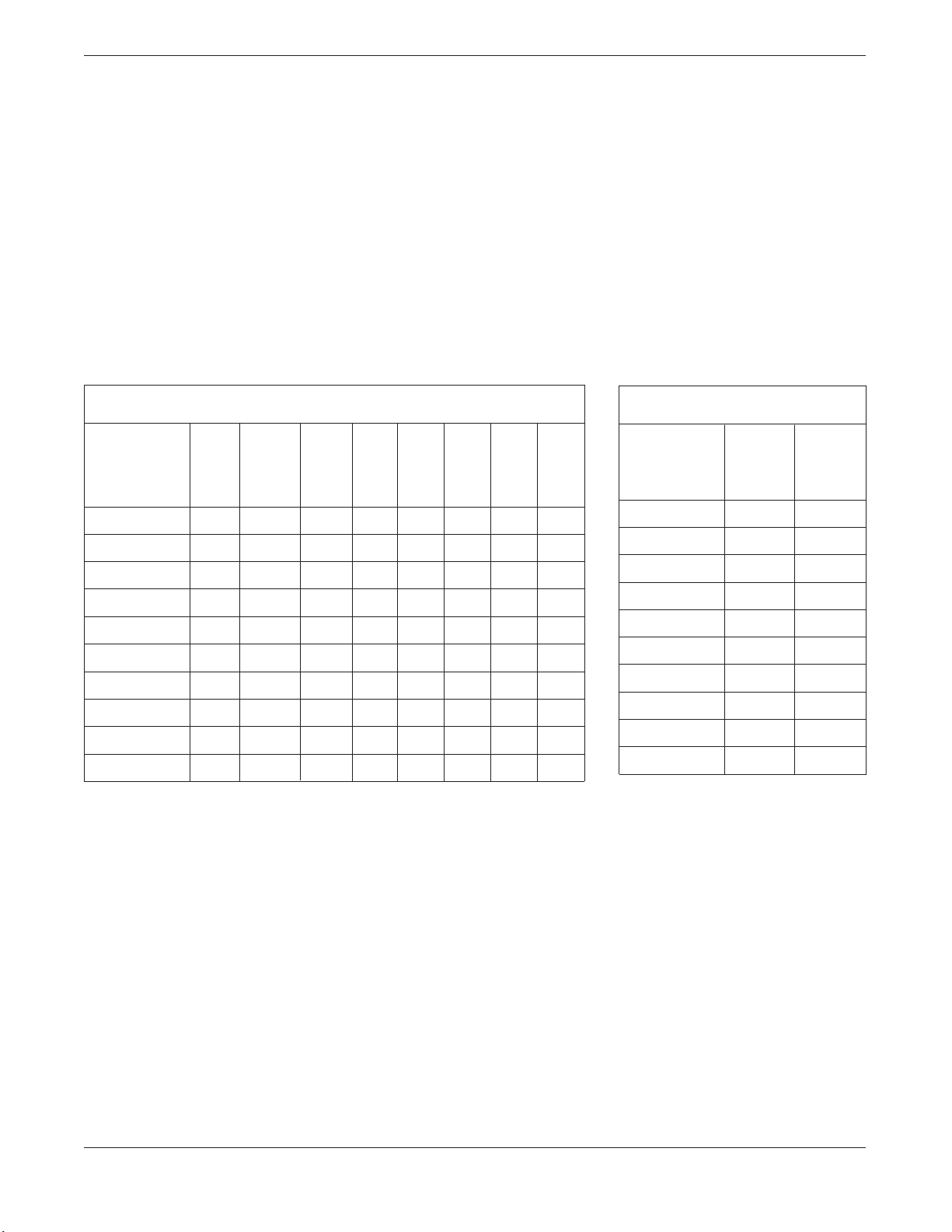
DIMENSIONS AND MAXIMUM TEMPERATURE
Ext. Ext. Ext. Int. Int. Int. Max Max
Width Depth Height Width Depth Height Oper. Oper.
mm mm mm mm mm mm Temp Temp
Model °
F
200NDNL 445 584 473 343 559 330 230 110
300NDNL 445 584 657 343 559 514 230 110
700NDNL 775 584 692 673 559 514 230 110
950NDNL 1143 584 508 1041 559 330 230 110
1600NDNL 445 838 1568 343 559 1260 230 110
200CT 445 629 508 343 559 330 230 110
300CT 445 629 692 343 559 514 230 110
700CT 775 629 692 673 559 514 230 110
300OC 1499 343 372 1397 318 229 230 110
250PNDT 540 508 845 438 483 702 230 110
WEIGHT
Net Shipping
Weight Weight
°
C
Model
200NDNL 46.27
300NDNL
700NDNL
950NDNL
Kg Kg
70.31
55.79 83.91
78.47 105.69
77.11 140.61
1600NDNL 109.35 183.76
200CT
300CT
700CT
300 OC
46.72 72.54
57.15 86.18
85.73 120.20
72.57 106.59
250 PNDT 76.20 92.08
— 4 —
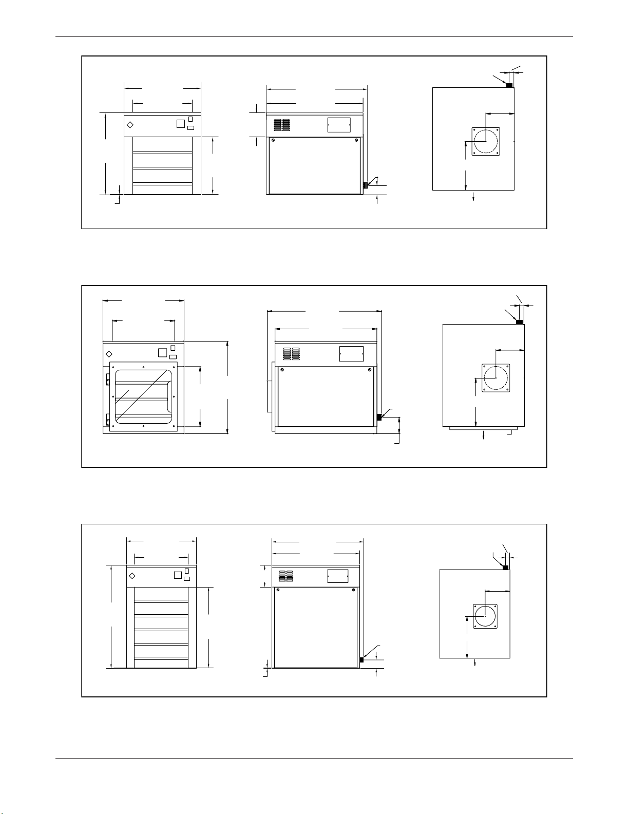
473 mm
Ext.
Height
3,2 mm
Base
445mm
Ext. Width
343 mm
Int. Width
Thermodyne
FRONT VIEW
584 mm
Ext. Depth
559 mm
Int. Depth
140 mm
P.H.
330 mm
Int.
Height
Electrical
55 mm
SIDE VIEW
Figure 1. Outline Dimensional Drawing, 200NDNL
25 mm
Cord & Plug
156 mm
267 mm
Front
PLAN VIEW
445mm
Ext. Width
343 mm
Int. Width
Thermodyne
FRONT VIEW
Thermodyne
445 mm
Ext. Width
343 mm
Int. Width
629 mm
Ext Depth
559 mm
Int. Depth
508 mm
Int.
Ext.
Height
Electrical
89 mm
330 mm
Height
SIDE VIEW
Figure 2. Outline Dimensional Drawing, 200CT
584 mm
Ext. Depth
559 mm
Int. Depth
140 mm
P.H.
25 mm
Cord & Plug
156 mm
267 mm
Front
PLAN VIEW
25 mm
Cord & Plug.
156 mm
657 mm
Ext.
Height
FRONT VIEW
514 mm
Int.
Height
Electrical
3,2 mm
Base
SIDE VIEW
55 mm
Figure 3. Outline Dimensional Drawing, 300NDNL
— 5 —
267 mm
Front
PLAN VIEW
692 mm
Ext.
Height
445 mm
Ext. Width
343 mm
Int. Width
Thermodyne
514 mm
Int.
Height
629 mm
Ext. Depth
559 mm
Int. Depth
Cord & Plug.
25 mm
156 mm
267 mm
Electrical
372 mm
Ext.
Height
FRONT VIEW
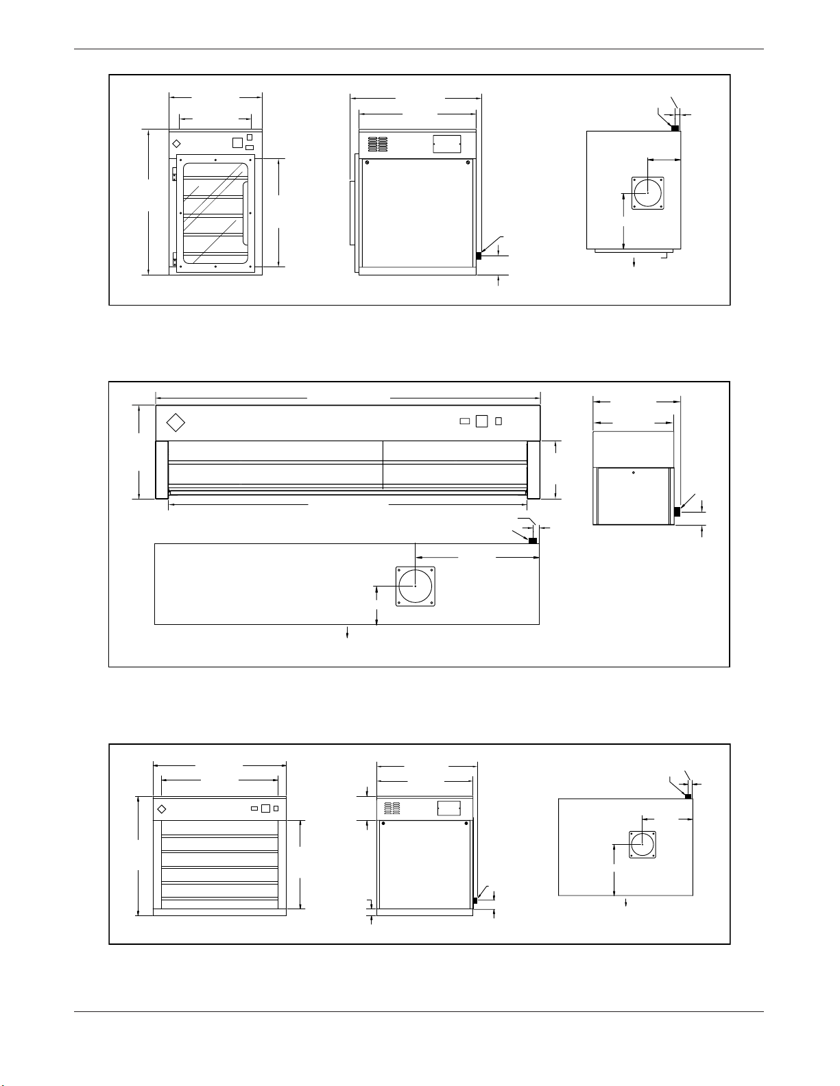
Figure 4. Outline Dimensional Drawing, 300CT
Thermodyne
1499 mm Ext. Width
1397 mm Int. Width
FRONT VIEW
152 mm
Front
PLAN VIEW
SIDE VIEW
89 mm
25 mm
Cord & Plug
483 mm
229 mm
Int.
Height
Front
PLAN VIEW
343 mm
Ext. Depth
318 mm
Int. Depth
SIDE VIEW
Electrical
55 mm
692 mm
Ext.
Height
Ext. Width
Int. Width
Thermodyne
FRONT VIEW
Figure 5. Outline Dimensional Drawing, 300OC
775 mm
673 mm
514 mm
Int.
Height
140 mm
P.H.
38 mm
Base
564 mm
Ext. Depth
559 mm
Int. Depth
SIDE VIEW
Electrical
55 mm
Figure 6. Outline Dimensional Drawing, 700NDNL
— 6 —
Cord & Plug.
295 mm
Front
PLAN VIEW
25 mm
292 mm
 Loading...