

Thermodyne 1200DW Installation Manual
INSTALLATION &
OPERATION MANUAL
MODELS
1200DW
1900DW
1900DWDT
For additional information on Thermodyne Foodservice Products, Inc.,
or to locate an authorized parts and service provider in your area,
Thermodyne Foodservice Products, Inc.
4418 New Haven Avenue 1-800-526-9182
Fort Wayne, IN 46803 www.tdyne.com
Rev. D (07-09)
2100DW
3000P
6000P
visit our website at www.tdyne.com
IMPORTANT FOR YOUR SAFETY
WARNING
IMPROPER INSTALLATION, ADJUSTMENT, ALTERATION,
SERVICE OR MAINTENANCE CAN CAUSE PROPERTY
DAMAGE, INJURY OR DEATH.
READ THE INSTALLATION, OPERATING AND
MAINTENANCE INSTRUCTIONS THOROUGHLY BEFORE
INSTALLING OR SERVICING THIS EQUIPMENT. SERVICE
WORK SHOULD BE PERFORMED BY A LICENSED
PROFESSIONAL, QUALIFIED TO SERVICE AND REPAIR
ELECTRIC FOOD SERVICE EQUIPMENT.
IN THE EVENT OF A POWER FAI LURE,
DO NOT ATTEMPT TO OPERATE THIS DEVICE.
C AUTION
These models have glass doors. Remove carton carefully.
C AUTION
Packaging may have sharp edges and banding material;
use leather work gloves and safety glasses when unpacking.
— 2 —

TABLE OF CONTENTS
IMPORTANT FOR YOUR SAFETY ................................................................................................... 2
INTRODUCTION ............................................................................................................................ 4
GENERAL .................................................................................................................................. 4
SPECIFICATIONS ...................................................................................................................... 4
DIMENSIONAL DRAWINGS ...................................................................................................... 5
UNPACKING ............................................................................................................................... 8
Thermodyne Damaged Goods Policy ................................................................................... 8
INSTALLATION CODES AND STANDARDS .............................................................................. 8
INSTALLATION ........................................................................................................................... 8
LOCATION .................................................................................................................................. 9
ELECTRICAL CONNECTION .................................................................................................... 9
ELECTRICAL SPECIFICATIONS ............................................................................................... 9
OPERATION ................................................................................................................................... 10
CONTROLS AND INDICATORS............................................................................................... 10
STARTUP ................................................................................................................................ 10
Setting Temperature ............................................................................................................ 10
Preheating .......................................................................................................................... 11
FLUID REPLENISHMENT .............................................................................................................. 11
CLEANING AND MAINTENANCE ................................................................................................. 12
WHEN TO CLEAN .................................................................................................................... 12
HOW TO CLEAN ...................................................................................................................... 12
Cleaning Safeguards .......................................................................................................... 12
Sterilizing Stainless Steel ................................................................................................... 12
Cleaning Heat Transfer Shelves .......................................................................................... 12
Stainless Steel Cabinet ....................................................................................................... 13
Door Gasket ........................................................................................................................ 13
CHANGING FLUID ................................................................................................................... 13
TROUBLESHOOTING .................................................................................................................... 15
SCHEMATIC WIRING DIAGRAMS ................................................................................................ 16
WARRANTY ................................................................................................................................... 19
HEAT TRANSFER FLUID MSDS ................................................................................................... 19
— 3 —
INTRODUCTION
GENERAL
The cabinets described in this manual are
programmable for the desired holding temperature.
Thermodyne cabinets are produced with quality
workmanship and materials. Thoroughly read
this manual and carefully follow all instructions
to ensure proper installation, operation and
maintenance, which will result in many years of
The factory setting is 185° F (85ºC) unless
otherwise specified. Each shelf in the cabinet
maintains an exact temperature allowing for
extended holding times; without sacrificing
appearance or taste.
satisfactory performance.
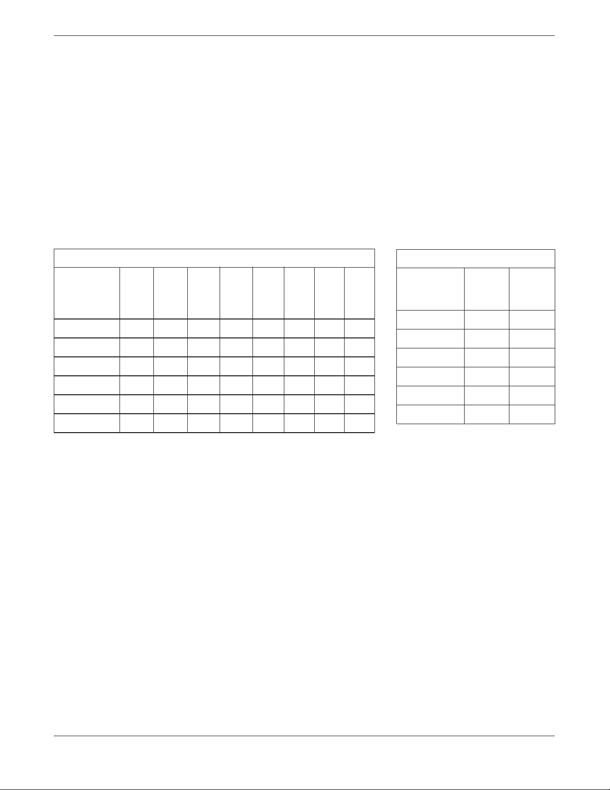
SPECIFICATIONS
DIMENSIONS AND MAXIMUM TEMPERATURE
Width Depth Height Width Depth Height Oper. Oper.
inches inches inches inches inches inches Temp Temp
Model
1200DW 30.50 25.88 42.75 26.50 22.50 29.25 230 110
1900DW 30.50 25.88 75.00 26.50 22.50 58.50 230 110
1900DWDT 30.50 25.88 75.00 26.50 22.50 58.50 230 110
2100DW 43.00 30.25 75.00 39.00 26.81 58.50 230 110
3000P 20.00 36.88 77.63 16.00 33.50 64.30 230 110
6000P 36.00 36.88 77.63 32.00 33.50 61.13 230 110
Ext. Ext. Ext. Int. Int. Int. Max Max
°
F
°
WEIGHT
Weight Weight
Model
C
lbs lbs
Net Shipping
1200DW 249 360
1900DW 449 520
1900DWDT 449 520
2100DW 480 550
3000P 425 560
6000P 850 1112
— 4 —
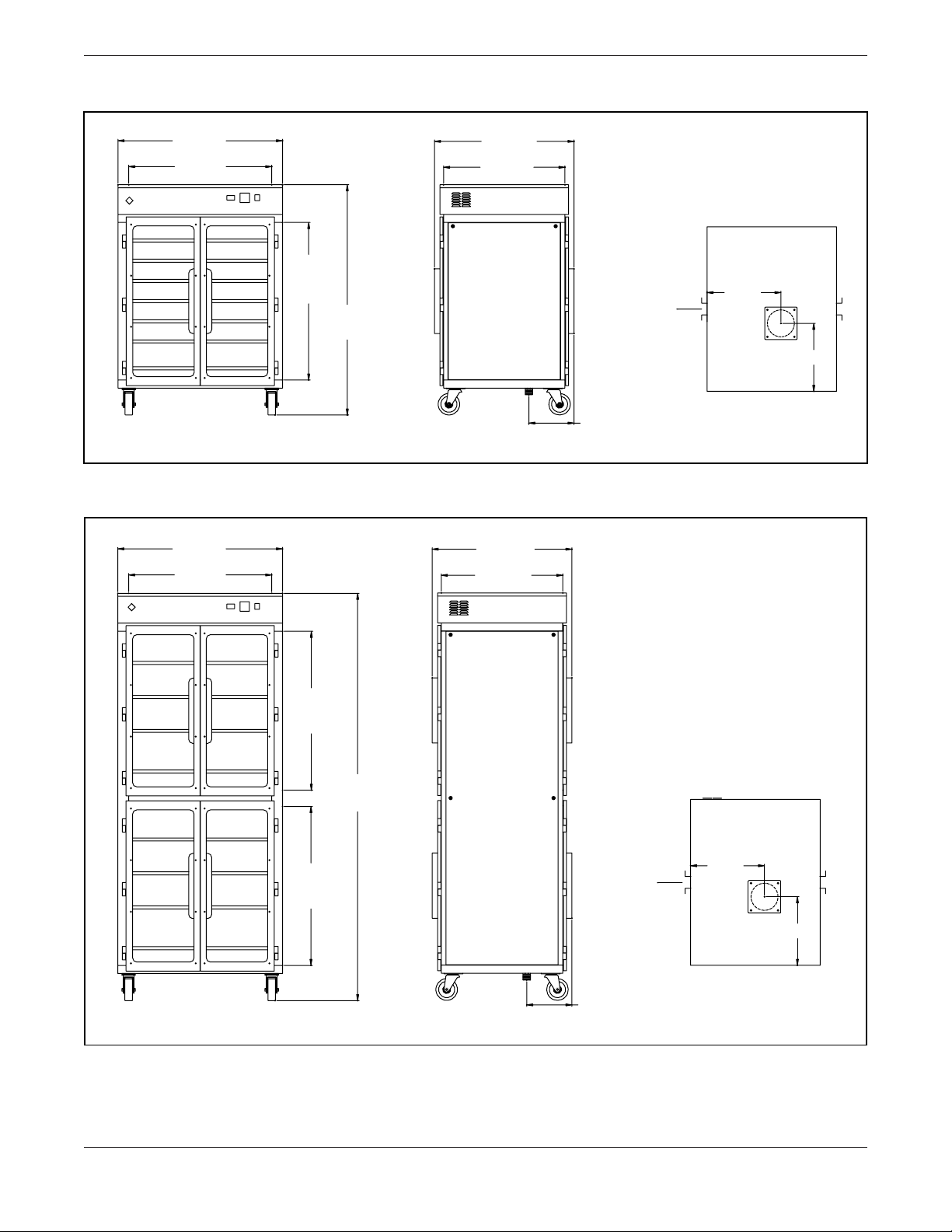
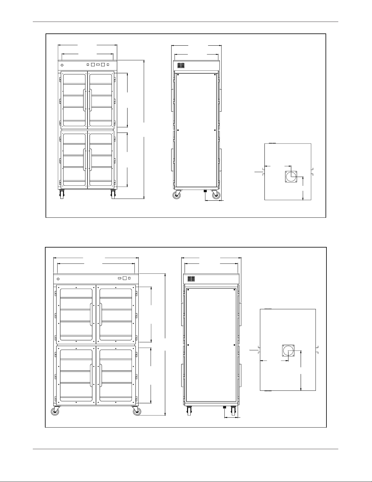
DIMENSIONAL DRAWINGS
"
Front
42 3/4"
Ext.
Height
13 5/8"
12 5/8"
8 3/8"
Cord & Plug
FRONT VIEW
SIDE VIEW
PLAN VIEW
29 1/4"
Lower
Int.
Height
30 1/2"
Ext. Width
26 1/2"
Int. Width
25 7/8"
Ext. Depth
22 1/2"
Int. Depth
Thermodyne
.
75"
Ext.
Height
13 5/8"
12 5/8"
8 3/8"
Cord & Plug
FRONT VIEW
SIDE VIEW
PLAN VIEW
29 1/4"
Upper
Int.
Height
29 1/4"
Lower
Int.
Height
30 1/2"
Ext. Width
26 1/2"
Int. Width
25 7/8"
Ext. Depth
22 1/2"
Int. Depth
Thermodyne
Front
Figure 1. Outline Dimensional Drawing, 1200DW
Figure 2. Outline Dimensional Drawing, 1900DW
— 5 —
75"
Ext.
Height
13 5/8"
12 5/8"
8 3/8"
Cord & Plug
FRONT VIEW
SIDE VIEW
PLAN VIEW
29 1/4"
Upper
Int.
Height
29 1/4"
Lower
Int.
Height
30 1/2"
Ext. Width
26 1/2"
Int. Width
25 7/8"
Ext. Depth
22 1/2"
Int. Depth
Thermodyne
Front
Figure 3. Outline Dimensional Drawing, 1900DWDT
14 1/4"
21 1/8"
.
75"
Ext.
Height
6 3/4"
Cord & Plug
FRONT VIEW
SIDE VIEW
PLAN VIEW
29 1/4"
Upper
Int.
Height
29 1/4"
Lower
Int.
Height
43"
Ext. Width
39 "
Int. Width
30 1/4"
Ext. Depth
26 13/16"
Int. Depth
Thermodyne
Front
Figure 4. Outline Dimensional Drawing, 2100DW
— 6 —
 Loading...