

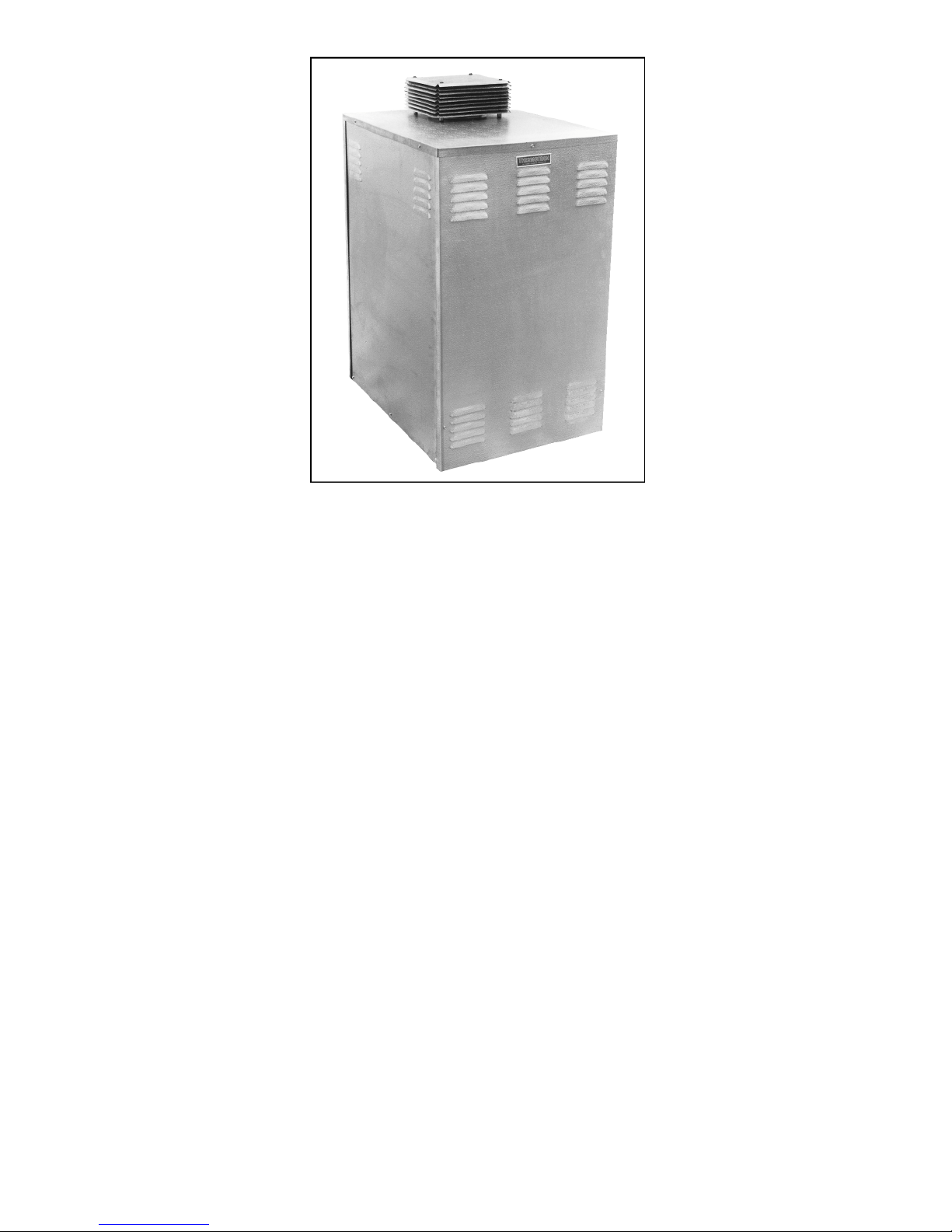
Thermo-Dynamics Boiler THERMOTRON OTF, THERMOTRON ITF Operation, Maintenance, And Installation Instructions

THERMOTRON
ROUTE 61 • P.O. BOX 325 • SCHUYLKILL HAVEN, PA 17972 • (570) 385-0731 • FAX (570) 385-5304
Operation
Thermo-Dynamics
www.thermodynami c s b o i ler.com
Maintenance
and
Installation
Instructions
Models OTF / ITF
Contents
Assembly Diagrams
General Information ......................................................................................................1
Service Policy ................................................................................................................1
Installation Instructions .................................................................................................2
Filling Instructions .........................................................................................................2
Winterizing .....................................................................................................................3
Start-Up and Operation ................................................................................................3
Piping/Connection Diagrams .......................................................................................4
......................................................................................................5
Trouble Shooting ..........................................................................................................6
Care and Maintenance .................................................................................................6
Pool Coil Diagram .........................................................................................................7
Wiring Diagrams ...........................................................................................................8
Parts List ........................................................................................................................9
Specifications ..........................................................................................................10
Home Owner Information .......................................................................................11
Set-Up and Service Records ..................................................................................12
Warranty Information ..............................................................................................12

1
General Information
nance. Proper care and maintenance of your pool heater will allow you to enjoy the benefits of your
with a high quality trouble free product that will be part of your family for many years to come.
1) Please read all instructions and review all diagrams prior to proceeding with installation.
2) Instructions and diagrams are intended only as guidelines.
3) Installations must conform with all applicable national, state and local codes.
4) Additional guidelines are available from National Fire Protection Association (NFPA), American
society of Mechanical Engineers (ASME) and Building Officials and Code Administrators
(BOCA).
Service Policy
Congratulations on the purchase of your new pool heater. Here at Thermo-Dynamics Boiler
Company we pride ourselves on the design and construction of our product. Our intent is to furnish
you with a high quality appliance that will provide you and your family with years of trouble free
service.
In order to maintain peak performance of your pool heater, it is recommended that the unit be winterized at the end of the season and that the burner/boiler be serviced annually. Servicing of your
appliance must be performed by a qualified heating technician. You should utilize a qualified heating technician familiar with your installation to manage your heater and perform periodic mainte-
new purchase as well as extend its long useful life.
In the event that your serviceman encounters difficulty with the pool heater, he/she shall contact
the distributor from which the product was purchased. The distributor shall, in turn, contact the
Thermo-Dynamics sales representative for your area. By adhering to this protocol, ThermoDynamics wishes to provide you with responsive and unparalleled service. We realize the importance that our product means to you and your family and our goal is to get your heater up and running as quickly as possible.
Thank you for purchasing the Thermo-Dynamics pool heater. Again, it is our intent to provide you
Please consider Thermo-Dynamics Boiler Company in the future for all of your home heating
needs.

2
Section I. Installation Instructions Control of combustion draft.
(1)
Locating The Heater:
pool circulation lines are at the back of
component to obtaining optimum
open take temperature readings for
(B)
ITF Series (Indoor Units)
two (2) feet higher than any portion of
pitched upward at least one-quarter
joint should be securely fastened with
effect the shortest possible run of
an indirect heater using primary water
water
Therefore the pool heater, or boiler
Before uncrating the unit prepare
the location. It should be placed upon
a good level concrete floor or pad.
Care should be taken to locate the
unit for easy accessibility. Please
maintain the following clearances to
combustible materials:
OTF
(Outdoor Pool Heaters)
Front 24 inches
Back 24 inches
Sides 12 inches
ITF
(Indoor Pool Heaters)
Front 24 inches
Back 12 inches
Sides 12 inches
In addition, the air openings in the
cabinet shall have adequate clearance
to allow for sufficient air intake to the
burner. Uncrate the unit as close to
its permanent location as possible to
prevent handling damage.
(2) Connections:
Do not run any piping along the
front access panel of heater as they
may interfere with servicing. The tappings for connecting the unit to the
the heater. These connections are 11/2" NPT. Connections should be
made as per the piping illustration on
page 4. Install unions at the heat
exchanger so it can be readily
removed for service. If plastic pipe is
used, make connection to the unit with
metal piping and run metal piping to
the floor line before joining to plastic
pipe. This will act as a “heat-trap” and
reduce possible damage to the plastic
pipes from overheating. Install positive check valve on inlet side. Install a
Tee joint at the coil where the PIPING
FROM the pool filter/pump ENTERS
the coil. Install the copper well provided into the piping Tee and insert the
remote sensing bulb from the L-4031
pool thermostat.
An adjustable by-pass around the
heat-exchanger is required. The bypass is an important and necessary
performance (see piping diagram on
page 4). In order to properly adjust
the flowrate through the system,
please adhere to the following steps:
By-Pass Set-Up
a) Use piping and full-size valve
to connect the “In” and “Out” streams
of the pool coil.
b) With the bypass valve wide
open take a pressure reading at the
gauge on the pool filter.
c) Pressure reading with bypass
valve full open is the baseline pressure.
d) Slowly close the bypass valve
so that the pressure increases.
e) Stop when pressure reaches 2
to 4 psi above the baseline at the filter.
Alternatively, flowrate may be set
by comparing the temperature differ-
ence between the “In” and “Out”
streams of the pool coil.
a) Use full size piping and valve
to connect the “In” and “Out” streams
of the pool coil.
b) Allow the boiler to fire continuously for a period of ten (10) to fifteen (15) minutes.
c) With the bypass valve wide
the coil.
d) Note: surface temperature
readings taken on a cold day will vary
significantly from test data.
e) Slowly close the bypass valve
and continue to take temperature
readings.
f) Stop when the temperature
difference between the “In” and “Out”
streams reaches forty-five (45) to fifty
(50) degrees Fahrenheit.
g) Flowrate should correspond to
six (6) gallons per minute. (See chart
page 7).
(3) Flue Connections:
(A) OTF Series (Outdoor Units)
The OTF heaters are provided with
an outdoor vent cap to be installed
directly on top of the cabinet at the flue
outlet. This vent cap provides for a
waterproof unit as well as proper con-
(a) General:
Oil fired units must be connected
to a flue having sufficient draft at all
times to assure proper operation.
(b) Draft:
A draft regulator should be
installed in accordance with the man-
ufacturer’s instructions. Set the draft
to a negative –.01 to –.02 max. WC
over the fire.
(c) Roof Clearances:
The flue gas exit of the venting
system should be at least three (3)
feet above the outside point where it
passes through the roof and at least
a building within ten (10) feet of the
venting system.
(d) Chimney Connections:
The horizontal length of a chimney connector should not exceed ten
(10) feet unless a draft booster is
used. The connector should be
(1/4) inch to the foot. Use only high
quality lock seam smoke pipe. Each
sheet metal screws. Chimney connections should be positioned to
smoke pipe to the chimney.
(e) Vent Cap:
Install a UL listed vent cap where
the possibility of down draft exists.
Section II
Filling
Instructions
The Thermotron Pool Heater is
in the boiler shell to act as a heat
transfer medium to the pool
flowing through the separate all
copper/bronze heat exchanger coil.
section, MUST be filled with fresh city
water. DO NOT FILL WITH CHLORINATED OR WATER FROM THE
SWIMMING POOL.
3
(1) Do not turn on electrical
garden hose to the hose adapter of
Open the vent at the top of
When water flows out of
pipe systems as soon as the burner
also be caused by too high a “lift” or
the air band to allow just sufficient air
on the air shutter and closing the air
reading of
power to heater until boiler is properly
filled with water.
(2) * Connect the male end of a
the heater drain valve.
(3)
the boiler section location as shown
on page 4.
(4) Turn on water and open drain
valve, allow water to flow into boiler
section.
(5)
boiler vent, close vent and leave
heater drain valve open until pressure
gauge reads approximately 10 PSI.
(6) Close drain valve and disconnect hose.
(7) Pool temperature control
should be set at desired temperature.
(8) Burner can now be operated
as per specified instructions.
*You may choose to install permanent piping...filling instructions would be the same.
IMPORTANT NOTICE
Winterizing The Heater:
If the pool heater is installed in an
area known to have a freezing climate
it is necessary to COMPLETELY drain
both the primary boiler and indirect
heat exchanger (pool coil).
Connect a hose to the boiler drain
at the bottom of the boiler section.
Open the vent at the top of the boiler,
as well as the drain valve and drain
the boiler section completely.
Disconnect the unions and the piping
at the pool coil heat exchanger.
Remove the 1/8" pipe plugs in the bottom of the pool coil heat exchanger
header (to be completely certain that
all water is out of the indirect heat
exchanger, it may be advisable to
remove the pool coil completely or
force an anti-freeze solution into the
pool coil.)
Section III
Start Up and
Operation
A Start Up:
(1) Make sure the electrical
power is turned off.
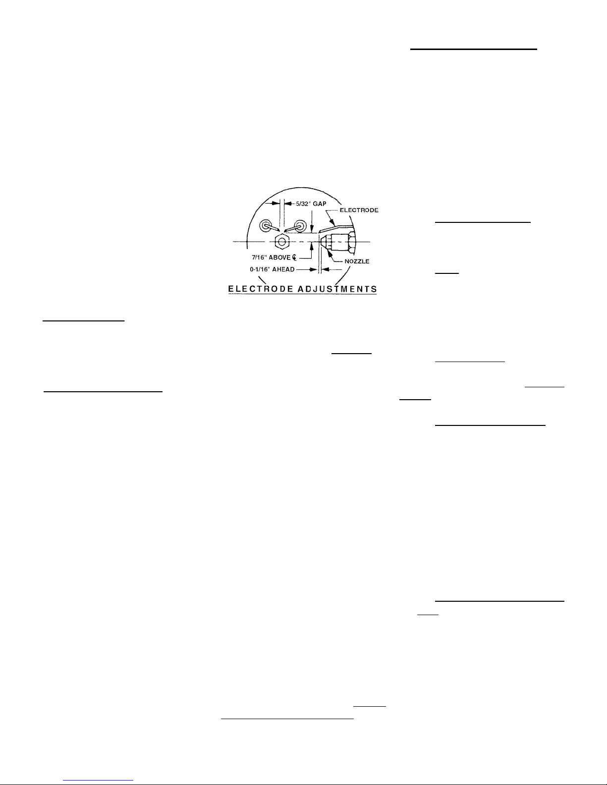
(2) Check the Oil Burner ignition
electrodes carefully and adjust if necessary.
(3) Check to be certain oil tank is
full.
(4) Be certain unit is filled with
water as per filling instructions.
(5) Turn on pool filter pump.
(6) Set limit control at 180°.
(7) Install pressure gauge in the
nozzle port of the fuel pump. Do not
take reading at the bleed port. The
pressure gauge should have a minimum range of 100 PSI. Consult Fuel
Pump specification sheet (shipped
with Oil Burner).
(8) Turn on burner power switch.
(9) Push the safety reset button
on the primary control and release.
(10)Bleed the fuel unit on one-
motor starts. To bleed, attach a piece
of 1/4" OD clear plastic tubing to the
end of the bleed port. Loosen same
and purge oil of air for at least 15 seconds after oil appears to be clear. If oil
stream does not become clear and
free of air bubbles or foam, check all
fittings, filter and valve connections.
Foam can also be caused by kinks in
the oil line, causing an oil vacuum
condition. High vacuum readings can
too small diameter tubing. Consult
Fuel Pump specification sheet.
B Equipment Adjustments:
Equipment Required:
(1) CO2Analyzer (absorption
type)
(2) Draft Gauge
(3) Fuel Pressure
Gauge/Vacuum Gauge
(4) Stack Thermometer
(5) Smoke Tester (Bacharach
Type)
Allow the burner to operate continuously for at least 15 minutes and
then make adjustments:
(a) Combustion Samples:
Should be taken through the
observation port above the burner,
directly over the fire.
(b) Draft:
Take a draft reading over the fire
(OTF outdoor equipment will range
from “0” to –.01 negative minimum).
(ITF indoor equipment should be
adjusted to a –.01 draft minimum to a
–.02 max.)
(c) Pump Pressure:
Adjust the pump discharge pressure to 100 PSI. Vacuum must not
exceed 6" on one pipe and 10" on a
two-pipe system.
(d) Combustion Settings/CO
2
Reduce the air supply by closing
for clean combustion. This is accomplished by loosening the lock screws
shutter until a TRACE of smoke is
recorded. Take a CO2sample, which
should be approximately 12%. Open
the air shutter and lower CO2reading
approximately by 1-1/2 to 2% from the
above reading. A “0” smoke reading
should result with a CO
2
approximately 10%.
(e) Stack Temperature: (ITF
only)
Check to see that the stack temperature is approximately 500° above
the ambient temperature.
(f) Turn LIMIT CONTROL to the
lowest setting; burner should shut
down. Turn back to the desired setting, (normally 180°) burner should
operate.
(g) Turn POOL TEMPERATURE
CONTROL down to lowest setting;
 Loading...