

Thermo-Dynamics Boiler S85, S100, S135, S110, S125 Installation, Operation & Maintenance Manual
...
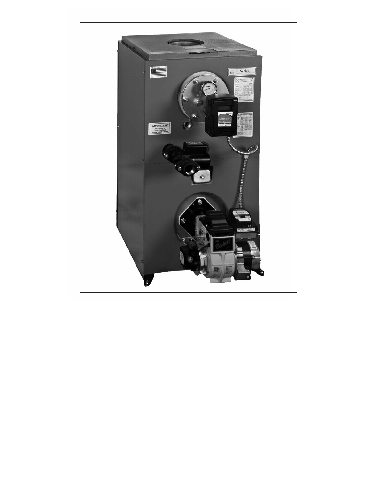
S Series
Installation
Operation
Maintenance
Manual
Thermo-Dynamics Boiler Company
ROUTE 61 • SCHUYLKILL HAVEN, PA 17972
(570) 385-0731 FAX (570) 385-5304
www.thermodynamicsboiler.com

Service Policy
Congratulations on the purchase of your boiler. Here at ThermoDynamics Boiler Company we pride ourselves on the design and construction of our product. Our intent is to furnish you with a high quality appliance
that will provide you and your family with years of trouble free service.
In order to maintain peak performance of your boiler, it is recommended
that the burner/boiler be serviced annually, preferably prior to the onset of
the winter heating season. Servicing of your appliance must be performed
by a qualified heating technician. You should utilize a qualified heating technician familiar with your installation to manage your heater and perform periodic maintenance. Proper care and maintenance of your boiler will allow you
to enjoy the benefits of your new purchase as well as extend its long useful
life.
In the event that your serviceman encounters difficulty with the boiler,
he/she shall contact the distributor from which the product was purchased.
The distributor shall, in turn, contact the Thermo-Dynamics sales representative for your area. By adhering to this protocol, Thermo-Dynamics wishes
to provide you with responsive and unparalleled service. We realize the
importance that our product means to you and your family and our goal is
to get your heater up and running as quickly as possible.
Thank you for purchasing the Thermo-Dynamics boiler. Again, it is our
intent to provide you with a high quality trouble free product that will be part
of your family for many years to come. Please consider Thermo-Dynamics
Boiler Company in the future for all of your home heating needs.
Subject Page
Read This First . . . . . . . . . . . . . . . . . . . . . . . . . . . . . . . . . . . . . . . . . . . . . . . . . . . . . 2
Specifications . . . . . . . . . . . . . . . . . . . . . . . . . . . . . . . . . . . . . . . . . . . . . . . . . . . . . . 4
Installation . . . . . . . . . . . . . . . . . . . . . . . . . . . . . . . . . . . . . . . . . . . . . . . . . . . . . . . . . 4
Operational Sequence . . . . . . . . . . . . . . . . . . . . . . . . . . . . . . . . . . . . . . . . . . . . . . . . 7
Start-Up . . . . . . . . . . . . . . . . . . . . . . . . . . . . . . . . . . . . . . . . . . . . . . . . . . . . . . . . . . 8
Troubleshooting Guide . . . . . . . . . . . . . . . . . . . . . . . . . . . . . . . . . . . . . . . . . . . . . . . A
Dimensions and Jacket Assembly . . . . . . . . . . . . . . . . . . . . . . . . . . . . . . . . . . . . . . B
Specifications . . . . . . . . . . . . . . . . . . . . . . . . . . . . . . . . . . . . . . . . . . . . . . . . . . . . . . C
Piping Diagram . . . . . . . . . . . . . . . . . . . . . . . . . . . . . . . . . . . . . . . . . . . . . . . . . . . . . D
Wiring Diagrams . . . . . . . . . . . . . . . . . . . . . . . . . . . . . . . . . . . . . . . . . . . . . . . . . . . . E
Installer/Serviceman Labels . . . . . . . . . . . . . . . . . . . . . . . . . . . . . . . . . . . . . . . . . . . F
Appendix . . . . . . . . . . . . . . . . . . . . . . . . . . . . . . . . . . . . . . . . . . . . . . . . . . . . . . . . . . G
Contents
Appendices

Read This First
1. Installer must be a trained, experienced technician and should read all
instructions before installation.
2. Inspect the boiler, jacket and all components to be sure damage has not
occurred in shipment. If damage is evident a claim must be filed with the freight
carrier who transported the boiler from the factory to the distributor where it
was purchased. Do not install the boiler. Contact your distributor.
3. Disconnect power supply before connecting wiring.
4. Refer to local codes for oil burning equipment, for recommended installation
practice. You will need to be familiar with NFPA International Standard 31,
“Standard for the Installation of Oil Burning Equipment”.
5. A complete heat loss calculation is necessary to choose the proper size unit to
install. The boiler should be sized to within 25% of the actual heat loss of the
structure. Over sizing will result in short cycling and inefficient operation.
6. When moving the boiler, do not push against the jacket or burner. Damage will
result.
7. If the boiler is vented to a chimney, be certain the chimney is clean and free of
obstructions. The chimney must be masonry with tile lining or metal insulated
with a stainless steel surface. The Chimney must be properly sized. Draft
requirements are essential for safe and proper operation of the boiler.
8. If the boiler is connected to a venting device, make sure that it is listed by a rec ognized testing service. Follow the venting device manufacturer’s installation
instructions. Verify that the venting device installation complies with the recom mendations of the manufacturer and local and state codes.
9. Conduct a thorough checkout when installation is complete. Check for
indications of leaks and make sure that no material is left adjacent to the
boiler.
2

10. The use of low sulfur No. 2 heating oil is highly recommended.
11. Modification, substitution or elimination of factory equipped, supplied or
specified components may result in property damage, personal injury or the
loss of life.
12. The following definitions apply to potential hazards noted in this manual.
DANGER: Indicates a hazardous situation which if not avoided will result in
death or serious injury.
WARNING: Indicates a hazardous situation which if not avoided could result
in death or serious injury.
CAUTION: Indicates a hazardous situation which if not avoided, may result
in a minor injury. It may also warn against unsafe practices that may result in
minor injury or damage to equipment.
NOTICE: Indicates that special attention to information is required. Not
related to personal injury or property damage.
3
A. Installation Instructions
1) Place the boiler on a level floor, preferably raised and as close to the chimney as possible.
The boiler must be installed on a non-combustible surface. The minimum clearances for
installation are shown below. Reduced clearance installations must follow NFPA-31
guidelines. If the boiler is a Knock Down (not packaged for ease of installation), install the
jacket in accordance with the directions provided in the jacket package, prior to piping.
Standard Clearances
Front 24”
Sides 6”
Rear 6”
Chimney Connector 18”
WARNING: The boiler must be installed on a non-combustible surface or fire may result.
2) Install the boiler piping. For location of piping refer to the Installation Drawing.
DANGER: Boilers with tankless coils must be piped in accordance with the piping diagram
including installation of a tempering or mixing valve. Domestic hot water temperatures
exceeding 125°F will cause severe burns instantly or death by scalding.
WARNING: Relief valve discharges and drain valve piping must be piped to a safe place of
discharge.
NOTICE: S Series Boilers are provided with a built-in air scoop feature. This feature allows
quiet, air free operation of the hot water system by eliminating air pockets without installa tion of air scoops. The supply line tapping in the top of the boiler extends approximately 1
inch below the top of the boiler, allowing only air-free water to enter the heating system
supply. Any air trapped in the top of the boiler is purged through the 3/4” vent tapping.
The 3/4” vent tapping should be connected to an automatic float vent, a manual vent or
piped to a conventional expansion tank. See Appendix B for illustration.
3) Packaged boilers are shipped with the burner, aquastat and circulator installed and wired at
the factory. See the Basic Wiring Diagram for wiring schematic. See component manufac turer’s manual for wiring instructions.
4) An expansion tank, not provided, must be matched to the system and installed in accor dance with the manufacturer’s instructions. Do not undersize the expansion tank. An
automatic feed and pressure reducing valve, not provided, should be installed in the water
inlet line to keep the entire system from falling below the pressure setting of the valve (
about 12 psi) See the feed valve suppliers instructions for maximum allowed water supply
pressure and requirements for pressure reducers. For piping and wiring of other system
components see the manufacturer’s installation manuals.
5) The tank-less water heater may be piped as shown in the Installation Drawing. A mixing
4

valve (tempering valve), not supplied, must be used to reduce the water temperature at
kitchen or bathroom taps. High temperature water for a dishwasher may be obtained by
piping as shown in the Installation Drawing. The nuts that secure the tank-less coil flange
should be tightened before the boiler is filled with water, after initial firing and once a year
during the annual maintenance.
CAUTION: Deterioration due to coil gasket leaks will void the warranty.
6) Connect boiler flue outlet to chimney using galvanized smoke pipe. Use only high quality
lock seam smoke pipe. The flue pipe should be pitched upward at least 1/4" per foot of run.
Refer to the boiler specifications for proper size flue pipe for your model boiler. Use only
elbows and straight sections. Tees may be used in a straight section in conjunction with a
barometric draft regulator however they must not be used for a 90° turn. Each joint should
be securely fastened with sheet metal screws. The flue pipe must not be inserted beyond
the inside wall of the chimney. Install barometric draft regulator in the horizontal or vertical
section of the flue pipe. The draft regulator should be installed in accordance with the
manufacturer’s instructions. Set the draft to in the stack as specified in the boiler specifica tions and on the Installer/Serviceman Label on the boiler jacket. The flue gas exit of the
venting system should be at designed with clearances in accordance with NFPA 31. A
chimney must be at least 3 feet above the highest point where it passes through the roof
and at least 2 feet higher than any portion of a building within 10 feet of the venting system.
The horizontal length of a chimney connector should not exceed 10 feet unless a draft
booster is used. Where the possibility of down drafts exist, install a listed vent cap.
WARNING: Installation and venting with improper materials or methods may result in
serious injury or death due to asphyxiation from poisonous gases such as carbon
monoxide. A carbon monoxide detector should be installed per the manufacturer’s
instructions.
7) The boiler room must be well ventilated to allow sufficient make-up air to support combus tion. Lack of adequate combustion air may result in erratic operation of the burner, noisy
combustion or fuel odors. Remember your need for outside air will be greatly increased if
you have a vented dryer in the basement or other venting fans in the home. Boilers located
in confined spaces shall be provided with two permanent openings, one near the top and
one near the bottom of the enclosure. Each opening shall have a free area of not less than
one square inch per 1000 BTU per hour input rating of the boiler, freely communicating with
interior areas having adequate infiltration from the outside.
8) Fill boiler and system with water. Be sure entire system has been purged of air and the
desired pressure is obtained. Leak-check the boiler and piping system by turning off the
make-up water supply and observing the boiler pressure gage. A loss of pressure indicates
a system leak that must be repaired prior to operating the boiler.
9) Remove the nozzle line assembly and check that the correct nozzle is installed for the
desired firing rate. Check that burner settings are correct for the nozzle that is installed.
See the Installer/Serviceman Label.
10) Connect burner to oil supply. Refer to fuel unit manufacturer literature for piping, connec tions, lift and tank installation. If such information is unavailable use the following guide
lines.
5

FUEL UNITS/FUEL LINES
Fuel supply "level with" or "above" burner: A single stage fuel unit connected to the fuel sup-
ply with a single supply line is the most common type of installation for these conditions. Manual
venting of the fuel unit is usually required on initial start-up. Failure to vent air could result in an
air lock/oil starvation condition. (One pipe)
Fuel supply below the level of burner:
Use a single stage fuel unit in lift conditions of up to 10
ft., and a two stage fuel unit when the lift exceeds 10 ft. Both conditions require the use of a
return line which purges the fuel unit of air returning it to the fuel tank. The "by-pass" plug must
be inserted into the fuel unit when installing a return line. (Two pipe)
Fuel line installation:
Continuous lengths of heavy wall copper tubing are recommended and
should be installed under the floor when possible. Always use flare fittings. Always install fittings
in accessible locations. Never use teflon tape on any fuel fitting. Use of teflon will void any warranty. Fuel lines should not run against the appliance or the ceiling joists.
Fuel line valve and filter:
Install two high quality shutoff valves in accessible locations on the
oil supply line. Locate one close to the tank and the other close to the burner ahead of the filter.
Some filters come with built-in shutoff valves. Install a generous capacity filter inside the building
between the fuel tank shutoff valve and the burner locating both the filter and the valve close to
the burner for ease of servicing.
CAUTION: All oil feed lines to burners must be air tight. Use only flare fittings when assembling
oil lines since the slightest air leak, caused by loose fittings, bad gaskets or any other reason,
can cause a foaming oil stream which will cause any of the following conditions:
a) Intermittent firing, causing safety shutdown
b) Poor starts
c) Smokey starts
d) Continual sooting of boiler and burner parts including the cad cell
e) Reduced firing rate, inefficient operation and erratic fire pattern
f) A dangerous combustion condition, allowing the firebox to fill with a lean mixture (too
much air in the oil stream) which could cause a delay in ignition of the fuel mixture until
the danger point has been reached.
Suction Vacuum Test. A fuel pump suction vacuum test should be performed. See the fuel
pump manufacturers literature for details. The suction vacuum must be limited to ensure that
there is adequate pump lift. This problem becomes proportionately larger with underground
tanks. If the following procedures are followed, burner related problems will be minimized:
a) Connect vacuum gauge to oil pump. Suction vacuum must not exceed 10 inches of mercury
for single stage pumps and 15 inches for two stage pumps. It is preferable to stay below
these limitations.
b) When the suction line is tight and properly installed the pump will hold its vacuum for a
minimum of 60 minutes after shutdown.
c) Installation of a check valve in the suction line of a two pipe system is advisable under all
circumstances. Be sure the check valve fittings are airtight.
6

11) Connect the electric supply to the boiler as indicated on the wiring diagram. The wiring
must be installed in accordance with the National Electrical Code and any other state and
local codes and the following requirements.
a) Internal wiring is completed at the factory on packaged boilers. External wiring must con
form with the National Electric Code and local codes.
b) Field connections should be protected with a 15 amp fuse.
c) A separate, fused disconnect switch should be installed and located near the unit so that
power can be shut-off for servicing, unless already equipped.
d) Install the room thermostat (not provided) on an inside wall away from cold drafts, windows
or heat from fireplaces, appliances or sunlight. Set the heat anticipator in accordance with
the manufacturer’s instructions. Connect the thermostat leads to the “TT” terminals on the
circulator control.
C. Operational Sequence
1) S Boilers equipped with tankless coil are equipped with a combination aquastat control
which has high and low limits to be set at 180° F and 160° F respectively by the installer.
These settings are nominal and may be adjusted for the particular installation conditions.
A 20° F difference between high and low limit is recommended. The control prioritizes
domestic hot water heating as explained below.
a. When room temperature falls below thermostat setting, thermostat calls for heat starting
the burner and circulating pump. The burner and pump continue to operate until room
heating requirements are satisfied (thermostat setting is reached), or until boiler water
temperature reaches the high limit control temperature setting. If the high limit control
temperature setting is reached, the burner shuts off and the circulating pump continues
to operate until the room heating requirements are satisfied. If the thermostat continues
to call for heat after the boiler water temperature has dropped to approximately 10
degrees below the temperature setting of the high limit control, the oil burner will start
again and the circulating pump will continue to run.
b. The boiler water temperature is normally maintained at 160°F around the tankless coil by
the operating control so that an abundance of hot water is available. If the boiler water
temperature should fall approximately 10 °F below the operating control low limit setting,
the oil burner will be started again by the control (and the circulating pump will be pre
vented from operating) until the operating control setting is satisfied. The operating con trol has an adjustable low limit differential setting. The low limit differential setting deter mines how high the boiler temperature must rise before the burner turns off and or the
circulator comes on if the thermostat calls for heat. The differential is measured from
10°F below the low limit. See control manufacturer’s literature included in the data pack age for detailed wiring, operating and safety instructions.
c. Adjusting the low limit differential to higher values will provide priority to heating domestic
hot water over a greater range of boiler temperature. (Maximum of approximately 25°F
differential measured from 10°F below the low limit setting.)
7
 Loading...