

Thermo-Dynamics Boiler S85, S100, S135, S110, S125 Installation, Operation & Maintenance Manual
...Page 1

S Series
Installation
Operation
Maintenance
Manual
Thermo-Dynamics Boiler Company
ROUTE 61 • SCHUYLKILL HAVEN, PA 17972
(570) 385-0731 FAX (570) 385-5304
www.thermodynamicsboiler.com
Page 2

Service Policy
Congratulations on the purchase of your boiler. Here at ThermoDynamics Boiler Company we pride ourselves on the design and construction of our product. Our intent is to furnish you with a high quality appliance
that will provide you and your family with years of trouble free service.
In order to maintain peak performance of your boiler, it is recommended
that the burner/boiler be serviced annually, preferably prior to the onset of
the winter heating season. Servicing of your appliance must be performed
by a qualified heating technician. You should utilize a qualified heating technician familiar with your installation to manage your heater and perform periodic maintenance. Proper care and maintenance of your boiler will allow you
to enjoy the benefits of your new purchase as well as extend its long useful
life.
In the event that your serviceman encounters difficulty with the boiler,
he/she shall contact the distributor from which the product was purchased.
The distributor shall, in turn, contact the Thermo-Dynamics sales representative for your area. By adhering to this protocol, Thermo-Dynamics wishes
to provide you with responsive and unparalleled service. We realize the
importance that our product means to you and your family and our goal is
to get your heater up and running as quickly as possible.
Thank you for purchasing the Thermo-Dynamics boiler. Again, it is our
intent to provide you with a high quality trouble free product that will be part
of your family for many years to come. Please consider Thermo-Dynamics
Boiler Company in the future for all of your home heating needs.
Page 3
Subject Page
Read This First . . . . . . . . . . . . . . . . . . . . . . . . . . . . . . . . . . . . . . . . . . . . . . . . . . . . . 2
Specifications . . . . . . . . . . . . . . . . . . . . . . . . . . . . . . . . . . . . . . . . . . . . . . . . . . . . . . 4
Installation . . . . . . . . . . . . . . . . . . . . . . . . . . . . . . . . . . . . . . . . . . . . . . . . . . . . . . . . . 4
Operational Sequence . . . . . . . . . . . . . . . . . . . . . . . . . . . . . . . . . . . . . . . . . . . . . . . . 7
Start-Up . . . . . . . . . . . . . . . . . . . . . . . . . . . . . . . . . . . . . . . . . . . . . . . . . . . . . . . . . . 8
Troubleshooting Guide . . . . . . . . . . . . . . . . . . . . . . . . . . . . . . . . . . . . . . . . . . . . . . . A
Dimensions and Jacket Assembly . . . . . . . . . . . . . . . . . . . . . . . . . . . . . . . . . . . . . . B
Specifications . . . . . . . . . . . . . . . . . . . . . . . . . . . . . . . . . . . . . . . . . . . . . . . . . . . . . . C
Piping Diagram . . . . . . . . . . . . . . . . . . . . . . . . . . . . . . . . . . . . . . . . . . . . . . . . . . . . . D
Wiring Diagrams . . . . . . . . . . . . . . . . . . . . . . . . . . . . . . . . . . . . . . . . . . . . . . . . . . . . E
Installer/Serviceman Labels . . . . . . . . . . . . . . . . . . . . . . . . . . . . . . . . . . . . . . . . . . . F
Appendix . . . . . . . . . . . . . . . . . . . . . . . . . . . . . . . . . . . . . . . . . . . . . . . . . . . . . . . . . . G
Contents
Appendices
Page 4

Read This First
1. Installer must be a trained, experienced technician and should read all
instructions before installation.
2. Inspect the boiler, jacket and all components to be sure damage has not
occurred in shipment. If damage is evident a claim must be filed with the freight
carrier who transported the boiler from the factory to the distributor where it
was purchased. Do not install the boiler. Contact your distributor.
3. Disconnect power supply before connecting wiring.
4. Refer to local codes for oil burning equipment, for recommended installation
practice. You will need to be familiar with NFPA International Standard 31,
“Standard for the Installation of Oil Burning Equipment”.
5. A complete heat loss calculation is necessary to choose the proper size unit to
install. The boiler should be sized to within 25% of the actual heat loss of the
structure. Over sizing will result in short cycling and inefficient operation.
6. When moving the boiler, do not push against the jacket or burner. Damage will
result.
7. If the boiler is vented to a chimney, be certain the chimney is clean and free of
obstructions. The chimney must be masonry with tile lining or metal insulated
with a stainless steel surface. The Chimney must be properly sized. Draft
requirements are essential for safe and proper operation of the boiler.
8. If the boiler is connected to a venting device, make sure that it is listed by a rec ognized testing service. Follow the venting device manufacturer’s installation
instructions. Verify that the venting device installation complies with the recom mendations of the manufacturer and local and state codes.
9. Conduct a thorough checkout when installation is complete. Check for
indications of leaks and make sure that no material is left adjacent to the
boiler.
2
Page 5

10. The use of low sulfur No. 2 heating oil is highly recommended.
11. Modification, substitution or elimination of factory equipped, supplied or
specified components may result in property damage, personal injury or the
loss of life.
12. The following definitions apply to potential hazards noted in this manual.
DANGER: Indicates a hazardous situation which if not avoided will result in
death or serious injury.
WARNING: Indicates a hazardous situation which if not avoided could result
in death or serious injury.
CAUTION: Indicates a hazardous situation which if not avoided, may result
in a minor injury. It may also warn against unsafe practices that may result in
minor injury or damage to equipment.
NOTICE: Indicates that special attention to information is required. Not
related to personal injury or property damage.
3
Page 6

A. Installation Instructions
1) Place the boiler on a level floor, preferably raised and as close to the chimney as possible.
The boiler must be installed on a non-combustible surface. The minimum clearances for
installation are shown below. Reduced clearance installations must follow NFPA-31
guidelines. If the boiler is a Knock Down (not packaged for ease of installation), install the
jacket in accordance with the directions provided in the jacket package, prior to piping.
Standard Clearances
Front 24”
Sides 6”
Rear 6”
Chimney Connector 18”
WARNING: The boiler must be installed on a non-combustible surface or fire may result.
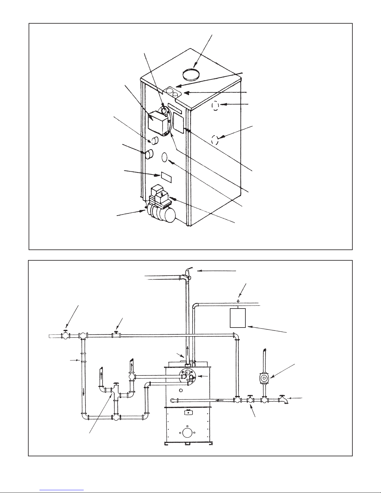
2) Install the boiler piping. For location of piping refer to the Installation Drawing.
DANGER: Boilers with tankless coils must be piped in accordance with the piping diagram
including installation of a tempering or mixing valve. Domestic hot water temperatures
exceeding 125°F will cause severe burns instantly or death by scalding.
WARNING: Relief valve discharges and drain valve piping must be piped to a safe place of
discharge.
NOTICE: S Series Boilers are provided with a built-in air scoop feature. This feature allows
quiet, air free operation of the hot water system by eliminating air pockets without installa tion of air scoops. The supply line tapping in the top of the boiler extends approximately 1
inch below the top of the boiler, allowing only air-free water to enter the heating system
supply. Any air trapped in the top of the boiler is purged through the 3/4” vent tapping.
The 3/4” vent tapping should be connected to an automatic float vent, a manual vent or
piped to a conventional expansion tank. See Appendix B for illustration.
3) Packaged boilers are shipped with the burner, aquastat and circulator installed and wired at
the factory. See the Basic Wiring Diagram for wiring schematic. See component manufac turer’s manual for wiring instructions.
4) An expansion tank, not provided, must be matched to the system and installed in accor dance with the manufacturer’s instructions. Do not undersize the expansion tank. An
automatic feed and pressure reducing valve, not provided, should be installed in the water
inlet line to keep the entire system from falling below the pressure setting of the valve (
about 12 psi) See the feed valve suppliers instructions for maximum allowed water supply
pressure and requirements for pressure reducers. For piping and wiring of other system
components see the manufacturer’s installation manuals.
5) The tank-less water heater may be piped as shown in the Installation Drawing. A mixing
4
Page 7

valve (tempering valve), not supplied, must be used to reduce the water temperature at
kitchen or bathroom taps. High temperature water for a dishwasher may be obtained by
piping as shown in the Installation Drawing. The nuts that secure the tank-less coil flange
should be tightened before the boiler is filled with water, after initial firing and once a year
during the annual maintenance.
CAUTION: Deterioration due to coil gasket leaks will void the warranty.
6) Connect boiler flue outlet to chimney using galvanized smoke pipe. Use only high quality
lock seam smoke pipe. The flue pipe should be pitched upward at least 1/4" per foot of run.
Refer to the boiler specifications for proper size flue pipe for your model boiler. Use only
elbows and straight sections. Tees may be used in a straight section in conjunction with a
barometric draft regulator however they must not be used for a 90° turn. Each joint should
be securely fastened with sheet metal screws. The flue pipe must not be inserted beyond
the inside wall of the chimney. Install barometric draft regulator in the horizontal or vertical
section of the flue pipe. The draft regulator should be installed in accordance with the
manufacturer’s instructions. Set the draft to in the stack as specified in the boiler specifica tions and on the Installer/Serviceman Label on the boiler jacket. The flue gas exit of the
venting system should be at designed with clearances in accordance with NFPA 31. A
chimney must be at least 3 feet above the highest point where it passes through the roof
and at least 2 feet higher than any portion of a building within 10 feet of the venting system.
The horizontal length of a chimney connector should not exceed 10 feet unless a draft
booster is used. Where the possibility of down drafts exist, install a listed vent cap.
WARNING: Installation and venting with improper materials or methods may result in
serious injury or death due to asphyxiation from poisonous gases such as carbon
monoxide. A carbon monoxide detector should be installed per the manufacturer’s
instructions.
7) The boiler room must be well ventilated to allow sufficient make-up air to support combus tion. Lack of adequate combustion air may result in erratic operation of the burner, noisy
combustion or fuel odors. Remember your need for outside air will be greatly increased if
you have a vented dryer in the basement or other venting fans in the home. Boilers located
in confined spaces shall be provided with two permanent openings, one near the top and
one near the bottom of the enclosure. Each opening shall have a free area of not less than
one square inch per 1000 BTU per hour input rating of the boiler, freely communicating with
interior areas having adequate infiltration from the outside.
8) Fill boiler and system with water. Be sure entire system has been purged of air and the
desired pressure is obtained. Leak-check the boiler and piping system by turning off the
make-up water supply and observing the boiler pressure gage. A loss of pressure indicates
a system leak that must be repaired prior to operating the boiler.
9) Remove the nozzle line assembly and check that the correct nozzle is installed for the
desired firing rate. Check that burner settings are correct for the nozzle that is installed.
See the Installer/Serviceman Label.
10) Connect burner to oil supply. Refer to fuel unit manufacturer literature for piping, connec tions, lift and tank installation. If such information is unavailable use the following guide
lines.
5
Page 8

FUEL UNITS/FUEL LINES
Fuel supply "level with" or "above" burner: A single stage fuel unit connected to the fuel sup-
ply with a single supply line is the most common type of installation for these conditions. Manual
venting of the fuel unit is usually required on initial start-up. Failure to vent air could result in an
air lock/oil starvation condition. (One pipe)
Fuel supply below the level of burner:
Use a single stage fuel unit in lift conditions of up to 10
ft., and a two stage fuel unit when the lift exceeds 10 ft. Both conditions require the use of a
return line which purges the fuel unit of air returning it to the fuel tank. The "by-pass" plug must
be inserted into the fuel unit when installing a return line. (Two pipe)
Fuel line installation:
Continuous lengths of heavy wall copper tubing are recommended and
should be installed under the floor when possible. Always use flare fittings. Always install fittings
in accessible locations. Never use teflon tape on any fuel fitting. Use of teflon will void any warranty. Fuel lines should not run against the appliance or the ceiling joists.
Fuel line valve and filter:
Install two high quality shutoff valves in accessible locations on the
oil supply line. Locate one close to the tank and the other close to the burner ahead of the filter.
Some filters come with built-in shutoff valves. Install a generous capacity filter inside the building
between the fuel tank shutoff valve and the burner locating both the filter and the valve close to
the burner for ease of servicing.
CAUTION: All oil feed lines to burners must be air tight. Use only flare fittings when assembling
oil lines since the slightest air leak, caused by loose fittings, bad gaskets or any other reason,
can cause a foaming oil stream which will cause any of the following conditions:
a) Intermittent firing, causing safety shutdown
b) Poor starts
c) Smokey starts
d) Continual sooting of boiler and burner parts including the cad cell
e) Reduced firing rate, inefficient operation and erratic fire pattern
f) A dangerous combustion condition, allowing the firebox to fill with a lean mixture (too
much air in the oil stream) which could cause a delay in ignition of the fuel mixture until
the danger point has been reached.
Suction Vacuum Test. A fuel pump suction vacuum test should be performed. See the fuel
pump manufacturers literature for details. The suction vacuum must be limited to ensure that
there is adequate pump lift. This problem becomes proportionately larger with underground
tanks. If the following procedures are followed, burner related problems will be minimized:
a) Connect vacuum gauge to oil pump. Suction vacuum must not exceed 10 inches of mercury
for single stage pumps and 15 inches for two stage pumps. It is preferable to stay below
these limitations.
b) When the suction line is tight and properly installed the pump will hold its vacuum for a
minimum of 60 minutes after shutdown.
c) Installation of a check valve in the suction line of a two pipe system is advisable under all
circumstances. Be sure the check valve fittings are airtight.
6
Page 9

11) Connect the electric supply to the boiler as indicated on the wiring diagram. The wiring
must be installed in accordance with the National Electrical Code and any other state and
local codes and the following requirements.
a) Internal wiring is completed at the factory on packaged boilers. External wiring must con
form with the National Electric Code and local codes.
b) Field connections should be protected with a 15 amp fuse.
c) A separate, fused disconnect switch should be installed and located near the unit so that
power can be shut-off for servicing, unless already equipped.
d) Install the room thermostat (not provided) on an inside wall away from cold drafts, windows
or heat from fireplaces, appliances or sunlight. Set the heat anticipator in accordance with
the manufacturer’s instructions. Connect the thermostat leads to the “TT” terminals on the
circulator control.
C. Operational Sequence
1) S Boilers equipped with tankless coil are equipped with a combination aquastat control
which has high and low limits to be set at 180° F and 160° F respectively by the installer.
These settings are nominal and may be adjusted for the particular installation conditions.
A 20° F difference between high and low limit is recommended. The control prioritizes
domestic hot water heating as explained below.
a. When room temperature falls below thermostat setting, thermostat calls for heat starting
the burner and circulating pump. The burner and pump continue to operate until room
heating requirements are satisfied (thermostat setting is reached), or until boiler water
temperature reaches the high limit control temperature setting. If the high limit control
temperature setting is reached, the burner shuts off and the circulating pump continues
to operate until the room heating requirements are satisfied. If the thermostat continues
to call for heat after the boiler water temperature has dropped to approximately 10
degrees below the temperature setting of the high limit control, the oil burner will start
again and the circulating pump will continue to run.
b. The boiler water temperature is normally maintained at 160°F around the tankless coil by
the operating control so that an abundance of hot water is available. If the boiler water
temperature should fall approximately 10 °F below the operating control low limit setting,
the oil burner will be started again by the control (and the circulating pump will be pre
vented from operating) until the operating control setting is satisfied. The operating con trol has an adjustable low limit differential setting. The low limit differential setting deter mines how high the boiler temperature must rise before the burner turns off and or the
circulator comes on if the thermostat calls for heat. The differential is measured from
10°F below the low limit. See control manufacturer’s literature included in the data pack age for detailed wiring, operating and safety instructions.
c. Adjusting the low limit differential to higher values will provide priority to heating domestic
hot water over a greater range of boiler temperature. (Maximum of approximately 25°F
differential measured from 10°F below the low limit setting.)
7
Page 10

2) S boilers not equipped with a tankless coil are may be provided with a high limit aquastat
control which should be set at 180°F by the installer. This setting is nominal and may be
adjusted for the particular installation conditions.
a. When room temperature falls below thermostat setting, thermostat calls for heat starting
the burner and circulating pump. The burner and pump continue to operate until room
heating requirements are satisfied (thermostat setting is reached), or until boiler water
temperature reaches the high limit control temperature setting. If the high limit control
temperature setting is reached, the burner shuts off and the circulating pump continues
to operate until the room heating requirements are satisfied. If the thermostat continues
to call for heat after the boiler water temperature has dropped to approximately 15
degrees below the temperature setting of the high limit control, the oil burner will start
again and the circulating pump will continue to run.
b. The boiler water temperature need not be maintained at a160°F low limit setting since
there is no domestic hot water load to protect. See control manufacturers literature
included in the data package for detailed wiring, operating and safety instructions.
c. Boilers without Tankless Coils may be equipped with a combination aquastat that has a
high and low limit setting. The high limit control is set at 180°F and the low limit is set
based on the application. If the boiler is used with an indirect hot water heater for
domestic hot water, the low limit is set at 160°F to support the operation of the indirect
hot water heater. If the an indirect hot water heater is not used, the low limit may be set
between 120°F and 140°F to provide protection against condensation in the boiler. The
settings are nominal and many be adjusted for the particular installation conditions.
3) A cadmium sulfide flame scanner (cad cell) and relay are provided with the oil burner. The
cad cell will stop the oil burner within a predetermined number of seconds if the fuel fails to
ignite or if the flame goes out during operation. The oil burner will remain off until the red
reset button on the relay has been pushed. Reset must never be pressed more than once
during a single flame failure.
D. Start-Up and Check-Out Procedure
CAUTION : Only a trained, experienced serviceman should attempt the checkout procedure outlined below. You should read to the burner manual provided with this manual for specific instructions and set points.
1) Confirm that electrical power to the boiler is off. The fuel tank must be filled with No. 2
heating oil. Low Sulfur fuel is preferred.
2) Check electrode settings, nozzle size and air setting. Electrode settings are shown in the
burner manual provided along with this manual. Burner settings are listed on the Service
Man’s Label attached to the boiler and on the Specifications provided along with this
manual.
3) Set thermostats substantially above room temperature.
4) Open all shut-off valves in the oil supply line to the burner.
8
Page 11

5) Install pressure gauge in the port provided on the oil pump. Attach a length of 1/4" O.D.
clear plastic tubing to the end of the bleed plug.
6) Turn on power to the boiler. If burner does not start immediately reset manual overload
switches and control. See control manual for reset instructions.
7) On one pipe systems bleed the oil pump as soon as burner motor starts. To bleed the pump,
loosen plug while holding an empty container under the tubing installed in step 6 to catch all
of the expelled oil. Bleed for at least 15 seconds after the oil stream is free of all air. If air is
still evident in the bleed line you must check the oil lines, all fittings, filters and any other
connections for tightness. Kinks in the oil lines will create undue high vacuum therefore they
must be eliminated. When you are sure all air has been eliminated then close the bleed
valve. Ignition should be instantaneous following the closing of this valve. If it is not, proceed
to the trouble shooting guide to determine why the oil did not ignite.
8) Be sure the oil pump discharge pressure is adjusted to the pressure listed on the Installer/
Service Man Label. If it is not, refer to the burner manufacturer's instruction sheet for
pressure adjustment procedure.
FINAL ADJUSTMENTS OF THE BURNER MUST BE MADE USING PROPER COMBUS
-
TION TEST EQUIPMENT. Combustion test equipment required for proper burner adjustment:
a) CO2 Analyzer
b) Draft Gauge
c) Oil Pressure Gauge 0-200 PSI
d) Stack Thermometer
e) Smoke Test Gun
f) Vacuum Gauge 0-30 in. of Hg
Notice: Read the burner manufacturer’s instructions supplied with this manual to set combustion. The burner instructions contain special instructions that may apply to the model supplied
with your boiler including how special features may affect the set-up procedure.
10) Burner Adjustments. Allow the burner to operate steadily for 5 to15 minutes. Check burner
settings shown on the Installer/Service Man Label and make the following adjustments.
a. Punch or drill a 1/4" hole in the flue pipe between the boiler and the barometric draft
regulator. All test readings should be taken from this point.
b. Take a draft reading from the flue pipe sampling hole. Adjust the draft in the stack, using
the barometric draft regulator, to the value shown on the Installer/Serviceman Label. In
tall chimneys a second draft regulator may be required in the flue pipe to regulate draft
under high draft conditions.
c. Remove the draft port plug over the fire and take a draft reading from the draft port.
Compare the readings with those on the INSTALLER/SERVICEMAN label. Refer to the
trouble shooting procedure if the draft over the fire reading is not correct. Reinstall the
draft port plug after all readings have been taken.
9
Page 12

d. Follow the burner manufacturer’s instructions to adjust the air supply until a trace of
smoke is recorded. At the trace of smoke level, measure the CO2. This is the reference
point for all further adjustments.
e. Increase the air supply to reduce the CO2 about 1 ? % to 2% from the reference point.
A zero smoke reading should result. If this adjustment can not be obtained, refer to the
Trouble Shooting section of this manual.
f. When combustion is set, follow the burner manufacturer’s instructions to lock or tighten
adjustment mechanisms as required.
11) Check operation of the cad cell relay by removing one cad cell wire from external terminal
during the flame cycle. The relay should cut the burner off in approximately 15 sec.
E. Servicing the Boiler/Burner Unit:
1) Burner Components: If replacement of burner parts is necessary, always use parts
recommended by the manufacturer. Specify part number and description when ordering.
2) Electrode settings are important for reliable ignition of the oil. Check to be sure the settings
are in accordance with the instructions provided in the burner manual.
3) Nozzles: The nozzle specifications listed in the manual are the result of years of exhaustive
engineering testing. Use extreme care in handling nozzles to avoid scratches or dirt that
could cause leaks or affect the oil spray pattern.
CAUTION: Any nozzle replacement should be of the exact type as listed in the specifications.
4) Fan and blower housing should be kept clean of dirt and lint. If heating unit is located near
an unvented dryer, special care must be taken so that lint does not clog the burner air inlets.
5) Replace the oil filter cartridge annually.
6) Check all water connections and plugs for evidence of leaks. Check for leaks by shutting
the make-up water supply valve. If boiler pressure decreases, it is evidence of a leak which
must be repaired.
7) Cleaning the Boiler: Cleaning should be done only by a trained, experienced serviceman.
DANGER: Before cleaning turn off all power to the boiler. Failure to turn off power could result
in firing the boiler when it is open.
A) Remove the flue pipe, jacket top and flue cover.
B) Remove baffles from the units and clean them. Brush all tubes with a #2 soft flue brush.
Use a boiler vacuum to collect any residue.
F) Inspect the burner head. Remove any accumulation on the burner. Inspect and follow
burner manufacturer’s recommendations for cleaning and maintenance.
10
Page 13

G) Check all refractory and gaskets for resilience and continuity. Replace damaged parts
prior to re-assembling the unit.
H) Reassemble the boiler.
8) Replacing the combustion chamber. In the event that the combustion chamber is replaced,
follow these instructions.
A) Turn off power to the boiler and burner and shut off the oil supply to the burner.
B) Remove the burner assembly from the base.
C) Loosen the jacket at all sides.
D) Remove the four bolts at the corners of the boiler that secure the heat exchanger to the
base.
E) Position bumper jacks at opposite corners of the lower tube sheet of the heat exchanger
or use a come along on a lifter rig located at the top of the boiler through the flue box
hole. A lifting lug is located just inside the flue box.
F) Raise the boiler about one inch or enough to slide the base out the front. The pipes
should flex enough to raise the boiler heat exchanger.
G) Remove the soft chamber and replace. Replace the spacer block under the chamber if it
is deteriorated.
H) Reinstall the firebox and reassemble the boiler.
I) Check boiler for proper operation.
Alternate chamber replacement procedure.
A) Turn off power to the boiler and burner and shut off the oil supply to the burner.
B) Remove the burner assembly from the base.
C) Remove the burner mounting cover from the base. Using a utility knife cut around the
flanged portion of the top of the chamber that is clamped between the boiler heat
exchanger and the base. Break up and remove the remaining portion of the chamber.
D) Using a utility knife, carefully trim the top flange of the new chamber to fit inside of the
flange area.
E) Lift the new chamber into the flange area creating a seal and support the new base with
the spacer block.
F) Reassemble the boiler.
G) Check for proper boiler operation.
11
Page 14

Troubleshooting Guide
TROUBLE: BURNER DOES NOT START
SOURCE PROCEDURE CAUSE REMEDY
Thermostat Check thermostat settings Thermostat set too low. Turn thermostat up.
Thermostat on “off or “cool”. Switch to heat.
Open thermostat wires. Repair or replace wires.
Loose thermostat connectors. Tighten connection.
Faulty thermostat. Replace thermostat.
Thermostat not level. Level thermostat.
Circuit Check burner motor overload Burner motor tripped on Push reset button.
Overloads switch overload.
Check primary control safety Primary tripped on safety. Reset safety switch.
switch.
Power Check furnace disconnect Switch open. Close switch.
switch and main disconnect
switch. Tripped breaker or blown fuse. Reset breaker or replace fuse.
Cad Cell Jump the FF terminals on Open cad cell wires. Repair or replace wires.
primary control. If the
burner starts, fault is in Dirty cell face. Clean face.
detector circuit. Faulty cad cell. Replace cad cell.
Primary Check for line voltage between Limit control switch open. Check limit setting (200˚).
Control the black and white leads. No
voltage indicates no power to Jump terminals - if burner
the control. starts replace control.
Open circuit between limit Repair circuit.
control and disconnect switch.
Low line voltage or power Call utility company.
failure.
Check for line voltage between Defective control. Replace control.
orange and white leads. No
voltage indicates a faulty control.
Burner Check for voltage at the black Pump seized. Turn off power to burner.
and white leads to the burner Blower wheel binding. Rotate blower by hand.
motor. Voltage indicates Check for excessive drag.
power to motor and a fault Replace fuel unit or blower
in the burner. wheel.
Burner motor defective. Replace burner motor.
A-1
Page 15

TROUBLE: BURNER STARTS BUT DOES NOT ESTABLISH FLAME
SOURCE PROCEDURE CAUSES REMEDY
Oil Check tank for oil. Empty tank. Fill tank.
Supply Check for water in oil tank Water in oil tank. Strip tank of water exceeding
using a dip stick coated 2" in depth.
with litmus paste.
Listen for pump whine. Fuel supply valve closed. Open valve.
Oil Line Open pump bleed port and Air leak in fuel system. Repair leak. Using only
and Filter start burner. Milky oil or no flared fittings. Do not use
oil indicates loss of prime. Teflon tape on oil fittings.
Listen for pump whine. Oil filter plugged. Replace filter cartridge.
Plugged pump strainer. Clean strainer.
Restriction in oil line. Repair oil line.
Oil Pump Install pressure gauge in port Pump worn - low pressure. Replace pump.
of fuel pump. Pressure should Motor overloads.
be 140 psi. Coupling worn or broken. Replace coupling.
Pump discharge pressure Set pressure at 140 psi.
set too low.
Ignition Connect transformer leads to No spark or weak spark. Replace transformer.
Transformer line voltage. Listen for spark.
Check that transformer Line voltage below 102V. Call utility company.
terminals are not arcing with
buss bars. Check that trans-
former is properly grounded.
Ignition Remove and inspect draw Carboned and shorted Clean electrodes.
Electrodes assembly. electrodes.
Eroded electrode tips. Dress up tips and reset
Incorrect electrode settings. electrodes.
Cracked porcelain insulators. Replace electrodes.
Nozzle Inspect nozzle for plugged Plugged orifice or distributor. Replace nozzle with nozzle
orifice and distributor slots. Plugged nozzle strainer. specified on burner housing.
Poor spray pattern.
Inspect nozzle for correct Incorrect nozzle installed. Install correct nozzle.
size and specifications.
Combustion Check air shutter and air band. Air shutter open too far. Decrease air shutter setting.
Air
Adjustments Air band open too far. Decrease air band opening.
TROUBLE: HGH NET STACK TEMPERATURES
SOURCE PROCEDURE CAUSES REMEDY
Nozzle Check pump pressure with Nozzle overfiring due to high Reduce pump pressure to
pump gauge. pump pressure. 140 psi.
Heat Check heat exchanger surfaces Heat exchanger fouled. Clean heat exchanger.
Exchanger for soot or scale fouling.
A-2
Page 16

TROUBLE: BURNER FIRES, BUT THEN LOSES FLAME
SOURCE PROCEDURE CAUSES REMEDY
Poor Fire Inspect flame for stability. Unbalanced fire. Replace nozzle with specified
nozzle.
Excessive draft. Reduce draft setting.
Insufficient draft. Increase draft.
Too little combustion air. Increase combustion air.
Oil Supply If burner loses flame prior to Air leak in fuel system. Repair leak - use only flare
the primary control locking fittings.
out, fault is in fuel system. Water in oil tank. Strip tank of water exceeding
2” in depth.
Fuel supply valve closed. Open valve.
Restriction in oil line. Clear oil line restriction.
Plugged fuel filter. Replace filter cartridge.
Plugged pump strainer. Clean strainer.
Cold oil. Use #1 heating oil.
Combustion Reduce combustion air supply. Too much combustion air. Close air band and air to
2
Air raise CO
Pump Install pressure gauge in gauge Pump discharge pressure Set pressure at 140 psi.
port of fuel pump. Pressure incorrectly set.
should be 140 psi. Coupling worn or broken. Replace coupling.
Pump worn - low pressure Replace pump.
motor overloads.
.
Excessive Take a draft reading. Draft Incorrect draft setting. Reduce draft setting. Install
Draft should be -.05”-.06” W.C. in second draft regulator if
stack. necessary.
Poor Flue Insert C02probe into heat Leak in flue system. Sample C02in heat exchanger.
Gas Sample exchanger tube. If reading is
greater by 1/2% or more, sample Seal flue system leak.
was being diluted near flue box.
Testing Using a chemical absorption Weak fluid. Replace fluid in testing
Method type device, let instrument set device.
after a test before venting. If
CO2 reading increases 1/2%
fluid is weak.
Nozzle Inspect nozzle for plugged Plugged orifice or distributor. Replace nozzle with specified
orifice and distributor slots. Plugged nozzle strainer. nozzle.
Poor spray pattern.
TROUBLE: INSUFFICIENT DOMESTIC HOT WATER
SOURCE PROCEDURE CAUSES REMEDY
Tankless Coil Analyze capacity vs. usage. Insufficient coil capacity. Install larger coil.
Operating Check operating control Setting too low. Set operating control to 180˚ F.
Control setting.
Heat Inspect coils for fouled surfaces Flow restriction. Remove restriction.
Exchanger and/or flow restrictions. Fouled surfaces on heat Clean heat exchanger surfaces.
exchanger.
A-3
Page 17

TROUBLE: BURNER FIRES BUT PULSATES
SOURCE PROCEDURE CAUSES REMEDY
Draft Take a draft reading. Draft Down drafts. Install vent cap.
should be -.05” -.06: W.C. in Insufficient draft. Increase draft setting.
the stack. Excessive draft. Reduce draft settings, install
second draft regulator if
necessary.
Draft Inspect draft regulator for Improper installation. Move draft regular to correct
Regulator correct location on flue system. location.
Combustion Inspect installation for com- Improper installation. Provide openings that freely
Air bustion air provisions. communicate with outside.
Open air band wide and take Improper adjustment. Adjust CO2level - start with
CO2reading. air band wide open.
Oil Supply Bleed pump; inspect for air Air leak in fuel system. Repair leak - use only flare
leaks or water contamination. Compression fittings. joints.
Water in oil tank. Strip tank of water exceeding
2” in depth.
Pump Install pressure gauge in gauge Pump discharge pressure Set pressure at 140 psi.
Pressure port of fuel pump. Pressure incorrectly set.
should be 140 psi. Coupling worn or broken. Replace coupling.
Pump worn - low pressure Replace pump.
motor overloads.
Nozzle Inspect nozzle for plugged Plugged orifice or distributor. Replace nozzle with nozzle
orifice and distributor slots. Plugged nozzle strainer. specified on burner housing.
Poor spray pattern.
Heat Take draft reading at flue box Plugged heat exchanger. Clean out heat exchanger.
Exchange rand read draft over the fire.
Restrictions Difference should not exceed
-.03”.
TROUBLE: BURNER FIRES, BUT THEN FAILS ON SAFETY
SOURCE PROCEDURE CAUSES REMEDY
Cad Cell Check cad cell with ohmeter. Faulty or dirty cad cell. Clean or replace cad cell.
If more than 2000 ohms, cad
cell is defective or dirty.
Primary After burner fires open cad cell Faulty primary control. Replace primary control.
Control circuit if flame looks OK. If
burner continues to operate,
fault is in primary control.
Poor Fire Inspect flame for shape and Unbalanced fire Replace nozzle with
uniformity or color specified nozzle.
Excessive draft. Reduce draft setting.
Insufficient draft. Increase draft.
Too little combustion air. Increase combustion air.
Heat Take draft reading at flue box Plugged heat exchanger. Clean out heat exchanger.
Exchanger and read draft over the fire.
Restriction Difference should not exceed
-.03”.
Burner Burner motor trips on overload. Line voltage below 102V Call utility company.
Motor Turn off power and rotate Faulty motor. Replace motor.
blower by hand to check for Pump or blower overloading Replace blower or pump.
excessive drag. motor.
A-4
Page 18

TROUBLE: INSUFFICIENT HEAT
SOURCE PROCEDURE CAUSES REMEDY
Circulator Check if circulator is opera- Coupling worn or broken. Replace coupling.
tional. Pump binding. Replace pump.
Circulator motor burned out. Replace circulator motor.
Wiring from operating Repair wiring.
control defective.
Operating control defective. Repair or replace operating
control.
Check if circulator is correct Circulator too small. Replace with proper circulator.
size.
Check if circulator is up to Circulator defective. Repair circulator.
speed; check if voltage to
circulator is sufficient. Insufficient voltage. Call utility company.
Thermostat Check thermostat settings. Settings too low. Increase setting.
Check thermostat location. Bad location due to heat Move thermostat to a better
build up. location.
Check thermostat calibration. Out of calibration. Recalibrate.
Flow Valve Check flow valve for sticking Flow valve not opening fully. Clean or replace flow valve.
in partially closed position.
Radiation Check for air in radiators. Radiators airbound. Bleed radiators.
Check to see if radiators are Radiators inadequate. Install adequate radiation.
sized properly.
Boiler Determine structure heat load. Boiler too small. Additional heating capacity
required.
Piping Check to see if piping is sized Piping inadequate. Install adequate piping.
properly.
Tankless Check usage of domestic Demand too large. Install flow regulator.
Coil hot water. Additional boiler capacity
required.
Heat Check heat exchanger for soot Insufficient heat transfer. Clean heat exchanger.
Exchanger or scale accumulation.
Burner Check pump pressure with Insufficient pump pressure. Increase pressure to 140 psi.
pressure gauge.
Nozzle Check nozzle for size and Wrong nozzle installed. Install specified nozzle.
spray angle.
Check nozzle for plugged Nozzle underfiring due to Replace nozzle.
orifice, scored surface. defective nozzle.
A-5
Page 19

TROUBLE: TOO MUCH HEAT
SOURCE PROCEDURE CAUSES REMEDY
Circulator Check to see if operating Circulator does not stop Repair operating control.
control is working properly. running.
Thermostat Check thermostat settings and Thermostat set too high. Reset thermostat.
calibration. Thermostat defective. Replace thermostat.
Thermostat out of calibration. Recalibrate.
Flow Check to see if flow valve is Flow valve dirty and stuck. Clean flow valve.
Valve operating properly. Flow valve defective. Replace flow valve.
A-6
Page 20
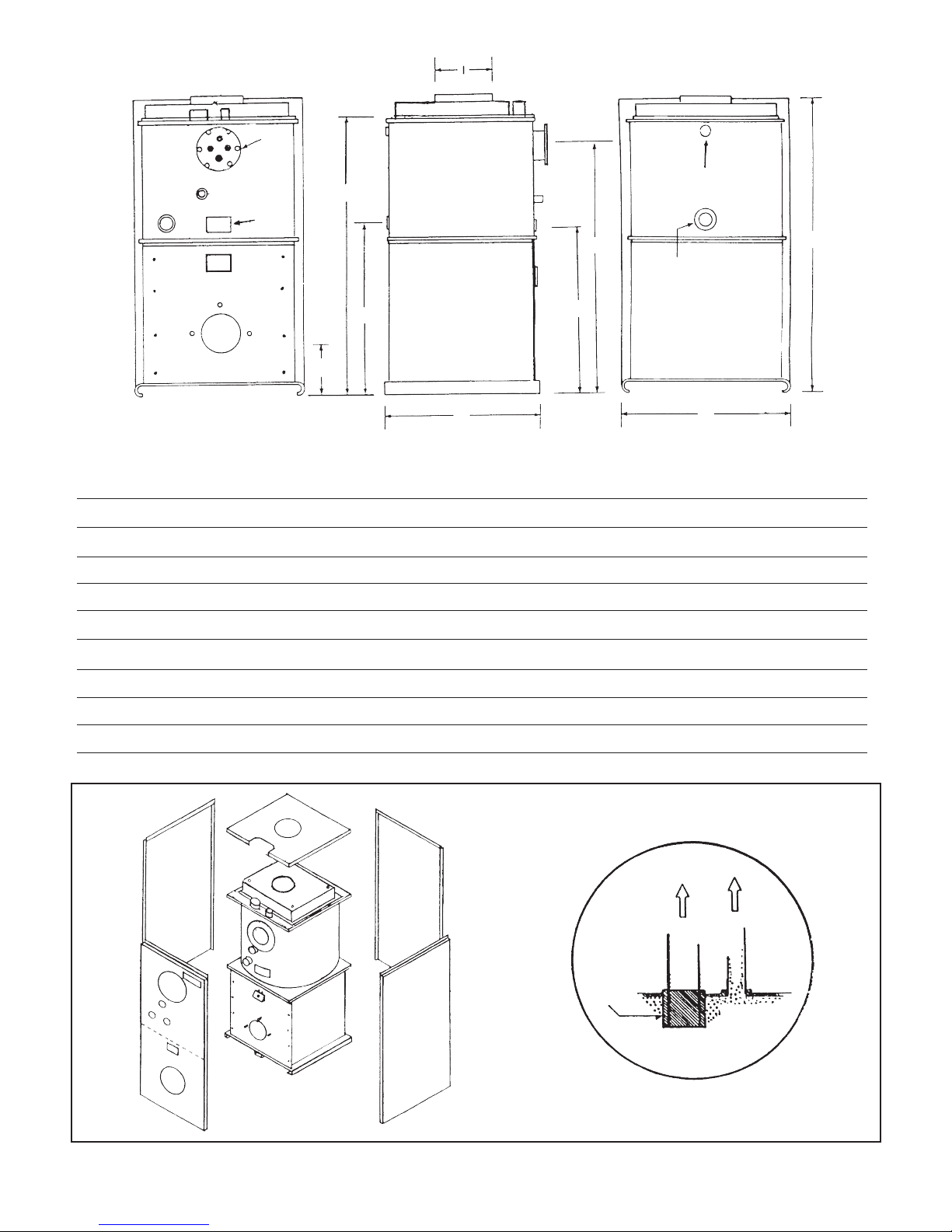
RETURN
COIL
&
ALT
GAUGE
ASME
TAG
BOILER TUBE SECTION
G
D
RELIEF VALVE
A
HYDRONIC RETURN
CHAMBER SECTION
C
Figure 1
FRONT
F
H
S
Series Dimensions
A - Jacket Height 38
B - Jacket Width 21
C - Jacket Length 21
D Coil Height 31
E
BACK
B
1/2
1/4
1/4
1/2
E - Hydronic Return Height 22
F - Alt. Hydronic Return 22
G - Hydronic Supply Height 36
H - Burner Opening From Floor 8
3/4
I - Flue Pipe Diameter 6
Figure 2. Jacket Assembly
Appendix B
BUILT IN
AIR SCOOP
S
U
P
P
L
Y
T
O
V
E
N
T
BOILER WATER
Page 21

Specifications
MODELS S85 S100 S110 S125 S135 STR-85 STR-100 STR-110
IBR Firing Rate G.P.H. (Max.) .85 1.00 1.10 1.25 1.35 .85 1.00 1.10
IBR Input (BTU/HR) 119,000 140,000 154,000 175,00 189,000 119,000 140,000 154,000
IBR Heating Capacity (BTU/HR)* 100,000 117,000 129,000 148,000 159,000 101,000 121,000 133,000
IBR Net Rating (BTU/HR) 87,000 102,000 112,000 129,000 138,000 88,000 106,000 116,000
Chimney Size 8x8x15 8x8x15 8x8x15 8x8x815 8x8x15 8x8x15 8x8x15 8x8x15
Draft Over Fire (Negative) -.02 -.02 -.02 -.02 -.02 -.02 -.02 -.02
Water Content (Gal.) 16 15-1/2 15 14 14 15 14 14
Domestic Coil Capacity** gpm 3 or 5 3 or 5 3 or 5 3 or 5 3 or 5 3 or 5 3 or 5 3 or 5
A - Jacket Height 38-1/2" 38-1/2" 38-1/2" 38-1/2" 38-1/2" 38-1/2" 38-1/2" 38-1/2"
B - Jacket Width 21-1/4" 21-1/4" 21-1/4" 21-1/4" 21-1/4" 21-1/4" 21-1/4" 21-1/4"
C - Coil Supply Height 31-1/2" 31-1/2" 31-1/2" 31-1/2" 31-1/2" 31-1/2" 31-1/2" 31-1/2"
D - Hydronic Return Height 22" 22" 22" 22" 22" 22" 22" 22"
E - Jacket Length 21-1/4" 21-1/4" 21-1/4" 21-1/4" 21-1/4" 21-1/4" 21-1/4" 21-1/4"
F - Alt. Hydronic Return 22" 22" 22" 22" 22" 22" 22" 22"
G - Hydronic Supply Height 36" 36" 36" 36" 36" 36" 36" 36"
H - Flue Pipe Diameter 6" 6" 6" 6" 6" 6" 6" 6"
I - Relief Valve Height 33-1/2" 33-1/2" 33-1/2" 33-1/2" 33-1/2" 33-1/2" 33-1/2" 33-1/2"
Shipping Weight (Approx.) 320 325 330 345 350 330 360 360
Hydronic Supply Tapping 1-1/4" 1-1/4" 1-1/4" 1-1/4" 1-1/4" 1-1/4" 1-1/4" 1-1/4"
Hydronic Return Tappings 2-1-1/4" 2-1-1/4" 2-1-1/4" 2-1-1/4" 2-1-1/4" 2-1-1/4" 2-1-1/4" 2-1-1/4"
AFUE*** 84.3 84.2 84.0 84.6 84.0 85.2 85.4 85.1
•Based on D.O.E. Test Procedures
••Coil capacity based on 5 min. draw. 5 min. waiting period.
***AFUE with vent damper - S85-110 2.5% higher, S125-150 1.4% higher
Appendix C
Page 22
ALTITUDE GAUGE
AQUASTAT RELAY
ALTERNATE
LIMIT
HYDRONIC RETURN
FLUE OUTLET
HYDRONIC SUPPLY
AIR SCOOP VENT
RELIEF VALVE
ALTERNATE RETURN
INSPECTION PORT
HIGH SPEED
FLAME RETENTION
BURNER
GATE VALVE
CHECK
VALVE
DOMESTIC
COLD WATER
IN
WARM
WATER
PRESSURE RED.
VALVE
DOMESTIC HI
TEMP WATER
S
Series
SUPPLY
RATING DECAL
EXTENDED TANKLESS COIL
ASME TAG
PRIMARY CONTROL
FLO-CONTROL VALVE
AIR VENT
EXPANSION TANK
CIRCULATING
PUMP
TANKLESS
COIL
W/T&A
DRAIN
RETURN
TEMPERING
VALVE
Figure 3. Boiler Piping
GATE VALVE
Install Relief Valve in top tapping on rear of boiler.
Relief Valve discharge and drain valve piping should
be piped to a safe place of discharge.
Appendix D
Page 23
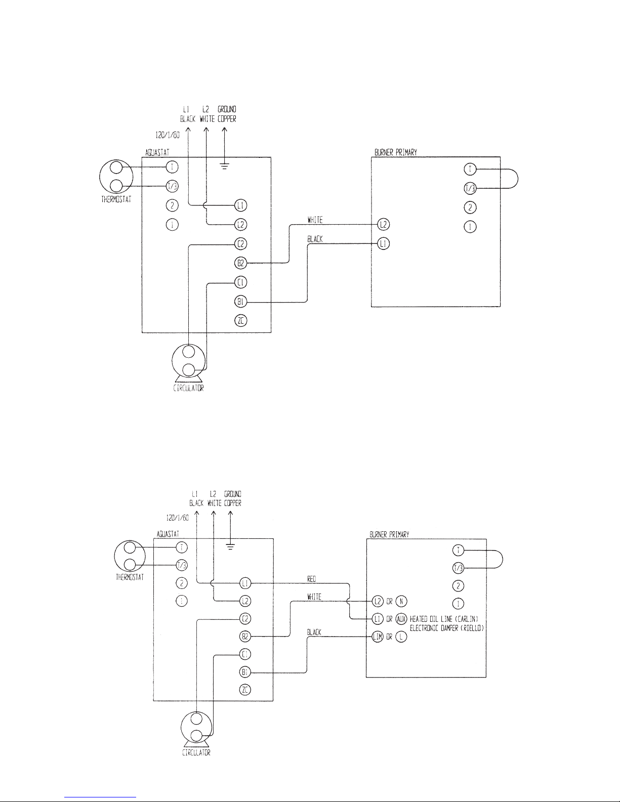
ELECTRICAL DIAGRAM FOR S SERIES BOILERS
TO CONNECT BURNER TO AQUASTAT
(APPLIES TO BECKETT CHIMNEY VENT BURNERS)
ELECTRICAL DIAGRAM FOR S SERIES BOILERS
TO CONNECT BURNER TO AQUASTAT
(APPLIES TO CARLIN CHIMNEY VENT AND RIELLO CHIMNEY VENT BURNERS)
Appendix E
Page 24

INSTALLER/SERVICEMAN
Model Number S-125 S-135
Burner Type Riello Riello
Burner Model F5 F5
Nozzle Type 1.00 60A 1.10 60A
Pump Pressure PSI 150 150
Head/Pin Position 2.5 3.5
Air Band N/A N/A
Air Shutter 4.5 4.5
Draft Over Fire -0.02" -0.02"
Draft In Stack -0.05" -0.05"
CO2Reading 10-11.5 10-11.5
Smoke Reading ZERO ZERO
________________________
________________________
________________________
________________________
________________________
________________________
________________________
________________________
________________________
________________________
INSTALLER/SERVICEMAN
Model Number S-125 S-135
Burner Type Carlin Carlin
Burner Model EZ-1 EZ-1
Nozzle Type 1.00 60A 1.10 60A
Pump Pressure PSI 140 140
Head/Pin Position 110-125 135-150
Air Band 1.25 1.35
Air Shutter N/A N/A
Draft Over Fire -0.02" -0.02"
Draft In Stack -0.05" -0.05"
CO2Reading 10-11.5 10-11.5
Smoke Reading ZERO ZERO
________________________
________________________
________________________
________________________
________________________
________________________
________________________
________________________
________________________
________________________
NOTICE
Above settings are approximate. Final adjustments to be made
with proper test equipment. Be sure all oil lines are air free and
the use of flare fittings is recommended. See installation/service
manual for detailed information.
INSTALLER/SERVICEMAN
Model Number S-125 S-135
Burner Type Beckett Beckett
Burner Model AFG AFG
Nozzle Type 1.00 80A 1.10 80A
Pump Pressure PSI 140 140
Head/Pin Position F-12 F-12
Air Band CLOSED 1
Air Shutter 10 10
Draft Over Fire -0.02" -0.02"
Draft In Stack -0.05" -0.05"
CO2Reading 10-11.5 10-11.5
Smoke Reading ZERO ZERO
________________________
________________________
________________________
________________________
________________________
________________________
________________________
________________________
________________________
________________________
NOTICE
Above settings are approximate. Final adjustments to be made
with proper test equipment. Be sure all oil lines are air free and
the use of flare fittings is recommended. See installation/service
manual for detailed information.
NOTICE
Above settings are approximate. Final adjustments to be made
with proper test equipment. Be sure all oil lines are air free and
the use of flare fittings is recommended. See installation/service
manual for detailed information.
Appendix F
Page 25

INSTALLER/SERVICEMAN
INSTALLER/SERVICEMAN
Model Number S-85
Burner Type Beckett Carlin Riello
Burner Model AFG* EZ-1 F5
Nozzle Type 0.65 80B 0.65 60A 0.65 60A
Pump Pressure PSI 140 140 150
Head/Pin Position F-3 85-100 1.5
Air Band CLOSED 0.85 N/A
Air Shutter 10 N/A 1.75
Draft Over Fire -0.02" -0.02" -0.02"
Draft In Stack -0.05" -0.05" -0.05"
CO2Reading 10-11.5 10-11.5 10-11.5
Smoke Reading ZERO ZERO ZERO
*With AFG use low firing rate baffle
Above settings are approximate. Final adjustments to be made
with proper test equipment. Be sure all oil lines are air free and
the use of flare fittings is recommended. See installation/service
manual for detailed information.
________________________
________________________
________________________
________________________
________________________
________________________
________________________
________________________
________________________
________________________
NOTICE
Model Number S-100
Burner Type Beckett Carlin Riello
Burner Model AFG EZ-1 F5
Nozzle Type 0.75 80B 0.75 60A 0.75 60A
Pump Pressure PSI 140 140 150
Head/Pin Position F-3 85-100 2.0
Air Band CLOSED 1.00 N/A
Air Shutter 8 N/A 4
Draft Over Fire -0.02" -0.02" -0.02"
Draft In Stack -0.05" -0.05" -0.05"
CO2Reading 10-11.5 10-11.5 10-11.5
Smoke Reading ZERO ZERO ZERO
Above settings are approximate. Final adjustments to be made
with proper test equipment. Be sure all oil lines are air free and
the use of flare fittings is recommended. See installation/service
manual for detailed information.
________________________
________________________
________________________
________________________
________________________
________________________
________________________
________________________
________________________
________________________
NOTICE
INSTALLER/SERVICEMAN
Model Number S-110
Burner Type Beckett Carlin Riello
Burner Model AFG EZ-1 F5
Nozzle Type .85 80B 0.85 60A 0.85 60A
Pump Pressure PSI 140 140 150
Head/Pin Position F-3 110-125 2.5
Air Band CLOSED 1.10 N/A
Air Shutter 10 N/A 4
Draft Over Fire -0.02" -0.02" -0.02"
Draft In Stack -0.05" -0.05" -0.05"
CO2Reading 10-11.5 10-11.5 10-11.5
Smoke Reading ZERO ZERO ZERO
Above settings are approximate. Final adjustments to be made
with proper test equipment. Be sure all oil lines are air free and
the use of flare fittings is recommended. See installation/service
manual for detailed information.
________________________
________________________
________________________
________________________
________________________
________________________
________________________
________________________
________________________
________________________
NOTICE
Appendix F
Page 26

STR Energy Star Product
INSTALLER/SERVICEMAN
Model Number STR-85
Burner Type Beckett Carlin Riello
Burner Model AFG* EZ-1 F5
Nozzle Type 0.65 80B 0.65 60A 0.65 60A
Pump Pressure PSI 140 140 150
Head/Pin Position F-3 85-100 1.5
Air Band CLOSED 0.85 N/A
Air Shutter 10 N/A 1.75
Draft Over Fire -0.02" -0.02" -0.02"
Draft In Stack -0.05" -0.05" -0.05"
CO2Reading 10-11.5 10-11.5 10-11.5
Smoke Reading ZERO ZERO ZERO
*With AFG use low firing rate baffle
Above settings are approximate. Final adjustments to be made
with proper test equipment. Be sure all oil lines are air free and
the use of flare fittings is recommended. See installation/service
manual for detailed information.
________________________
________________________
________________________
________________________
________________________
________________________
________________________
________________________
________________________
________________________
NOTICE
INSTALLER/SERVICEMAN
Model Number STR-100
Burner Type Beckett Carlin Riello
Burner Model AFG EZ-1 F5
Nozzle Type 0.75 80B 0.75 60A 0.75 60A
Pump Pressure PSI 140 140 150
Head/Pin Position F-3 85-100 2.0
Air Band CLOSED 1.00 N/A
Air Shutter 8 N/A 4
Draft Over Fire -0.02" -0.02" -0.02"
Draft In Stack -0.05" -0.05" -0.05"
CO2Reading 10-11.5 10-11.5 10-11.5
Smoke Reading ZERO ZERO ZERO
Above settings are approximate. Final adjustments to be made
with proper test equipment. Be sure all oil lines are air free and
the use of flare fittings is recommended. See installation/service
manual for detailed information.
________________________
________________________
________________________
________________________
________________________
________________________
________________________
________________________
________________________
________________________
NOTICE
INSTALLER/SERVICEMAN
Model Number STR-110
Burner Type Beckett Carlin Riello
Burner Model AFG EZ-1 F5
Nozzle Type .85 80B 0.85 60A 0.85 60A
Pump Pressure PSI 140 140 150
Head/Pin Position F-3 110-125 2.5
Air Band CLOSED 1.10 N/A
Air Shutter 10 N/A 4
Draft Over Fire -0.02" -0.02" -0.02"
Draft In Stack -0.05" -0.05" -0.05"
CO2Reading 10-11.5 10-11.5 10-11.5
Smoke Reading ZERO ZERO ZERO
Above settings are approximate. Final adjustments to be made
with proper test equipment. Be sure all oil lines are air free and
the use of flare fittings is recommended. See installation/service
manual for detailed information.
________________________
________________________
________________________
________________________
________________________
________________________
________________________
________________________
________________________
________________________
NOTICE
Appendix F
Page 27

PARTS LIST
(Designate boiler and burner model numbers on all orders.)
Item No. Description Part No.
1 Carlin EZ1 Burner 542210
2 Riello 5F Burner 6" Tube w.Primary 541167
3 Beckett AGF Burner 540545
4 Solid State Electronic Transformer 675981
5 F-3 Burner Head (S-85/110 AFG) 675400
6 F-12 Burner Head (S-125/150 AFG) 675420
7 3-1/2" Static Plate (All AFG) 675931
8 Low Firing Rate Baffle (S-85/AFG) 675920
9 Suntech Single-Stage Fuel Pump 675300
10 Suntech Two-Stage Fuel Pump (Optional) 675310
11 007 Circulator Pump 535030
12 Genisys Primary Control 553007
13 Aquasmart Control 552111
14 2N1 Sensor 552108
15 Relief Valve 3/4" (Male) 575020
16 Altitude Gauge 1/4"-2-1/2" Round 559560
17 Coil Gasket (TDR All) 481005
18 Blank Coil Plate with 3/4" Tapping (TDR) 229151
19 #35 Coil (TDR) w/Gasket - Cartoned 530243
20 #55 Coil (TDR) w/Gasket - Cartoned 530247
21 Replacement Soft Chamber Only 337350
22 Chamber Base Assembly (Complete with Metal Base) 221750
23 Chamber Base Front Only (Metal with Studs) 223080
24 Cast Iron Peep Door Assembly (with Test Plug) 815800
25 Spacer Block (Between Chamber & Base) 337352
26 Baffles (State Model & Amount) 229515
27 Nozzles Beckett AFG @ 140 PSI Pump Pressure
.65 - 80˚B (S-85) 680102
.75 - 80˚B (S-100) 680117
.85 - 80˚B (S-110) 680127
1.00 - 80˚A (S-125) 680146
1.10 - 80˚A (S-135) 680156
.65 - 80˚B (STR-85) 680102
.75 - 80˚B (STR-100) 680117
.85 - 80˚B (STR-110) 680127
Appendix G
Page 28
S Series
Service Set-Up Records
Initial Set Up
1 2 3 4
1. Date
2. Model Number
3. Firing Rate
4. Pump Pressure Set 140 PSI
5. CO
6. "O" Smoke
7. Gross Stack˚
8. Draft Over Fire
9. Replaced Filter Yes/No
10. Replaced Nozzle Yes/No
11. Clean Pump Filter Yes/No
12. Inspect Coil Gasket
13. Check for leaks @ plugs/fittings
14. *Brush Clean Flue Tub Passages
15. Vacuum Chamber/Flue Tubes
16. Clean Blower Wheel
17. Check/Set Electrodes
*Soft fiber chamber...Exercise care to avoid damage.
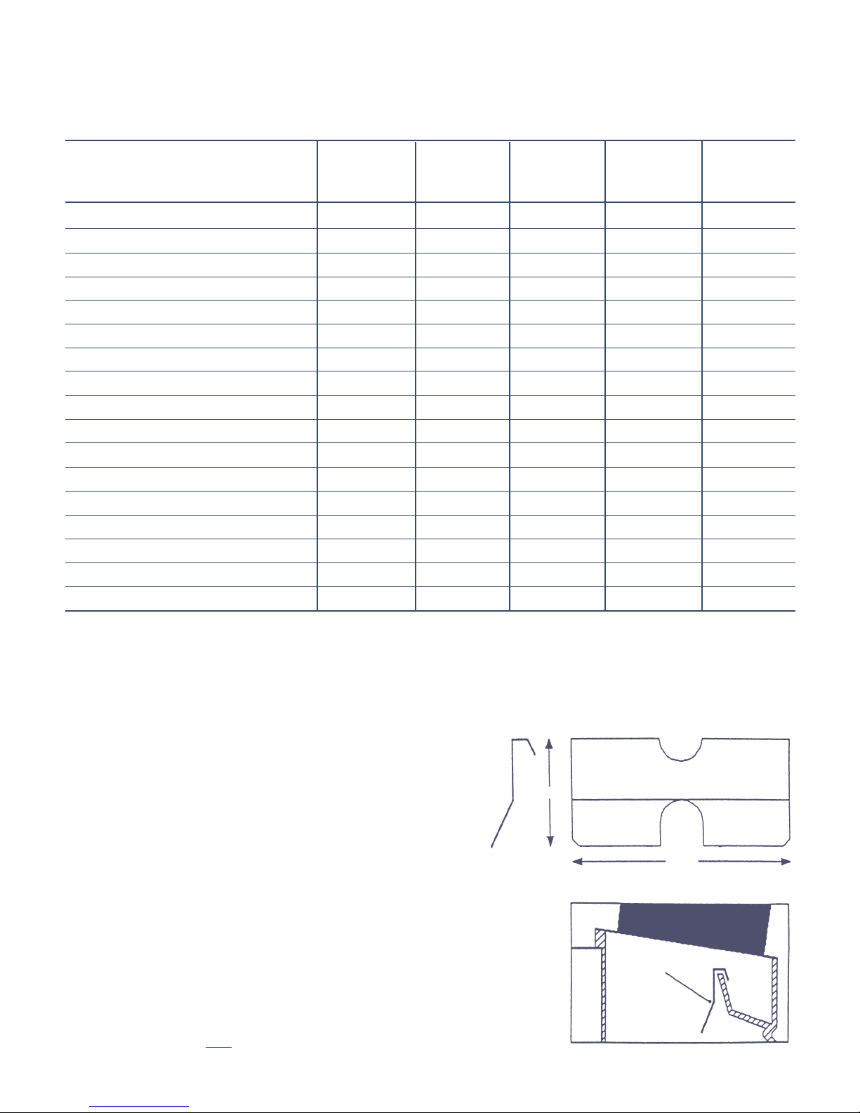
EXPLANATION OF LOW FIRING RATE BAFFLE
The Beckett low firing rate baffle is a small metal plate. It is
installed over the back of the blower wheel scroll, which is
visible when the transformer is swung back.
The low firing rate baffle is used to partially restrict the flow
of combustion air to the combustion head. When the baffle is
placed in the stream of air going from the blower wheel to the
head, it increases the load on the blower wheel. This reduces
the CFM and increases the operating pressure.
At the lower firing rates the combustion head has an easier
time controlling the reduced air supply. The result is better
starts and running characteristics. Flame stability at start-up
is improved due to higher blower operating pressure which
tends to dampen flame pulsations. It also means less sensitive air shutter adjustments.
Another advantage is that the inlet air controls must now be
opened more to overcome the added resistance of the baffle.
This means that the openings are less prone to restriction
due to buildup of dust, lint or pet hair.
The baffle is used only
MET-3937
8/14-500
on the model S-85.
1 3/4"
3 3/4"
figure 1
Low Firing Rate Baffle
figure 2
 Loading...