

Thermo Dynamics Solar Boiler SB32-9PV, Solar Boiler SB64-9PV, Solar Boiler Installation Manual
Solar BoilerS
By Thermo Dynamics Ltd.
Installation Manual for SB32-9PV, SB64-9PV, Systems
Fuel Prices are
always rising ...
So is the
1
2
3
S
U
cold water
supply
N
Congratulations on the purchase of your new Solar Boiler™ by Thermo
Dynamics Ltd. The Solar Boiler™ is the newest and most advanced concept in
residential solar water heating systems.
This manual outlines all the steps for a quick, easy, trouble-free installation.
Read the entire manual carefully before any installation attempt is made.
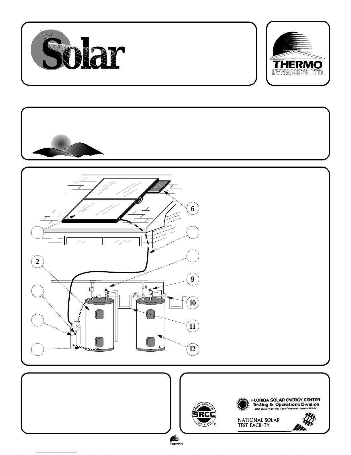
1. Micro-Flo® solar collectors
2. Solar storage tank
3. Temperature gauge (optional)
4. Solar Boiler™ Module
5. 3/4" Hard Copper Tube
6. Photovoltaic Module
7. LifeLine® tubing
8. Solar isolation and bypass valves
domestic hot
wat e r suppl y
6
7
8
9
4
5
WARNING:
- Installation shall be in accordance with the National Fire Code, and all local
codes.
- The approved heat transfer fluid is a mixture of 40% Propylene Glycol USP and
60% distilled water. The substitution of any other heat transfer fluid can cause
irreparable damage and create a health and safety hazard.
- The Solar Boiler™ module contains 3.75 litres, (1 USgallon), of heat transfer
fluid when full.
- The installation of the Solar Boiler™ should be inspected by a qualified
technician prior to start-up.
10
11
12
CERTIFICATION
The solar energy system described by this manual, when properly installed and maintained,
meets the minimum standards established by the SRCC, (Solar Rating & Certification
Corporation). This certification does not imply endorsement or warranty of this product by
SRCC.
9. Temperature - pressure relief valve
10. Mixing valve
11. Heat traps
12. Auxiliary water heater
Solar Boiler™ Installation Manual (OG-300), page 1 of 14IN.410.06.DEC/99
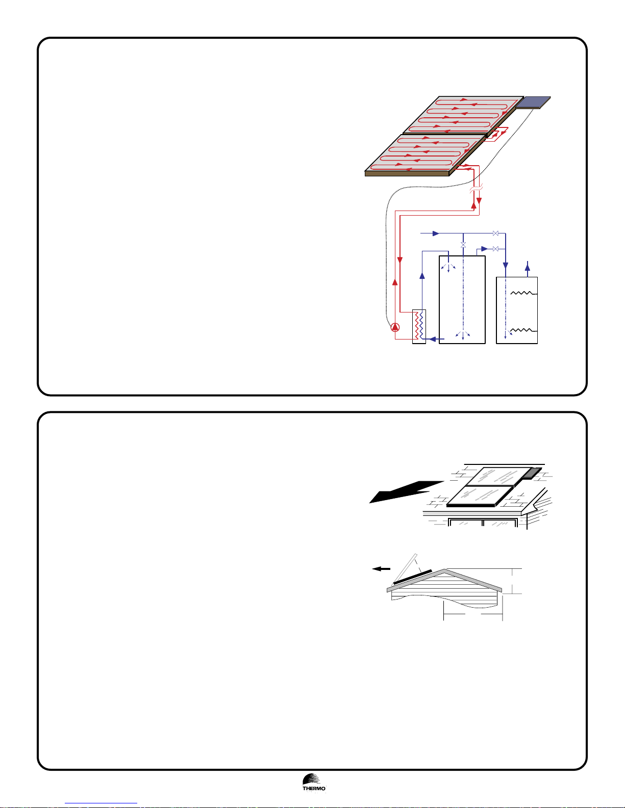
How the Solar Boiler™ works
• Solar collectors absorb sunlight and convert it to heat.
• When there is sufficient sunlight, the photovoltaic module produces
electricity and turns the pump.
• The pump circulates heat transfer fluid, (HTF), through the solar
collectors.
• Heat is transferred to the HTF in the solar collector.
• The HTF is returned to the heat exchanger in the Solar Boiler™
module.
• The heat is transferred to the water which circulates naturally to the
top of the solar storage tank.
• Solar heated water is stored in the solar storage tank until water is
drawn from the auxiliary tank (in this case an electric water heater).
• As hot water is drawn from the electric water heater it is replaced
with solar heated water.
• The electric heaters increase the temperature of the solar heated
water, if necessary.
• The electrical energy required to heat water is significantly less when
water is preheated by the solar water heater.
• In this manner, the solar water heater saves electrical energy.
S32 A
Solar Collector
S32B
Solar Collector
[Optional]
Cold Water IN
Ball valve #2
Ball valve #1
Ball valve #3
PV module
Wire - supplies 12 VDC
from PV module to
Solar Boiler™
Normal Operation
Ball valve #1 - Close
Ball valve #2 - Open
Ball valve #3 - Open
Hot Water OUT
NOTE: The Solar Boiler™ is designed to shut off when a temperature
of 180°F is attained in the solar storage tank.
The HTF is a 40/60 % by volume mixture of Propylene Glycol
USP and distilled water, and will provide freeze protection to 10°F (-24°C)
Solar Collector Installation
Micro-Flo® solar collectors are designed to work with the Solar
Boiler™ module and other Micro-Flo® systems.
Locate the solar collectors on the roof of your home that is oriented true
south or as close as possible. There are no major losses up to 45° east or
west of true south. If your orientation is not in this range, consider a
ground mounting system. The solar collectors are to be installed such
that they are not shaded for for at least 5-6 hours during the middle of
the day.
The recommended slope is equal to the local latitude plus or minus 10°.
For example, Halifax, Nova Scotia is at a latitude of 45°. Therefore the
recommended collector slope for a home located in or near Halifax is
between 35° and 55°. For effective snow removal in the winter a slope
of at least 45° is recommended.
Solar Pump™
[Inside the Solar Boiler™]
South
South
Solar Boiler™
module
Incli ne d mount
cold water IN
solar heated water IN
Solar Storage Tank
Flush mount
L
solar heated water IN
Auxiliary Water Heater
B
A
H
To calculate the slope of your roof, measure the dimensions “H” and
“L” as shown in the figure. Calculate the quantity H/L and compare it
to the table to determine if an inclined mount is required.
Inclined Mount
• The inclined mounting kit allows the collectors to pivot in the
front and uses aluminum channel to support the solar collector at
the rear. Instructions are provided with the rack mount kit.
Angle
14°
18°
23°
27°
34°
45°
Solar Boiler™ Installation Manual (OG-300), page 2 of 14IN.410.06.DEC/99
H/L
0.25
0.33
0.42
0.50
0.67
1.0
Rise /Ru n
3/12
4/12
5/12
6/12
8/12
12/12
silicon
IN
OUT
la g bolt
3/8" nut a nd
lock washer
3/8" bolt
"A" Coll e c t or
bolt trac k
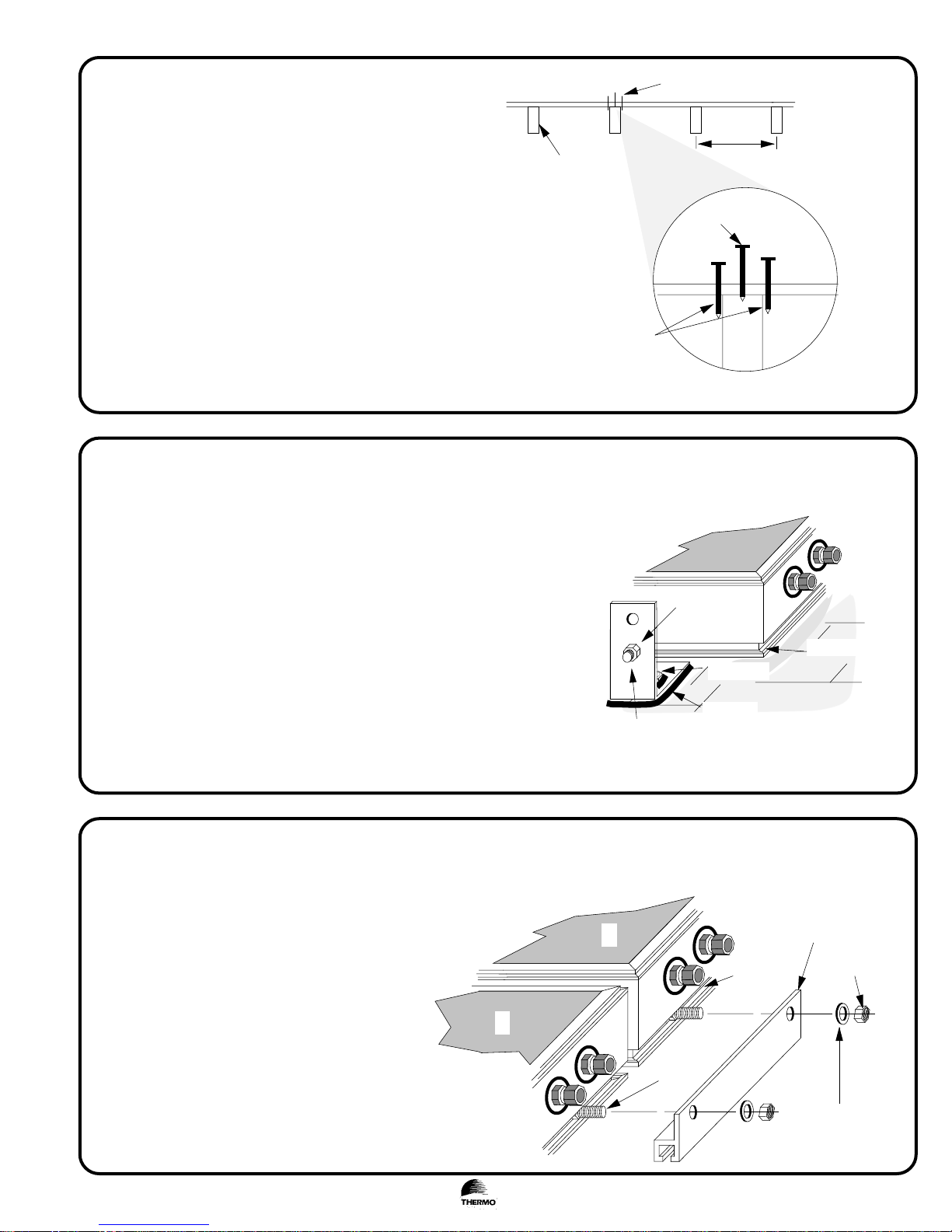
Locating Roof Rafters
✍
❏
Locate the rafters directly under the solar collectors,
and at least 8" from the ends of the solar collectors.
In the case of 4' x 8' solar collectors and 24" rafter
spacing, the clips should be mounted six feet apart
(that is, one foot from the edge of the collector).
❏ To find the center of the rafters, lift the shingle and
use small nails to find the two edges of the rafter.
❏ Drill a 1/4" pilot hole in the rafter for each of the
front mounting clips.
1
Flush Mounting Micro-Flo® Solar Collectors
✍
❏ Fill the holes with silicon sealant and secure the two
front clips to the roof using lag bolts. Seal the
perimeter of each mounting clip base with silicon.
roof
rafter
not acceptable
small nails
usually 16" or 24"
acceptable
roof
rafter
❏ Take the A solar collector and slide two 3/8" bolts in
the bolt track.
❏ Loosely fasten these bolts to the bottom hole of the
front mounting clips using a lock washer and nut.
❏ Center the solar collector so that the spacing from
the end of the solar collector to the mounting clip is
equal on both ends. The solar collector ports must
2
3
be on the right hand corner of the solar collector
when, viewed from below.
Optional Second Solar Collector
✍
❏ If you have a two solar collector system, place the
B solar collector above the A solar collector. Make
sure that the ports are on the right hand side.
❏ Using the aluminum channel, fasten collector B to
A as shown in the figure.
❏ Fasten the upper mounting clips (not shown) to
the top of the collector(s), and use lag bolts to
secure them to the rafters in the same manner as
for solar collector A.
❏ Tighten all nuts that secure the collector(s) to the
mounting clips.
A
IN
B
OUT
IN
3/8" bolt
OUT
bolt trac k
al uminum
channel, (6")
3/8" nut
lock
washer
Solar Boiler™ Installation Manual (OG-300), page 3 of 14IN.410.06.DEC/99
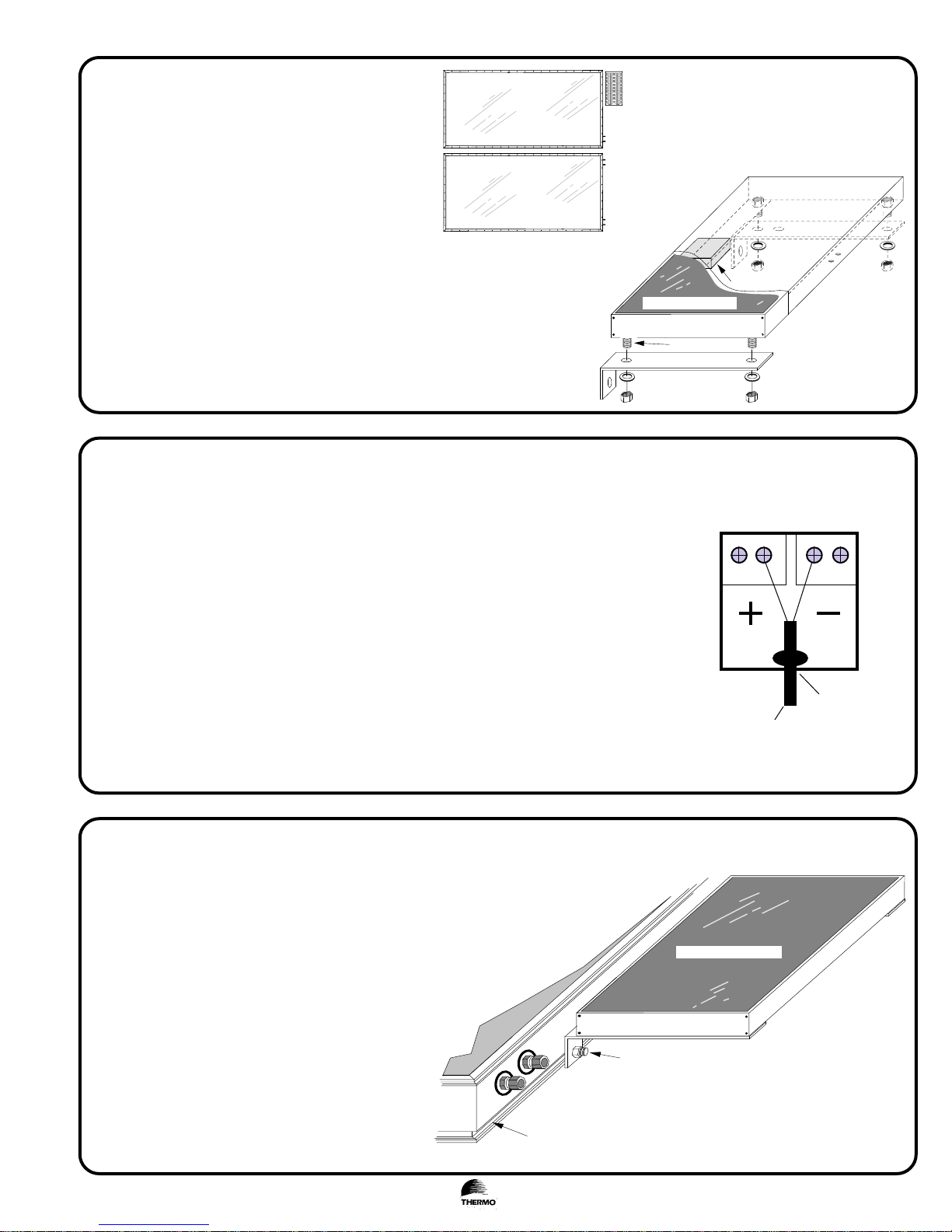
Preparing the photovoltaic module
3/ 8" nut and
lock was her
3/8"
bolt
Photovolta ic module
junction box
A
B
PV
✍
❏ Attach the two large aluminum brackets to the
photovoltaic module using the 3/8" bolts, nuts, and
lock washers supplied.
❏ Make sure both aluminum angle brackets are securely
fastened to the photovoltaic module.
❏ The location of the PV module should be as shown
in the diagram. It is recommended that it be located
towards the top of the collectors so that snow will
easily fall off.
4
Wiring the photovoltaic module
✍
❏
The photovoltaic module comes with an electrical junction box located on the back of the
module. Open the box, and note the positive terminal marked "+" and the negative
terminal marked "-". (Follow the diagram on the back of the PV module)
Junction box
❏ 16/2 wire is supplied with your Solar Boiler™. Drill a small 1/4" hole in the junction
box and slip the wire through. Tie a knot in the wire so that it can not be pulled out of
the box. Connect the black wire to the "+" terminal, and the white wire to the "-"
terminal.
❏ Seal the hole in the junction box wire hole with silicon. Close the junction box securely.
CAUTION: The photovoltaic module produces electricity when exposed to sunlight. To
5
avoid any chance of shock, cover the photovoltaic module with a towel during installation. The photovoltaic module is rated for 1.2 amps, 17.0 volts, and 20 watts.
Locating the photovoltaic module
✍
❏
Locate the photovoltaic module as shown in the
diagram. Using the 3/8" bolts, washer, and nuts,
attach the photovoltaic module to the "B"
collector bolt track as shown in the diagram.
Tighten the nuts securely. The location should be
as close to the top of the "B" collector as possible.
It can be on either the left hand side or the right
hand side.
black wire
16/2 wire
Photovolta ic module
white wire
knot
seal with silicon
6
"B"
Collector
bolt
3/ 8" bolt, washer,
nut
Solar Boiler™ Installation Manual (OG-300), page 4 of 14IN.410.06.DEC/99
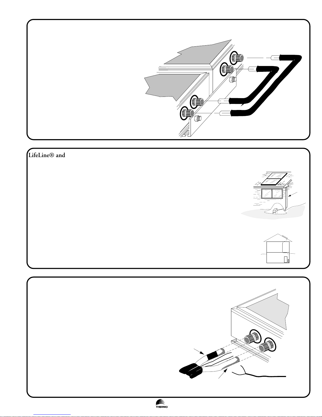
LifeLine® connection between collector A and B
✍
❏
Remove the orange caps from the fittings on the
collectors. Turn the 3/8" compression nuts on
the fitting body until finger tight.
❏ Insert the two 3/8" copper tubes into the ports as
shown.
❏ Using a 11/16" and a 5/8" wrench, tighten the
nuts one full turn.
IMPORTANT: The 11/16" wrench is required to
prevent the fitting body from rotating while
turning the nut with the 5/8" wrench.
7
LifeLine® and CopperTube Kit Installation (For ease, the term "LifeLIne®" will be used
in the manual to refer to both.)
✍
• LifeLine® is used to connect the Solar Boiler™ module to the solar collectors.
• Locate the solar collectors as close as possible to the Solar Boiler™ module without compromising
collector orientation. This will minimize the length of LifeLine® required to connect the Solar Boiler™
to the solar collectors.
OUT
IN
OUT
IN
B
A
LifeLine® tubing
• Run the LifeLine® to the solar collectors via an unused space or closet. Note: All LifeLine® installed
in the horizontal position must slope down 1/4" for every horizontal foot.
• Secure the LifeLine® at intervals of 6 feet with the clamps. Do not kink the tube.
• Do not cut the LifeLine® until you are absolutely sure there is adequate length available.
8
• Insulate the entire length of LifeLine® with insulation provided.
LifeLine® roof penetration
✍
❏
Make a roof penetration at a position 6" - 8" horizontally
away from the bottom “A” collector ports.
❏ Pass the LifeLine® through the roof penetration from below.
Clamp the LifeLine® to the truss. Do not crimp the
LifeLine®. Mark one of the copper tubes with tape on both
ends to identify it as the supply line. It will be connected to
the "IN" port of the "A" collector and to the pump or
"OUT" port of the Solar Boiler module.
❏ Use a 3/8" tube bender to bend the copper tubes so that they
may be inserted to the bottom ports of the "A" collector.
9
3/8" copper t ube
(marke d wit h
tape )
3/8" copper
tube
IN
White wire (–)
Black w ire (+)
OUT
Wire from Photovoltaic
module
Solar Boiler™ Installation Manual (OG-300), page 5 of 14IN.410.06.DEC/99
 Loading...