

Thermo Dynamics CWL GS, CWL GS DV, NCWL GS, NCWL GS DV Installation, Operation & Maintenance Manual
CWL-GS Series
Models CWL GS, CWL GS DV, NCWL GS, NCWL GS DV
Gas Fired Packaged Boiler
Installation
Operation
Maintenance
Manual
Thermo-Dynamics Boiler Company
ROUTE 61 • P.O. BOX 325 • SCHUYLKILL HAVEN, PA 17972
TEL (570) 385-0731 • FAX (570) 385-5304
WEB www.thermodynamicsboiler.com • EMAIL sales@thermodynamicsboiler.com
www.thermodynamicsboiler.com

FOR YOUR SAFETY READ BEFORE OPERATING
WARNING: If you do not follow these instructions exactly, a fire or explosion
may result causing property damage, personal injury or loss of life
A. This appliance does not have a pilot. It is
equipped with an ignition device which automatically lights the burner. Do not try to light
the burner by hand.
B. BEFORE OPERATING smell all around the
appliance area for gas. Be sure to smell next
to the floor because some gas is heavier than
air and will settle to the floor.
WHAT TO DO IF YOU SMELL GAS
*Do not try to light any appliance.
*Do not touch any electric switch; do not
use any phone in the building.
*Immediately call your gas supplier from a
neighbors phone. Follow the gas supplier’s
instructions.
OPERATING INSTRUCTIONS
*If you cannot reach your gas supplier, call the
fire department.
C. Use only your hand to push in or turn the
gas control knob. Never use tools. If the knob
will not push in or turn by hand, don’t try to
repair it, call a qualified service technician.
Force or attempted repair may result in a fire
or explosion.
D. Do not use this appliance if any part has
been under water. Immediately call a qualified
service technician to inspect the appliance
and to replace any part of the control system
and any gas control which has been under
water.
1
. STOP! Read the safety information above
on this label.
2. Set the thermostat to lowest setting.
3. Turn off all electric power to the appliance.
4. This device is equipped with an ignition
device which automatically lights the burner.
Do not try to light the burner by hand.
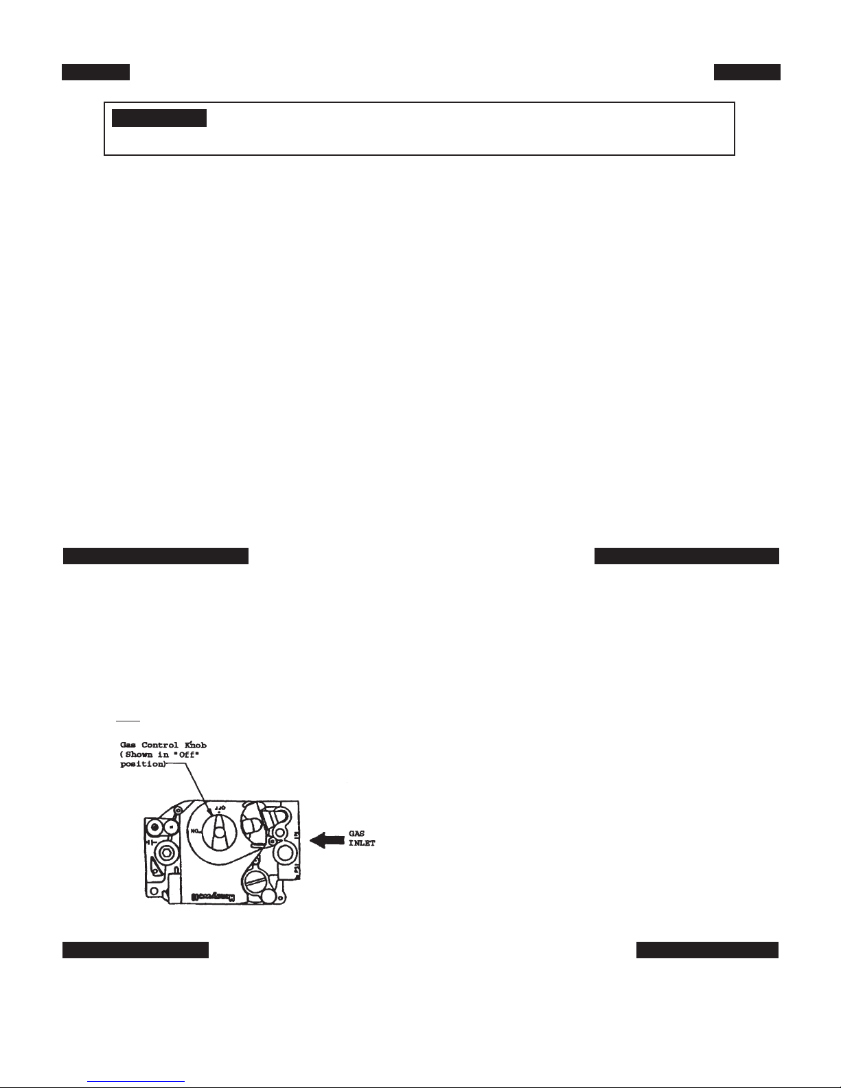
5. If the gas control knob is not in the “OFF”
position, turn the knob clockwise to ‘OFF”.
6. Wait five (5) minutes to clear out any gas.
Then smell for gas, including near the floor.
If you smell gas, STOP! Follow “B” in the
safety information above on this label. If
you do not smell gas, go to the next step.
7. Turn gas control knob counterclockwise
to “ON”.
8. Turn on all electric power to the appliance.
9. Set thermostat to the desired setting.
10. If the appliance will not operate, follow the
instructions “To Turn Off Gas To
Appliance” and call your service
technician or gas supplier.
TO TURN OFF GAS TO APPLIANCE
1. Set the thermostat to lowest setting
2. Turn off all electric power to the appliance if service is to be performed.
3. To turn off gas to appliance, turn the gas control knob clockwise to “OFF”.
i

Contents
Safety Instructions i
Service Policy 1
Component Arrangement 3
Installation 3
Operation 12
Maintenance 14
Trouble Shooting 16
Parts List 21
Product Features
• ASME Coded Boiler Registered with National Board
• Fully Insulated Heat Exchanger with Powder-Coated Cabinet
• Packaged with Standard Five Gallon per Minute Tankless Coil
For Domestic Hot Water (CWL Models Only)
• NCWL Model Available Without Tankless Coil
• Equipped with Triple Aquastat, Circulator, and Temperature/Altitude Gauge
(CWL Models Only)
• Equipped with Cold Start Aquastat, Circulator, and Temperature/Altitude
Gauge (NCWL Models Only)
• Additional Orifices Provided
• Lifetime Limited Warranty
• Available as Direct Vent
ii

Service Policy
Congratulations on the purchase of your boiler. At Thermo-Dynamics Boiler
Company we pride ourselves on the design and construction of our product. Our
intent is to furnish you with a high quality appliance that will provide you and your
family with years of trouble free service.
In order to maintain peak performance of your boiler, it is recommended that
the burner/boiler be serviced annually, preferably prior to the onset of the winter
heating season. Servicing of your appliance must be performed by a qualified heating technician. You should utilize a qualified heating technician familiar with your
installation to manage your heater and perform periodic maintenance. Proper care
and maintenance of your boiler will allow you to enjoy the benefits of your new purchase as well as extend its long useful life.
In the event that your serviceman encounters difficulty with the boiler, he/she
shall contact the distributor from which the product was purchased. The distributor,
in turn, will contact the Thermo-Dynamics sales representative for your area. By
adhering to this protocol, Thermo-Dynamics will provide you with responsive and
unparalleled service. We realize the importance of what our product means to you
and your family and our goal is to get your unit up and running as quickly as possible.
Thank you for purchasing the Thermo-Dynamics boiler. Again, it is our intent
to provide you with a high quality trouble free product that will be part of your family for many years to come. Please consider Thermo-Dynamics Boiler Company in
the future for all of your home heating needs.
1

IMPORTANT
l
Read carefully and consult drawings before beginning work.
l
The CWL-GS is factory assembled and packaged. Check shipping list as the unit and accompanying cartons are unpacked. Report shortages or damage to the delivering carrier immediately.
l
Safe lighting and other performance criteria were met with the gas manifold and control
assembly provided on the boiler when the boiler underwent tests as specified in Gas Fired
Low-Pressure Steam and Hot Water Boilers ANSI Z21.13.
l
The instructions, drawings, and data included in this manual are only guidelines. The equipment shall be installed in accordance with the installation requirements of the authority having jurisdiction or in the absence of such requirements to the current edition of the National
Fuel Gas Code ANSI Z223.1. (Available from the American Gas Association, Pleasant Valley
Road, Cleveland, Ohio 44134)
l
When required by the authority having jurisdiction, the installation must conform to the
American Society of Mechanical Engineers Safety Code for Control and Safety Devices for
Automatically Fired Boilers, No. CSD-1.
l
This Instruction Manual shall be kept near the boiler for future reference.
! WARNING:
THIS PRODUCT MUST BE INSTALLED BY A LICENSED PLUMBER OR GAS FITTER WHEN
INSTALLED WITHIN THE COMMONWEALTH OF MASSACHUSETTS.
IMPROPER INSTALLATION, ADJUSTMENT, ALTERATION, SERVICE OR MAINTENANCE OF
THIS BOILER MAY CAUSE INJURY OR PROPERTY DAMAGE.
IF YOU SMELL GAS OR SUSPECT A GAS LEAK, TURN OFF GAS AT THE MANUAL SERVICE VALVE AND EVACUATE THE HOUSE. DO NOT TRY TO LIGHT ANY APPLIANCE. DO
NOT TOUCH ANY ELECTRICAL SWITCHES OR TELEPHONES IN THE BUILDING UNTIL
YOU ARE SURE NO GAS REMAINS IN THE AIR.
COMPLIANCE WITH ALL APPLICABLE CODES IS THE SOLE RESPONSIBILITY OF THE
INSTALLER.
2

Figure 1
Component Arrangement
Installation
I. GENERAL
CWL-GS Series hot water boilers are high quality, high efficiency gas fired vertical fire tube heating units.
The in stal la tion of the unit shall be in accordance with regulations of the authorities having jurisdiction.
Refer to Local installation Codes for Gas Burning Equipment, for recommended installation practice.
The CWL must be installed with the factory assembled jacket intact.
II. FREIGHT CLAIMS
All units should be inspected for damage upon arrival. Concealed damage claims should be filed
immediately against the carrier by the consignee. The carrier is responsible for taking prompt action on all
claims.
III. SIZING
A complete heat loss calculation of the structure is necessary to choose the proper size unit.
Oversizing will result in short cycling and inefficient operation. In order to insure proper sizing of the unit,
domestic hot water re quire ments and the structure heat load must be calculated.
Replacement boilers should not be sized from the firing rate of the old boiler. A DOE sponsored
study indicates 65% of the heating units in U.S. homes are substantially oversized.
3

TABLE 1 – SPECIFICATIONS
Model: 120 140 160
Boiler Specifications
Firing Rate CFM 1.95 2.28 2.60
Input BTU/HR 120,000 140,000 160,000
DOE Capacity BTU/HR 100,000 115,000 130,000
Net Rate BTU/HR 87,000 100,000 113,000
Val. Cap. Lbs/HR 160 160 160
Max. W.P. PSI 30 30 30
AFUE 82.6 81.1 80.5
Boiler Dimensions
Water Content 15 Gal. 15 Gal. 15 Gal.
Coil Capacity* 5 Gal. 5 Gal. 5 Gal.
A) Jacket Height 29-1/2 29-1/2 29-1/2
B) Jacket Width 21 21 21
C) Coil Supply Height 22 22 22
D) Supply Height (Hydronic) 27-1/2 27-1/2 27-1/2
E) Burner Height 7-7/8 7-7/8 7-7/8
F) Hydronic Return Height 15-1/2 15-1/2 15-1/2
G) Flue Pipe Dia. 555
H) Washout (Alt. Return Height) 3-1/2 3-1/2 3-1/2
I) Jacket Depth (Inc. Flange) 22 22 22
Depth Front to Rear w/Burner 34-1/2" 34-1/2" 34-1/2"
Hydronic Supply Size 1-1/4 1-1/4 1-1/4
Hydronic Return Size 1-1/4 1-1/4 1-1/4
Washout Size (Alt. Return) 1-1/4 (2) 1-1/4 (2) 1-1/4 (2)
* Intermittent draw: 5 minute draw and 5 minute waiting period
4

IV. LOCATION
Place the boiler on a level floor, preferably raised and as near to the chimney or venting device as
possible. Allow clearances as follows in accordance with local codes and NFPA-54. (For clearances less
than the listed values, consult NFPA-54 Table 6.2.3(B).
MINIMUM CLEARANCE TO COMBUSTIBLE MATERIALS
Sides - 0”
Rear - 0”
Front - 12”
Chimney Connector - 18”
Top - 18” for cleaning
The CWL-GS zero clearance rating is attributed
to its “Wet-Leg” Design. The boiler features a wall of
water on all four sides as well as the area directly above
the combustion chamber, thereby eliminating hazardous
chamber burn-through conditions and can be placed on
combustible flooring in accordance with U.L. 726.
V. AIR FOR COMBUSTION AND VENTILATION
The unit must be installed where provisions exist for combustion and ventilation air. Ordinarily, provi-
sions may be furnished by the following methods.
A. Utility Room or Closet
In buildings of tight construction, including most modern homes, you should provide an opening,
con nect ing to a well ventilated attic, crawl space or directly with the outdoors. The opening should have a
minimum free area of 1 square inch per 1,000 Btu per hour of total input for all appliances in the enclosure
and should terminate below the burner level. Boilers installed in a confined area or closet must have two
ventilation openings in the closet door. Each opening should have a free area of not less than 1 square inch
per 1,000 Btu of the total input for all appliances in the enclosure. One opening located near the top of the
enclosure and one near the bottom.
B. Basement
1. Where a boiler is installed in a full basement, infiltration is normally adequate to provide air for
combustion.
2. Buildings of tight construction where the basement windows are weather stripped, one opening
com mu ni cat ing with a well ventilated attic or with the outdoors should be provided. The opening should
have a minimum free area of 1 square inch per 1,000 Btu per hour of total input for all appliances in the
inclosure.
C. Special Conditions
Where a boiler is located in an area where the operation of exhaust fans, kitchen ventilation sys-
tems, clothes dryers, or fire places may create conditions of unsatisfactory combustion or venting, special provisions should be made for additional air for combustion, as specified by local authority.
VI. BOILER PIPING
The CWL-GS Series of boilers is equipped with a built in Air Scoop. This feature allows quiet air free
operation of your hot water system by assuring the removal of air pockets without the use of Air Scoops
(see Figure 2) to trap noisy air.
5
 Loading...