

Thermo Dynamics CWL GS, CWL GS DV, NCWL GS, NCWL GS DV Installation, Operation & Maintenance Manual
Page 1
CWL-GS Series
Models CWL GS, CWL GS DV, NCWL GS, NCWL GS DV
Gas Fired Packaged Boiler
Installation
Operation
Maintenance
Manual
Thermo-Dynamics Boiler Company
ROUTE 61 • P.O. BOX 325 • SCHUYLKILL HAVEN, PA 17972
TEL (570) 385-0731 • FAX (570) 385-5304
WEB www.thermodynamicsboiler.com • EMAIL [email protected]
www.thermodynamicsboiler.com
Page 2

Page 3
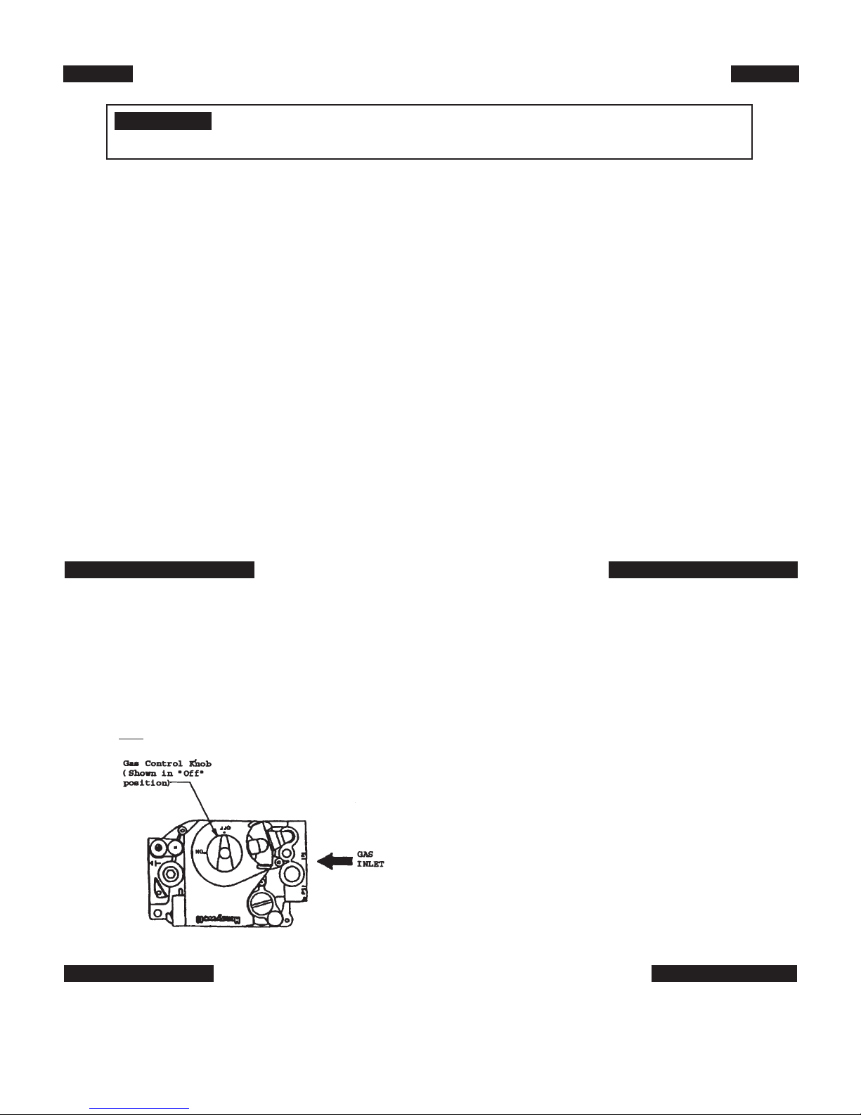
FOR YOUR SAFETY READ BEFORE OPERATING
WARNING: If you do not follow these instructions exactly, a fire or explosion
may result causing property damage, personal injury or loss of life
A. This appliance does not have a pilot. It is
equipped with an ignition device which automatically lights the burner. Do not try to light
the burner by hand.
B. BEFORE OPERATING smell all around the
appliance area for gas. Be sure to smell next
to the floor because some gas is heavier than
air and will settle to the floor.
WHAT TO DO IF YOU SMELL GAS
*Do not try to light any appliance.
*Do not touch any electric switch; do not
use any phone in the building.
*Immediately call your gas supplier from a
neighbors phone. Follow the gas supplier’s
instructions.
OPERATING INSTRUCTIONS
*If you cannot reach your gas supplier, call the
fire department.
C. Use only your hand to push in or turn the
gas control knob. Never use tools. If the knob
will not push in or turn by hand, don’t try to
repair it, call a qualified service technician.
Force or attempted repair may result in a fire
or explosion.
D. Do not use this appliance if any part has
been under water. Immediately call a qualified
service technician to inspect the appliance
and to replace any part of the control system
and any gas control which has been under
water.
1
. STOP! Read the safety information above
on this label.
2. Set the thermostat to lowest setting.
3. Turn off all electric power to the appliance.
4. This device is equipped with an ignition
device which automatically lights the burner.
Do not try to light the burner by hand.
5. If the gas control knob is not in the “OFF”
position, turn the knob clockwise to ‘OFF”.
6. Wait five (5) minutes to clear out any gas.
Then smell for gas, including near the floor.
If you smell gas, STOP! Follow “B” in the
safety information above on this label. If
you do not smell gas, go to the next step.
7. Turn gas control knob counterclockwise
to “ON”.
8. Turn on all electric power to the appliance.
9. Set thermostat to the desired setting.
10. If the appliance will not operate, follow the
instructions “To Turn Off Gas To
Appliance” and call your service
technician or gas supplier.
TO TURN OFF GAS TO APPLIANCE
1. Set the thermostat to lowest setting
2. Turn off all electric power to the appliance if service is to be performed.
3. To turn off gas to appliance, turn the gas control knob clockwise to “OFF”.
i
Page 4

Contents
Safety Instructions i
Service Policy 1
Component Arrangement 3
Installation 3
Operation 12
Maintenance 14
Trouble Shooting 16
Parts List 21
Product Features
• ASME Coded Boiler Registered with National Board
• Fully Insulated Heat Exchanger with Powder-Coated Cabinet
• Packaged with Standard Five Gallon per Minute Tankless Coil
For Domestic Hot Water (CWL Models Only)
• NCWL Model Available Without Tankless Coil
• Equipped with Triple Aquastat, Circulator, and Temperature/Altitude Gauge
(CWL Models Only)
• Equipped with Cold Start Aquastat, Circulator, and Temperature/Altitude
Gauge (NCWL Models Only)
• Additional Orifices Provided
• Lifetime Limited Warranty
• Available as Direct Vent
ii
Page 5

Service Policy
Congratulations on the purchase of your boiler. At Thermo-Dynamics Boiler
Company we pride ourselves on the design and construction of our product. Our
intent is to furnish you with a high quality appliance that will provide you and your
family with years of trouble free service.
In order to maintain peak performance of your boiler, it is recommended that
the burner/boiler be serviced annually, preferably prior to the onset of the winter
heating season. Servicing of your appliance must be performed by a qualified heating technician. You should utilize a qualified heating technician familiar with your
installation to manage your heater and perform periodic maintenance. Proper care
and maintenance of your boiler will allow you to enjoy the benefits of your new purchase as well as extend its long useful life.
In the event that your serviceman encounters difficulty with the boiler, he/she
shall contact the distributor from which the product was purchased. The distributor,
in turn, will contact the Thermo-Dynamics sales representative for your area. By
adhering to this protocol, Thermo-Dynamics will provide you with responsive and
unparalleled service. We realize the importance of what our product means to you
and your family and our goal is to get your unit up and running as quickly as possible.
Thank you for purchasing the Thermo-Dynamics boiler. Again, it is our intent
to provide you with a high quality trouble free product that will be part of your family for many years to come. Please consider Thermo-Dynamics Boiler Company in
the future for all of your home heating needs.
1
Page 6

IMPORTANT
l
Read carefully and consult drawings before beginning work.
l
The CWL-GS is factory assembled and packaged. Check shipping list as the unit and accompanying cartons are unpacked. Report shortages or damage to the delivering carrier immediately.
l
Safe lighting and other performance criteria were met with the gas manifold and control
assembly provided on the boiler when the boiler underwent tests as specified in Gas Fired
Low-Pressure Steam and Hot Water Boilers ANSI Z21.13.
l
The instructions, drawings, and data included in this manual are only guidelines. The equipment shall be installed in accordance with the installation requirements of the authority having jurisdiction or in the absence of such requirements to the current edition of the National
Fuel Gas Code ANSI Z223.1. (Available from the American Gas Association, Pleasant Valley
Road, Cleveland, Ohio 44134)
l
When required by the authority having jurisdiction, the installation must conform to the
American Society of Mechanical Engineers Safety Code for Control and Safety Devices for
Automatically Fired Boilers, No. CSD-1.
l
This Instruction Manual shall be kept near the boiler for future reference.
! WARNING:
THIS PRODUCT MUST BE INSTALLED BY A LICENSED PLUMBER OR GAS FITTER WHEN
INSTALLED WITHIN THE COMMONWEALTH OF MASSACHUSETTS.
IMPROPER INSTALLATION, ADJUSTMENT, ALTERATION, SERVICE OR MAINTENANCE OF
THIS BOILER MAY CAUSE INJURY OR PROPERTY DAMAGE.
IF YOU SMELL GAS OR SUSPECT A GAS LEAK, TURN OFF GAS AT THE MANUAL SERVICE VALVE AND EVACUATE THE HOUSE. DO NOT TRY TO LIGHT ANY APPLIANCE. DO
NOT TOUCH ANY ELECTRICAL SWITCHES OR TELEPHONES IN THE BUILDING UNTIL
YOU ARE SURE NO GAS REMAINS IN THE AIR.
COMPLIANCE WITH ALL APPLICABLE CODES IS THE SOLE RESPONSIBILITY OF THE
INSTALLER.
2
Page 7

Figure 1
Component Arrangement
Installation
I. GENERAL
CWL-GS Series hot water boilers are high quality, high efficiency gas fired vertical fire tube heating units.
The in stal la tion of the unit shall be in accordance with regulations of the authorities having jurisdiction.
Refer to Local installation Codes for Gas Burning Equipment, for recommended installation practice.
The CWL must be installed with the factory assembled jacket intact.
II. FREIGHT CLAIMS
All units should be inspected for damage upon arrival. Concealed damage claims should be filed
immediately against the carrier by the consignee. The carrier is responsible for taking prompt action on all
claims.
III. SIZING
A complete heat loss calculation of the structure is necessary to choose the proper size unit.
Oversizing will result in short cycling and inefficient operation. In order to insure proper sizing of the unit,
domestic hot water re quire ments and the structure heat load must be calculated.
Replacement boilers should not be sized from the firing rate of the old boiler. A DOE sponsored
study indicates 65% of the heating units in U.S. homes are substantially oversized.
3
Page 8

TABLE 1 – SPECIFICATIONS
Model: 120 140 160
Boiler Specifications
Firing Rate CFM 1.95 2.28 2.60
Input BTU/HR 120,000 140,000 160,000
DOE Capacity BTU/HR 100,000 115,000 130,000
Net Rate BTU/HR 87,000 100,000 113,000
Val. Cap. Lbs/HR 160 160 160
Max. W.P. PSI 30 30 30
AFUE 82.6 81.1 80.5
Boiler Dimensions
Water Content 15 Gal. 15 Gal. 15 Gal.
Coil Capacity* 5 Gal. 5 Gal. 5 Gal.
A) Jacket Height 29-1/2 29-1/2 29-1/2
B) Jacket Width 21 21 21
C) Coil Supply Height 22 22 22
D) Supply Height (Hydronic) 27-1/2 27-1/2 27-1/2
E) Burner Height 7-7/8 7-7/8 7-7/8
F) Hydronic Return Height 15-1/2 15-1/2 15-1/2
G) Flue Pipe Dia. 555
H) Washout (Alt. Return Height) 3-1/2 3-1/2 3-1/2
I) Jacket Depth (Inc. Flange) 22 22 22
Depth Front to Rear w/Burner 34-1/2" 34-1/2" 34-1/2"
Hydronic Supply Size 1-1/4 1-1/4 1-1/4
Hydronic Return Size 1-1/4 1-1/4 1-1/4
Washout Size (Alt. Return) 1-1/4 (2) 1-1/4 (2) 1-1/4 (2)
* Intermittent draw: 5 minute draw and 5 minute waiting period
4
Page 9

IV. LOCATION
Place the boiler on a level floor, preferably raised and as near to the chimney or venting device as
possible. Allow clearances as follows in accordance with local codes and NFPA-54. (For clearances less
than the listed values, consult NFPA-54 Table 6.2.3(B).
MINIMUM CLEARANCE TO COMBUSTIBLE MATERIALS
Sides - 0”
Rear - 0”
Front - 12”
Chimney Connector - 18”
Top - 18” for cleaning
The CWL-GS zero clearance rating is attributed
to its “Wet-Leg” Design. The boiler features a wall of
water on all four sides as well as the area directly above
the combustion chamber, thereby eliminating hazardous
chamber burn-through conditions and can be placed on
combustible flooring in accordance with U.L. 726.
V. AIR FOR COMBUSTION AND VENTILATION
The unit must be installed where provisions exist for combustion and ventilation air. Ordinarily, provi-
sions may be furnished by the following methods.
A. Utility Room or Closet
In buildings of tight construction, including most modern homes, you should provide an opening,
con nect ing to a well ventilated attic, crawl space or directly with the outdoors. The opening should have a
minimum free area of 1 square inch per 1,000 Btu per hour of total input for all appliances in the enclosure
and should terminate below the burner level. Boilers installed in a confined area or closet must have two
ventilation openings in the closet door. Each opening should have a free area of not less than 1 square inch
per 1,000 Btu of the total input for all appliances in the enclosure. One opening located near the top of the
enclosure and one near the bottom.
B. Basement
1. Where a boiler is installed in a full basement, infiltration is normally adequate to provide air for
combustion.
2. Buildings of tight construction where the basement windows are weather stripped, one opening
com mu ni cat ing with a well ventilated attic or with the outdoors should be provided. The opening should
have a minimum free area of 1 square inch per 1,000 Btu per hour of total input for all appliances in the
inclosure.
C. Special Conditions
Where a boiler is located in an area where the operation of exhaust fans, kitchen ventilation sys-
tems, clothes dryers, or fire places may create conditions of unsatisfactory combustion or venting, special provisions should be made for additional air for combustion, as specified by local authority.
VI. BOILER PIPING
The CWL-GS Series of boilers is equipped with a built in Air Scoop. This feature allows quiet air free
operation of your hot water system by assuring the removal of air pockets without the use of Air Scoops
(see Figure 2) to trap noisy air.
5
Page 10

he 1-1/4” supply line or riser tapping in the top of the boiler extends approximately 1” below the top
T
or waterline of the boiler, thus allowing only air-free water to enter the supply to the heating system. The
air trapped in the top of the boiler must be purged through the 3/4" vent tapping by using an Automatic
Float Vent, a Manual Vent or piped into a conventional expansion tank. (See Figure 2 and 4)
The recommended locations of circulators, expansion tanks, etc. are illustrated in Figure 4. Relief valve
discharge and drain valve piping should be piped to a safe place of discharge. All plugs and water connections should be checked for leaks upon installation and annually.
VII. TANKLESS WATER HEATER PIPING
The tankless heater may be connected as shown in Figure 4.
A mixing valve (not supplied) may be used to reduce the water temperature at kitchen or bathroom
taps. High temperature water for a dishwasher may be obtained by piping as shown.
The nuts that secure the tankless coil flange should be tightened before the boiler is filled with water, after
initial firing and every year during annual maintenance. DETERIORATION DUE TO COIL GASKET LEAKS
SHALL VOID WAR RAN TY.
VIII. BURNER AND CONTROLS
The gas burner is factory mounted and wired on all units. The ignition safety shut-off device must be
tested when the unit is in operation. To do this turn gas supply off. Set the thermostat or controller above
room temperature to call for heat. Watch for the igniter to heat up. Determine the length of time the gas valve
stays open. Use a volt meter to verify voltage present at the gas valve. The length of time that power is
applied to the gas valve should not exceed 4.0 seconds. To relight, see lighting and shut-down instructions.
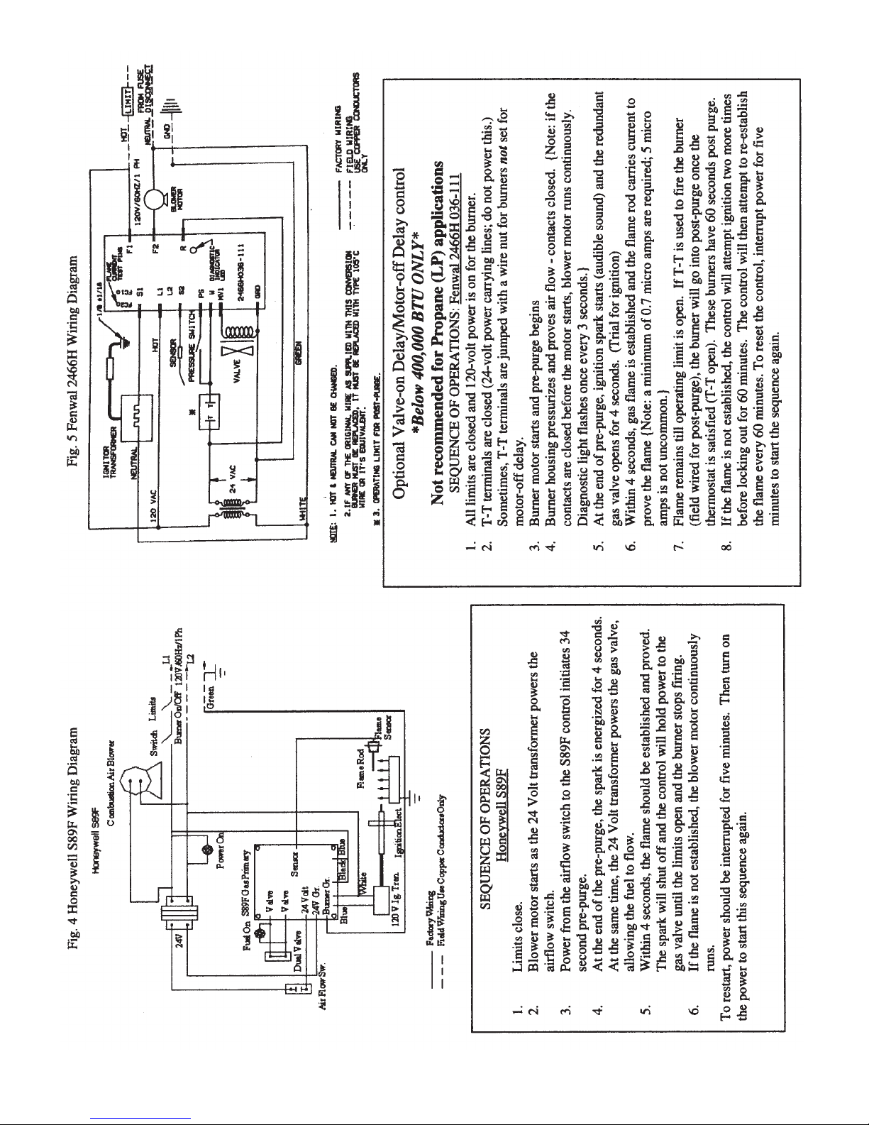
A. Primary Control - Honeywell S89F
The CWL-GS Series Boiler is equipped with a Honeywell S89F Controller. The Controller is a 24 vac
micro processor based control with electronic ignition and a combustion blower relay. The controller uses
full time flame sensing to continually monitor flame quality with a minimum current of 0.7 microamps. In
addition the controller is set for a 34 second pre purge. In the event of a flame failure, the control shall try
for ignition 3 times before going into lockout. Recovery from lockout requires a manual reset by adjusting
the thermostat. Alternatively, the 24 vac power supply may be disconnected for a period of 5 seconds in
order to reset the control.
CONTROL OPERATION
When a call for heat is received from the thermostat supplying 24 volts to TH/W, the control will check
the pressure switch for normally open contacts. The combustion blower is then energized and once the
pressure switch contacts close, an optional prepurge delay begins and the electronic ignitor is activated.
Following the ignitor heat-up period the gas valve is energized for the trial for ignition period.
When flame is detected during the trial for ignition, the ignitor is de-energized immediately and the gas
valve and combustion blower remains energized. The thermostat, pressure switch, and main burner flame
are constantly monitored to assure the system continues to operate properly. When the thermostat is satisfied and the demand for heat ends, the main valve is de-energized immediately, the control senses the loss
of flame signal and initiates an optional post-purge period before de-energizing the combustion blower.
B. Aquastat Relay L7224 (For CWL Models Only)
This control is installed on the middle of the domestic coil. These immersion type controls are used with
forced hydronic heating systems which include domestic water service. This model provides high limits,
low limits for maintaining minimum boiler water temperature and circulator controls. This control can also
be used for multizone control by using a separate circulator and an R845 relay for each zone. (See Figure
6) The primary control is factory wired to the aquastat relay. These controls working as a system will pre-
6
Page 11
vent the circulator operation if the water temperature is below a predetermined low level. Likewise, if the
water level reaches a predetermined high limit of 205°F, the burner will automatically shut off.
C. Aquastat Relay L7248 (For NCWL Models Only)
This control is installed on the top center of the boiler. These immersion type controls are used with
forced hydronic heating systems which include domestic water service. This model provides high limits for
maintaining maximum boiler water temperature and circulator controls. This control can also be used for
multizone control by using a separate circulator and an R845 relay for each zone. (See Figure 6) The
primary control is factory wired to the aquastat relay. These controls working as a system will prevent the
circulator operation if the water temperature is below a predetermined low level. Likewise, if the water level
reaches a predetermined high limit of 205°F, the burner will automatically shut off.
IX. SEQUENCE OF OPERATION
Forced Circulation Hot Water System with Tankless Heater
When room temperature falls below the thermostat setting, the thermostat calls for heat starting the
burner and circulating pump. The burner and pump continue to operate until room heating requirements
are satisfied (ther mo stat setting is reached), or until boiler water temperature reaches high limit control temperature setting. If the boiler high limit is reached the burner will shut off with the circulator continuing to
operate until the room heating re quire ments are satisfied. If the thermostat continues to call for heat after
the boiler temperature falls below the high limit setting the burner will restart.
The boiler water temperature is normally maintained at 180°F around the tankless coil by the operating control so that an abundance of hot water is available. If the boiler water temperature should fall below
the operating control setting (180-F), the burner will be started again by that control (and the circulating
pump will be prevented from operating) until the operating control setting is satisfied.
X. GAS PIPING
Gas supply piping is to be sized and installed properly in order to provide a supply of gas sufficient to
meet the maximum demand, with minimal loss of pressure between the meter and the boiler.
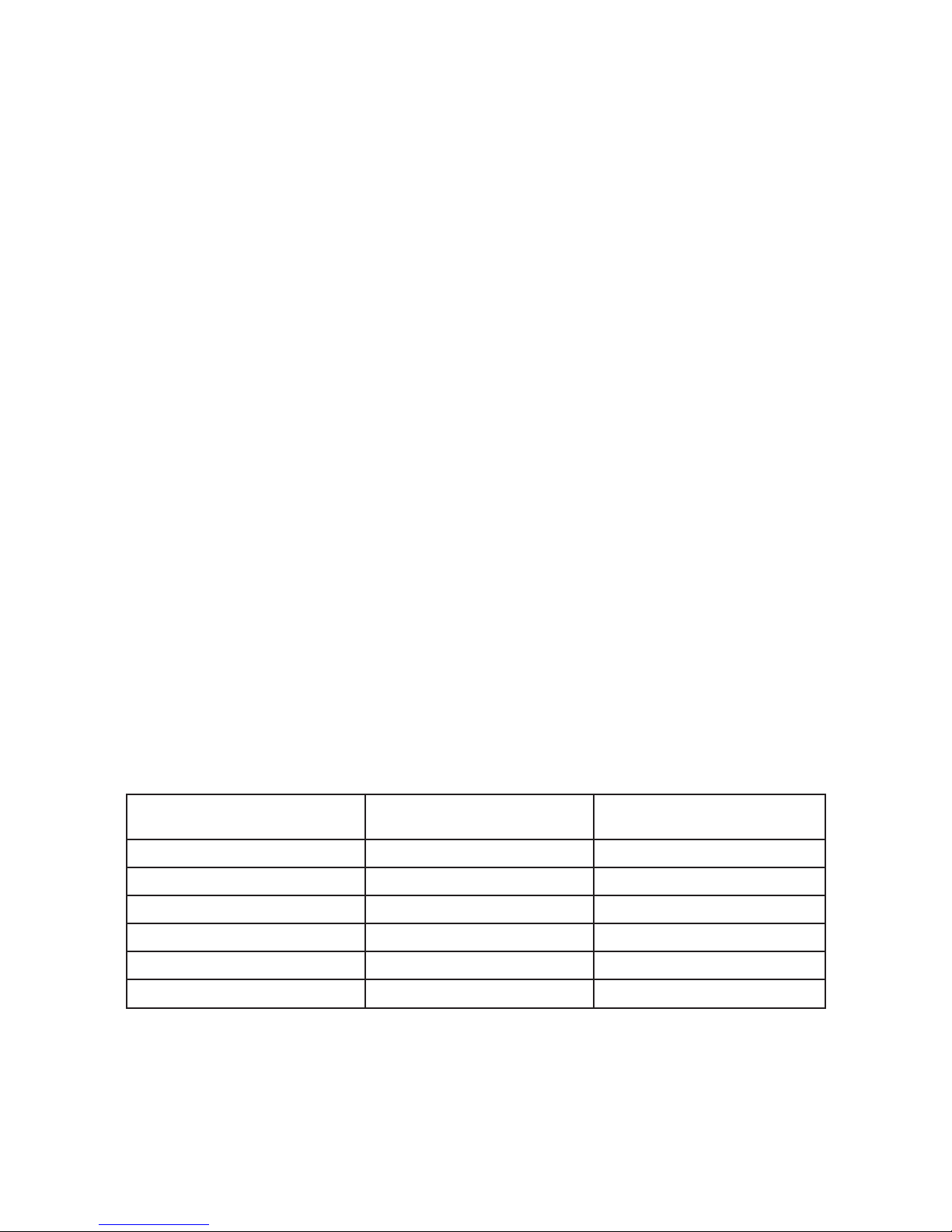
Consult the following table for proper gas pipe sizing. The capacity of pipe in cubic feet per hour for different diameters and lengths, with a pressure drop of 0.3 inches and a specific gravity of 0.60 is shown. No
allowance for an ordinary number of fittings is required.
Table 3 Pipe Capacities
PIPE LENGTH 3/4" PIPE 1" PIPE
(FEET) (Cu. Ft./Hr.) (Cu. Ft./Hr.)
10 278 520
20 190 350
30 152 285
40 130 245
50 115 215
60 105 195
Multipliers to be used with table 1 when the specific gravity of the gas is other than 0.60
Specific Gravity 0.50 0.55 0.60 0.65 0.70
Multiplier 1.10 1.04 1.00 0.962 0.926
Locate a drop pipe adjacent to, but not in front of, the boiler. Locate a tee in the drop pipe at the same
elevation as the gas inlet connection to the boiler. Extend the drop cap as shown in Figure 3 to form a sediment trap.
7
Page 12
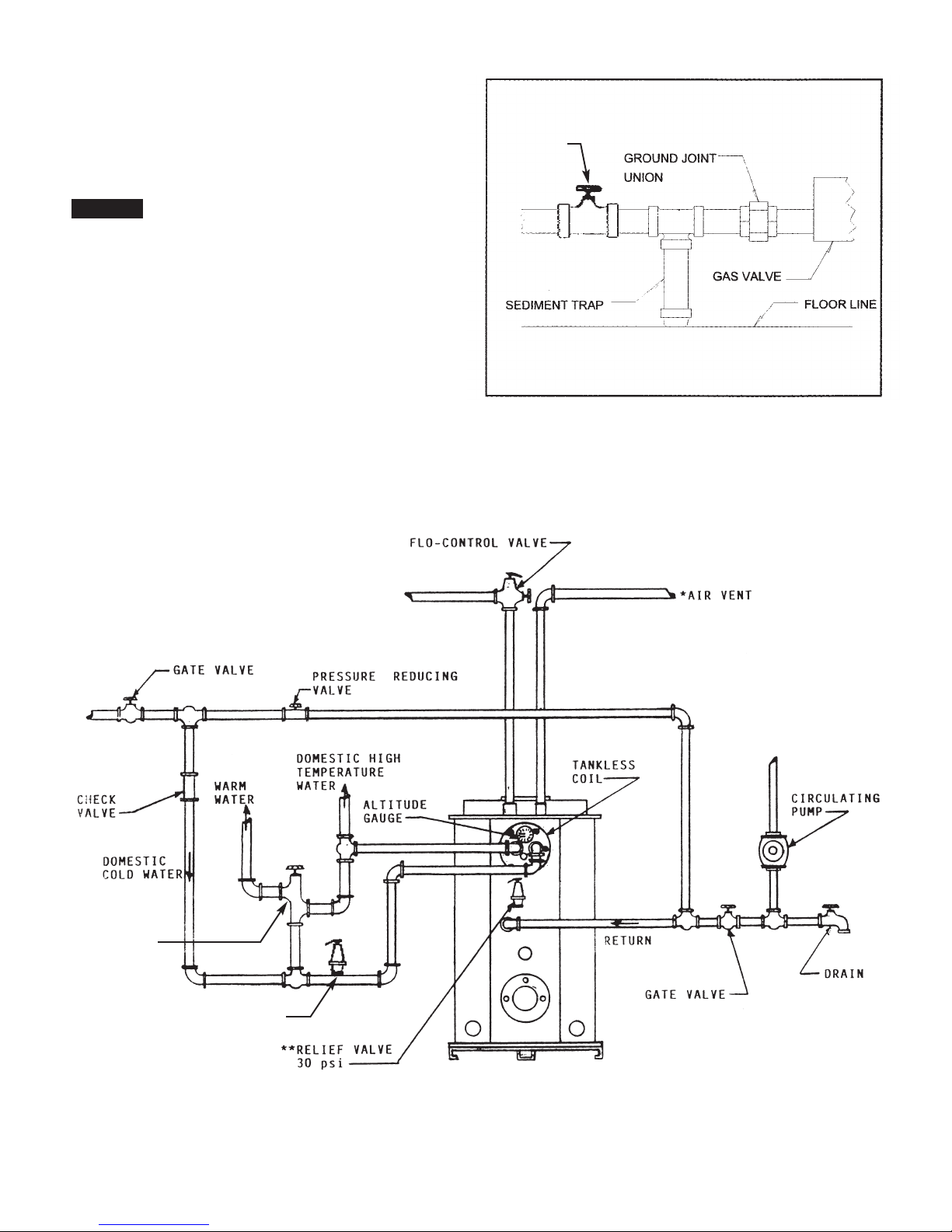
he boiler is equipped with a combination gas
Figure 3 Gas Piping
T
control. Install a ground joint union ahead of the gas
control assembly to permit servicing of the control.
See Figure 3. Install an additional shut-off valve
when a combination gas control is used. See Figure
3 for the suggested location.
! NOTE: WHEN INSTALLING THE BOILER, MAKE
SURE A PIPE COMPOUND RESISTANT TO THE
ACTION OF LIQUEFIED PETROLEUM IS USED.
Check piping for leaks. Always check leaks with
a water and soap solution, or equal. DO NOT USE
A FLAME FOR CHECKING GAS LEAKS.
The boiler and its individual shut-off valve must
be disconnected from the gas supply piping during
any pressure testing of that piping at test pressures
in excess of 0.5 PSIG, or 14 inches water column.
The boiler must be isolated from the gas supply piping by closing its individual manual shut-off valve
during pressure testing of the gas supply piping system at test pressures equal to or less than 0.5 PSIG.
SHUT OFF
BALL VALVE
CWL-GS Boiler Piping
Figure 4
TEMPERING
VALVE
DOMESTIC WATER RELIEF VALVE
* Venting - Refer to Section VI BOILER PIPING
** Relief Valve discharge and drain valve piping should be piped to a safe place of discharge.
8
Page 13
I. FLUE SYSTEM
X
CHIMNEY VENT MODELS
A. Draft
In order to ensure positive pressure over the fire (see specification sheet) and superior boiler performance, the draft in the flue pipe should be set to -0.02. In the event that the pressure is not at the set point,
a draft regulator or draft booster may be used to correct for condition. Any draft control used in the venting system must be of listed type and installed according to local building codes and NFPA-54.
B. Venting System
1. Use only an approved venting system.
2. Flue or vent connector must be the same size or larger than the outlet at the unit, and must be
inserted into but not beyond the inside wall of the chimney flue.
3. The horizontal length of a chimney connector should not exceed 10 ft. unless a draft booster is
used. The connector should be pitched at least 1/4” to the foot toward the unit.
C. Roof Clearances
The chimney flue should extend at least 3 ft. above the highest point at which the chimney comes in
contact with the roof, and no less than 2 ft. above the highest roof surface or structure within 10 ft. horizontally of the chimney.
DIRECT VENT MODELS
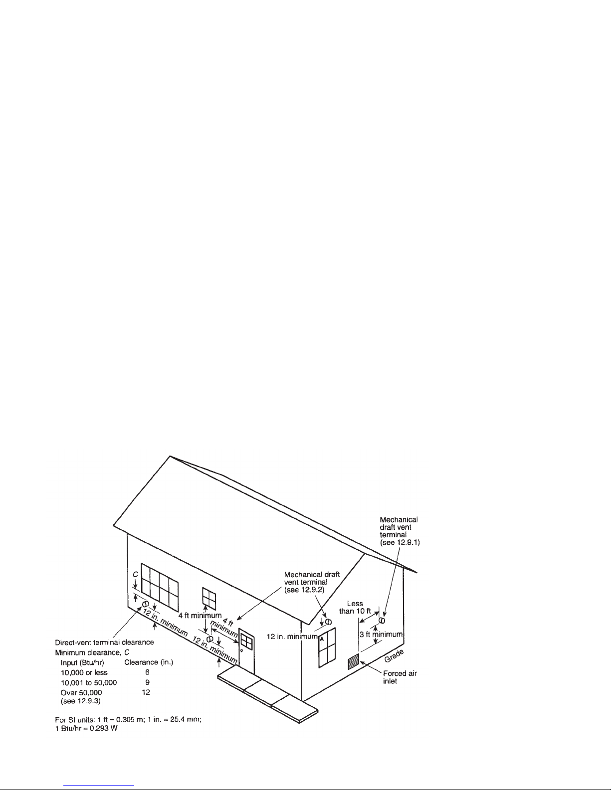
Install the TV-175 Combination Vent Hood by cutting a 7-1/16" by 7-1/16" opening through an exterior wall. Ensure that the location of the hood is 12" above ground and 3' from any opening. The location
must also be in area with sufficient air flow (alcoves and other obstructions such as shrubbery tend to
starve the burner for air). Please see following schematic.
Flash off the opening for the TV-175 Combination Vent Hood. Place additional insulation between the
sides of the hood and the exterior wall to seal the opening.
Connect the air intake and flue from the boiler to the combination vent system (kits are available in 10',
15' and 20' lengths). The 4" duct is for the air intake and the 5" AL 29-4C is for the exhaust. Connect the
joints for the exhaust venting by using a silicon Sealant and tightening the attached cable clamps.
Figure: Terminals of Direct Venting Systems
(taken from NFPA-54 National Fuel Gas Code).
9
Page 14
10
Page 15
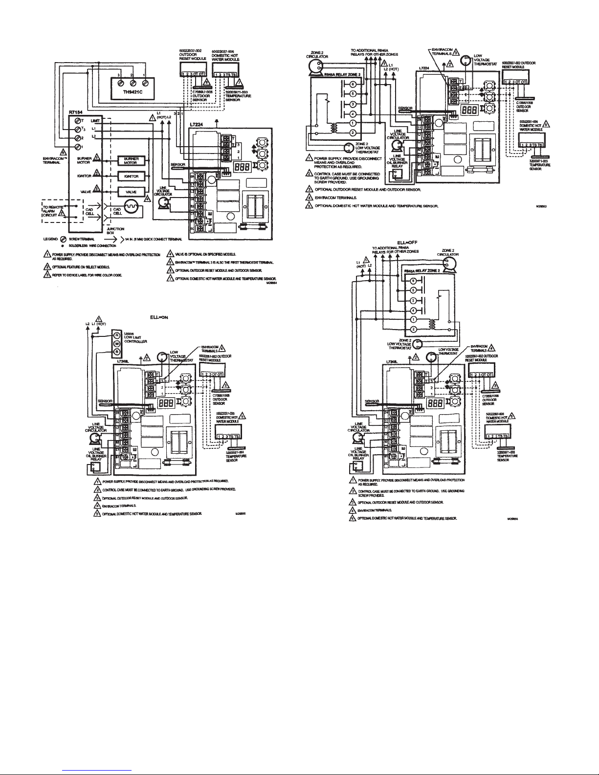
L7224A,C; L7248A,C,L OIL ELECTRONIC AQUASTAT®CONTROLLERS
Fig. 6. L7224A,C multizone system with circulator connections and EnviraCOM™ thermostat.
ig. 6. L7224A,C multizone system with circulator connections.
F
Fig. 6A. L7248 External Low Limit connections.
Figure 6. Honeywell Electrical Schematics for L7224 and L7248 Controls.
D. Install a U.L. listed vent cap where the possibility of a downdraft exists, especially when located on a
hillside or in a wooded area.
XII. WIRING
The internal wiring on package units is completed at the factory. All external wiring must be in accor-
dance with local codes and regulations. Refer to wiring diagram for electrical connections. (Fig. 5 or 6)
Field connections should be protected with a 15 amp fuse. Install a separate fuse disconnect switch
near the unit so power can be shut off for servicing.
Thermostat should be located centrally within the zone to be heated. Zone valves should be installed
on return lines and wired per manufacturer’s specifications.
Fig. 6A. L7248 multizone system with circulator connections.
11
Page 16

Operation
I. START UP
A. Make sure service switch to boiler is off.
B. Make sure boiler has been filled with water until entire system has been purged and desired pressure
obtained.
C. Make sure all manual shut off valves in the gas line are open.
D. Set operating controls at 180°F.
E. Check to make sure that limit switch is set at 205°F.
F. Check burner settings as shown in Table 1. Adjust as required.
G. Bleed off any air in the gas line by attaching a 1/4 NPT nipple and stop-cock to the inlet side of the
Honeywell VR8205A 2008 gas valve. Once a faint smell of gas is noticeable at the fitting, immediately
shut off the valve. Allow the gas to disipate for a period of 5 minutes prior to proceeding to the next step.
H. Apply 120 vac power to the aquastat control. Set thermostat above room temperature to call for heat.
The control will perform a self check routine which consists of full flame sensing. Since the system calls
for heat (step D), the burner will proceed with a 34 second prepurge and then attempt to fire. The burner
will attempt to fire 3 times before going into lockout.
)
II. START UP ADJUSTMENTS
A. Equipment Required
1. CO/CO2 Analyzer
2. Draft Regulator
3. Manometer (Reads in W.C.)
4. Stack Thermometer
B. Adjustment to Gas Pressure Regulator
The manifold pressure should be set to:
120 140 160
Nat. Gas LP Nat. Gas LP Nat. Gas LP
3.5" 2.3" 3.5" 2.3" 3.5" 2.3"
To adjust gas pressure, turn the adjusting screw of the gas pressure regulator out (counterclockwise) to
decrease the pressure. Turn in (clockwise) to increase the pressure. Refer to control specification sheet
supplied with the boiler for location of the gas pressure regulator. The final manifold pressure should not be
more than plus or minus 0.2" water column from the specified pressure. Major changes to the gas flow
should be made by changing the drill size of the burner orifice.
C. Adjustments to the Burner
Allow the burner to operate for at least 15 minutes and then make the following adjustments:
(1) Sampling Hole - Punch a 1/4” hole in the flue pipe between the flue box and the draft regulator. Test
readings should be taken at this point or inspection port. (See page 13)
(2) Draft
ber. This reading must be taken DURING combustion. This “Over-the-Fire” reading must be POSITIVE
pressure. (Refer to Table 1)
(3) Combustion Set-up
MUST be set-up and adjusted during actual field installed conditions.
- Take a draft reading from the inspection port above the burner, directly in the combustion cham-
- Air Band and Head settings shown in the table are approximate. The Burner
12
Page 17
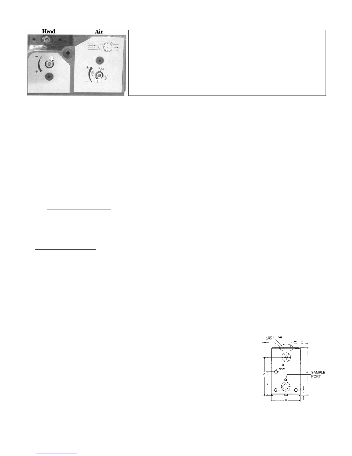
HEAD AND AIR ADJUSTMENT
To access the head and air adjustment, remove the plastic cover
from the rear of the housing, using the supplied 4 mm allen kay. The
eft dial is the head adjustment dial; the right dial is the air adjustment
l
dial. These dials can spin 360° 22 times for the head and 32 times for
the air. Using the same 4 mm allen kay, turn the numbered dials to
the appropriate head setting. These recommended settings are
only approximate settings. Actual field conditions will vary and
require a certified technician with a combustion analyzer to
adjust the burner. OEM settings may differ.
When to adjust the Air
The air shutter is a mechanical shutter. Do NOT over crank the air shutter. You must use an analyzer to
measure the CO
(Carbon Dioxide). General rule: if the CO2is too low, then close the air shutter. If the CO
2
is too high, then open the air shutter. Note: Do NOT set the CO2higher than 9.8% for Natural Gas or
11.5% for LP Gas. If the CO (Carbon Monoxide) is above 100 ppm, there is either too much air or too lit-
tle air. Check the CO
Level and adjust the burner.
2
When to adjust the Head
The retention head is 1/8" inside the tube when the marking reads ‘22’. There is a full 1/2" movement for
the retention disk to move backward (to increase secondary air) or forwards (to decrease secondary air).
NOTE: the head physically moves within the blast tube. Do not over crank the head dial. This move-
ment can also be used to compensate for back pressure in the combustion area, up to 0.3" W.C.
Caution: If this is the case, the flange and the combustion chamber should be completely sealed.
This pressure firing decreases as the firing rate increases. See Graph 1. Note: the burner should be
adjusted while it is firing.
2
Combustion Analysis
You can also take flue gas sampling from the sight fitting/sampling port above the burner. If using
the sampling port, do not
insert the probe into the combustion area too far. Insert probe approximately 1/2”
to 1”. Excessive insertion may cause false readings.
D. Check Out Procedure
After starting the boiler, make certain all controls are working properly before leaving the boiler unattended. Check to be certain that the temperature limit control will shut off the boiler in the event of excessive temperature, by lowering the High Limit set point until the burner shuts off. Reset the High Limit to the
desired temperature setting.
Check main gas valve when closed to be certain there is no leakage. Check all joints for gas leakage.
Use soap solution to check for leakage.
Check the operation of the Ignition System safety shut off device using the following method:
1) Turn gas supply off.
2) Set thermostat above room temperature to call for heat.
3) Time the length of time gas valve stays open. The time should not exceed 4.0 seconds.
III. BURNER SERVICING
A. Burner Components
If a replacement part is necessary, use only the part specified on the burner
parts list in the burner manual. Spec i fy the part number and description when
ordering.
B. Orifice
To increase the firing rate, use only the orifices provided. Any attempt to “drill
out” the orifice will void the warranty for the burner.
C. Set Up
For specific set up procedures refer to the Installer/Serviceman Decal on the boiler or to this manual.
13
Page 18

Maintenance
I. IMPORTANT
ESCAPING GASES ARE DANGEROUS. THE ENTIRE FLUE AND VENTING SYSTEM SHOULD BE
IN SPECT ED AT LEAST ONCE A YEAR BY A QUALIFIED SERVICEMAN.
II. HEAT EXCHANGER
The tubular portions of the heat exchanger should be examined annually for scale and soot accu-
mulation.
Remove scale and soot with a flexible brush and a boiler vacuum cleaner. Be careful not to dam-
age internal refractory insulation of the chamber floor. Properly seal flue box gasketing and bolts.
III. GAS BURNER
A. Thoroughly brush clean the air intake screen of the burner to ensure proper air delivery.
B. Properly seal the burner flange bolts.
IV. LUBRICATION
The blower motor is equipped with sealed bearings and therefore, does not require lubrication.
V. GASKETS
Tighten nuts on water coil to prevent any gasket leaks.
DETERIORATION DUE TO COIL GASKET LEAKS SHALL VOID WARRANTY.
VI. WIRING
Check the electrical wiring for damage of frayed insulation.
HOMEOWNER INFORMATION
Your serviceman is:
Name:
Address:
Phone No.:
14
Page 19

A. General
EVER BURN GARBAGE OR REFUSE IN YOUR HEATING UNIT. NEVER TRY TO IGNITE GAS BY
N
TOSS ING BURNING MATERIAL INTO YOUR BOILER AND NEVER LEAVE COMBUSTIBLE MATERIAL
AROUND IT.
B. Combustion Air Supply
Your burner requires an ample amount of clean air in order to completely and efficiently burn its fuel.
If an ample supply is not available, erratic operation, noisy combustion, and fuel odors in the air may result.
Remember that venting fans or a vented dryer will greatly increase the need for outside air. (See Section
V, part C)
C. Area Around Boiler
The area around the boiler should be kept clean and free of any combustible materials, particularly
oily rags and papers. The boiler should be accessible for ease of service. If burner is shut down for extended period of time, shut off manual fuel supply valve. Brush clean flue passages and vacuum clean unit.
Inspect for leaks at gaskets and fittings. Follow starting procedures to restart.
SERVICE INFORMATION
To avoid unnecessary expense and inconvenience, the boiler and burner should be cleaned and serviced at least once a year by a qualified serviceman. If difficulty occurs, the following should be observed
before calling the serviceman:
A. Check to be sure that the gas line is not shutoff.
B. Check to see if the thermostat setting is above room temperature
C. Check to see if the service switch is in the on position.
DO NOT TAMPER WITH THE UNIT OR ITS CONTROLS.
15
Page 20
TROUBLE SHOOTING GUIDE
ROUBLE: TOO MUCH HEAT
T
SOURCE PROCEDURE CAUSES REMEDY
CIRCULATOR CHECK TO SEE IF OPERATING CIRCULATOR DOES NOT STOP REPAIR
CONTROL IS OPERATING PROPERLY RUNNING
THERMOSTAT CHECK THERMOSTAT SETTINGS THERMOSTAT SET TO HIGH RESET THERMOSTAT
AND CALIBRATION
THERMOSTAT DEFECTIVE REPLACE THERMOSTAT
THERMOSTAT OUT OF RECALIBRATES
CALIBRATION
FLOW VALVE CHECK TO SEE IF FLOW VALVE IS FLOW VALVE DIRTY AND STUCK CLEAN FLOW VALVE
OPERATING PROPERLY
FLOW VALVE DEFECTIVE REPLACE FLOW VALVE
TROUBLE: HIGH NET STACK TEMPERATURES
SOURCE PROCEDURE CAUSES REMEDY
GAS VALVE CHECK MANIFOLD PRESSURE OVER FIRING DUE TO INCREASED CHECK TO ENSURE ORIFICE IS
WITH MANOMETER GAS PRESSURE INSTALLED. TURN GAS VALVE SET
POINT
HEAT EXCHANGER CHECK HEAT EXCHANGER HEAT EXCHANGER FOULED CLEAN HEAT EXCHANGER
SURFACES FOR SOOT AND
FOULING
TROUBLE: INSUFFICIENT DOMESTIC HOT WATER
SOURCE PROCEDURE CAUSES REMEDY
OPERATING CONTROL CHECK OPERATING CONTROL SETTING TO LOW SET OPERATING CONTROL TO
SETTING 180°F
COIL HEAT INSPECT COILS FOR FOULED FLOW RESTRICTION REMOVE RESTRICTION
EXCHANGER SURFACES AND/OR FLOW
RESTRICTIONS FOULED SURFACES ON HEAT CLEAN HEAT EXCHANGER
EXCHANGER SURFACES
TROUBLE: BOILING NOISE IN TOP OF BOILER
SOURCE PROCEDURE CAUSES REMEDY
VENTING CHECK IF SYSTEM IS DEFECTIVE FLOAT VENT REPLACE VENT
PROPERLY VENTED
WATERLOGGED EXPANSION TANK DRAIN TANK
MANUAL VENT REQUIRES VENTING OPEN VENT
IMPROPER VENTING SEE BOILER PIPING SECTION
16
Page 21
ROUBLE: BURNER FIRES BUT PULSATES
T
SOURCE PROCEDURE CAUSES REMEDY
COMBUSTION AIR INSPECT INSTALLATION FOR IMPROPER INSTALLATION PROVIDE OPENINGS THAT
COMBUSTION AIR PROVISIONS COMMUNICATE WITH OUTSIDE
OPEN AIR BAND WIDE AND TAKE IMPROPER ADJUSTMENT ADJUST CO2LEVEL-START WITH
CO2READING AIR BAND WIDE OPEN
GAS SUPPLY BLEED GAS LINE NEW PIPING NOT PURGED OF AIR TIGHTEN ALL FITTINGS
GAS PRESSURE INSTALL A MANOMETER IN THE LOW SUPPLY PRESSURE HAVE GAS COMPANY INCREASE
GAS LINE. PRESSURE SHOULD INCOMING SUPPLY PRESSURE
READ BETWEEN 5.0 AND 11.0 W.C.
TOO MANY LINE RESTRICTIONS INCREASE OVERALL DIAMETER
OF THE GAS LINE
ORIFICE DISCONNECT GAS LINE AND IMPROPERLY SIZED ORIFICE REPLACE WITH ORIFICE
INSPECT ORIFICE SPECIFIED IN MANUAL
NO ORIFICE INSTALLED
HEAT EXCHANGER TAKE DRAFT READING OVER THE PLUGGED HEAT EXCHANGER CLEAN OUT HEAT EXCHANGER
RESTRICTIONS FIRE AND AT THE FLUE BOX. THE
DIFFERENCE SHOULD NOT EXCEED
+.04W.C.
BURNER MOTOR BURNER MOTOR TRIPS ON LINE VOLTAGE BELOW 102V CALL UTILITY COMPANY
OVERLOAD TURN OFF POWER
AND ROTATE BLOWER BY HAND TO FAULTY MOTOR REPLACE MOTOR
CHECK FOR EXCESSIVE DRAG
BLOWER OVERLOADING MOTOR REPLACE BLOWER
DRAFT TAKE A DRAFT READING. DRAFT DOWN DRAFTS INSTALL VENT CAP
SHOULD BE O TO +.10 POSITIVE
PRESSURE OVER FIRE. INSUFFICIENT DRAFT INCREASE DRAFT SETTING
EXCESSIVE DRAFT REDUCE DRAFT SETTINGS,
INSTALL DRAFT REGULATOR
IF NECESSARY
17
Page 22
TROUBLE: BURNER FIRES, BUT THEN FAILS ON SAFETY
SOURCE PROCEDURE CAUSES REMEDY
FLAME CHECK CAD CELL WITH FAULTY FLAME SENSOR CLEAN OR REPLACE
SENSOR OHMMETER. IF MORE THAN 2000
OHMS, CAD CELL IS DEFECTIVE
OR DIRTY
PRIMARY CONTROL AFTER BURNER FIRES OPEN CAD FAULTY PRIMARY CONTROL REPLACE PRIMARY CONTROL
CELL CIRCUIT IF FLAME LOOK
GOOD, IF BURNER CONTINUES
TO OPERATE FAULT IS IN
PRIMARY CONTROL
TROUBLE: BURNER FIRES THEN LOSES FLAME
SOURCE PROCEDURE CAUSES REMEDY
POOR FIRE INSPECT FOR FLAME STABILITY UNBALANCED FIRE ADJUST BURNER INSERTION
DEPTH
EXCESSIVE DRAFT REDUCE DRAFT SETTING
INSUFFICIENT DRAFT INCREASE DRAFT
TO LITTLE COMBUSTION AIR INCREASE COMBUSTION AIR
COMBUSTION AIR REDUCE COMBUSTION AIR TOO MUCH COMBUSTION AIR CLOSE AIR BAND TO RAISE CO
SUPPLY TO PROPER LEVELS
EXCESSIVE DRAFT TAKE A DRAFT READING DRAFT INCORRECT DRAFT SETTING REDUCE DRAFT SETTING
SHOULD BE O TO +.02 POSITIVE INSTALL SECOND DRAFT
PRESSURE OVER THE FIRE REGULATOR IF NECESSARY
2
18
Page 23
ROUBLE: INSUFFICIENT HEAT
T
SOURCE PROCEDURE CAUSES REMEDY
CIRCULATOR CHECK IF CIRCULATOR IS COUPLING WORN OR BROKEN REPLACE COUPLING
OPERATIONAL
PUMP BINDING REPLACE PUMP
CIRCULATOR MOTOR BURNED OUT REPLACE CIRCULATOR MOTOR
WIRING FROM OPERATING REPAIR WIRING
CONTROL DEFECTIVE
OPERATING CONTROL DEFECTIVE REPAIR OR REPLACE OPERATING
CONTROL
CHECK IF CIRCULATOR IS CIRCULATOR TO SMALL REPLACE WITH PROPER
CORRECT SIZE CIRCULATOR
CHECK VOLTAGE TO CIRCULATOR INSUFFICIENT VOLTAGE CALL UTILITY COMPANY
THERMOSTAT CHECK THERMOSTAT SETTINGS SETTINGS TO LOW INCREASE SETTING
CHECK THERMOSTAT LOCATION BAD LOCATION DUE TO HEAT MOVE THERMOSTAT TO A
BUILD UP BETTER LOCATION
CHECK THERMOSTAT LOCATION OUT OF CALIBRATION RECALIBRATES
FLOW VALVE CHECK FLOW VALVE FOR FLOW VALVE NOT OPENING FULLY CLEAN OR REPLACE FLOW
STICKING IN PARTIALLY CLOSED VALVE
POSITION
RADIATION CHECK RADIATORS FOR AIR RADIATORS AIR BOUND BLEED RADIATORS
CHECK TO SEE IF RADIATORS ARE RADIATORS INADEQUATE INSTALL ADEQUATE RADIATION
PROPERLY SIZED
BOILER DETERMINE STRUCTURE HEAT BOILER TO SMALL ADDITIONAL HEATING CAPACITY
LOAD REQUIRED
TANKLESS COIL CHECK USAGE OF DOMESTIC HOT DEMAND TO LARGE INSTALL FLOW REGULATOR
WATER
ADDITIONAL BOILER CAPACITY
REQUIRED
PIPING CHECK TO SEE IF PIPING IS PIPING INADEQUATE INSTALL ADEQUATE PIPING
PROPERLY SIZED
HEAT EXCHANGER CHECK HEAT EXCHANGER FOR INSUFFICIENT HEAT TRANSFER CLEAN HEAT EXCHANGER
SOOT OR SCALE ACCUMULATION
BURNER INCREASE GAS MANIFOLD DECREASE IN GAS LINE PRESSURE CHECK WITH GAS COMPANY FOR
PRESSURE BY OPENING UP THE CHANGES IN SERVICE
GAS VALVE
CHECK FOR LEAKS UPSTREAM OF
BURNER
19
Page 24
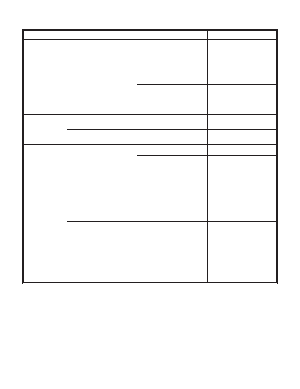
ROUBLE: BURNER DOES NOT START
T
SOURCE PROCEDURE CAUSES REMEDY
THERMOSTAT CHECK THERMOSTAT SETTINGS THERMOSTAT SET TO LOW TURN THERMOSTAT UP
THERMOSTAT ON “OFF” OR “COOL” SWITCH TO HEAT
JUMPER TT TERMINALS ON OPEN THERMOSTAT WIRES REPAIR OR REPLACE WIRES
AQUASTAT
LOOSE THERMOSTAT TIGHTEN CONNECTIONS
CONNECTORS
FAULTY THERMOSTAT REPLACE THERMOSTAT
THERMOSTAT NOT LEVEL LEVEL THERMOSTAT
DIRTY THERMOSTAT CONTACTS CLEAN CONTACTS
CIRCUIT OVERLOADS CHECK BURNER MOTOR BURNER MOTOR TRIPPED ON PUSH RESET BUTTON
OVERLOAD SWITCH OVERLOAD
CHECK PRIMARY CONTROL PRIMARY TRIPPED ON SAFETY RESET SAFETY SWITCH
SAFETY SWITCH
POWER CHECK BOILER DISCONNECT SWITCH OPEN CLOSE SWITCH
SWITCH AND MAIN DISCONNECT
SWITCH TRIPPED BREAKER OR BLOWN RESET BREAKER OR REPLACE
FUSE FUSE
PRIMARY CONTROL CHECK FOR VOLTAGE AT THE LIMIT CONTROL SWITCH OPEN CHECK LIMIT SETTING
BURNER BETWEEN THE BLACK
AND WHITE WIRES JUMPER TERMINALS-IF BURNER
STARTS REPLACE CONTROL
OPEN CIRCUIT BETWEEN LIMIT REPAIR CIRCUIT
CONTROL AND DISCONNECT
SWITCH
LOW ONE VOLTAGE OR POWER CALL UTILITY COMPANY
CHECK FOR VOLTAGE AT THE DEFECTIVE CONTROL REPLACE CONTROL
BURNER BETWEEN THE ORANGE
AND WHITE WIRES. NO VOLTAGE
INDICATES A FAULTY CONTROL
BURNER MOTOR CHECK FOR VOLTAGE PUMP SEIZED TURN OFF POWER TO BURNER.
BURNER MOTOR LEADS ROTATE BY HAND, CHECK FOR
EXCESSIVE DRAG. REPLACE
BLOWER WHEEL BINDING FUEL UNIT OR BLOWER WHEEL
BURNER MOTOR DEFECTIVE REPLACE BURNER MOTOR
20
Page 25
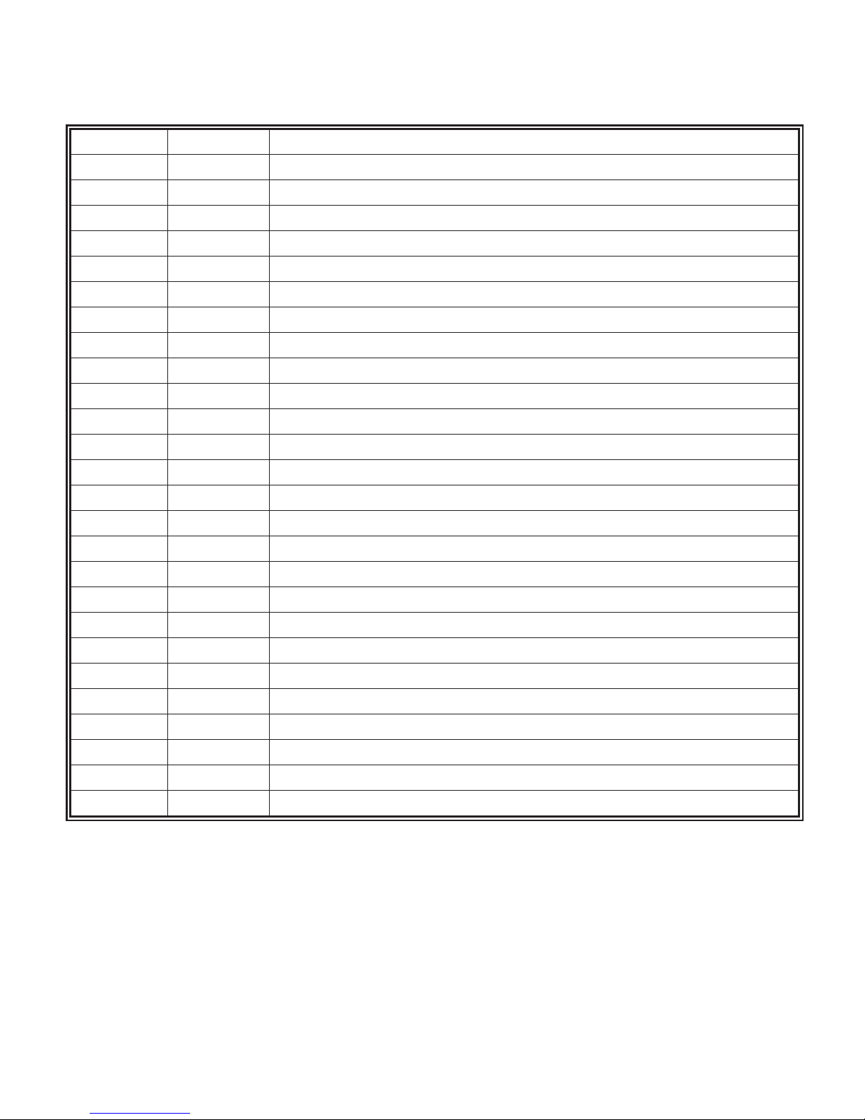
Parts List CWL-GS
(Designate boiler and burner model numbers on all orders.)
Item No. Part No. Description
1 542241 Heatwise SU-2A Gas Burner
2 542243 Heatwise SU-2A DV Gas Burner
3 535030 007 Circulator Pump
4 552102 Aquastat Control L7224C (on CWL GS/CWL GS DV)
5 552116 Aquastat Control L7248 (on NCWL GS/NCWL GS DV)
6 575020 Relief Valve (3/4" Male)
7 559560 Altitude Gauge 1/4" x 2-1/2" Round
8 481005 Coil Gasket (TDR)
9 530247 TDR5L Coil with Gasket-Cartoned
10 229151 Blank Coil Plate with 1/8" and 3/4" Tapping
11 190399 Baffles (CWL, 10 required)
12 190401 Flue Box (Top Vent)
13 199991 Flue Box (Rear Vent with Regulator)
14 337135 Gasket Material (25' Roll)
15 337799 Cerablanket Floor Insulation
14 337800 Ceraform Floor Board 19 x 19
542260 LP Orifice 15/64
542261 Natural Gas Orifice 19/64
21
Page 26
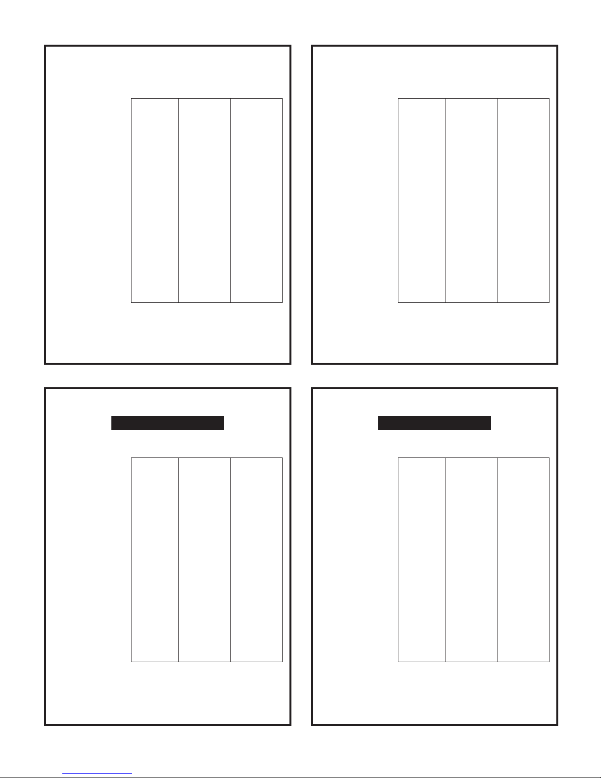
INSTALLER/SERVICEMAN
Fixed Pressure and Variable Orifice
INSTALLER/SERVICEMAN
Fixed Pressure and Variable Orifice
odel Number
M
Burner Type Heat Wise Heat Wise Heat Wise
Burner Model SU-2A SU-2A SU-2A
Fuel Nat. Gas Nat. Gas Nat. Gas
Orifice 15/64" 1/4" 19/64"
Max Inlet Pressure 11" 11" 11"
Min Inlet Pressure 5" 5" 5"
Manifold Pressure 3.5" 3.5" 3.5"
Head Position 11 11 11
Air Shutter 12.50 15.00 20.75
Draft Over Fire + 0.04" + 0.06" + 0.08"
Draft In Stack -0.02" -0.02" -0.02"
CO2 Reading 9.0% 9.0% 9.0%
Above settings are approximate. Final adjustments to be made
with proper test equipment. See installation/service manual for
detailed information.
CWL-GS-120 CWL-GS-140 CWL-GS-160
_________________________
_________________________
_________________________
_________________________
_________________________
_________________________
_________________________
_________________________
_________________________
_________________________
_________________________
NOTICE
odel Number
M
Burner Type Heat Wise Heat Wise Heat Wise
Burner Model SU-2A SU-2A SU-2A
Fuel LP Gas LP Gas LP Gas
Orifice 15/64" 1/4" 19/64"
Max Inlet Pressure 11" 11" 11"
Min Inlet Pressure 4.5" 4.5" 4.5"
Manifold Pressure 2.3" 2.3" 2.3"
Head Position 11 11 11
Air Shutter 14.50 17.00 20.25
Draft Over Fire + 0.04" + 0.06" + 0.08"
Draft In Stack -0.02" -0.02" -0.02"
CO2 Reading 11% 11% 11%
Above settings are approximate. Final adjustments to be made
with proper test equipment. See installation/service manual for
detailed information.
CWL-GS-120 CWL-GS-140 CWL-GS-160
_________________________
_________________________
_________________________
_________________________
_________________________
_________________________
_________________________
_________________________
_________________________
_________________________
_________________________
NOTICE
INSTALLER/SERVICEMAN
CWL-GS DIRECT VENT
Fixed Pressure and Variable Orifice
Model Number CWL-GS-120DV CWL-GS-140DV CWL-GS-160DV
Burner Type Heat Wise Heat Wise Heat Wise
Burner Model SU-2A SU-2A SU-2A
Fuel Nat. Gas Nat. Gas Nat. Gas
Orifice 15/64" 1/4" 19/64"
Max Inlet Pressure 11" 11" 11"
Min Inlet Pressure 5" 5" 5"
Manifold Pressure 3.5" 3.5" 3.5"
Head Position 11 11 11
Air Shutter 12.50 15.00 20.75
Draft Over Fire + 0.10" + 0.14" + 0.18"
Draft In Stack -0.06" -0.08" -0.10"
CO2 Reading 9.0% 9.0% 9.0%
Above settings are approximate. Final adjustments to be made
with proper test equipment. See installation/service manual for
detailed information.
_________________________
_________________________
_________________________
_________________________
_________________________
_________________________
_________________________
_________________________
_________________________
_________________________
_________________________
NOTICE
INSTALLER/SERVICEMAN
CWL-GS DIRECT VENT
Fixed Pressure and Variable Orifice
Model Number CWL-GS-120DV CWL-GS-140DV CWL-GS-160DV
Burner Type Heat Wise Heat Wise Heat Wise
Burner Model SU-2A SU-2A SU-2A
Fuel LP Gas LP Gas LP Gas
Orifice 15/64" 1/4" 19/64"
Max Inlet Pressure 11" 11" 11"
Min Inlet Pressure 4.5" 4.5" 4.5"
Manifold Pressure 2.3" 2.3" 2.3"
Head Position 11 11 11
Air Shutter 15.50 17.75 21.00
Draft Over Fire + 0.10" + 0.14" + 0.18"
Draft In Stack -0.06" -0.08" -0.10"
CO2 Reading 11.0% 11.0% 11.0%
Above settings are approximate. Final adjustments to be made
with proper test equipment. See installation/service manual for
detailed information.
_________________________
_________________________
_________________________
_________________________
_________________________
_________________________
_________________________
_________________________
_________________________
_________________________
_________________________
NOTICE
22
Page 27
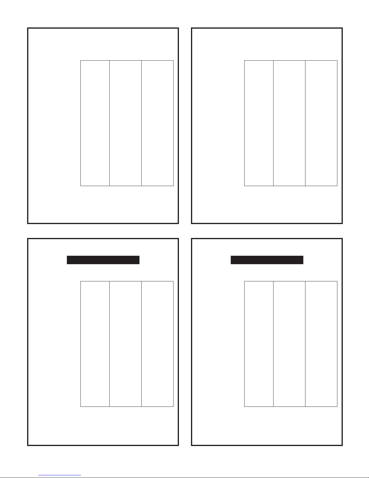
INSTALLER/SERVICEMAN
Fixed Pressure and Variable Orifice
INSTALLER/SERVICEMAN
Fixed Pressure and Variable Orifice
odel Number
M
Burner Type Heat Wise Heat Wise Heat Wise
Burner Model SU-2A SU-2A SU-2A
Fuel Nat. Gas Nat. Gas Nat. Gas
Orifice 15/64" 1/4" 19/64"
Max Inlet Pressure 11" 11" 11"
Min Inlet Pressure 5" 5" 5"
Manifold Pressure 3.5" 3.5" 3.5"
Head Position 11 11 11
Air Shutter 12.50 15.00 20.75
Draft Over Fire + 0.04" + 0.06" + 0.08"
Draft In Stack -0.02" -0.02" -0.02"
CO2 Reading 9.0% 9.0% 9.0%
Above settings are approximate. Final adjustments to be made
with proper test equipment. See installation/service manual for
detailed information.
NCWL-GS-120 NCWL-GS-140 NCWL-GS-160
_________________________
_________________________
_________________________
_________________________
_________________________
_________________________
_________________________
_________________________
_________________________
_________________________
_________________________
NOTICE
odel Number
M
Burner Type Heat Wise Heat Wise Heat Wise
Burner Model SU-2A SU-2A SU-2A
Fuel LP Gas LP Gas LP Gas
Orifice 15/64" 1/4" 19/64"
Max Inlet Pressure 11" 11" 11"
Min Inlet Pressure 4.5" 4.5" 4.5"
Manifold Pressure 2.3" 2.3" 2.3"
Head Position 11 11 11
Air Shutter 14.50 17.00 20.25
Draft Over Fire + 0.04" + 0.06" + 0.08"
Draft In Stack -0.02" -0.02" -0.02"
CO2 Reading 11% 11% 11%
Above settings are approximate. Final adjustments to be made
with proper test equipment. See installation/service manual for
detailed information.
NCWL-GS-120 NCWL-GS-140 NCWL-GS-160
_________________________
_________________________
_________________________
_________________________
_________________________
_________________________
_________________________
_________________________
_________________________
_________________________
_________________________
NOTICE
INSTALLER/SERVICEMAN
NCWL-GS DIRECT VENT
Fixed Pressure and Variable Orifice
Model Number NCWL-GS-120DV NCWL-GS-140DV NCWL-GS-160DV
Burner Type Heat Wise Heat Wise Heat Wise
Burner Model SU-2A SU-2A SU-2A
Fuel Nat. Gas Nat. Gas Nat. Gas
Orifice 15/64" 1/4" 19/64"
Max Inlet Pressure 11" 11" 11"
Min Inlet Pressure 5" 5" 5"
Manifold Pressure 3.5" 3.5" 3.5"
Head Position 11 11 11
Air Shutter 12.50 15.00 20.75
Draft Over Fire + 0.10" + 0.14" + 0.18"
Draft In Stack -0.06" -0.08" -0.10"
CO2 Reading 9.0% 9.0% 9.0%
Above settings are approximate. Final adjustments to be made
with proper test equipment. See installation/service manual for
detailed information.
_________________________
_________________________
_________________________
_________________________
_________________________
_________________________
_________________________
_________________________
_________________________
_________________________
_________________________
NOTICE
INSTALLER/SERVICEMAN
NCWL-GS DIRECT VENT
Fixed Pressure and Variable Orifice
Model Number NCWL-GS-120DV NCWL-GS-140DV NCWL-GS-160DV
Burner Type Heat Wise Heat Wise Heat Wise
Burner Model SU-2A SU-2A SU-2A
Fuel LP Gas LP Gas LP Gas
Orifice 15/64" 1/4" 19/64"
Max Inlet Pressure 11" 11" 11"
Min Inlet Pressure 4.5" 4.5" 4.5"
Manifold Pressure 2.3" 2.3" 2.3"
Head Position 11 11 11
Air Shutter 15.50 17.75 21.00
Draft Over Fire + 0.10" + 0.14" + 0.18"
Draft In Stack -0.06" -0.08" -0.10"
CO2 Reading 11.0% 11.0% 11.0%
Above settings are approximate. Final adjustments to be made
with proper test equipment. See installation/service manual for
detailed information.
_________________________
_________________________
_________________________
_________________________
_________________________
_________________________
_________________________
_________________________
_________________________
_________________________
_________________________
NOTICE
23
Page 28

P/N 595830
100-2/10
MET-235
 Loading...