

Thermo Dynamics CWL, NCWL, CWLDV Installation, Operation & Maintenance Manual
CWL Series - LE Edition
Models CWL, NCWL, CWLDV
Installation
Operation
Maintenance
Manual
Thermo-Dynamics Boiler Company
ROUTE 61 • P.O. BOX 325 • SCHUYLKILL HAVEN, PA 17972
TEL (570) 385-0731 • FAX (570) 385-5304
WEB www.thermodynamicsboiler.com • EMAIL sales@thermodynamicsboiler.com
www.thermodynamicsboiler.com

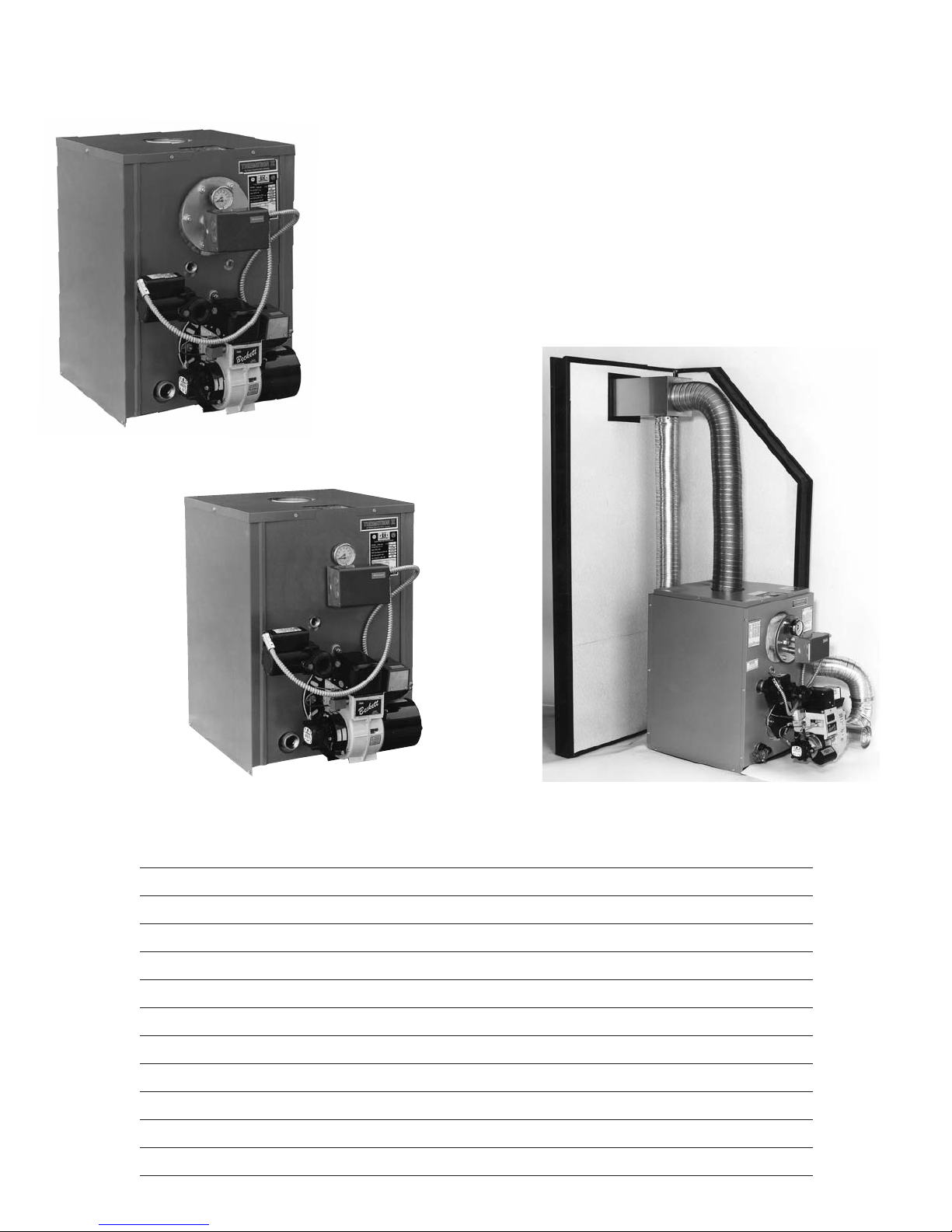
CWL-LE
Product Features
• ASME Coded Boiler Registered with National Board
• Factory Mounted/Wired Burner and Controls
• Fully Insulated Heat Exchanger with Powder-Coated Cabinet
• Packaged with Standard Five Gallon per Minute Tankless Coil
(Domestic Hot Water)
• NCWL Model Available Without Tankless Coil
• Equipped with Triple Aquastat, Circulator, and Temperature /
Altitude Gauge
• Provided With Additional Nozzles to Achieve a Variety of Heat Inputs
• Provided with a Lifetime Limited Warranty
• Available as Direct Vent and Rear Vent Models
NCWL
Service Policy 2
Homeowner Information 3
Read This First 4
Model Specifications 5
Installation 6
Operation 13
Maintenance 16
Trouble Shooting 17
Parts List 24
Preliminary Settings 25
Wiring Diagrams 27
Burner Service Records Inside Back Cover
CWL-DV
Contents

Service Policy
Congratulations on the purchase of your boiler. At Thermo-Dynamics Boiler
Company we pride ourselves on the design and construction of our product. Our
intent is to furnish you with a high quality appliance that will provide you and your
family with years of trouble free service.
In order to maintain peak performance of your boiler, it is recommended that
the burner/boiler be serviced annually, preferably prior to the onset of the winter
heating season. Servicing of your appliance must be performed by a qualified heating technician. You should utilize a qualified heating technician familiar with your
installation to manage your heater and perform periodic maintenance. Proper care
and maintenance of your boiler will allow you to enjoy the benefits of your new purchase as well as extend its long useful life.
In the event that your serviceman encounters difficulty with the boiler, he/she
shall contact the distributor from which the product was purchased. The distributor,
in turn, will contact the Thermo-Dynamics sales representative for your area. By
adhering to this protocol, Thermo-Dynamics will provide you with responsive and
unparalleled service. We realize the importance that our product means to you and
your family and our goal is to get your heater up and running as quickly as possible.
Thank you for purchasing the Thermo-Dynamics boiler. Again, it is our intent
to provide you with a high quality trouble free product that will be part of your family for many years to come. Please consider Thermo-Dynamics Boiler Company in
the future for all of your home heating needs.
2

HOMEOWNER INFORMATION
Heating Contractor:
Address:
Phone No.:
A) General
Installation and service is to be done only by a certified and qualified technician.
Never burn garbage or refuse in your boiler or leave combustible material around it. Do not allow the fuel
tank to run out of oil. The fuel tank should be kept full during the summer, or periods of non-use, to prevent condensation of moisture on the inside of the tank.
B) Combustion Air Supply
The burner requires an ample amount of clean combustion air to burn efficiently. If ample supply is not
available erratic, noisy combustion will result. Under these conditions fuel odors may occur. The installation and use of venting fans (anywhere in the house) or a vented dryer will greatly increase the need
for outside air.
C) Area Around Boiler
The area around the boiler must be kept clean and free of any combustible materials, particularly oily rags
or papers. The boiler must be accessible for service.
D) Annual Tune-Up
The boiler should be serviced once a year, ideally just prior to the heating season. The tune-up is to be
done by a qualified technician following procedures listed under Maintenance in this manual
E) If Boiler Doesn’t Start:
1) Check if there is fuel in the tank.
2) Is thermostat setting above room temperature.
3) Is service switch in the “on” position.
Should there be a problem with operation of the boiler, call a qualified service technician. Do not
tamper with the unit or controls.
3

Read This First
1. Installer must be a trained, experienced technician and should read all instructions before
installation.
2. Inspect the boiler, jacket and all components to be sure damage has not occurred in shipment. If
damage is evident, do not install the boiler. Contact your distributor immediately. A claim must be
filed with the freight carrier that transported the boiler from the factory to the distributor.
3. Disconnect power supply before connecting wiring.
4. Refer to local codes for oil burning equipment, for recommended installation practice. You will
need to be familiar with NFPA International Standard 31, “Standard for the Installation of Oil
Burning Equipment”.
5. A complete heat loss calculation is necessary to choose the proper size unit to install. The boiler
should be sized to within 25% of the actual heat loss of the structure. Over sizing will result in
short cycling and inefficient operation.
6. When moving the boiler, do not push against the jacket or burner. Damage will result.
7. If the boiler is vented to a chimney, be certain the chimney is clean and free of obstructions. The
chimney must be masonry with tile lining or metal insulated with a stainless steel surface. The
chimney must be properly sized. Draft requirements are essential for safe and proper operation of
the boiler.
8. If the boiler is connected to a venting device, make sure that it is listed by a recognized testing
service. Follow the venting device manufacturer’s installation instructions. Verify that the venting
device installation complies with the recommendations of the manufacturer and local and state
codes.
9. Conduct a thorough checkout when installation is complete. Check for indications of leaks and
make sure that no material is left adjacent to the boiler.
10. The use of low sulfur No. 2 heating oil is highly recommended.
11. Modification, substitution or elimination of factory equipped, supplied or specified components
may result in property damage, personal injury or the loss of life.
12. The following definitions apply to potential hazards noted in this manual.
DANGER: Indicates a hazardous situation which if not avoided will result in death or serious injury.
WARNING: Indicates a hazardous situation which if not avoided could result in death or serious
injury.
CAUTION: Indicates a hazardous situation which if not avoided, may result in a minor injury. It may
also warn against unsafe practices that may result in minor injury or damage to equipment.
NOTICE: Indicates that special attention to information is required. Not related to personal injury or
property damage.
4
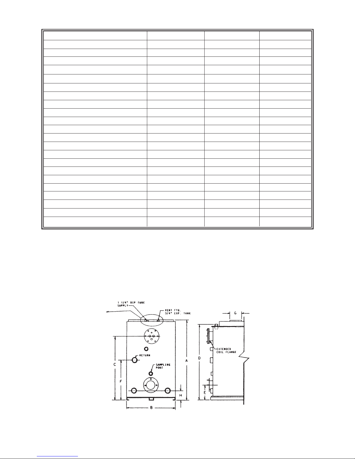
Model Specifications CWL 85 CWL 100 CWL 110
HEATING CAPACITY 101,000 118,000 127,000
IBR NET RATING 88,000 103,000 110,000
INPUT 119,000 140,000 154,000
FIRING RATE .85 1.00 1.10
CHIMNEY SIZE 8 x 8 x 15 8 x 8 x 15 8 x 8 x 15
OVER FIRE PRESSURE W.C. 0-+.05 0-+.08 0-+.10
WATER CONTENT 15 GAL. 15 GAL. 15 GAL.
COIL CAPACITY 5 GAL. 5 GAL. 5 GAL.
A. JACKET HEIGHT* 29-1/2 29-1/2 29-1/2
B. JACKET WIDTH 21 21 21
. COIL SUPPLY HEIGHT 22 22 22
C
D. SUPPLY HEIGHT (HYDRONIC) 27-1/2 27-1/2 27-1/2
E. BURNER HEIGHT 7-7/8 7-7/8 7-7/8
F. HYDRONIC RETURN HEIGHT 15-1/2 15-1/2 15-1/2
G. FLUE PIPE DIA. 5 5 5
H. WASHOUT (ALT. RETURN HEIGHT) 3-1/2 3-1/2 3-1/2
I. JACKET DEPTH (INCL. FLANGE) 22 22 22
DEPTH FRONT TO REAR W/BURNER 30-3/4 30-3/4 30-3/4
HYDRONIC SUPPLY 1-1/4 1-1/4 1-1/4
HYDRONIC RETURN SIZE 1-1/4 1-1/4 1-1/4
WASHOUT (ALT. RETURN) 1-1/4 (2) 1-1/4 (2) 1-1/4 (2)
AFUE RATING - W/DAMPER 86.0 84.9 84.1
AFUE RATING - W/O DAMPER 84.3 83.2 82.1
*Specifications apply to CWL-LE, NCWL and CWL-DV except when using REAR FLUE KIT, jacket height increases by
4-1/4 inches
Figure 1 - Model Dimensions
“0” Clearance Sides and Back
Approved for combustible Floors
5

Installation
I GENERAL
This hot water steel boiler is a high quality oil fired heating units. The installation of the boiler shall be
in accordance with state and local regulations. Refer to local Installation Codes for Oil Burning
Equipment, for recommended installation practice.
II FREIGHT CLAIMS
All units must be inspected for damage upon arrival. Concealed damage claims should be filed immediately against the carrier by the consignor. The carrier is responsible for taking prompt action on all claims.
III SIZING
Replacement boilers should not be sized from the firing rate of the old boiler; a DOE sponsored study
indicated 65% of the heating units in U.S. homes are substantially oversized. A complete heat loss calculation of the structure is necessary to choose the proper size unit to install. The boiler should be sized
to within 25% of the actual calculated heat loss of the structure. Over sizing will result in short cycling
and inefficient operation.
IV BOILER LOCATION
A) Boiler to be installed in a level position with clearances in accordance with NFPA 31 Table
10.6.1.
STANDARD CLEARANCES
Front 0" (leave 12" to access burner/control)
Sides 0"
Rear 0"
Chimney Connector 18"
Top 0" (leave 18" for cleaning)
Floor: Approved for installation on combustible flooring
B) Reduced clearance installations shall comply with NFPA 31 Table 10.6.2.
C) To move the unit, push against the flue box or skids. Pushing or pulling the jacket or burner
will result in damage.
D) Be sure to level the unit by inserting shims under the elevated base.
E) CWL Series - LE rear flue kit with built-in draft regulator.
6

V. AIR FOR COMBUSTION AND VENTILATION - CHIMNEY VENT APPLICATIONS
The unit must be installed where provisions exist for combustion and ventilation air. Ordinarily, provisions may be furnished by the following methods.
A) Utility Room or Closet
In buildings of tight construction, including most modern homes, you should provide an opening, connecting to a well ventilated attic, crawl space or directly with the outdoors. The opening should have a
minimum free area of 1 square inch per 1,000 Btu per hour of total input for all appliances in the enclosure and should terminate below the burner level. Boilers installed in confined areas or closets must have
two ventilation openings in the closet door. Each opening should have a free area of not less than 1 square
inch per 1000 Btu (140 square inch per US gph) of the total input for all appliances in the enclosure. One
opening located near the top of enclosure and one near the bottom.
B. Basement
1. When a boiler is installed in a full basement, infiltration is normally adequate to provide air
for combustion.
2. In buildings of tight construction when the basement windows are weather stripped, one opening to a well ventilated attic or with the outdoors should be provided. The opening should have a minimum free area of 1 square inch per 1,000 Btu per hour of total input for all appliances in the enclosure.
C. Special Conditions
When a boiler is located in an area where exhaust fans, kitchen ventilation systems, clothes dryers, or fireplaces may create conditions of unsatisfactory combustion or venting, special provisions
should be made for additional air for combustion, as specified by local authority.
VI. AIR FOR COMBUSTION AND VENTILATION - DIRECT VENT APPLICATIONS
A) VENTING SYSTEM
CAUTION: EXTERNAL VENT SURFACES ARE HOT.
NOTE: USE ONLY THE ETL LISTED VENTING SYSTEM COMPONENTS SUPPLIED WITH
THE TV-175 DIRECT VENT KIT.
SURFACE DISCOLORATION OF THE BUILDING MAY OCCUR DUE TO IMPROPER BOILER/BURNER ADJUSTMENT. THERMO DYNAMICS BOILER COMPANY WILL NOT ACCEPT
ANY LIABILITY FOR SUCH DISCOLORATION.
Install TV-175 Direct Vent Kit in accordance with installation instructions provided with the kit.
7
VII JACKET AND TRIM ASSEMBLY
A. Knock Down Boiler
1. Jacket Assembly - Unpack the jacket parts being careful not to damage the finish. Piping and acces-
sories are installed after the jacket is in place. Assemble the jacket as shown in Figure 5.
2. Trim Assembly
a. Install the safety relief valve in the 3/4" tapping in the top of the boiler. The relief valve should be
piped to a safe place of discharge.
b. Install the limit control in the 3/4" fitting provided in the tankless coil plate.
c. Install the altitude/temperature gauge in the 1/4" fitting provided in the coil plate.
B. Packaged Boiler
Controls and burner are installed and prewired at the factory. Install Relief Valve as noted in Section 2a
(Trim Assembly).
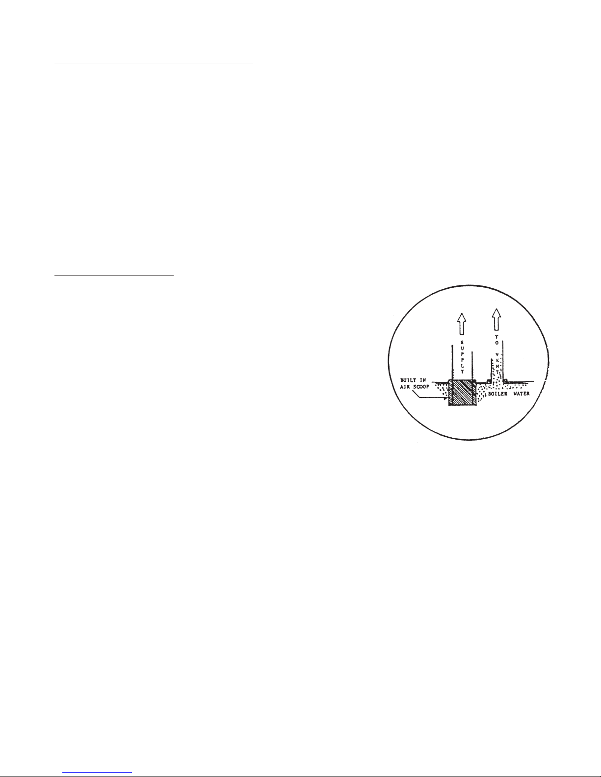
VIII BOILER PIPING
This style of boiler is equipped with a built in “Air Scoop System Figure 2.” This feature allows quiet air free operation of your hot water
system by assuring the removal of noisy air pockets. The supply line
or Riser tapping in the top of the boiler extends approximately 1"
below the top or waterline of the boiler, thus allowing only air free
water to enter the supply to the heating system. The air trapped in
the top of the boiler is then purged through a 3/4" vent tapping to be
released with an (1) automatic float vent (2) a manual vent or (3)
piped into a conventional type expansion tank.
Relief valve discharges and drain valve piping should be piped to a safe
place of discharge. All plugs and water connections should be checked
for leaks upon installation and annually.
FIGURE 2
BUILT-IN AIR SCOOP
8
 Loading...