

Thermocold MEX VS 15 RH, MEX VS 18 RH, MEX VS 16 RH, MEX VS 19 RH, MEX VS 112 RH User Manual
...
CONTROLLER MANUAL FOR CHILLERS AND
INVERTER AIR/WATER HEAT PUMPS WITH
AXIAL FANS
MANUALE DEL CONTROLLO
MEX VS 15 RH / MEX VS 16 RH
MEX VS 18 RH /
MEX VS 19 RH
MEX VS 112 RH
/MEX VS 112T RH
MEX VS 115 RH
/ MEX VS 115T RH
Cod.
MCO14124H7800-02
CONTROLLER MANUAL
MEX VS 15 RH / MEX VS 16 RH
MEX VS 18 RH / MEX VS 19 RH
MEX VS 112 RH /MEX VS 112T RH
MEX VS 115 RH / MEX VS 115T RH
Cod. MCO14124H7820-02
Questo manuale è stato creato per scopo informativo. La ditta declina ogni responsabilità per i risultati di una progettazione o di una installazione basata sulle spiegazioni e le specifiche
tecniche riportate in questo manuale. E’ inoltre vietata la riproduzione anche parziale sotto qualsiasi forma dei testi e delle figure contenute in questo manuale.
Manuale in lingua originale

Controller for MEX VS Chillers and inverter air / water heat pumps with axial fans
1
INDEX
1 CONSERVATION OF THE MANUAL .......................................................................................................................................... 3
1.1 GRAPHIC SYMBOLS ................................................................................................................................................................. 3
2 PERMITTED USES ................................................................................................................................................................... 3
3 GENERAL SAFETY RULES ......................................................................................................................................................... 3
3.1 PERSONAL SAFETY EQUIPMENTS ........................................................................................................................................... 3
3.2 WORKERS’ HEALTH AND SAFETY ............................................................................................................................................ 3
4 PURPOSES AND CONTENTS OF THE MANUAL ......................................................................................................................... 5
5 USER’S INTERFACE - CONTROLER ........................................................................................................................................... 5
5.1 MENU STRUCTURE DIAGRAM ................................................................................................................................................ 5
5.2 ANALOG INPUT MENU ............................................................................................................................................................ 6
5.3 PARAMETERS CATEGORIES .................................................................................................................................................... 6
5.4 SETPOINT ADJUSTABLE BY THE USER...................................................................................................................................... 6
5.5 DISPLAY .................................................................................................................................................................................. 7
5.6 LED ......................................................................................................................................................................................... 7
5.7 INPUT/OUTPUT (I/O) PORTS ................................................................................................................................................... 7
6 DYNAMIC SET-POINT ADJUSTMENT ....................................................................................................................................... 8
7 SET-POINT ADJUSTMENT FROM 0-10V INPUT ........................................................................................................................ 8
8 CIRCULATOR .......................................................................................................................................................................... 9
8.1 OPERATION BY MEAN OF THERMOREGULATOR (DEFAULT) ..................................................................................................... 9
8.2 OPERATION BY THERMOREGULATOR WITH PERIODIC ACTIVATION .................................................................................... 10
8.3 OPERATION WITH ACTIVE ELECTRIC HEATER ....................................................................................................................... 10
8.4 CONTINUOUS OPERATION ................................................................................................................................................... 10
8.5 PROPORTIONAL ADJUSTMENT OF THE PUMP ...................................................................................................................... 10
8.6 PURGING THE SYSTEM .......................................................................................................................................................... 11
9 HEAT DISSIPATION FAN MOTOR CONTROL .......................................................................................................................... 11
9.1 FAN SPEED CONTROL IN COOLING MODE ............................................................................................................................ 11
9.2 FAN SPEED CONTROL IN HEATING MODE ............................................................................................................................. 12
10 CONTROL FUNCTIONS ...................................................................................................................................................... 12
10.1 ALARM WARNING ................................................................................................................................................................ 12
10.2 ANTIFREEZE PROTECTION ELECTRIC HEATERS (WHEN THE KA ACCESSORY IS PRESENT) ...................................................... 12
10.3 ACTIVATION OF SANITARY (DOMESTIC) HOT WATER PRODUCTION .................................................................................... 12
10.3.1 SENSOR MEMORIZATION IN HEATING MODE .............................................................................................................. 13
10.4 HEATING MODE ON SANITARY ACCUMULATION ................................................................................................................. 14
10.5 REMOTE FUNCTIONS ............................................................................................................................................................ 15
10.5.1 ON/OFF ......................................................................................................................................................................... 15
10.5.2 SUMMER/WINTER MODE COMMUTATION ................................................................................................................. 15
10.5.3 SANITARY MODE CALL FROM DIGITAL INPUT .............................................................................................................. 15
10.6 REMOTE SENSOR FOR THE WATER TEMPERATURE OF THE PLANT CIRCUIT ......................................................................... 16
10.7 AUXILIARY ELECTRIC HEATER................................................................................................................................................ 16
10.7.1 PLANT CIRCUIT ELECTRIC HEATER ................................................................................................................................ 16
10.7.2 AUXILIARY ELECTRIC HEATER OF THE PLANT IN DEFROST CYCLE ................................................................................. 16
10.7.3 ELECTRIC HEATER OF SANITARY WATER PRODUCTION ............................................................................................... 17
10.7.4 A UNIQUE AUXILIARY ELECTRIC HEATER FOR BOTH PLANT SYSTEM/DHW PRODUCTION ........................................... 17
10.8 SELECTION MODE OF AUXILIRY ELECTRIC HEATERS ............................................................................................................. 17
10.9 MANAGEMENT OF THE CIRCULATOR WITH ACTIVE ELECTRIC HEATER ................................................................................ 17
10.10 BOILER ENABLEMENT ........................................................................................................................................................... 17
10.11 ACTIVATION OF AUXILIARY ELECTRIC HEATERS AND BOILER DURING THE JOINT AND IN SUBSTITUTION OPERATION TO THE
COMPRESSOR OF THE HEAT PUMP .................................................................................................................................................. 18
10.11.1 OPERATION IN HEAT PUMP MODE .......................................................................................................................... 18
10.11.2 IN JOINT OPERATION (AREA I) .................................................................................................................................. 18
10.11.3 IN JOINT OPERATION (AREA II) ................................................................................................................................. 18
10.11.4 IN SUBSTITUTION OPERATION ................................................................................................................................. 19

Controller for MEX VS Chillers and inverter air / water heat pumps with axial fans
2
10.12 OPERATION AREA - ACTIVATION OF THE AUXILIARY ELECTRIC HEATER AND BOILER (PLANT CIRCUIT WATER TEMPERATURE SENSOR
IS NOT ENABLED) ................................................................................................................................................................................... 19
10.12.1 AUXILIARY SYSTEMS OFFSET MANAGEMENT ........................................................................................................... 22
10.13 SUMMER/WINTER OPERATION INDICATION ....................................................................................................................... 23
10.14 DEFROSTING CYCLE .............................................................................................................................................................. 23
10.15 COMPRESSOR CRANCKASE HEATER ..................................................................................................................................... 23
10.16 MANAGEMENT OF THE SECONDARY CIRCULATOR/RELAUNCHING PUMP (WITH ROOM THERMOSTAT) .................................... 23
10.17 MAXIMUM HZ .......................................................................................................................................................................... 24
10.18 DOUBLE SET-POINT (WITHOUT REMOTE CONTROL HI-T) .............................................................................................................. 24
10.18.1 CONTROL SETTINGS .................................................................................................................................................. 24
10.18.2 NOTES FOR INSTALLATION ....................................................................................................................................... 24
10.18.3 HUMIDISTAT OPERATION ......................................................................................................................................... 25
10.18.4 ADJUASTABLE SET-POINT ......................................................................................................................................... 25
10.18.5 COMMUTATION ....................................................................................................................................................... 25
10.18.6 HUMIDISTAT WIRING ............................................................................................................................................... 26
11 AVAILABLE FUNCTIONS WITH HI-T ACCESSORY ................................................................................................................ 26
12 AVAILABLE FUNCTIONS WITH KIE MODULE (OPTIONAL) .................................................................................................. 26
13 HANDBOOK FOR CONFIGURATIONS OF INSTALLATION .................................................................................................... 26
14 TABLES OF CONFIGURATIONS ALLOWED TO USER AND INSTALLER .................................................................................. 26
15 ALARMS ........................................................................................................................................................................... 32
15.1 WATER FLOW SWITCH ALARM E06....................................................................................................................................... 32
15.2 HIGH TEMPERATURE E18 ..................................................................................................................................................... 32
15.3 ANTI-FREEZING E05 .............................................................................................................................................................. 32
15.4 SENSORS ALARM E611÷E691 ................................................................................................................................................ 32
15.5 TIMEOUT INVERTER E801 ..................................................................................................................................................... 32
15.6 INVERTER [E851÷E971]......................................................................................................................................................... 32
15.7 REMOTE ON/OFF E00 ........................................................................................................................................................... 32
15.8 HIGH PRESSURE E01 ............................................................................................................................................................. 32
15.9 HIGH PRESSURE FLOW SWITCH (IN SERIES WITH THE COMPRESSOR OUTLET PROBE) E641 ................................................ 32
15.10 LOW PRESSURE E02 .............................................................................................................................................................. 32
15.11 [E08] DRIVER LIMITATION .................................................................................................................................................... 32
15.12 [E41] 4-WAY VALVE .............................................................................................................................................................. 33
15.13 [E42] DOMESTIC HOT WATER PROTECTION ......................................................................................................................... 33
15.14 POWER FAILURE ................................................................................................................................................................... 33
15.15 USER BLOCK ALARM LIST ...................................................................................................................................................... 33
Controller for MEX VS Chillers and inverter air / water heat pumps with axial fans
3
1 CONSERVATION OF THE MANUAL
The manual has to be always kept for future reference. It has to be stored in a safe place, away from dusts and moisture. It has to
be also available and accessible to all users who shall consult it any time they are in doubt on how to operate the equipment.
The company reserves the right to modify its products and related manuals without necessarily updating previous versions of the
reference material. It declines also any responsibility for possible inaccuracies in the m anual if due to printing or transcription
errors.
The customer shall store any updated copy of the manual or parts of it delivered by the manufacturer as an attachment to this
manual.
The company is available to give any detailed information about this manual and to give information regarding the use and the
maintenance of its own units.
1.1 GRAPHIC SYMBOLS
Indicates prohibited operations.
Indicates operations that can be dangerous for people and/or disrupts the correct operation of the equipment.
Electric shock hazard - risk of electric shock.
Indicates important information that the operator has to follow in order to guarantee the correct operation of the
equipment in complete safety. It indicates also general notes.
2 PERMITTED USES
The company excludes any contractual and extra contractual liabilities for damages caused to persons, animals or objects, by
incorrect installation, setting and maintenance, improper use of the equipment, and the partial or superficial reading of the
information contained in this manual.
These units have been designed only for heating and/or cooling water. Any other use not expressly authorized by the
manufacturer is considered improper and therefore not allowed.
The location of the plant, the hydraulic and electrical circuits must be established by the planting designer and must take into
account both technical requirements as well as any applicable local laws and authorized specifications.
The execution of all works must be performed by skilled and qualified personnel, competent in the existing rules in different
countries.
3 GENERAL SAFETY RULES
Before beginning to operate on the units every user has to be perfectly knowledgeable about the functions of the equipment an d
its controls and has to have read and understood the information listed in the user’s-installer’s manual.
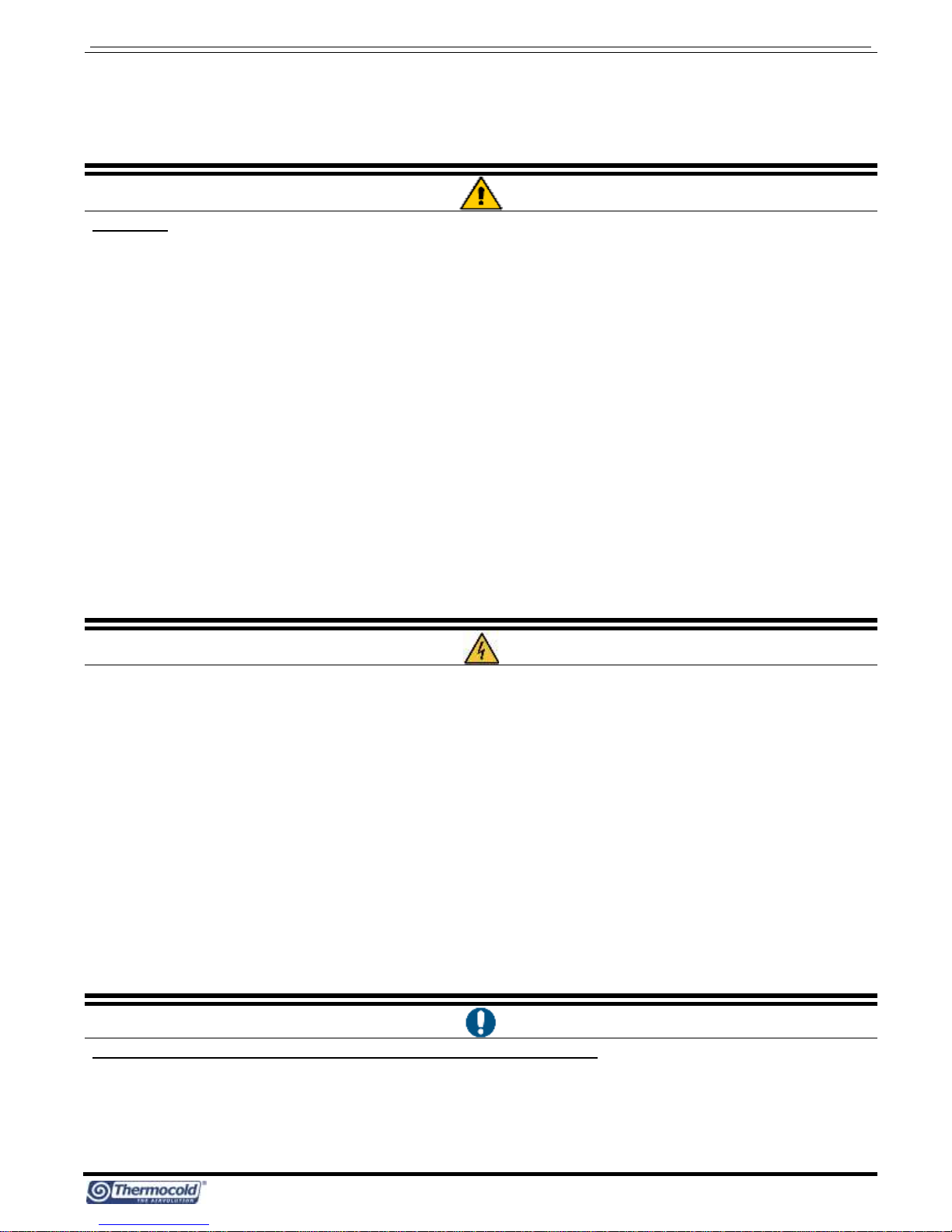
3.1 PERSONAL SAFETY EQUIPMENTS
During the operating and maintaining works, use the following personal protective equipment.
Protective clothing: Maintenance men and operators have to wear protective clothing that complies with the basic
safety requirements currently in force. In case of slippery floors, users have to wear safety shoes with non-slip soles.
Gloves: During maintenance or cleaning operation protection gloves have to be used
Mask and goggles: Respiratory protection (mask) and eye protection (goggles) should be used during
cleaning and maintenance operations.
3.2 WORKERS’ HEALTH AND SAFETY
The European Community has adopted a number of directives on workplace’s health and safety, which include 89/391/CEE,
89/686/CEE, 2009/104/CE, 86/188/CEE and 77/576/CEE directives. Every employer shall implement such provisions and ensure
that their workers to respect them.
It’s forbidden:
To remove and/or tamper with any safety device.
The access to the electrical board by unauthorized persons
To carry out any work on the equipment under voltage
To touch the equipment if you are not allowed.
The use of the appliance by children or unassisted disabled persons.
To touch the appliance when barefoot or parts of the body are wet or damp
To clean the unit when the power is ‘ON’.
To pull, remove or twist the electrical cables coming out from the unit.
Controller for MEX VS Chillers and inverter air / water heat pumps with axial fans
4
To step with your feet on the appliance, sit down and/or place any type of object.
To spray or pour water directly on the unit.
To dispose of, abandon or leave within reach of children packaging materials (cardboard, staples, plastic bag s, etc.) as they
may represent an environmental and health hazards.
To tamper with or replace parts of the equipment without the specific consent of the manufacturer. The manufacturer shall
have no whatsoever civilian or penal responsibility in case of unauthorized operations.
WARNING:
Before proceeding, you should read the user’s-installer manual accompanying appliance.
All the operations described below must be carried out only by QUALIFIED PERSONNEL.
The wiring to the terminal block must be performed by qualified personnel.
Any routine and/or not-routine maintenance operation shall be carried out when the equipment has been shut down,
disconnected from electric power supply.
Do not put neither your hands nor insert screwdrivers, spanners or other tools into moving parts of the equipment
The equipment’s supervisor and the service man have to receive suitable training for performing their tasks in safety.
The access to the electric panel is limited to authorized personnel only.
Operators have to know how to use personal protective devices and have to know the accident-prevention guidelines
contained in national and international laws and norms.
The operator’s workplace has to be kept clean, tidy and free from objects that may prev ent free movements. Appropriate
lighting of the work place shall be provided so as to allow the operator to carry out the required operations safely. Poor or too
strong lighting can cause risks.
Ensure that the work places are always adequately ventilated and that aspirators are working, in good condition and in
compliance with the requirements of the laws in force.
Not all the configurations can be simultaneously enabled and/or changed.
Other values different than those of default can ensure the proper operation of the unit, in case of doubt about the value to be
set contact please our office.
The company excludes any contractual and extra contractual liabilities for damages caused to persons, animals or objects, by
incorrect installation, setting and maintenance, improper use of the equipment, and the partial or superficial reading of the
information contained in this guide.
The supply voltage’s fluctuations cannot exceed ±10% of the nominal value. If this tolerance should not be respected, please
contact our technical department.
The power supply should respect the listed limits: failing this, warranty will not be valid immediately. Before any operation on
the unit, be sure that the power supply is disconnected.
Phase, neutral and ground connections should be respected.
The power supply cables must be sized correctly. We recommend a minimum cross section of 4mm
2
and a maximum length of
10m.
Install upstream of each unit an adequate protection and disconnection device of the electric power with delayed
characteristic curve, with at least 3 mm contact opening and with an adequate capacity of breaking and differential protectio n.
The capacity of the magneto-thermic circuit breaker must conform to the electric consumption of the unit; see TECHNICAL DATA
reported in the user’s-installer’s manual accompanying the unit. (Consideration should be taken of any eventual auxiliary
electric heater).
A good grounding is required; the manufacturer is not responsible for damage caused in case of lack of good grounding.
In case of maintenance, the unit must be disconnected from the power supply, the power cable plug must be easy for pulling it
out from the power socket by the operator for having possibility to check the unit from anywhere, the plug should remain
disconnected.
Use cables that meet the regulations in force in different countries.
Be sure, after about 10 minutes of operation the screws on the power supply terminal block that are well fixed.
Requirements before performing electrical work on the control panel:
Turn off the unit from the control panel ("OFF" displayed).
Put the switch “QF” general differential on OFF position
wait for 15 seconds before getting access to the electric board
Check the ground connection before beginning any operation.
Be sure that you are well insulated from the ground, with dry hands and feet, or by using insulating platforms and gloves.
Check that there is no foreign material near the system.
Controller for MEX VS Chillers and inverter air / water heat pumps with axial fans
5
4 PURPOSES AND CONTENTS OF THE MANUAL
This manual provides basic information for the installation, operation and maintenance of MEX VS units.
It is addressed to machine operators and it enables them to use the equipment efficiently, even if they do not have any previ ous
specific knowledge of it.
Not all the described functions can be individually and/or simultaneously selected. Please contact the technical office for any
information.
The manual describes the characteristics of the equipment at the time in which it is being put on the market; therefore, it may n ot
include technological improvements introduced later by the company as part of its constant endeavour to enhance the
performance, ergonomics, safety and functionality of its products.
The company introduces also technological improvements and is not constrained to update the manuals for previous versions of
appliances that could not be compatible. So make sure to use manual supplied with the installed appliance.
It’s recommended that, the user must follow the instructions contained in this booklet, especially those concerning the safet y and
routine maintenance.
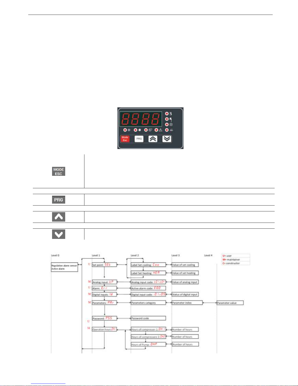
5 USER’S INTERFACE - CONTROLER
It is used to select the operating mode, and to reset the manual resetting alarms. The operating
mode changes as per the sequence below each time you press the Mode button:
off cool heat off
If the Domestic Hot Water (DHW) mode is enabled, the sequence is as follows:
off cool cool+san heat heat+sanoff
During the parameters’ setting, this button can be used to revert BACK to the previous level.
It allows you to enter into the setting menu parameters and to select the cool/summer,
heat/winter and DHW set point value.
UP button: In the setting mode, this button allows you to move up to a higher menu or to increase
the value of a parameter when you are in the “edit” mode.
DOWN button: In the setting mode, this button allows you to shift to a lower menu or to decrease
the value of a parameter when you are in the “edit” mode.
5.1 MENU STRUCTURE DIAGRAM
Level 0 (U) = always appearing
Level 1 (M) = it appears if you enter the maintainer (H80) or manufacturer password.
Controller for MEX VS Chillers and inverter air / water heat pumps with axial fans
6
Level 2 (C) = it appears if you enter the manufacturer password.
Level 3 (A) = it appears only via Modbus.
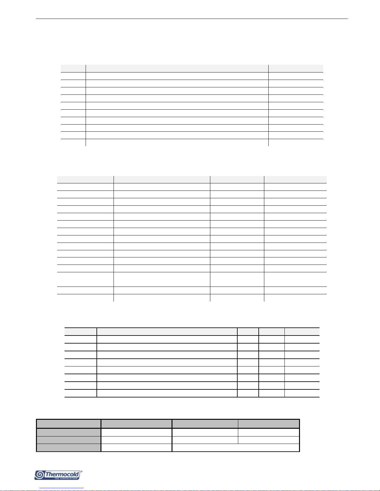
5.2 ANALOG INPUT MENU
By entering the maintainer password in the menu of analog inputs "tP", at the level 1 of the menu structure diagram of the unit
control board, you can read the values of the current probes:
tp
DESCRIPTION
Measurement unit
t01
Inlet water temperature
(°C)
t02
Outlet water temperature
(°C)
t03
Compressor inlet temperature
(°C)
t04
Compressor outlet temperature
(°C)
t05
High pressure
(bar)
t06
Low pressure
(bar)
t07
Outdoor air temperature
(°C)
t08
Plant remote temperature senor (if enabled)
(°C)
t09
Domestic hot water temperature (if DHW is enabled)
(°C)
t10÷t27
Parameters presents if installed the optional KIE module
-
5.3 PARAMETERS CATEGORIES
The parameters are classified into groups, each group is identified by a 3-digit code, while the index of each parameter is preceded
by one letter.
DESCRIPTION
GROUP IDENTIFICATION CODE
PARAMETER INDEX
VISIBILITY
Configuration
CnF
H-
USER / INSTALLER
Compressor
CP
C-
INSTALLER
Fan
FAn
F-
INSTALLER
Alarms
ALL
A-
INSTALLER
Regulation
Re
b-
INSTALLER
Pump
PUP
P-
INSTALLER
Electric heater
Fro
r-
INSTALLER
Defrost
dFr
d-
INSTALLER
Electronic valve
EEu
U-
INSTALLER
Offset
OFF
o-
INSTALLER
Mixer valve
rAd
i-
INSTALLER
**Solar
SUn
S-
INSTALLER
Inverter
compressors
nCP
n-
INSTALLER
Hz massimi
LbH
L-
UTENTE/INSTALLATORE
* DHW preparer
AcS
Ac-
USER / INSTALLER
(*) Programmable parameters if the optional KIE module is present
5.4 SETPOINT ADJUSTABLE BY THE USER
SETPOINT
DESCRIZIONE
UNITA’
DEFAULT
RANGE
Coo
setpoint in Estate
°C
7.0
5÷18
Hea
setpoint in Inverno
°C
45.0
35÷57
*San
DHW mode setpoint
°C
48.0
25÷57
Co2
Secondo setpoint in Estate
°C
18.0
Coo÷23
He2
Secondo setpoint in Inverno
°C
35.0
25÷Hea
**rCO
Mixer valve setpoint in Summer mode
°C
15.0
-50.0÷80.0
**rHE
Mixer valve setpoint in Winter mode
°C
30.0
-50.0÷80.0
**ACS
DHW instantaneous production setpoint
°C
45.0
0.0÷80.0
(*)
Adjustable Setpoint if the DHW mode is active
(**)
Adjustable Setpoint if is intalled the optional KIE module
Setpoint type
Setpoint (summer/winter)
Summer default (range)
Winter default (range)
First setpoint (°C)
Coo/Hea
7 (5÷18)
45 (35÷55)
Second setpoint (°C)
Co2/He2
18 (7÷23)
35 (25÷45)
Sanitary Setpoint (°C)
San
48 (25÷55)
The functionality of the second setpoint can be used only when you purchase the proper optional kit.

Controller for MEX VS Chillers and inverter air / water heat pumps with axial fans
7
5.5 DISPLAY
In Normal view displays the outlet water temperature reported to tenths of degrees, or the alarm code if at least an alarm is
active. In case of multiple alarms activation, it will display the first alarm, while the second appears when the first is reset. Into the
menu mode, the display depends on the current position where you are.
5.6 LED
Compressor LED
ON if the compressor is running
OFF if the compressor is off
FLASHING if timings are in progress waiting for compressor’s start up
Sanitary water LED
ON if sanitary mode is active
OFF if the sanitary mode is not active
FLASHING if sanitary production in progress (sanitary valve is active)
Defrosting LED
ON in defrost operating mode
OFF if defrosting mode is disabled or completed
FLASHING if defrosting cycle interval’s time is in progress.
Antifreeze electric heater LED
The LED is ON if the antifreeze electric heater is active.
Water pump LED
The LED is ON if the water pump is running.
Alarm LED
The LED is ON if an alarm is activated.
Heat LED
The LED is ON if the unit is in the heating mode operation.
Cool LED
LED is ON if the unit is in the cooling mode operation.
5.7 INPUT/OUTPUT (I/O) PORTS
The I/O (inputs and outputs) that can be set to enable the control functions are listed below.
In order to set the I/O please enter with service password to the parameters PRGPSSPRG (insert the service password)
PRG Par PRG CnF.
Ports
Parameter
Terminals
Factory Setting
Description
Value
Function
ST8
H19
SE/SE 0 Not set
Programmable analog input with NTC sensor
10kΏ at 25°C β 3435
ST9
H20
SAN/SAN 0 Not set
Programmable analog input with NTC sensor
10kΏ at 25°C β 3435
ID2
H39
ONOFF/ONOFF
2
Remote on/off
(See paragraph 10.5.1)
Voltage free contact digital input
ID3
H40
SW/SW
3
Remote summer/winter
commutation
(See paragraph 10.5.2)
Voltage free contact digital input
To activate this function see paragraph 10.5.2
ID7
H44
SE/SE 0 Not set
Voltage free contact digital input, programmable
instead of the analog input ST8 (H19=0)
ID8
H45
SAN/SAN 0 Not set
Voltage free contact digital input, programmable
instead of the analog input ST9 (H20=0)
DO3
H58
AEH (phase)
AEHN (neutral)
22
Command of the plant
auxiliary E-heater
(See paragraph 10.7.1)
Under voltage output single phase 230Vac, 50Hz,
5A resistive, 1A inductive.
To activate this function see paragraph 10.7.1
DO4
*H59
DO4 (phase)
DO4N (neutral)
0
Not set
Under voltage output single phase 230Vac, 50Hz,
5A resistive, 1A inductive.
DO5
*H60
DO5 (phase)
DO5N (neutral)
0
Not set
Under voltage output 230V ac, 50Hz, 5A
resistive, 1A inductive.
OC1
H61
NO1 (phase)
N1 (neutral)
NC1 (phase)
Command of DHW valve
(See paragraph 10.3)
Switching contact, single phase voltage 230Vac,
50Hz, 5A resistive, 1A inductive.
NO1= Normally open
NC1= Normally-Closed
To activate this function see paragraph 10.3
OC2
H62
NO2 (phase)
N2 (neutral)
NC2 (phase)
Command of Double
setpoint valve
(See paragraph 10.17)
Switching contact, single phase voltage 230 ac,
50Hz, 5A resistive, 1 A inductive.
NO2= Normally open
NC2= Normally-Closed
To activate this function see paragraph 10.17
(*) Do not change if the KA kit is installed is present
Controller for MEX VS Chillers and inverter air / water heat pumps with axial fans
8
Note: Note that with the adoption of the optional “KIE” module helps to increase the input/output (I/O) ports. For more
information, please refer to the related manual of this module.
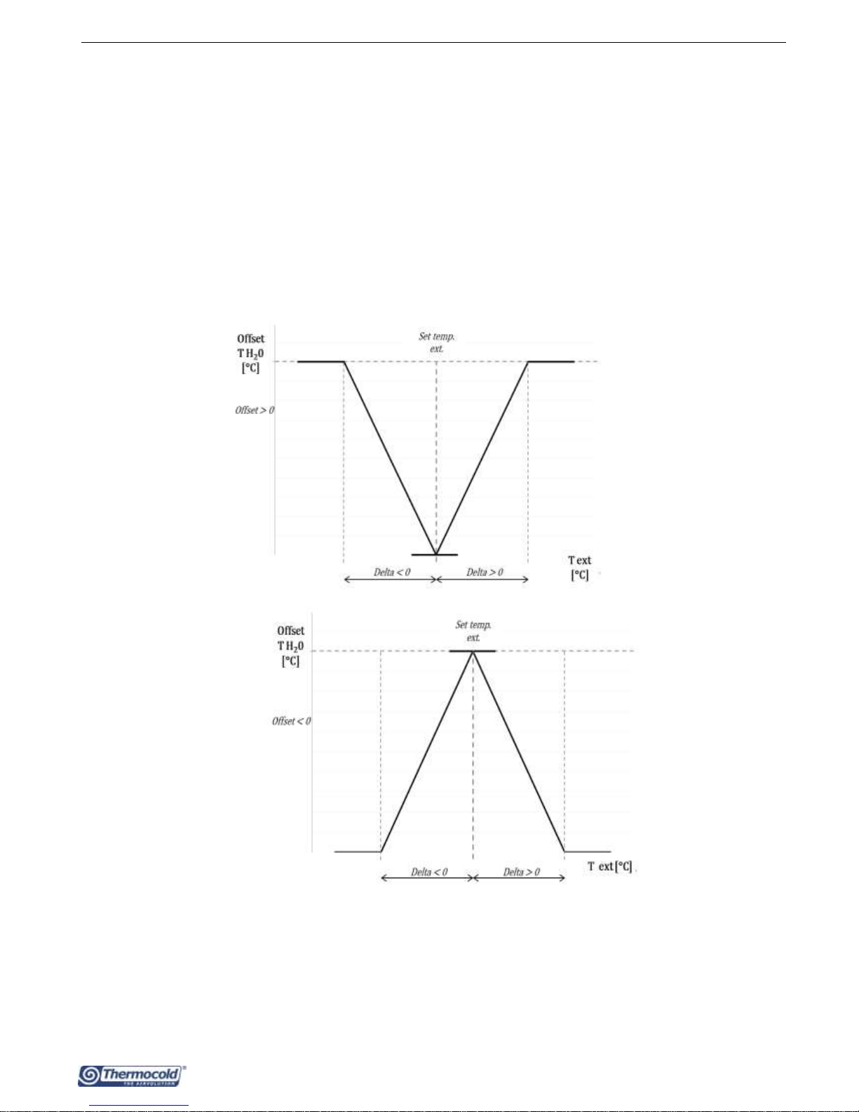
6 DYNAMIC SET-POINT ADJUSTMENT
The controller can change the set-point by adding a value depending on the outdoor air temperature sensor. In this case, you need
to change the values of the parameters from b08 to b14 following the indications below (the settings should be done by the
installer):
Parameters of the controller PAr->rE->
• b08 = dynamic set-point, enabled = 1/ unabled = 0.
• b09 = offset max in cooling mode operation.
• b10 = offset max in heating mode operation.
• b11 = Outdoor temperature setting in cooling mode.
• b12 = Outdoor temperature setting in heating mode.
• b13 = Temperature difference in cooling mode operation.
• b14 = Temperature difference in heating mode operation.
Curve of the set-point variation as a function of the outside temperature:
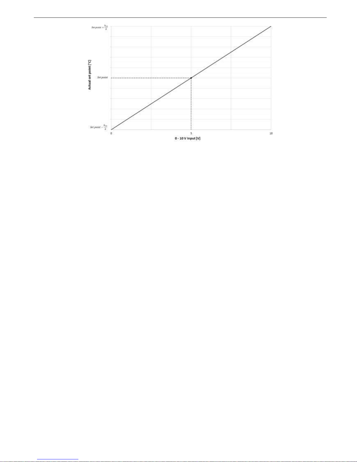
7 SET-POINT ADJUSTMENT FROM 0-10V INPUT
Another type of setting that allows to change the set-point by adding (or subtracting) a value in function of the 0-10V analogue
input (if enabled). To enable the function, you must set the H21 parameter to be 40, and change the values of the parameter
b15 (range 0-10), taking into account that if b20=0 input of 0-10V, if b20=1 ratiometric input type:
- b20=0 if this input is at 0 volts you will have the actual set point: set point (Coo/Hea) - b15/2.
- b20=0 if the input is at 5 volts the set point will be the set of (Coo/Hea) mode.
- b20=0 if the input is 10 volts you will have the actual set point: set point (Coo/Hea) + b15/2.
Cooling
Heating
Controller for MEX VS Chillers and inverter air / water heat pumps with axial fans
9
- - b20=0 when the input is at 0%, the actual set point is: set point (Coo/Hea) - b15/2.
- - b20=0 when the input is at 50%, the set point will be the set of (Coo/Hea) mode.
- - b20=0 if the input is 100%, the actual set point is: set point (Coo/Hea) + b15/2.
The signal must be applied to the terminals 0-10V+ and 0-10V- (see the wiring diagrams).
Note: In "cooling" mode, considering that the set-point by default is set to be 7°C, the parameter (b15) should not assume any
value greater than or equal to 6 in order to prevent that the new set-point set from 0-10V input to take values below the threshold
of the antifreeze operation which is 4°C.
8 CIRCULATOR
The circulating pump can be set according respecting the following operating modes:
- Thermoregulatory operation (default)
- Thermoregulatory operation with periodic activation
- Continuous operation
The circulator will switch off immediately if:
Presence of blocking pump alarm including the manual reset alarm of the flow switch;
The unit is off or in stand-by mode or when it’s switched off from remote input, the circulating pump (if is ON) will always
turn off after P02 (tenths of a minute):
The circulator is always running if the antifreeze heaters are activated.
The circulator can be configured with the parameter P03 in order to operate independently than the compressor or under call.
0=Continues operation
1=Operation under thermoregulatory call
Note: If the automatic reset alarm of the flow switch is active, the pump is anyway in operation even if the compressor is off.
Contrarily, the circulator remains always in operation if the antifreeze heaters are on or when the hydraulic pump operates i n
antifreeze mode. The operation in antifreeze mode will start if the water setting temperature decreases below P04 °C (default
value 5°C), and it will be disabled if the water setting temperature increases above P04+P05 °C (the default value of P05 is 2,0°C).
The adjustment of the circulator is linear (see Paragraph 8.5).
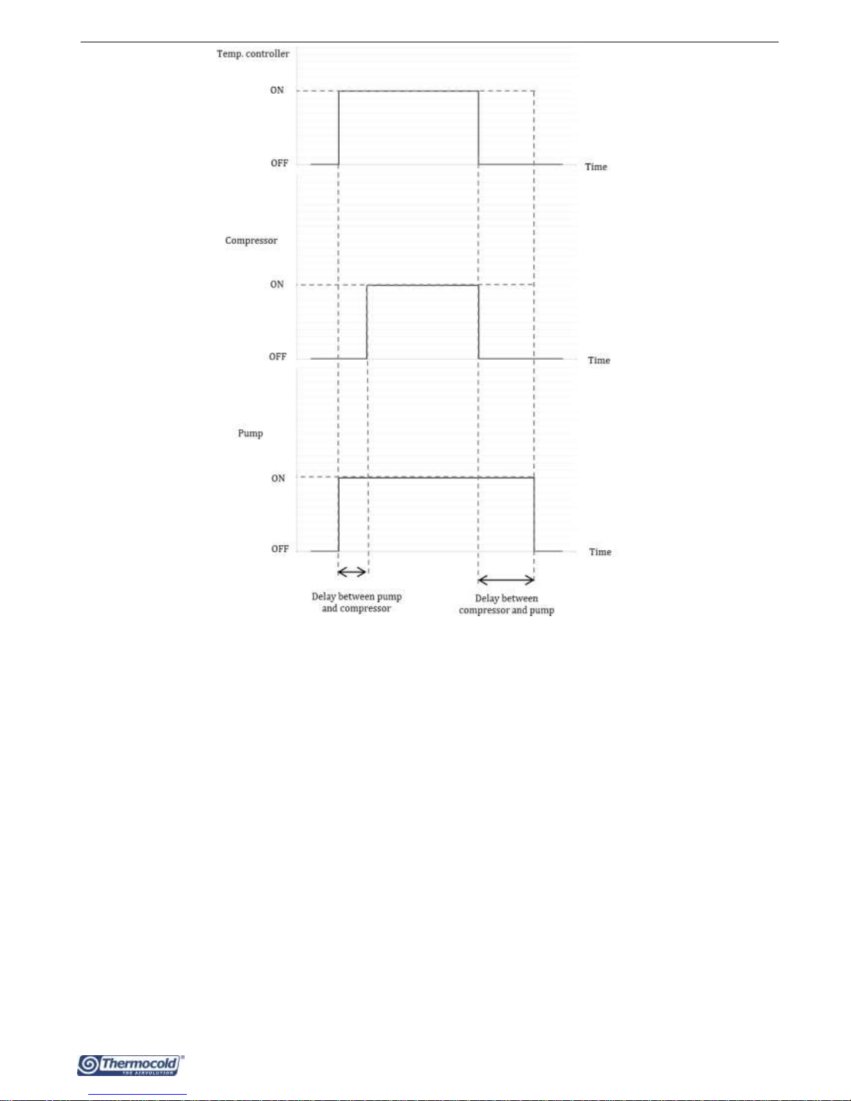
8.1 OPERATION BY MEAN OF THERMOREGULATOR (Default)
During this operating mode (P03=1, default), the thermoregulator actuates the pump; after a time delay of P01 seconds from
startup of the pump, the compressor also will turn on. However, during the power off status, the pump turns off with a delay time
of P02 minutes after turning off status with thermoregulator call (the turning off status is corresponding to the off status of the
compressor).
In the case of activation of the flow switch alarms with automatic reset, the pump remains still in operation even if the compressor
is stopped.
If you enable the operation of the unit from the remote "on-off" digital input (see Paragraph 10.5.1) the circulating pump will be
activated immediately for a duration of 2 minutes regardless of the on-board controller thermoregulation of the unit (the
activation of water recirculation in the plant leads to a correct activation of the thermoregulation).
Controller for MEX VS Chillers and inverter air / water heat pumps with axial fans
10
8.2 OPERATION BY THERMOREGULATOR WITH PERIODIC ACTIVATION
The function is disabled if P17= 0 (default). If the pump is set to operate by thermoregulation call (P03 = 1, default), it will be
activated periodically for a time period defined by the parameter P17 (in seconds) after a counting time set by the parameter P16
(in minutes), activated when the pump is turned off for satisfied thermoregulation.
In the case of the activation of the flow switch alarm with automatic reset the pump is still operating even if the compressor is off.
The periodic function is also interrupted in the case of the intervention of the antifreeze thermo-regulator constraining the
operation of the pump.
8.3 OPERATION WITH ACTIVE ELECTRIC HEATER
See paragraph 10.9.
8.4 CONTINUOUS OPERATION
In this operating mode (enabled if P03=0), the pump is always running. It turns off only when the unit is in OFF status. The pump is
always ON even if automatic reset flow switch alarm is ON and even the compressor is off.
8.5 PROPORTIONAL ADJUSTMENT OF THE PUMP
The pump speed can change as a function of the temperature difference between the water inlet and the water outlet of the heat
exchanger, according to the diagram shown below, where:
P07: maximum speed of the modulating pump (%)
P08: minimum speed of the modulating pump (%)
P09: set Delta T inlet/outlet water of the modulating pump (°C)
P10: Delta modulating pump (°C)
 Loading...