

Thermocet Trimline 73, Trimline 73H Operating And Installation Instructions

Page.1
GREAT BRITTAN-GB
IRELAND-IE
OPERATING AND INSTALLATION INSTRUCTIONS
1033 / 1034
Trimline 73
(1033)
Trimline 73H (1034)

Page.2
OPERATING AND INSTALLATION INSTRUCTIONS
TABLE OF CONTENTS
1 . General Page 3
1.1 Contents of the package
2. Safety device Page 4
2.1 Safety
3. Remote control Page 5
3.1 General
3.2 Manual transmitter
3.3 Screen setup
3.4 Time setup
3.5 Setting the desired temperature
3.6 Setting the Timer
3.7 Changing the signal codes
3.8 Controls (remote control)
3.9 Possible error messages
3.10 Setting the flame size / Extinguishing the fire
3.11 Switching the unit off
3.12 Inserting and replacing the batteries
4. Manual control Page 8
4.1 Igniting the fire
4.2 Extinguishing the fire
4.3 Switching the unit off
5. Initial start-up Page 9
5.1 Daily maintenance
5.2 Important tips
6. Installation instructions Page 10
6.1 General instructions
7. Concentric flue system Page 11
7.1 Components of the concentric flue system
7.2 Construction of concentric flue system
7.3 Installation instructions regarding existing flues
7.4 Parts
7.5 Installation
7.6 Cleaning and maintenance
8. Instructions for the Mertik Maxitrol GV60 and the Remote Control: Page 15
9. Maintenance check-up list Page 18
10. Maintenance activities Page 19
11. Installing the unit Page 20
11.1 Unit components
11.2 Connection to the gas pipes
11.3 Preparation and installation of the unit
11.4 Fitting the ceramic log inset
11.5 Fitting the optional pebble set
11.6 Fitting the optional panels
11.7 Fitting the optional slats
11.8 Mounting instruction Iron Front
12. Technical Details GV60 Page 22
12.1 Gas-technical specifications
13. Problems and possible solutions Page 24
Illustrations Page 25–35
ALL RIGHTS RESERVED.
(1/21072008)

Page.3
We hope you really enjoy the warmth of your new gas fire. Read these instructions carefully before installing and using the gas fire. Keep these instructions in a safe place. Always provide the following information if the gas fire breaks down: model and serial number, which can be found on the unit. Your purchase invoice is your proof of warranty.
1. General
The entire unit is delivered to you with your choice of mantle and/or accessories. See the installation instructions
for the relevant mantle and/or accessories that are packaged separately from the unit. Check the unit immediately
after delivery to confirm that it has not been damaged during transport. If it is damaged in any way, please inform your supplier immediately and provide as many details as possible.
Attention
The unit must be installed, connected and checked by a qualified fitter based on national, regional, and local
standards and regulations. The fitter must inspect the unit for tightness in relation to gas and combustion products and correct operation of the different components and functions.
The flue tube system and the outlets in the outer wall or roof face must also meet the requirements of the applicable regulations.
The unit falls in the closed unit category, in a set-up location without a fan and with a chimney loss that is
greater than 17% (non-condensing).
Warning
Gas fires become hot when in use. Therefore care should be taken, for example, by keeping children and those
requiring help away from the immediate vicinity of burning fires. Gas fires must not be placed on or against
flammable materials (curtains, etc.).
Contents of the packaging
1 x Fully assembled unit:
Trimline 73 (1033)”NG” or “LPG” or 1 x Trimline 73H (1034 incl. Slats back and side).
1 x Convection set
1 x Remote control
2 x Restriction plate
1 x 9V battery
4 x 1.5V AA batteries
1 x Operating and installation instructions
1 x Wood imitation set ”NG” or “LPG”
1 x Suction cap
Additional
Luxury Big stone panels or Tile panels (only 1033)
Slat set back and side (only 1033)
Pebble set
Iron Front (only 1033)
Fireplace Castello (only 1033)
Mantle iron

Page.4
2. SAFETY DEVICE
The unit is fully safeguarded by means of thermo-electric pilot light protection to prevent unforeseen discharge
of gas from the main burner.
2.1 Safety
Do not place ceramic burner decoration material or logs against the pilot burner. Ensure the pilot light is able to
burn freely over the main burner. Good ignition of the main burner is only guaranteed if this is the case. Not adhering to these instructions can lead to dangerous situations.
The unit, complete concentric flue system and flue terminal need to be cleaned and checked annually by a
recognised gas technician/fitter, so the unit continues to operate safely. For additional instructions, see
Chapter 10: Maintenance.
If, for whatever reason, the pilot light extinguishes, you must wait 5 minutes before igniting the pilot light
again.
The unit may not be operated without the glass panel being in place.
It is not permitted to place flammable materials on the ceramic wood inset.
The layout of the main burner with ceramic burner decoration material and wood inset may under no circumstances be changed or added to.
Light flammable materials, such as nylon clothing or flammable liquids, may not be placed near the unit.
Ensure children and other persons unaware of the operation of a gas unit, are supervised at all times when
near the unit.
Use a fireguard to protect against burns and protection of the children and persons named above.
Page.5
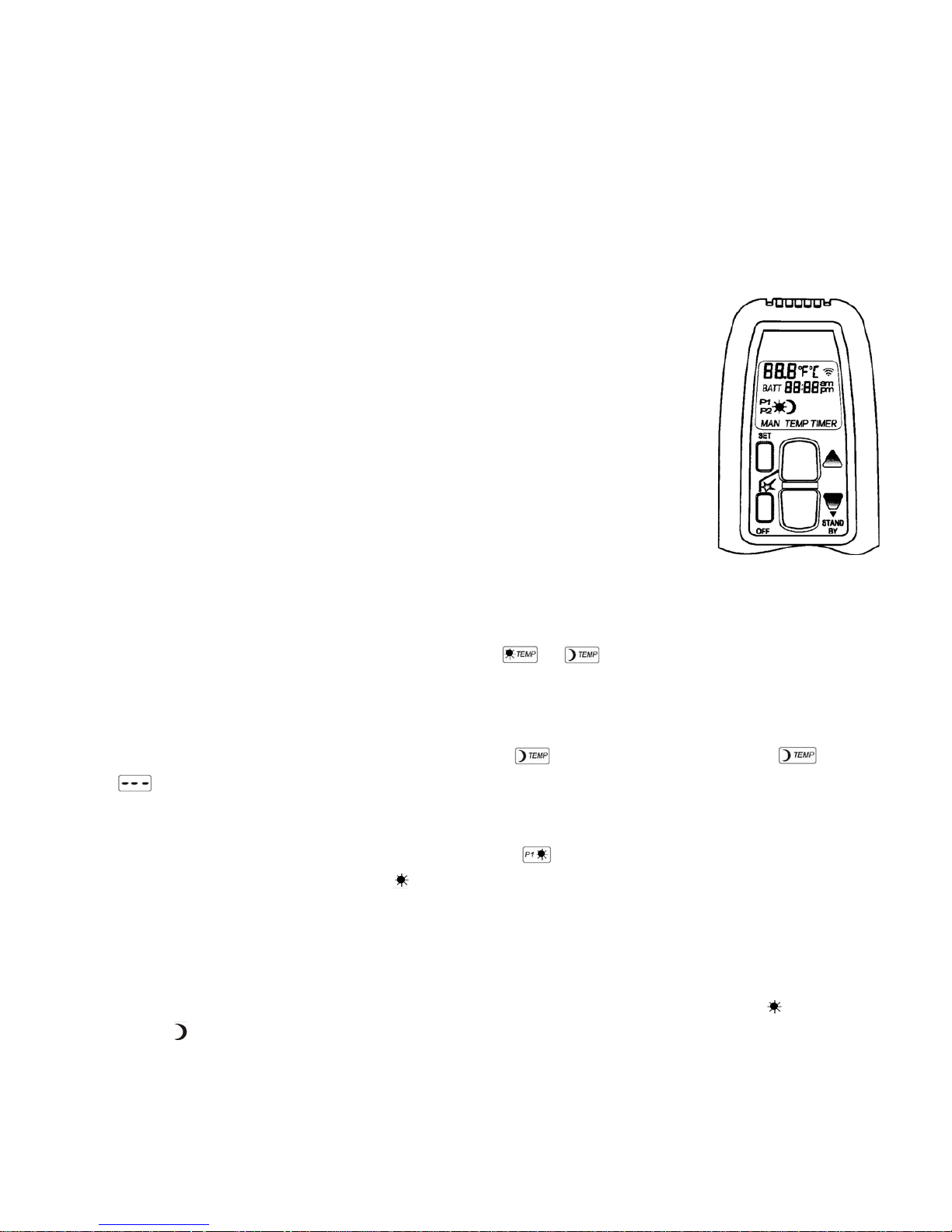
3. REMOTE CONTROL
3.1 General
* The unit is operated using a radio-controlled remote control. This consists of a manual transmitter and a re-
ceiver. The receiver is connected to the gas control block.
* The receiver and gas control block are located in the control cabinet.
3.2 Manual transmitter
* The transmitter uses a radio-controlled signal. The signal code is set at the factory, but can be adjusted if
required. (See 3.7)
3.3 Screen setup
* After fitting the batteries, simultaneous pressing of OFF and ź allows you to
change from °F (and 12-hour clock) to °C (and 24-hour clock), or vice versa.
* Wait a moment or press OFF to return to MAN mode.
3.4 Time setup
* For SET mode or program mode, simultaneously press ź and Ÿ.
* The time can be set while the screen is flashing.
* Press Ÿ to input the hour and ź to input the minutes.
* Wait a moment or press OFF to return to MAN mode.
3.5 Setting the desired temperature
* Press the SET key briefly to select the required mode
or
* Keep the SET key pressed in until the screen starts flashing.
* Subsequently press ź or Ÿ to set the required temperature.
* Wait a moment or briefly press the OFF key to select the MAN mode.
* If the temperature setting needs to be switched off with (low battery usage), then lower until
appears on the screen.
3.6 Setting the timer: P1 and P2
* Press briefly on the SET key to select the required mode
* Keep the SET key pressed in until P1
(heating period 1) flashes on the screen.
* Set the commencement time of the first (1
st
) heating period by pressing on Ÿ to input the hour, and on ź
to input the minutes.
* Briefly press the SET key; P1 now appears on the screen. Set the time the first (1
st
) heating period needs to
end.
* Press the SET key again to set the beginning and end of the second (2
nd
) heating period P2 (ON)
and P2
(OFF).
* Wait a moment or press OFF to return to MAN mode.
Remote Handset
Page.6
3.7 Changing the signal code
It is possible that there are multiple units within the reach of one transmitter; the transmitter can be customised for each unit if required. This can be performed by changing the signal code in the transmitter.
* There are 15 other codes that can be set by adjusting the position of one or more
“DIP switches” in the transmitter.
* The “DIP switches” are accessible after opening the battery holder of the trans mitter.
* Simultaneously press the reset key on the receiver and the ź key on the trans mitter (approximately 20 seconds).
* When the receiver has read the new code, the gas block responds and is ready for use.
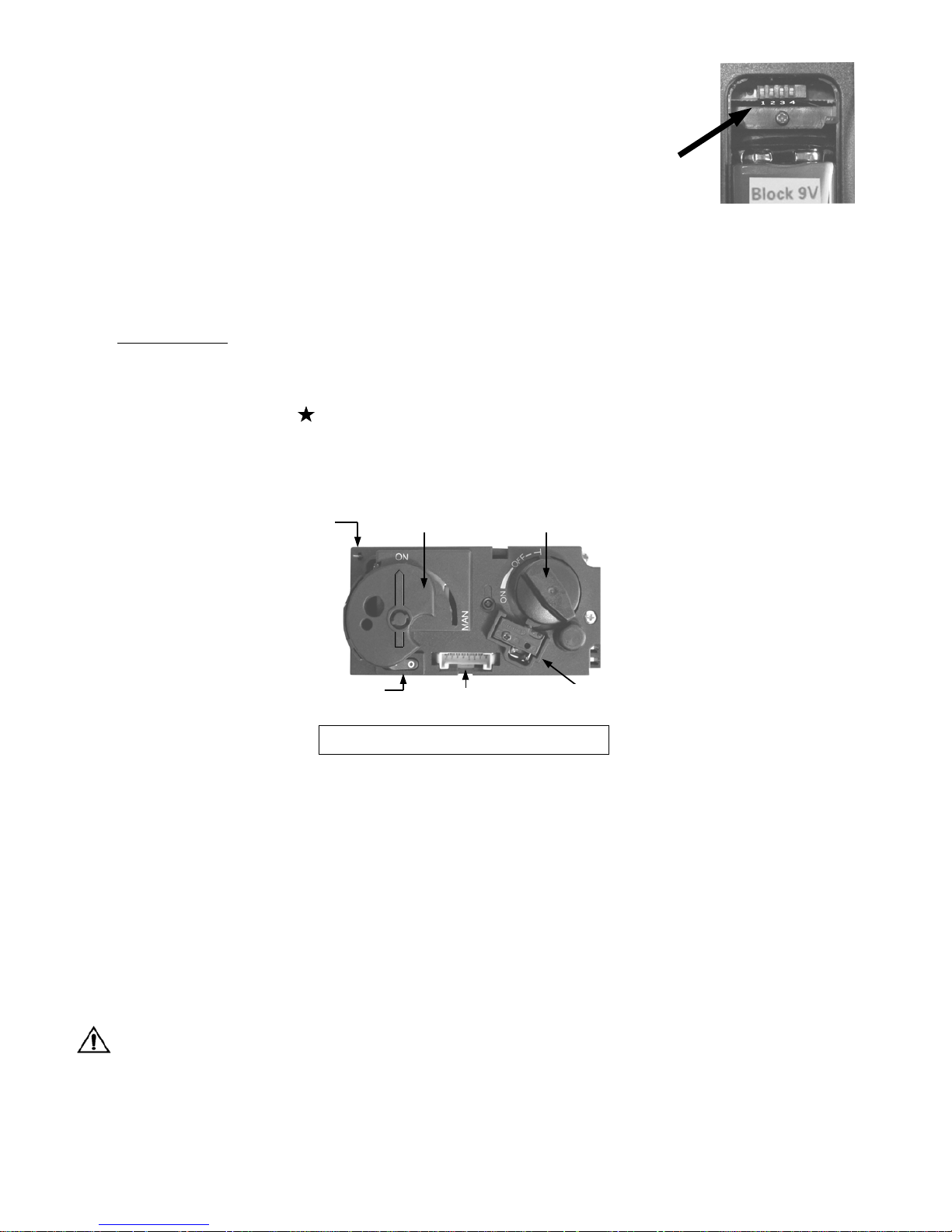
3.8 Controls (Remote Control)
Igniting the fire
* Open the gas valve that has been installed in the gas pipe to the unit.
* Press the “
O I” switch, on the gas control block, in the “I” position.
* Turn the operating button on the gas control block, into the
ON position.
* Simultaneously push the
OFF and Ÿ keys on the manual transmitter. A short sound signal will confirm
commencement. Short sound signals will then follow until the pilot flame and main burner are ignited.
After the main burner is ignited, the flame size will automatically move into the maximum setting.
3.9 Possible error messages
* Long sound signals during the ignition: Receiver batteries are almost empty. (After this signal occurs, the
unit can be switched on approximately another 10x).
* 5 seconds of continuous sound signal: Error message. For example: one of the cables is not connected, the
“
O I” switch is not in the “I” position.
* 5x short sound signal: Ignition of the pilot flame and main burner is unsuccessful.
Possible cause: air in the pilot pipes.
Important:
If the pilot light extinguishes, one should wait at least 5 minutes before repeating the aforementioned
steps.
“DIP-switches” in battery-
holder handset
Piëzo Ignitter
(Manual)
Manual knob
Main valve knob
Microswitch
“O I” Switch
8 Wire Receiver Jack
Combination Control, Cover

Page.7
3.10 Setting the flame size / Extinguishing the fire
* After the burner is ignited, the flame size will automatically move into the maximum setting.
* Press ź to reduce the flame size and turn off the burner.
(Extinguishing the fire: “
STAND BY”). (Pressing the key for a short time gradually reduces the flame.)
* Press Ÿ to increase the flame. (Pressing the key for a short time gradually increases the flame.)
3.11 Switching the unit off.
* Press ź to reduce the flame size and turn the burner off (“STAND BY”).
* Then press the OFF key to turn the entire unit off, including the pilot flame.
* If the unit is not used for an extended period of time, you can turn the “
O I” switch, on the gas control
block, into the “
O” position, in order to save battery life.
* In this case, it is also recommended you close the gas shut-off cock in the supply line.
Important: If, for whatever reason, the pilot light extinguishes, you must wait 5 minutes before igniting
the pilot light again.
Malfunction
If the signals from the manual transmitter are not received adequately by the receiver, this may be caused by:
* Flat batteries: replace the batteries.
* An electronic problem: can be solved by pressing the “
RESET” key on the receiver.
* Contact your fitter if the unit regularly turns off.
3.12 Replacing the batteries
* The batteries of the manual transmitter and receiver have a life span of approximately one year. The use of
alkaline batteries is recommended.
* The batteries need to be replaced when the following occur:
1. Manual transmitter: BATT appears on the display.
2. Receiver: long sound signals can be heard during the ignition.
1. Manual transmitter:
* Open the small lid on the back.
* Carefully remove the 9V block battery and loosen the battery from the contact holder. Do not pull the
wires!
* Connect the new battery and place it back into the transmitter. Close the lid.
2. Receiver:
* Carefully remove the entire receiver from the holder.
* Slide the small lid open.
* Remove the batteries from the battery holder.
* Place 4 new 1.5V batteries (type LR6 or AA) in the battery holder in the indicated manner. The spring al
ways needs to be against the minus (-) pole of the battery.
* Close the lid and place the receiver back into the holder.
Incorrect placing of the batteries can irreparably damage the electronics or power.
Only replace the batteries when the unit is completely turned off.
Remove batteries only with nonmetal tool.
Removing batteries with a metal object can damage electronic control permanent.
Page.8
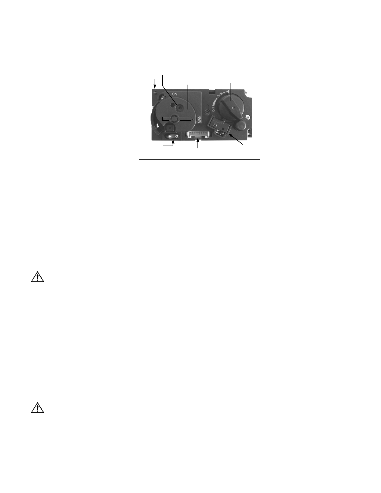
4.0 MANUAL CONTROL
The unit may be operated by hand if there is a defect in the remote control. To do so, the ignite (piezo)cable of
the receiver must first be removed and carefully slid into the piezo connector on the gas control block.
Igniting the fire
* Open the gas shut-off cock that has been installed in the gas pipe to the unit.
* Press the “
O I” switch, on the gas control block, in the “I” position.
* Turn the motor button, on the gas control block, completely to the right. The button will make a "click”
sound.
* Turn the operating button on the gas control block, into the “
MAN” position. A metal circle in the operat-
ing button will become visible.
* Push the metal circle inwards. For example, with a pen. Gas will now flow to the pilot flame.
* While keeping the metal circle pressed down, press the (square) piezo button (along the “
O I” switch) sev-
eral times to ignite the pilot flame. You will be able to see whether the pilot flame is burning through the
glass window.
* If the pilot flame is alight, keep the metal circle pressed down for another 10 seconds and then let go.
Important: If the pilot light extinguishes, one should wait at least 5 minutes before repeating the
aforementioned steps.
* Turn the operating button to the ON position. The burner may or may not ignite, depending on the position
of the motor button.
* By turning the motor button to the required setting to the left, the burner will ignite and the flame size can
be adjusted.
Extinguishing the fire
Turn the motor button, on the gas control block, completely to the right. The button will make a "click” sound.
The burner will turn off. The pilot flame continues to burn.
Switching the unit off
Press the "O I” switch, on the gas control block, in the “O” position. The pilot flame will extinguish.
If the fireplace is not used for an extended period of time, we recommend closing the gas shut-off cock in the
supply line.
Important: If, for whatever reason, the pilot light extinguishes, you must wait 5 minutes before igniting the pilot light again.
Piëzo Knop
Piëzo Ignitter
(Manual)
Manual knob
Main valve knob
Microswitch
“O I” Switch
8 Wire Receiver Jack
Small metal circle for
Manual ignition
(Combination Control, Cover Manual position

Page.9
5. INITIAL START-UP
The unit has a layer of heat-resistant varnish that resists very high temperatures. An unpleasant smell may develop in the first hours after starting the unit due to burning in of the varnish; however, this is not dangerous. To
accelerate this process, allow the unit to burn at the highest setting for several hours and ventilate the area well.
After the first time the unit is turned on, a light deposit may form on the inside of the window. This is due to the
varnish hardening. After the fireplace has cooled down, this deposit can be removed using a fireplace glass
cleaner or ceramic hotplate cleaner.
5.1 Daily maintenance
* Avoid having a lot of dust and cigarette smoke, candle and oil lamp particles in the air of your home.
Heat ing of these particles through the convection system of the unit, can lead to discolouring of walls and
ceilings. It is therefore advisable to ensure the area containing the unit is always sufficiently ventilated.
Regularly remove any dust that has settled behind the operating lid with a vacuum cleaner.
If the glass is broken or cracked, it should be replaced immediately by a recognised fitter before the
unit is used again.
* The unit must be switched off immediately if something is spilt on it. It should only be cleaned once the
unit has cooled down. Never use abrasive, aggressive cleaning products or fireplace cleaner; only use a dry
cloth that does not give off fluff.
* Your local specialised dealer will be able to provide you with spray cans containing heat-resistant varnish,
so that small stains or damages may be touched-up during annual maintenance.
5.2 Important tips for gas heating or wood fuelled units and fireplaces.
Prevent discolouration of walls and ceilings!
There are always particles in the air in each living area even if the area is vacuum cleaned regularly!
These particles are easily visible when the sun streams in. This issue will not arise if the amount of parti cles in the air is limited. If these particles are present in greater quantities and particularly if the air is con taminated by soot and tar particles, for example, through the burning of candles or oil lamps and cigarette
or cigar smoke, then we can speak of a poor inner climate! Cooled air slowly flows over the floor to the
heater in a heated living area. This air is heated in the convection system of the fireplace or heater, result ing in a quickly rising column of air that subsequently spreads through the room again. This means there is
always dust and other polluting particles depositing on cold and often damp surfaces. This issue occurs es pecially in a new building (building damp) that is not yet dry. An undesirable consequence of this phe nomenon could be discolouration of walls and or ceiling!
How can this problem be avoided?
* With a newly built fireplace or following renovation, wait at least 6 weeks before firing up.
* The building damp must have disappeared completely from the walls, floor and ceiling.
* The room where the unit is located must be well ventilated.
* The required air ventilation must be in line with local building regulations.
* Limit the use of candles and oil lamps and keep the taper as short as possible.
* These two creators of atmosphere ensure considerable quantities of polluting and unhealthy soot particles
in your house.
* Among other things, cigarettes and cigars contain tar that will precipitate on cold and damp walls during
heating.
* This may occur above radiators and light fittings and with ventilation grilles (if there is a poor internal
climate), although to a lesser degree.
Page.10
6. INSTALLATION INSTRUCTIONS
Important
The installation may only be performed by an authorised person
6.1 General instructions
* The gas fireplace must be installed, connected and inspected as a closed unit by a qualified fitter, according
to national, regional, and local standards and regulations.
* The flue tube system and the outlets in the outer wall or roof face must also meet the requirements outlined
in the applicable standards and regulations.
* The temperature of the walls and shelves near the side and back of the unit may not be more than 80°C
higher than the temperature of the environment.
* The unit has been approved in combination with the Metaloterm US system number: 0063-CPD-6308 con centric flue system Ø100 mm - Ø150 mm and Ø130 mm - Ø200 mm , in accordance with European CE
standards for gas units, and may therefore only be applied with this system.
* The unit needs to be inspected by the fitter for local gas distribution (gas type and gas pressure) as indicated
on the identification plate.
* The instructions are only applicable if the relevant country code is stated on the unit. If this is not the case,
the gas technical information for the relevant country needs to be consulted and modifications discussed
with the manufacturer.
* There will be air in the gas pipes when the unit is first used. The gas pipes therefore need to be vented first.
* Ignite the heater according to operating instructions and check whether the burner flame is uniform. After
the unit has been used for the first time, you should remove any deposits resulting from convection-curing
of the unit, from the glass window using a glass cleaner for heaters.
Warning:
Never install the unit against or within a flammable wall!
Distance to flammable materials:
* With respect to the front, side and top of the unit, a distance of 1000 mm needs to be kept between the unit
and: curtains, floor covering, upholstery and fabrics, and/or other flammable material unless stated other
wise in these instructions.
Distance to non-flammable materials:
* The unit needs to be placed a minimum distance of 50 mm from the wall unless stated otherwise in these
instructions.
Important
* Construction material for fireplaces and mantles etc., or for an assembly must be made of non flammable
material. This also applies to floors and ceilings. Never use flammable materials near the unit in compli ance with the abovementioned instructions.
Note: Please contact your supplier if you are unsure.
Page.11
7. Concentric flue system CC
The concentric flue system consists of a 100 mm Ø inner flue concentric with a 150 mm Ø outer flue. These flues
have been set up concentrically; the combustion gases are exhausted through the internal flue while the fresh
combustion air is supplied between the internal and external flues.
7.1 Components of the concentric flue system. (See page 28)
Different connections are possible using the concentric flue system. These are:
Through the roof face and through the exterior wall.
The layout used for this system can be laid in different ways but there are a few important conditions:
* The maximum allowable vertical flue length is 12 metres (the sum of the flue length and the calculation
lengths for the bends).
* 90° bends have a 2-metre horizontal calculation length.
* 45° bends have a 1-metre horizontal calculation length.
* The outlet can be installed at any point on the roof face or exterior wall (supply and discharge in an identi cal pressure area), but must meet applicable regulations.
x Duct pathways may not be insulated.
Important
* Ensure the restriction plate is mounted in the correct manner, as indicated in these instructions.
* The correct restriction plate will provide the unit with the most optimal efficiency, flame image and com bustion.
* Mounting an incorrectly placed restriction plate may cause malfunction of the unit.
CC FLUE SYSTEM ARTICLE NO.s
DESCRIPTION SIZE (mm) CODE NR. STAINLESS STEEL
Ø 100
A) CONCENTRIC PIPE 1000
500
250
401410100000
401410050000
401410025000
B) 45° BEND (2 PIECE SET, Ø 100 ONLY) 401420045002
C) WALL BRACKET 401430110000
D) 90° BEND 401420090000
E) ADJUSTABLE WALL BRACKET 401430120000
F) CONCENTRIC FITTED PIPE 250 401412025000
G) UNIVERSAL MOUNTING PLATE 401450150000
H) CLAMPING STRIPS 401430100000
I) CENTRING PLATES (SET) 401450130000
J) FLAT ALUMINIUM ROOFING SHEET 401472000000
K) STORM COLLAR 401470100000
L) EXTERIOR WALL DUCT 401450160000
M) LEAD ROOFING SHEET, SLOPING 20-45° 401476020000
N) ROOF PASS-THROUGH 401450180000
O) ROOFING SHEET, SLOPING 5-30° 401474005000
 Loading...