

Page 1

Page 1
OPERATING AND INSTALLATION INSTRUCTIONS
1080
Trimline 2050 OH
UNITED KINGDOM-UK IRELAND-IE
Page 2

Page 2
TABLE OF CONTENTS
1. General Page 3
1.1 Contents of the package
2. Safety of the unit Page 4
2.1 Safety
3. Remote control Page 5
3.1 General
3.2 Manual transmitter
3.3 Screen setup
3.4 Time setup
3.5 Setting the Timer
3.6 Controls (remote control)
3.7 Possible error messages
3.8 Setting the flame size / Extinguishing the fire
3.9 Switching the unit off
3.10 Inserting and replacing the batteries
4. Manual control Page 8
4.1 Igniting the fire
4.2 Extinguishing the fire
4.3 Switching the unit off
5. Initial start-up Page 9
5.1 Daily maintenance
5.2 Important tips
6. Installation instructions Page 10
6.1 General instructions
7. Concentric flue system Page 11
7.1 Components of the concentric flue system
7.2 Construction of concentric flue system
7.3 Installation instructions regarding existing flues.
7.4 Parts
7.5 Installation
7.6 Cleaning and maintenance
8. Instructions for the Mertik Maxitrol GV60 and the Remote Control Page 15
8.1 Mertik Maxitrol Troubleshooting Flow Chart Page 17
9. Maintenance check-up list Page 21
10. Maintenance activities Page 22
11. Installing the unit Page 23
11.1 Connection to the gas pipes
11.2 Preparation and installation of the unit
11.3 Fitting the ceramic log inset
12. Technical details GV60 Page 25
12.1 Gas-technical specifications Page 26
13. Problems and possible Solutions Page 27
Table of concentric pathways Page 28
Illustrations Page 28–38
ALL RIGHTS RESERVED.
(6/30012014)
Page 3
Page 3
We hope you really enjoy the warmth of your new gas fire Read these instructions carefully before
installing and using the gas fire. Keep these instructions in a safe place. Always provide the following
information if the gas fire breaks down: model and serial number, which can be found on the unit. Your
purchase invoice is your proof of warranty.
1. General
Check the unit immediately after delivery to confirm that it has not been damaged during transport. If it is
damaged in any way, please inform your supplier immediately and provide as many details as possible.
Attention
The unit must be installed, connected and checked by a qualified fitter based on national, regional, and local
standards and regulations. The fitter must inspect the unit for tightness in relation to gas and combustion
products and correct operation of the different components and functions.
The flue tube system and the outlets in the outer wall or roof face must also meet the requirements of the
applicable regulations.
The unit falls in the closed unit category, in a set-up location without a fan and with a chimney loss that is
greater than 17 % (non-condensing).
Warning
Gas fires become hot when in use. After installation of the Gas fire, the glass surface must be considered as
active zone. The glass surface may be very hot.!
Therefore care should be taken, for example, by keeping children and those requiring help away from the
immediate vicinity of burning fires. Gas fires must not be placed on or against flammable materials
(curtains, etc.).
Contents of the packaging
1 x Fully assembled unit:
Trimline 2050 OH
1 x Remote control
2 x Restriction plate
1 x 9 V battery
4 x 1.5 V AA battery
1 x Operating and installation instructions
1 x Wood imitation set
1 x Suction cap
Additional
Mantle/support iron
Page 4
Page 4
2. SAFETY OF THE UNIT
The unit is fully safeguarded by means of thermo-electric pilot light protection to prevent unforeseen dis-
charge of gas from the main burner.
2.1 Safety
Do not place ceramic burner decoration material or logs against the pilot burner. Ensure the pilot light is
able to burn freely over the main burner at all times. Good ignition of the main burner is only guaranteed if
this is the case. Not adhering to these instructions can lead to dangerous situations.
The unit, complete concentric flue system and flue terminal need to be cleaned and checked annually by a
recognised gas technician/fitter, so the unit continues to operate safely. For additional instructions, see
Chapter 10: Maintenance.
If, for whatever reason, the pilot light extinguishes, you must wait 5 minutes before igniting the pilot light
again.
The unit may not be operated without the glass panel being in place.
It is not permitted to place flammable materials on the ceramic wood inset.
The layout of the main burner with ceramic burner decoration material and wood inset may under no cir-
cumstances be changed or added to.
Light flammable materials, such as nylon clothing or flammable liquids, may not be placed near the unit.
Ensure children and other persons unaware of the operation of a gas unit, are supervised at all times when
near the unit.
Use a fireguard to protect against burns and protection of the children and persons named above.
Page 5
Page 5
3. REMOTE CONTROL
3.1 General
* The unit is operated using a radio-controlled remote control. This consists of a manual transmitter and a re ceiver. The receiver is connected to the gas control block.
* The receiver and the gas control block are located in the operating box.
* If there is no change in flame height for a 6-houre period the transmission / communication turn down appli cation wil turn down the pilot flame.
* If there is no change in flame height for a 5-days period the appliance will be turn down.
* Appliance wil be turn off if there is no change in flame height for 5 days.
* Low battery receiver shut off; If power is low in receiver the systems shuts off yhe fire completely.
* When in use with 220V adapter and the power shuts off, the batteries will take over the power supply to let the
receiver automatic function normally.
* Designated low and high fire settings; double click the small flame button and the flame will be automatically
go to low flame. double click the large flame button and the flame will be automatically go to high flame.
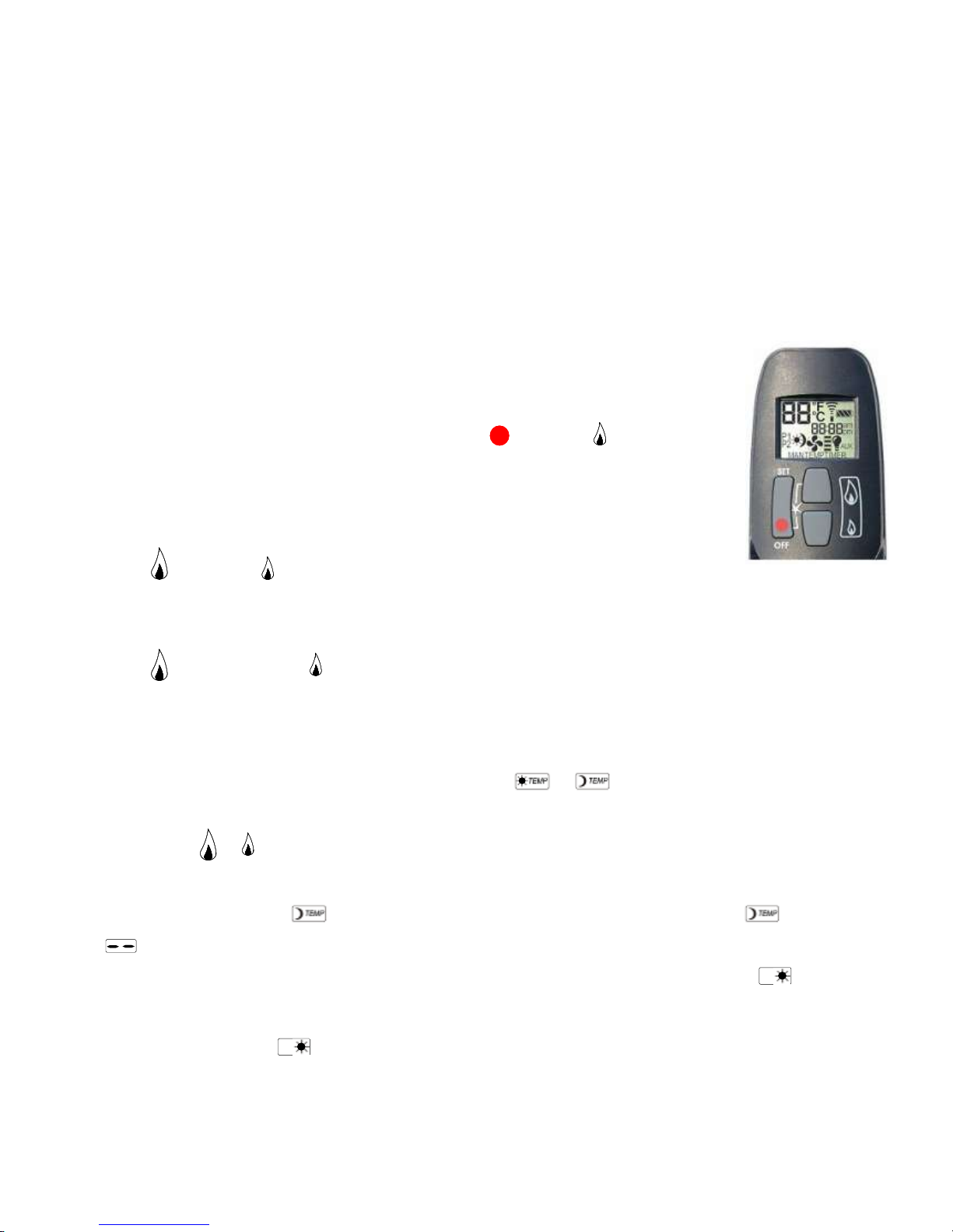
3.2 Manual transmitter
* The transmitter uses a radio-controlled signal. The signal code is set at the factory
3.3 Screen setup
* After the batteries have been inserted, press the OFF
button and (small) at the
same time to toggle between °F (and 12 hour clock) and °C (and 24 hour clock).
* Wait a moment or press OFF to return to MAN mode.
33.4 Setting the time
* Press (large) and
(small) at the same time to go to the SET mode or programming
mode.
* The time can be set while the screen is flashing.
* Press to set the hour and minutes.
* Wait a moment or press OFF to return to MAN mode.
3.5 Setting the timer: P1 and P2
* Briefly press the SET button to select the required mode
or
* Keep the SET button pressed until the screen starts flashing.
* Then press or to set the required temperature.
* Wait a moment or briefly press the OFF button to select the MAN mode.
* If the temperature setting also needs to be switched off (to reduce battery use), turn it down until
appears on the screen.
* Once the temperatures have been set, the programme can be set by pressing the SET button. Programme
will appear. Keep the SET button pressed to set the time for the first on and off programme.
Set the time you want the unit to switch on. Then press the SET button to switch the unit off.
* Press SET again for the programme.
Set the time you want the unit to switch on. Then press the SET button to switch the unit off.
* Press SET again to see the current programme on the display.
Manual transmitter
P1
P2
Page 6
Page 6
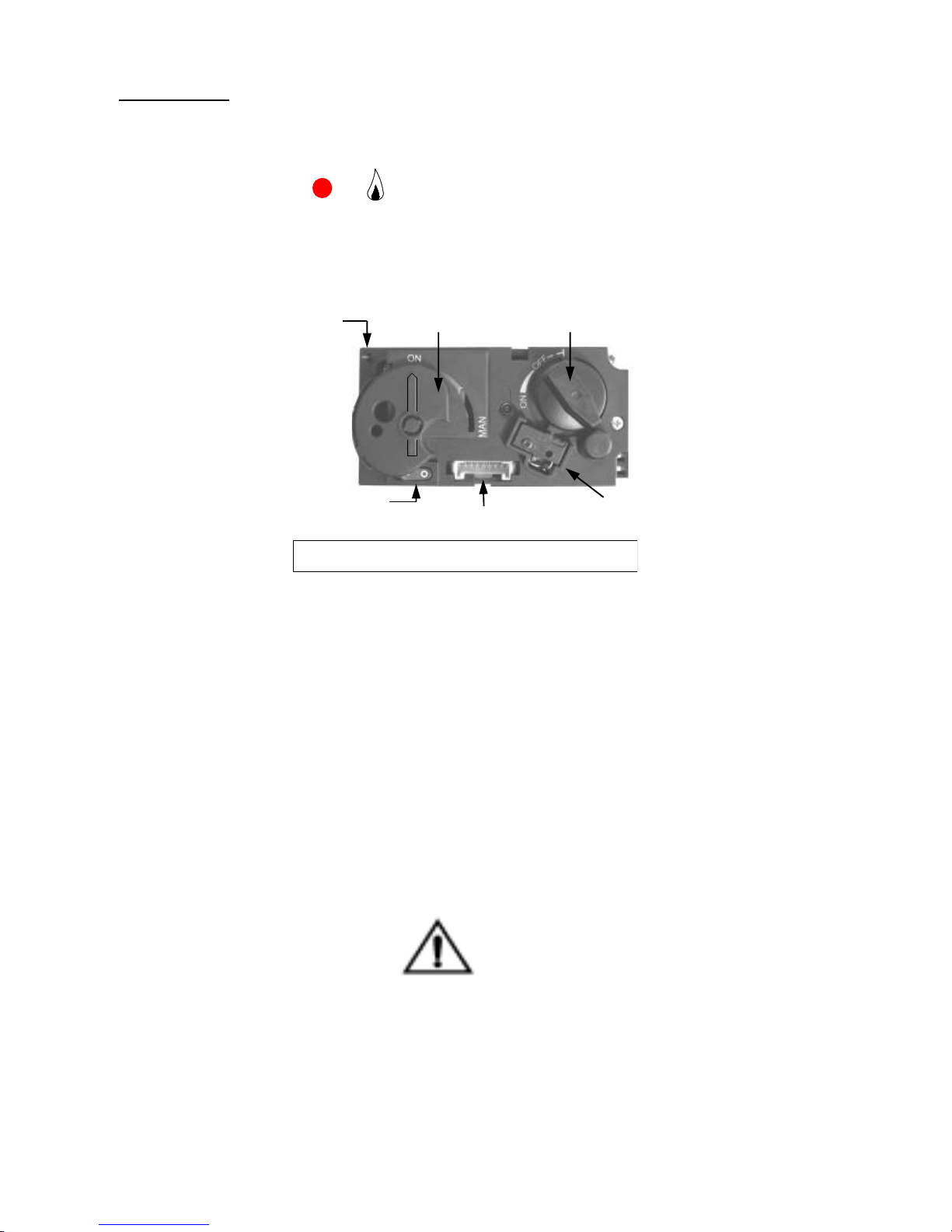
3.6 Controls (Remote Control)
Igniting the fire
* Open the gas shut-off cock that has been installed in the gas pipe to the unit.
* Press the “O I” switch, on the gas control block, in the “I” position.
* Turn the operating button on the gas control block, into the ON position.
* Simultaneously press OFF and (large) on the manual transmitter. A short sound signal will confirm
commencement.
Short sound signals will then follow until the pilot flame and main burner are ignited.
After the main burner is ignited, the flame size will automatically move into the maximum setting.
3.7 Possible error messages
* Long sound signals during the ignition: Receiver batteries are almost empty. (After this signal occurs, the
unit can be switched on approximately another 10x).
* 5 seconds of continuous sound signal: Error message. For example: one of the cables is not connected, the
“O I” switch is not in the “I” position.
* 5x short sound signal: Ignition of the pilot flame and main burner is unsuccessful.
Possible cause: air in the pilot pipes.
Important
If the pilot light extinguishes, one should wait at least 5 minutes
before repeating the aforementioned steps.
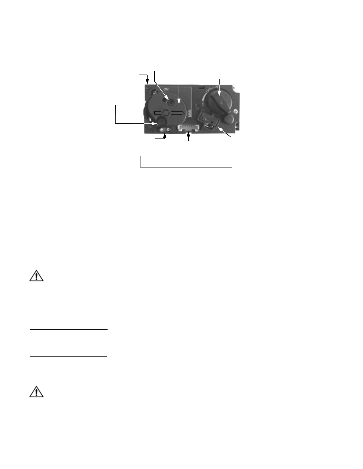
Piezo connector
(With manual
operation)
Control button
Motor button
(in the maximum setting)
Microswitch
“O I” switch
8-pole receiver cable
connection
Gas control block (Operating button in ON-position
Page 7
Page 7
3.8 Setting the flame size / Extinguishing the fire
* After the burner is ignited, the flame size will automatically move into the maximum setting.
* Press (small) to reduce the flame size and turn off the burner.
(Extinguishing the fire: “STAND BY”). (Pressing the key for a short time gradually reduces the flame).
* Press (large) to increase the flame. (Pressing the key for a short time gradually increases the flame.)
3.9 Switching the unit off
* Press
to reduce the flame size and turn the burner off (“STAND BY”).
Then press OFF to turn the entire unit off, including the pilot flame.
* If the unit is not used for an extended period of time, you can turn the “O I” switch, on the gas control
block, into the “O” position, in order to save battery life.
* In this case, it is also recommended you close the gas shut-off cock in the supply line.
Breakdowns:
* If the signals from the manual transmitter are not received adequately by the receiver, this may be caused
by:
1. Flat batteries: replace the batteries.
2. An electronic problem: can be solved by pressing the “RESET” key on the receiver.
3. Contact your fitter if the unit regularly turns off.
Important: If, for whatever reason, the pilot light extinguishes, you must wait 5 minutes before igniting
the pilot light again.
3.10 Inserting and replacing the batteries
* The batteries of the manual transmitter and receiver have a life span of approximately one year. The use of
alkaline batteries is recommended.
* The batteries need to be replaced when the following occur:
1. Manual transmitter: BATT appears on the display.
2. Receiver: long sound signals can be heard during the ignition.
1. Manual transmitter:
* Open the small lid on the back.
* Carefully remove the 9V block battery and loosen the battery from the contact holder. Do not pull the
wires!
* Connect the new battery and place it back into the transmitter. Close the lid.
2. Receiver:
* Carefully remove the entire receiver from the holder.
* Slide the small lid open.
* Remove the batteries from the battery holder.
* Place 4 new 1.5V batteries (type LR6 or AA) in the battery holder in the indicated manner. The spring
always needs to be against the minus (-) pole of the battery.
* Close the lid and place the receiver back into the holder.
Incorrect placing of the batteries can irreparably damage the electronics or power.
Only replace the batteries when the unit is completely turned off.
Important
Only remove batteries using non-metallic tools.
Removing batteries with a metal object may damage the electronic control permanently.
Page 8
Page 8
4.0 MANUAL OPERATION (in case of emergency, only if remote control is not working)
The unit may be operated by hand if there is a defect in the remote control. To do so, the ignite (piezo)cable of
the receiver must first be removed and carefully slid into the piezo connector on the gas control block.
4.1 Igniting the fire
* Open the gas shut-off cock that has been installed in the gas pipe to the unit.
* Press the “O I” switch, on the gas control block, in the “I” position.
* Turn the motor button, on the gas control block, completely to the right. The button will make a "click”
sound.
* Turn the operating button on the gas control block, into the “MAN” position. A metal circle in the
operating button will become visible.
* Push the metal circle inwards. For example, with a pen. Gas will now flow to the pilot flame.
* While keeping the metal circle pressed down, press the (square) piezo button (along the “O I” switch)
several times to ignite the pilot flame. You will be able to see whether the pilot flame is burning through
the glass window.
* If the pilot flame is alight, keep the metal circle pressed down for another 10 seconds and then let go.
Important: If the pilot light extinguishes, one should wait at least 5 minutes before repeating the
aforementioned steps.
* Turn the operating button to the ON position. The burner may or may not ignite, depending on the position
of the motor button.
* By turning the motor button to the required setting to the left, the burner will ignite and the flame size can
be adjusted.
4.2 Extinguishing the fire
Turn the motor button, on the gas control block, completely to the right. The button will make a "click” sound.
The burner will turn off. The pilot flame continues to burn.
4.3 Switching the unit off
Press the "O I” switch, on the gas control block, in the “O” position. The pilot flame will extinguish.
If the fireplace is not used for an extended period of time, we recommend closing the gas shut-off cock in the
supply line.
Important: If, for whatever reason, the pilot light extinguishes, you must wait 5 minutes before
igniting the pilot light again.
Piezo Button
Piezo connector
(With manual operation)
Control button
Motor button
(in the maximum setting)
Microswitch
“O I” switch
8-pole receiver cable
connection
Small metal circle for
manual operation of the
ignition
(Control button in Manual position)
Page 9

Page 9
5. INITIAL START-UP
The unit has a layer of heat-resistant varnish that resists very high temperatures. An unpleasant smell may
develop in the first hours after starting the unit due to burning in of the varnish; however, this is not dangerous.
To accelerate this process, allow the unit to burn at the highest setting for several hours and ventilate the
area well. After the first time the unit is turned on, a light deposit may form on the inside of the window. This is
due to the varnish hardening. After the fireplace has cooled down, this deposit can be removed using a fireplace
glass cleaner or ceramic hotplate cleaner.
5.1 Daily maintenance
* Avoid having a lot of dust and cigarette smoke, candle and oil lamp particles in the air of your home.
Heating of these particles through the convection system of the unit, can lead to discolouring of walls and
ceilings. It is therefore advisable to ensure the area containing the unit is always sufficiently ventilated.
Regularly remove any dust that has settled behind the operating lid with a vacuum cleaner.
If the glass is broken or cracked, it should be replaced immediately by a recognised fitter before the
unit is used again.
* The unit must be switched off immediately if something is spilt on it. It should only be cleaned once the
unit has cooled down. Never use abrasive, aggressive cleaning products or fireplace cleaner; only use a dry
cloth that does not give off fluff.
* Your local specialised dealer will be able to provide you with spray cans containing heat-resistant varnish,
so that small stains or damages may be touched-up during annual maintenance.
5.2 Important tips for gas heating or wood fuelled units and fireplaces.
Prevent discolouration of walls and ceilings!
There are always particles in the air in each living area even if the area is vacuum cleaned regularly!
These particles are easily visible when the sun streams in. This issue will not arise if the amount of
particles in the air is limited. If these particles are present in greater quantities and particularly if the air is
contaminated by soot and tar particles, for example, through the burning of candles or oil lamps and
cigarette or cigar smoke, then we can speak of a poor inner climate! Cooled air slowly flows over the floor
to the heater in a heated living area. This air is heated in the convection system of the fireplace or heater,
resulting in a quickly rising column of air that subsequently spreads through the room again. This means
there is always dust and other polluting particles depositing on cold and often damp surfaces. This issue
occurs especially in a new building (building damp) that is not yet dry. An undesirable consequence of this
phenomenon could be discolouration of walls and or ceiling!
How can this problem be avoided?
* With a newly built fireplace or following renovation, wait at least 6 weeks before firing up.
* The building damp must have disappeared completely from the walls, floor and ceiling.
* The room where the unit is located must be well ventilated.
* The required air ventilation must be in line with local building regulations.
* Limit the use of candles and oil lamps and keep the taper as short as possible.
* These two creators of atmosphere ensure considerable quantities of polluting and unhealthy soot particles
in your flat.
* Among other things, cigarettes and cigars contain tar that will precipitate on cold and damp walls during
heating.
* This may occur above radiators and light fittings and with ventilation grilles (if there is a poor internal
climate), although to a lesser degree.
Page 10
Page 10
6. INSTALLATION INSTRUCTIONS
6.1 General instructions
* The gas fireplace must be installed, connected and inspected as a closed unit by a qualified fitter, according
to national, regional, and local standards and regulations.
* The flue tube system and the outlets in the outer wall or roof face must also meet the requirements outlined
in the applicable standards and regulations.
* The temperature of the walls and shelves near the side and back of the unit may not be more than 80°C
higher than the temperature of the environment.
* The unit has been approved in combination with the THC CC and US concentric flue system Ø100/Ø150
mm or Ø130/Ø200 mm, in accordance with European CE standards for gas units, and may therefore only
be applied with this system.
* The unit needs to be inspected by the fitter for local gas distribution (gas type and gas pressure) as indicated
on the identification plate.
* The instructions are only applicable if the relevant country code is stated on the unit. If this is not the case,
the gas technical information for the relevant country needs to be consulted and modifications discussed
with the manufacturer.
* There will be air in the gas pipes when the unit is first used. The gas pipes therefore need to be vented first.
* Ignite the heater according to operating instructions and check whether the burner flame is uniform. After
the unit has been used for the first time, you should remove any deposits resulting from convection-curing
of the unit, from the glass window using a glass cleaner for heaters.
Warning:
Never install the unit against or within a flammable wall!
Distance to flammable materials:
* With respect to the front, side and top of the unit, a distance of 1000 mm needs to be kept between the unit
and: curtains, floor covering, upholstery and fabrics, and/or other flammable material unless stated
otherwise in these instructions.
Distance to non-flammable materials:
* The unit needs to be placed a minimum distance of 25 mm from the wall unless stated otherwise in these
instructions.
Important
* Construction material for fireplaces and mantles etc., or for an assembly must be made of non-flammable
material. This also applies to floors and ceilings. Never use flammable materials near the unit in
compliance with the abovementioned instructions.
Note: Please contact your supplier if you are unsure.
Important
The installation may only be performed
by an authorised person
Page 11

Page 11
7. CONCENTRIC FLUE SYSTEM CC
The concentric flue system consists of a 100mm or 130mm Ø inner flue concentric with a 150 mm or 200 mm Ø
outer flue. These flues have been set up concentrically; the combustion gases are exhausted through the internal
flue while the fresh combustion air is supplied between the internal and external flues.
7.1 Components of the concentric flue system. (See page 29,30 and 31)
Different connections are possible using the concentric flue system. These are:
Through the roof face and through the exterior wall.
There are various options for mounting the pathway for this system,
however, there are a few important requirements/conditions:
* The maximum allowable vertical flue length is 12 metres (the sum of the flue length and the calculation
lengths for the bends).
* 90° bends have a 2-metre horizontal calculation length.
* 45° bends have a 1-metre horizontal calculation length.
* The outlet can be installed at any point on the roof face or exterior wall (supply and discharge in an identical
pressure area), but must meet applicable regulations.
* Duct pathways may not be insulated
Important
* Ensure the restriction plate is mounted in the correct manner, as indicated in these instructions.
* The correct restriction plate will provide the unit with the most optimal efficiency, flame image and
combustion.
* Mounting an incorrectly placed restriction plate may cause malfunction of the unit.
7.2 Construction of concentric flue system CC
Indirect wall connection.
* The outlet may also be installed above the exhaust in the wall, taking any hindrance to the surrounding area
into consideration, according to national, regional, local standards and regulations. Ensure wind pressure on
the flue terminal is not too extreme, such as a balcony, flat roof, corners and in small alleys etc., as this may
negatively influence the unit efficiency.
* Provide a recess in the exterior wall of around 155 mm for concentric 100-150, and 205 mm for concentric
130-200. (in a flammable wall ensure there is 50 mm of extra space around the outer pipe and use
fireproof casing) and fix the exterior wall duct with the wall plate to the outer side of the wall. The wall
plate of the exterior wall duct must be sealed sufficiently against the wall on the outside, to avoid moisture
and/or flue gas leaks into the living space.
* The flue should be cased if necessary. Sufficient fireproof measures must also be taken when the flue is
being mounted along flammable materials.
* Determine the position of the unit and outlet and begin construction of the flue with the connection on the
unit, paying attention to the direction of installation and connecting the elements by means of clamp strips.
* The fitted pipe can be used between the bends or when connecting to the unit.
If necessary, use wall brackets to support the flue
Mounting using the roof pass-through option
* The flue terminal can be located at any random place on the roof face (supply and exhaust in identical
pressure areas) and must meet the applicable rules and regulations.
* A roofing sheet for a flat roof or a roofing sheet lead for sloping tiled roofs can be used for a watertight duct.
Use various bends for the slope, if required. The recess in the roof decking should be 5 cm larger all
around, to ensure sufficient fire resistance.
* One needs to take into account the regulation regarding fire resistance between rooms (See national,
regional, local standards and regulations). A casing made of fireproof material (e.g. 12 mm Promatect fire
resistant plate) must be used at 25mm from the outside duct.
* Determine the position of the unit and outlet and begin construction of the flue with the connection on the
unit (always 1 metre vertical first), paying attention to the direction of installation! The inner flue must be
installed for draining purposes. Connect the elements by using clamping strips. Ensure the gas tightness of
all connections is correct.
* A fitted pipe can be used between the bends or when making the connection to the unit and/or the roof pass-
Page 12
Page 12
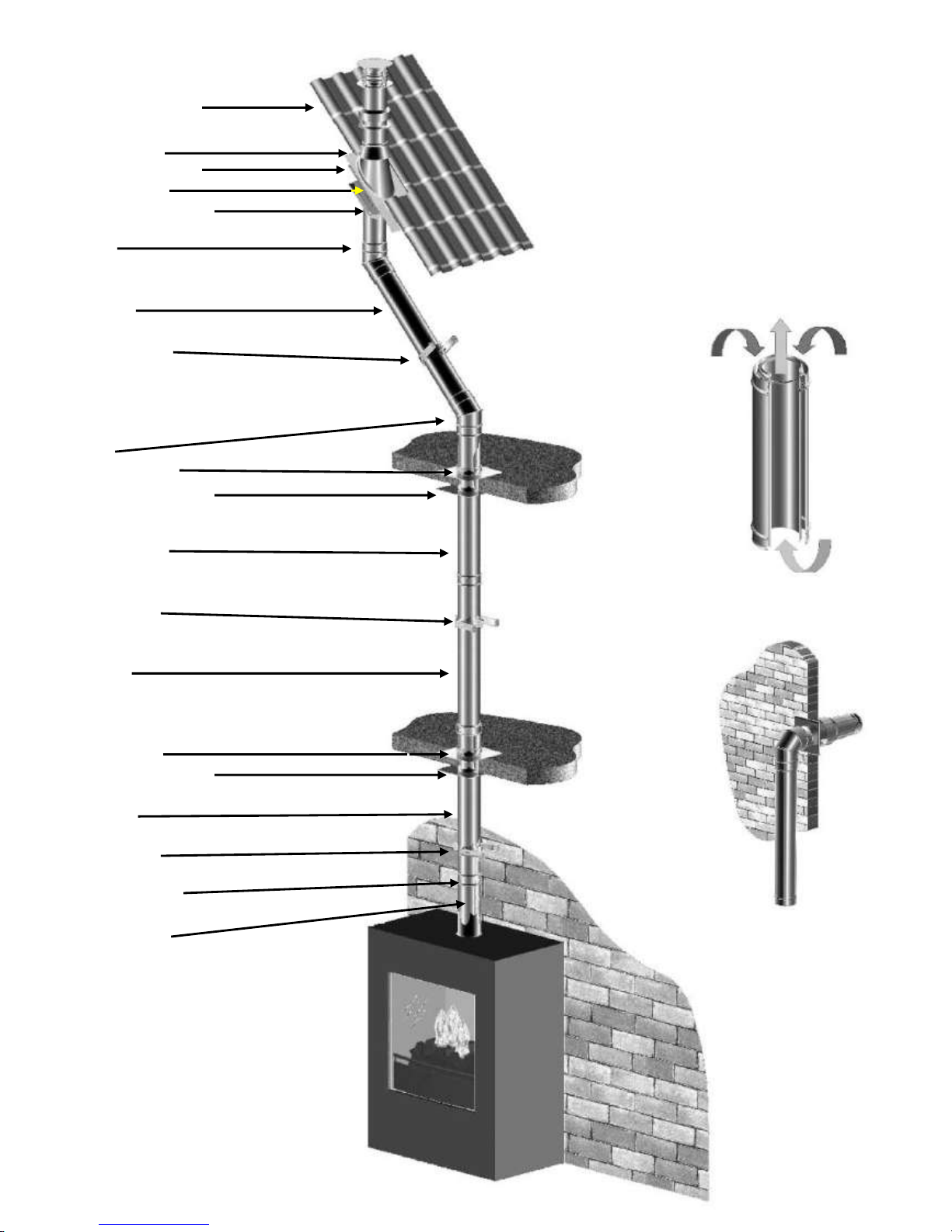
Roof-pass trough
Storm collar
Lead roofing sheet
Roof bracket
Fire protection plate
Bend
CC Pipe
Wall bracket
Bend
Floor support
Fire protection plate
CC Pipe
Wall bracket
CC Pipe
Floor support
Fire protection plate
CC Pipe
Wall bracket
Clamping strips
CC fitted pipe
Page 12
Page 13

Page 13
7.3 Installation instructions regarding existing flues.
Instructions
The flue gas exhaust system falls within category C91 and must be built in accordance with national rules and
regulations and the instructions of the manufacturer, as specified in the documentation and installation instructions.
This means, among other things, that the chimney pass-through must not be smaller than 150 mm round / square, but
no larger than 200 mm, and not ventilated by grilles etc. In the case of larger chimney pass-throughs, a flexible hose
of around 150 mm may possibly be used in combination with a flexible hose of around 100 mm, as described below.
For other situations, you should consult your supplier / manufacturer.
7.4 Parts (See page 14)
Check all parts for damage before commencing the installation. You will require the following parts for converting a
brickwork duct to a concentric duct connecting to a CC duct system :
1. Clamping strips 7. Chimney mounting plate (renovation kit)
2. CC Fitted pipe 8. Clamping strips
3. Clamping strips 9. Roof pass-through
4. Inner mounting plate
5. Slider (renovation kit)
6. Flexible hose 316 L round 100 /107
Note: The renovation/sanitation set consists of parts 4, 5 and 7.
7.5 Installation (See page 14)
·* Guide the flexible hose (6) through the existing duct (8).
·* Attach the adapter (5) to the bottom of the flexible hose and secure this in place using 2 parkers.
·* The mounting plate (7) is adjustable, slide / fix it on to the outer pipe and then mount it against the ceiling
(airtight).
·* Shorten the flexible hose to approximately 100 mm above the chimney coping plate.
·* Attach the mounting plate / connecting piece (7) to the flexible hose on the roof. clamp it with a hose bracket
and secure it in place using a parker.
·* Attach the mounting plate / connecting piece (7) to the chimney coping watertight on the roof using silicone
sealant and stainless steel screws.
·* Install the roof pass-through (9) and secure it in place using the supplied clamping strips (8).
·* Position the unit in accordance with the instructions of the unit manufacturer.
·* Always install a minimum of 1 metre of concentric duct type CC/US 100-150 (2), or 130-200 mm with
reduction to 100-150 mm.
7.6. Cleaning and maintenance.
The unit must be cleaned and checked every year by your dealer. The Concentric flue system must be cleaned every
2 years.
Control of:
1 Density of the gas products of combustion and combustion air feed circuit.
2 The correct operation of the gas control block and the ignition of the burner.
Carry out the checks in accordance with the inspection list on page 22.
Page 14

Page 14
9. Roof pass-through
8. Clamping strips
7. Chimney mounting plate
(Renovation kit)
6. Flexible hose 316L
5. Slider (renovation kit)
4. Inner mounting plate
(Renovation kit)
3. Clamping strips
2. CC Fitted pipe
1. Clamping strips
Page 15

Page 15
8. Instructions for the Mertik Maxitrol GV60 and the Remote Control:
Ensure that the fuel supplied to the unit is clean and free from particles and moisture.
Before a gas supply pipe (new or existing) is connected to the main gas pipe at the gas meter and to the gas
control block of the unit, clean and dry compressed air should been blown through it.
Cut copper pipes as well as aluminium pilot pipes must be deburred and blown clean before they are
connected. The dust filter at the connection to the gas control block will only filter out the coarsest dirt
from the system. Fine particles are still able to reach the inside and may damage and/or adversely affect
regulation in the gas control block .
Heat, moisture and dust are a threat to all electronic components
Protect the electronic gas control until all construction, plastering and paintwork has been completed. If
such work cannot be avoided, then protect the control against dirt and moisture penetration by using, for
example, plastic film .
Warning
Electronic components will become permanently faulty when exposed to temperatures higher than 60°C.
Standard AA batteries will crack open at temperatures >54°C and the battery contents will damage the
electronic switches located underneath. Batteries last longest at <25°C. At >50°C the life span is around 23
weeks, this makes the use of the gas fire unnecessarily expensive.
Only install the gas control block and receiver as pre-installed at the factory
Remember that components may have to be replaced or that repairs may have to be performed at a later
date.
This may be more difficult if the control is installed using a method that is different from the instructions
provided here.
Please note!
Only place the batteries after wiring to the receiver, gas control block and pilot set is connected.
Premature connection to the energy source may damage the control’s CPU (central processor).
Ensure that the ignition cable is not near the antenna wire and that they do not cross each other.
The high voltage released at ignition may damage the sensitive receiver circuit.
This may mean that the unit becomes less responsive or not responsive at all to handset commands. (See
photograph 1 on page 16)
If the manual transmitter range is too limited, loosen the antenna wire from the terminals on the
receiver box. Direct the antenna wire away from the ignition cable and in the direction of the control
box door.
Ensure there is no contact with metal components. Ensure there is no damage to the connection to
electronic components or to the wire itself. (See photograph 1 on page 16)
Connect the wires correctly to the contact breaker behind the gas control block.
The shortest wire runs immediately back to the 1/0 switch and can be found nearest to the back of the gas
control block. The longest wire runs to one of the two connections on the receiver box and only fits on one
of the screws .
Do not tighten the contact breaker and the thermocouple connection too tightly on the gas control
block or to each other.
It is sufficient to tighten by hand and add a half a turn with an open-end spanner. Tightening too much
will break the connection to the magnetic coil below and/or the insulation around the aluminium contact
pin in the contact breaker. This may lead to the magnetic coil not opening the gas supply to the pilot and
the unit not working.
Page 16

Page 16
Do not extend the thermocouple supplied to the pilot set
Extending the thermocouple beyond its limit will lead to a reduction in voltage. This may, in turn, lead to
the magnetic coil not being activated.
Do not extend the thermocouple supplied to the pilot set
Extending the thermocouple beyond its limit will lead to a reduction in voltage. This may, in turn, lead to
the magnetic coil not being activated.
The receiver and the control units on the gas control block should be switched on to ensure automatic
start-up through the manual transmitter.
The oval disk on the gas control block should be turned to the ON position. The 1/0 switch should be set to
1. See photograph 2. The ignition cable should be connected to the SPARK connection point on the
receiver box. See photograph 1.
The manual transmitter has to communicate with the receiver. This has to be ‘learnt’.
Press the RESET button using a blunt object. (See photograph 3.) Continue to press this button until you
hear a short beeping sound, followed immediately by a long beeping signal. Release the button. Direct the
manual transmitter towards the receiver and press the arrow down until you hear a long beeping sound. The
gas control button will now move for a short period.
The manual transmitter has now learned the setting with regard to the receiver and the unit can now be
ignited using the remote control. If the manual transmitter is still not communicating with the receiver,
repeat the procedure again.
The system’s thermostat sensor is in the manual transmitter.
The manual transmitter operates best at a distance of 2 or 3 metres from the unit. Although communication
occurs via short wave radio signals, it is recommended to place the hand transmitter in view of the gas
apparatus in a place where the user wishes to experience a pleasant temperature. Do not place the manual
transmitter in direct sunlight or other warm location. The thermostat measures the temperature and
regulates the flame size of the gas unit accordingly.
Remove the batteries only with the red ribbon underneath the batteries, not with a metal tool
Removing batteries with a metal object may damage the electronic control permanently.
Photo 2
Photo 3
Photo 1
40 mm
Page 17

Page 17
8.1 Mertik GV60 Troubleshooting Flow Chart
No ACTION Possible problem/cause Solution
1.
Option: wall switch START:
press ON button > wall switch
works.
NO
Bent pin on switch, or cable not
operating properly.
Straighten pin, replace wall switch
or cable.
1.
Manual transmitter START: press
both buttons to start ignition
sequence.
Beep will occur each second
NO
Manual transmitter battery low. Replace battery, 9V quality
alkaline!
Receiver batteries low. Replace batteries, 1.5V AA quality
alkaline!
Optional mains adapter not
operating properly.
Check mains adapter.
Check coding of transmitter and
receiver.
Learn in new code, see instructions
and label on receiver.
OK
Transmitter/receiver range
limited.
1. Move antenna cable, see
instructions.
2. Replace receiver.
Optional wall switch / cabling not
operating properly.
Replace wall switch / cabling.
Receiver fuse blown (in older
versions only).
Replace receiver.
2.
Magnet unit in gas valve is
energised (audible click)
NO
No beep Impulse magnet not operating
properly.
Replace gas valve.
NO
3 short beeps Receiver batteries low. Replace batteries, 1.5V AA quality
alkaline!
NO
1 long beep ON/OFF switch on gas valve in
OFF position
Set switch to ON.
8-wire cable between receiver and
gas valve defective / poor contact.
Check cable, especially in case of
plug connection.
OK
Switch cable disconnected. Check switch cable, see fig. 1 on
page 18
Motor not operating properly. Replace gas valve.
Micro switch on gas valve not
operating properly.
Replace gas valve.
Page 18

Page 18
No ACTION Possible problem/cause Solution
3.
NO
Ignition components not operating properly. Check connection between cable & IGN
electrode.
Check IGN electrode spark gap.
Check IGN electrode for discharge to ground
(break in ceramic).
Check IGN cable for damage
Increase distance between IGN cable and all
metal parts. Check that spark does not
discharge to ground at location of spark plug
connection. Shorten cable if possible. If
applicable, provide extra insulation with silicon
hose etc.
Spark will occur each
second.
NO
IGN sequence stops, no pilot flame.
No reaction to transmitter command (receiver
does not react).
Press RESET button, see instructions.
Add ground wire between pilot burner and gas
valve.
Do not coil the IGN cable.
Shorten IGN cable if possible.
NO
IGN sequence stops, no pilot flame.
Transmitter command is possible.
IGN sequence stops, no pilot flame.
Transmitter command is possible.
OK
4.
Pilot lit.
NO
TC and SW cable reversed. Check connection of cable to receiver and
interrupter, see fig. 1.
Impulse magnet not operating properly. Replace gas valve.
Short between interrupter and SW cable. Check connection to interrupter.
OK
No gas (magnet unit drops after 30 second
audible count).
Check gas supply to gas valve.
5.
Sparking stops after pilot
is lit
NO
Short between interrupter and TC cable. Check connection to interrupter, see fig. 1
OK
Electronic measuring amplifier defective. Replace receiver.
Interrupter
Receiver
Page 19

Page 19
No ACTION Possible problem/cause Solution
6.
NO
Resistance in thermo
current circuit too high.
Check cables and connections in
thermo current circuit.
Magnet unit drops
(audible click)
Not enough heat on
thermocouple.
Check position of pilot to
thermocouple and intensity of pilot
flame.
Motor turns to main gas
and pilot stays lit.
Low voltage from
thermocouple.
Check connections and, if necessary,
replace thermocouple. Do not
overtighten the connections!
Short because
thermocouple end is
damaged.
Replace thermocouple, do not
overtighten the connections!
NO
IGN sequence stops. No
reaction to transmitter
command (receiver does
not react).
Press RESET button, see
instructions.
Add ground wire between pilot
burner and gas valve.
OK
Do not coil the IGN cable.
Shorten IGN cable if possible.
7.
Main burner is lit.
NO
Gas valve manual knob in
“MAN” position.
Turn knob to “ON” position.
OK
8.
Main burner stays lit.
NO
Too much / too little air
flow / draft at pilot, blows
out or is smothered.
Check whether restriction plate has
been correctly applied in unit, see
instructions.
Poor flue location, check correctness
of layout and connections.
OK
9.
Magnet unit drops while
motor turns.
3 beeps
NO
Receiver batteries low. Replace batteries, 1.5V AA quality
alkaline!
System can be switched
OFF via remote control.
NO
System can be
switched OFF via
ON/OFF switch.
NO
Short between TC and SW
cable.
Check connection to interrupter
block.
YES
YES
OK OK
Replace gas valve.
Page 20

Page 20
Page 21

Page 21
Name
Address
Unit serial number
Date of purchase
Installation date
Comments
9.0 MAINTENANCE CHECK LIST
Fitter details:
Service date Performed by Work activities performed
Service and maintenance log book:
Page 22

Page 22
10. Maintenance activities. .
Please note: turn off the gas supply and power supply as much as possible during maintenance activities.
Maintenance activities should be performed by a qualified fitter.
Close the gas tap while maintenance activities are being performed.
Inspect
Work activities OK
1 General inspection a The main burner should ignite smoothly (within several seconds) and not give a bang sound due to
delayed ignition. Go to number 7 if there appears to be delayed ignition.
b Check the flame image. No flames against the glass. The flame image should be stable.
The flame should be yellow after approximately 15 minutes; go to number 7 if the flame image is
blue.
c Check for excessive formation of soot on the inside of the glass/combustion chamber and on decora-
tive parts.
Go to number 7 if there is excessive formation of soot.
2 Door/front a check for obstructions in the convection air openings
3 Glass window, seal. a check the glass window for cracks etc. Replace if damaged, cracked, or broken.
b check the seal of the glass window; this needs to join the unit and glass window. Replace if required.
c check any hinges, seals, quadrants etc.
d clean the glass. Check there is an even (not too large) load on the glass window. Prevent point load.
4 Gas control compart-
ment and convection
part of the unit
a clean these areas with a vacuum cleaner. Do so carefully. Remove parts that do not belong here.
b check if the convection airflow is free.
5
a remove decorative parts and clean the burner (be careful with ceramic burners!) with a vacuum
cleaner.
Decorative parts (logs/
pebbles etc.) and
(pilot) burner
b inspect decorative parts for damage/cracks/discolouration and clean with a soft brush if required.
c check if the burner cover is intact and free of corrosion. Replace the burner if required.
d after completing the inspection: replace decorative parts, exactly as stipulated by the manufacturer.
Ensure the pilot burner is kept free!
e check if the pilot flame protection is intact (if applicable).
f check the piezo for sufficient spark power, and ensure the ignition cable is free from metal parts/
electrical parts.
6 Combustion chamber a check the condition of the finishing, such as varnish and enamel. Check for corrosion. Repair if re-
quired.
b
replace the unit if there are holes. Close the unit for further use.
c check overpressure hatches or overpressure construction for sealing and sufficient movement/deposits.
7 Ignition and operation
of the main burner
a remove the burner from the unit and check whether the main injector is dirt-free.
b check if the primary ventilation opening in the main burner is dirt-free.
c mount the burner and check if the burner is in a good position in relation to the pilot burner.
d check if the burner is fixed and cannot move.
e check if the pilot burner burns well, with a blue flame (blue only).
f check if the burner ignites uniformly across the entire surface and without significant delay.
g check if the flame image is uniform and stable.
h check the initial and burner pressure. Do not forget to close the pressure measuring points.
i check if gas control parts are intact, and that plastic parts have not melted, for example.
j check electrical wiring for damage and ensure they are away from hot parts of the unit.
8 Installation a
check if convection grates are dust-free and dirt-free.
b check if there is sufficient distance between the unit and flammable furniture.
9 Flue tube/air supply a where possible, inspect the general state of the exhaust/supply system and check for blockages /
leaks / corrosion.
b check the outlet, which should be free from dirt and blockages.
c check the outlet, which should be free from dirt and blockages.
10 Remote control a check for correct functioning of the remote control.
11 Ventilators (if present) a clean the convection ventilators and check for correct functioning.
Page 23

Page 23
11. PLACING THE UNIT (first read “General instructions”)
Please note: Before placing the unit, we recommend you first read Chapter 7
“Concentric flue system” on page 11.
11.1 Connection to the gas pipes (see page 25 for details)
You can determine where the gas pipes will be placed, dependent on the layout. Ensure control equipment is not
twisted during installation and there is no excessive tension. Accessibility of various connection points in relation
to components need to be maintained. After installation, check the connections for tightness in relation to gas.
Use a 1/2“ gas tap with connection. Ensure the gas pipes are dirt-free and sand-free, and gas and
combustion products from various parts and functioning is correct. The gas connection should only be
undertaken when the electricity supply is disconnected. This prevents any damage occurring to the gas control
equipment.
11.2 Preparation and installation of the unit (see also pages 30 + 32 + 33)
Remove the packaging and check the unit for possible damage.
Please note: place the unit on a stable surface.
Do not place the unit on its back or on its side!
Place the unit at the installation location
The 2 front main windows should now be removed in order to take the additional parts out of the unit.
The side window(s) can remain in place.
Loosen the screws of the lower and upper quadrants.
Remove the glass strip gently from his seat possibly with a screwdriver.
See example on Page.31 Figure B and C
Next, take the packaged components out of the unit and check to make sure they are not damaged or
broken.
Situate the unit (see page 32 figures H, I and J as an example of an installation location) in your chosen
installation location . At the rear and the sides, the unit must have at least 25 mm clearance from fireproof
built-in materials. Install the supplied convection grilles at least 50 cm below the ceiling (see page 30
figures 3/4/5 C) on the appropriate wall. A lowered ceiling inside the whole structure could be a possible
solution in the event of a situation with a visual obstruction.
The legs (page 31, figure F) of the unit can be adjusted for 90 mm, and if necessary shortened, see also
dimensional drawings. The adjustable feet allow fine adjustments (levelling) to be made.
Gas pipe, thermocouple and ignition cables have been placed in coils under the unit. Cut the binders and
CAREFULLY unroll the various lines and cables to the position where the gas control cassette is to be
placed.
Fixing to the wall is effected by means of adjustable wall brackets (see figure E page 31) on top of the unit.
Fastening materials are not included.
Now determine the installation and assembly of the CC ducts and accessories. Please refer to Chapter 7.
”CONCENTRIC FLUE SYSTEM CC” on Page 11 and “Table of concentric pathways “ on Page 28.
With the supplied suction cup you can remove the windows easily.
Take hold of the front window by its sides and move it CAREFULLY upwards, then CAREFULLY and
slowly pull the bottom of the window towards you. Next, lower the window and leave it in a safe place where
it cannot be broken or damaged. Please note: the window is very fragile. You should therefore be very careful when (re)installing the window. See example on Page.31 Figure D
Please note:
The distance between the gas cassette / control cabinet and the unit will be determined by the cable / thermocouple / line lengths from the control cabinet to the pilot burner and main burner.
The max. distance is approximately 800 mm. (see also page 31 figure G). The pipes, cables and/or
couplings etc. should only be connected when the electricity supply is off.
Page 24

Page 24
11.3 Fitting the ceramic log set (see page 35 to 38)
Attention! Before placing the Ceramic log set.
With use of gas category G25 20-25 mBar (I2L, I2ELL) mount the primary aeration bracket under the burner
setting for a good fire image.
method:
* Take the Decoration plate and burner out from
the unit.
* Remove screws from the burner at the venturi.
* Mount the aeration bracket with the removed
screws on the burner as shown.
* Return Burner and decorations back in place.
Please note: when installing the log set and the various glowing materials and accessories, the
following must be taken into account:
* Keep the opening between the burner and the burner plate free of glowing material
* There should be no glowing material in or on the pilot burner.
* Ceramic materials should not come into contact with the cord of the window fixture.
Remove this if necessary. The window may otherwise be damaged.
* Mix the glowing material (lava granules) and the “fusilli” (spiral-shaped ceramic material) and spread them
evenly over the burner and the burner plate so that they are just covered. Glowing embers can be placed
here and there as decoration.
NOTE: the remaining material can be discarded. The use of too much glowing material can adversely
affect the combustion process.
* Place the ceramic wood blocks in the correct order as shown on Pag. 33 t / m 35.
* Place the logs carefully. Other location can seriously affect the flames or malfunction of the burnproces
(explode)
* Before replacing the window make sure if ther must be a restriction plate to be placed or not.
See page 23 and "Table of concentric tracks" on page 28
* If there is a restriction is required for your situation, remove the baffle plate by unscrewing it from the front
of the plate after the plate backwards and then out to be taken. Now install the restrictor plate with two
screws and replace the baffle plate.
* Now place the two windows in reverse order as described on page 23.
MAKE SURE THE PILOT LIGHT REMAINS UNOBSTRUCTED!
Incorrectly installed ceramic wood blocks and glowing material may have a significant influence on
the fire image and the burning effect.
Page 25

Page 25
12. TECHNICAL DETAILS GV60
Model : 1080
Gas block type : Mertik GV60
Ignition : Distance operation and Piezo ignition
Gas connection : 3/8" (Internal) A=Gas intake B=Gas exhaust C=Thermocouple connection
D=Pilot burner connection
Unit category : C11-C31-C91
Pilot flame : SIT 3 flames
Combustion gas discharge
and Combustion air supply : Concentric: Ø100 / 150 mm Ø130 / 200 mm
D= Pilot burner
connection
A=
=B
C= Thermocouple
connection
B
A
C
D
Page 26

Page 26
12.1 Gas-technical specifications
Appliance has NoX class 5
AT I2H, I3B/P BE I2E+ , I3+ DK I2H, I3B/P DE I2ELL, I3B/P
FI I2H, I3B/P FR I2E+, I3+ GR I2H, I3B/P GB I2H, I3+
IS I3B/P IE I2H, I3+ IT I2H, I3+ LU I2E, I3B/P
NL I2L, I3B/P NO I3B/P PT I2H, I3+ ES I2H, I3+
SE I2H, I3B/P CY I3B/P,I3+ EE I3B/P,I2H LT I3B/P,I2H
LV I3B/P,I2H MT I3B/P, HU I3B/P,I2H PL I3B/P
SI I3B/P,I2H SK I2H
1080
G20 G25 G30/31
NO/DK/ES/PT/DE/IE/
GB/BE/FR/IT/LV/SI/SK/
EE/ HU/LT
NL/DE
NL/NO/DK/DE/ES/PT/IE/GB/
BE/FR/LV/SI/EE/HU/LT/PL/
CY/MT/IT
I2H/I2E/I2E+ I2l/I2ELL I3B/P/I3+
1x Ø8
1x Ø5 3x Ø16
20 20/25 30/37
11.1 11.6/13.6 28.7/36.6
3.5 5.2/5.9 14.4/23.4
2.6 2.6 1.3
51 51 30
1.7 1.7 1.3
8.8 8.6 8.5/7.4
9.8 9.5 9.1/7.7
1.05 1.08 0.26/0.48
7.3 7.1 6.85/5.78
GAS TYPE
COUNTRY
CATEGORY
PRIMARY AIR
PRE-PRESSURE MBAR
BURNER PRESSURE
HIGH
MBAR
BURNER PRESSURE
LOW
MBAR
INJECTOR BORE Ø MM
PILOT INJECTOR CODE
LOW CLASS BORE MM
LOAD Hs KW
LOAD Hi KW
CONSUMPTION M³/h
NOM.POWER kW
Page 27

Page 27
13. PROBLEMS AND POSSIBLE SOLUTIONS
Please first check if all guidelines were followed before attempting to solve any problems with the unit.
Warning:
Solving problems with your unit, whether gas related or electrical, must always be performed by a qualified
technician.
SYMPTOM ACTION TO BE TAKEN
The pilot flame will not
light after repeated ignition.
1. There is air in the pipes if you switch the unit on for the first time or after a
service. It will take a little while until all the air has flowed out of the pipes and
gas flows through that can be ignited. Take it away and try to switch the pilot
flame on several times in order to allow the air to escape.
2. See whether the gas pipe to the unit is open and if there is sufficient gas pressure
to the unit.
3. Check whether there are sparks between the spark electrode and the pilot. If
there are no sparks:
a) Check whether the connection between the electrode and the ignition is
broken or faulty.
b) Check whether the spark short circuits at another point or jumps.
c) Check whether the electrode is broken.
The pilot flame will not
remain alight after ignition.
1. Check whether the pilot flame is large enough to burn around the thermocouple.
If the flame is too small, you need to check the gas feed pressure. If the size of
the pilot flame cannot be adjusted, there may be an obstruction in the pilot.
2. Check whether the thermocouple interrupter is connected to the gas valve
properly.
3. Check that the gas valve is not faulty.
4. Check whether the restriction plate has been placed according to instructions
(see page 25).
The main burner goes out
when the unit is warm.
1. This can be a normal effect of the thermostat.
Check whether the pilot flame is able to heat the thermocouple adequately. If the
pilot flame is too small then the gas pipe or the pilot flame adjustment need to be
checked.
2. Check whether the restriction plate has been placed according to instructions
(see page 25).
Soot deposits on the glass. 1. Check whether the lavasplit is lying on the burner in the correct manner.
2. Check if the pilot burner is free from burner filling.
3. Check whether there is any blockage in the burner openings.
4. Check if the flue tube is functioning correctly and if the flue tube is not hindered
or blocked.
5. Check the pipe pressure.
Sharp blue flames that are
released by the burner or a
pilot that burns too wildly.
1. Check whether the restriction plate has been used.
Weak (stifling) pilot flame. 1. Check the pilot burner pressure or duct pathway.
Main burner will not burn
after the pilot burner is
functioning.
1. Check if the motor button turns and whether the batteries are empty.
2. Possible defect in the gas block.
3. Check whether the pilot flame ignites the burner well.
4. Check that the burner opening is not blocked.
Page 28

Pag.28
Table of concentric pathways
Pathway
Illustration X totaal in Y totaal in Restriction
metres metres
min* max* min* max*
1080
Indirect exterior wall outlet A-B 1 3 0 3
Roof pass-through without slope C 2 12 from 3 meter
Roof pass-through with 45º slope** D 3 12 0 4 from 3 meter
Roof pass-through with 90º slope*** E 1 12 0 2 from 3 meter
Restrictie bepaling:
Wall pass-through - 1 metre vertical, 90° bend, max. 3 metres horizontal, Wall pass-through no restriction.
Roof pass-through - 2 to 5 metres vertical + roof pass-through, fit 35 mm restriction plate.
Roof pass-through - 5 to 12 metres vertical + roof pass-through, fit 52 mm restriction plate.
A
Y
X
E
B
Y
X
C
X
D
Y
X
X1
45° bend: calculation length 1 metre
90° bend: calculation length 2 metres
* length excluding roof or exterior wall outlets. Always adhere to a starting length of 1 metre!
** Vertical: horizontal ratio X + X1 + X2 : Y ≥ 2 : 1
*** Vertical: horizontal ratio X + X1 : Y ≥ 2 : 1
Page 29

Pag.29
Diameter A B L1 LW
100-150 100 150 250/500/1000 199/448/946
130-200 130 200 250/500/1000 199/448/946
THC-CC Pipe
THC-CC Adjustable pipe
Diameter A B
100-150 100 150
130-200 130 200
THC-CC Bend 15-30-45°
Diameter A B L1 L2 C
100-150 100 150 72 42 15/30/45
130-200 130 200 90 52 15/30/45
THC-CC Bend 90°
Diameter A B L1 L2 L3 L4 L5
100-150 100 150 72 90 44 145 150
130-200 130 200 87 106 69 177 177
THC-CC Reducer diam. 100-130
THC-CC Clamping strips
Diameter A
100-150 145-160
130-200 195-210
THC-CC Wall bracket adjustable
Diameter A B C
100-150 150 208 120-175
130-200 200 260 148-203
Page 30

Pag.30
THC-CC Ceiling support
THC-CC Roof support
THC-CC Centering plate
THC-CC Centering plate adjustable
THC-CC Roofing sheet sloping 0-10°
Diameter A B
100-150 150 208
130-200 200 260
THC-CC Bracket
Diameter A B
100-150 150 249
130-200 200 300
Diameter A
100-150 150
130-200 200
Diameter A B
100-150 160 300
130-200 210 350
Diameter A B C
100-150 150 300 263
130-200 200 350 288
Diameter A B
100-150 160 550
130-200 210 600
THC-CC Roofing sheet sloping 5-25°
Diameter A B
100-150 160 550
130-200 210 600
Page 31

Pag.31
THC-CC Roofing sheet sloping 20-45° (LEAD)
THC-CC Renovation Packet
Diameter A
100-150 160
130-200 210
THC-CC Roofing sheet sloping 45-60° (LEAD)
THC-CC Storm collar
Diameter A
100-150 160
130-200 210
Diameter A B
100-150 150 50
130-200 200 60
THC-CC Wall pas-through
THC-CC Roof pass-through
Diameter
100-150
Diameter
100-150
130-200
Diameter
100-150
Page 32

Pag.32
A
Page 33

Pag.33
20mm
B
C
D
E
F
G
Page 34

Pag.34
I
J
50
20
H
Page 35

Pag.35
Page 36

Pag.36
Page 37

Pag.37
Page 38

Pag.38
Page 39

Pag.39
Page 40

Pag.40
Thermocet International B.V.
Laagerfseweg 31
3931 PC Woudenberg
www.thermocet.nl
 Loading...