

Page 1
Page.1
OPERATING AND INSTALLATION INSTRUCTIONS
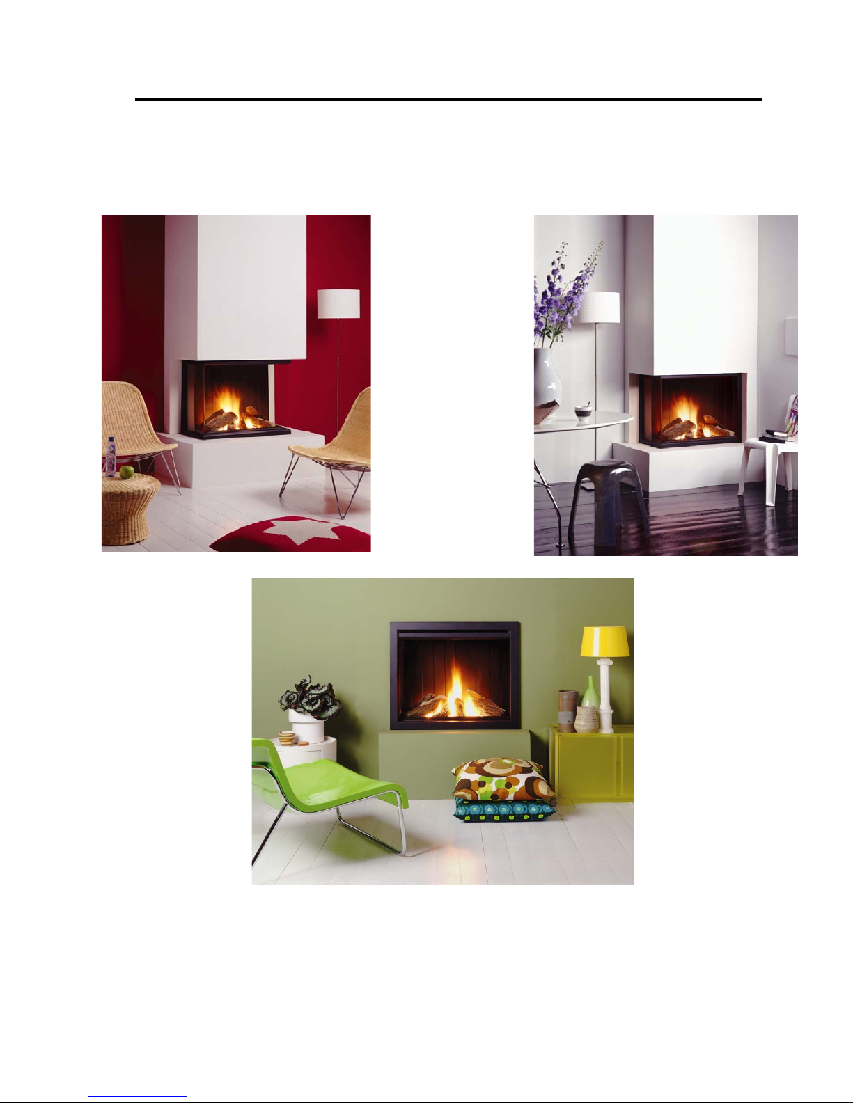
Apertura line
Page 2

Page.2
CONTENTS
1. General Page 3
Important information
Guarantee
Contents of package
2. Operating instructions Page 4
The remote control unit and its operation
Adjusting the temperature display (ºC and ºF)
Setting the required temperature
Setting the timer function
Manual flame height adjustment using various modes
Changing the battery
Connections
Technical specifications
Igniting the pilot light
Igniting the main burner
Extinguishing
Warning
Maintenance
3. Preparations for installing the Apertura Page 6
4. Installation instructions for the Apertura with concentric duct connection Page 7
General instructions
Components of the fire
Installing the Apertura
Details of the gas block rc/mc
5. Concentric duct system Page 8
Components
Connection options for concentric duct system
Structure of concentric duct system
6. Gas specifications Page 11
Diagrams Pages 12 to 18
CC DUCT SYSTEM Article numbers Page 19
Important tips Page 21
Guarantee certificate and registration card
Guarantee conditions Page 22
SUBJECT TO CHANGE WITHOUT NOTICE
(0
/13032006)
Page 3

Page.3
We wish you happy heating with the purchase of this gas fire.
Please read these instructions carefully before you install the fire and start using it.
Keep these instructions in a safe place.
Always quote type and serial number in the event of a problem.
1. General
The Apertura is delivered complete. You should inspect the appliance for damage in transit immediately on
delivery. Any damage found should be reported without delay and as precisely as possible to your supplier.
Please refer to the delivery document in this connection. Your fire is coated with heat-resistant enamel that
can withstand extremely high temperatures. Burn the fire at high during the first hours of use and ventilate
the room well. The curing of the enamel may produce a smell/smoke, but this is harmless, however.
After the window has cooled down, any marks on the glass should be removed immediately with glass
cleaner.
Important information
The Apertura must be installed, connected and inspected by a recognized installer, in accordance with national and regional standards. The appliance must be checked by the installer for gas tightness to gas and
combustion products and the correct operation of the various components and functions. In addition, the
flue system and the outlets in external walls or roof surface must comply with current regulations. The fire
falls within the category of closed appliances in an installation space, without blower and with a flue loss
in excess of 17 % (non-condensing).
Guarantee ( see page 21 and 22)
Always complete your guarantee card in full and return it to your supplier immediately after purchase.
Type and serial numbers are shown on the plate that you will find in the control box.
(See Page 12 diagram 1-14).
Contents of package
1 x Completely mounted appliance: Front, Corner or Panorama
1 x Flexible gas hose
4 x Adjustable feet
2 x Stabilizer plate
4 x Bolts M6 x 10
4 x Bolts M6 x30
8 x Nuts M6
1 x Convection set (2x gratings + flexible aluminium tube)
1 x Log set 7 pieces
1 x Restricting plate
1 x Bag incandescent granules
1 x Bag incandescent material
1 x Control box incl. Remote Control
1 x 9V block (alkaline recommended)
4 x AA 1.5V (alkaline recommended)
1 x Operation and installation instructions
1 x Guarantee card
1 x Delivery document
1 x Mantle iron incl. adjusting bar (depending on model)
Page 4

Page.4
2. Operating instructions
The remote control and its operation. (See Page 14 diagram 6)
Control buttons and other functions of the gas regulator block GV34 (A), the receiver G30-ZRRTT
(F) and hand transmitter remote control G30-ZRHTT (B)
Ensure that the batteries have been correctly placed in the remote control and battery holder/signal receiver
(see Page 14-B1 and F2).
· Ignition knob pilot light (A1)
· Manual control gas fire (A2)
· Remote control (B)
· Remote control DISPLAY (B-3)
· Remote control AUTO FUNCTION (B-4)
· Remote control TIMER FUNCTION (B-5)
· Remote control flame height HIGHER (B-6)
· Remote control flame height LOWER (B-7)
Adjusting the temperature display (ºC en ºF)
After the 9 V battery (B-1) has been connected, the auto and timer buttons can be pressed simultaneously
to change the temperature setting. The display will start flashing and the adjustment mode has now been activated. Change temperature from ºF to ºC by pressing the auto button. This function can also be used to set
the clock at the correct time, by pressing the high/low buttons high: hours, low: minutes.
The display will automatically return to the Start position, but this can also be done by pushing the timer
button.
Setting the required temperature
Press the auto button until the display starts to flash. Use the high/low buttons to set the required tempera-
ture. Wait or now press the auto button again and the display will return to the auto
position. A temperature
sensor in the remote control measures the ambient temperature. The remote control compares the ambient
temperature with the temperature set and subsequently sends a signal to the receiver, which operates the gas
block motor to increase or reduce the flame height
Setting the timer function
Press the timer button until display P 1
* flashes. Now use the high/low buttons : hours/minutes to set the
time for the first heating period.
Press the timer button until display P 1
) appears. Now use the high/low buttons : hours/minutes to set the
time for the end of the first period.
Press the timer button until display P 2 * flashes. Now use the high/low buttons : hours/minutes to set the
time for the first heating period.
Press the timer button until display P 2 ) appears. Now use the high/low buttons : hours/minutes to set the
time for the end of the first heating period.
Either wait or press the timer button, and the display will return to the timer setting. If the symbol ) ap-
pears, the present time is outside the heating period.
Page 5

Page.5
Manual flame height adjustment using various modes
Press the high button to switch the fire on or to adjust the flame height upwards; use the low button to
lower the flame height or until only the pilot light is burning. The manual control function overrides all
functions. Simply press the high or low button in order to activate the manual control function. The trans-
mit symbol will then appear at the top left of the display. Just press the timer or auto button to adjust set-
tings in the timer or auto function. When the auto function is activated by pressing the auto button, the set
temperature will appear in the display for a short time, before changing to the ambient temperature. There
is only one adjustment option for the temperature (setting auto mode, see paragraph 2) for both heating pe-
riods P1 * and P2 * and the same applies in the timer mode. When the timer mode has been activated, the
auto button can be pressed to check the temperature setting and the timer button can then be pressed again
to return to the timer
mode. When the timer mode is in the ) position ( “off” outside the heating period),
the gas valve will now be turned back to the pilot light setting.
Changing the battery
When the text BAT appears in the top right of the display, replace the battery with a new one.
Remote control : 1x 9V block (alkaline recommended)
Receiver : 4x AA 1.5V (alkaline recommended)
NB
Before settings are adjusted by means of the auto
and timer modes, press one of the high/low buttons in
order to see whether the transmit symbol appears in the top left of the display, and the green LED on the
receiver (See Page 14 diagram 6-F1). This makes it possible to check whether the whole remote control/
receiver combination is working properly.
The temperature is controlled by the activity of the gas block motor in adjusting the appropriate flame
height for a specific length of time. Flame height is determined by variables such as the size of the room,
capacity of the fire, battery voltage, etc. The remote control measures how quickly the room temperature
increases when the fire is on and activates the gas block motor for a longer or shorter time during the following heating period (for better flame height adjustment). After a number of periods, the fire will keep on
burning at “low”, or between the “low” period and “off”, when the heat is sufficient to maintain the pre-set
heat.
Connections
The right-angled connectors (D) of the receiver wires must be attached to the flat 6.3 mm & 4.8 mm connections linked to the motor. The model with thermostat and timer must only be used in combination with
the GV 34 gas block or a modified (motorized) GV 36 gas block, and then only with a cover with micro
switch connection. The connectors (P) must be coupled to the flat 2.7 mm connectors on the micro switch
for this purpose.
Technical specifications
Radiographic Transmission: Frequency: ON 40.5 kHz, OFF 40 kHz / Range: 0.5…10m
Ambient temperature : Transmitter & Receiver: max. 60ºC / Connecting wires: max.180ºC
Page 6

Page.6
Igniting the pilot light
The gas cock and air-inlet grids should be open in order to light the gas fire.
· First ignite the pilot light by turning knob (A1) to the stop in the direction of position . Now push the
knob in and wait several seconds (gas will flow out of the pilot light burner for the ignition of the pilot
light).
· Keeping the knob pushed in, turn the knob further to the left until you hear a click (spark visible at pilot
light burner).
· When the pilot light is burning, hold the knob pushed in for a further 20 seconds.
· Release knob (A1) and check whether the pilot light continues to burn. If this is not the case, repeat the
ignition operation.
· After the ignition of the pilot light turn knob A1 round to position
Igniting the main burner
Button (B6) on the remote control (B) is used to ignite the main burner.
· The flame height has an infinitely variable adjustment, which is operated by continuing to push button
(B6).
· The flame height can be infinitely adjusted downward by pushing button (B7) until the burner is com pletely extinguished.
Extinguishing
Turn the main fire off completely by holding button (B7) pushed in, before extinguishing the appliance
completely.
· Now turn knob A1 to the right as far as it will go, to position push the knob in and then turn it to
position
Warning
After extinguishing the pilot light, wait at least 5 minutes before turning the appliance on again. Do not
burn any wood or other fuel. Do not place any highly flammable articles nearby. Only install the appliance
in a well-ventilated room. The air supply to the appliance must be guaranteed at all times.
Maintenance
· The fire can be cleaned with a soft damp cloth. The appliance should be switched off immediately if any-
thing is spilled on it. Never use an abrasive !!!
· It is recommended to have the fire inspected and cleaned by an installer before
every heating season. If the
special glass is broken or cracked, have it replaced at once before you turn the fire on again.
Warning: Gas fires become hot when they are in use. Care must be exercised therefore and children and invalids, for example, should be kept away from burning fires. Fires must also never be placed on or against
flammable materials (curtains etc.).
3. Preparations for installing the Apertura
Remove the accessories inside the supports. Carefully take the supports out of the box, so that the appliance
comes clear. Always check all components for damage or breakage. The appliance is now ready to be installed.
Page 7

Page.7
4. Installation instructions for the Apertura with concentric duct connection
General instructions
The fire should only be installed and connected by a registered installer, in accordance with the local Gas
Appliance Instructions. Also see Page 3 “Important information”
Never place the fire against or in a flammable wall. The gas connection must be stress-free, to ensure no
damage occurs to the gas regulating equipment. Check the gas connections for leaks, using soapy water or
leak detection spray. The pipe should therefore be de-aerated first. Light the fire in accordance with the operating instructions and check that the shape of the flame is even. After the first firing, you should remove
any deposit left on the glass window by the curing of the enamel.
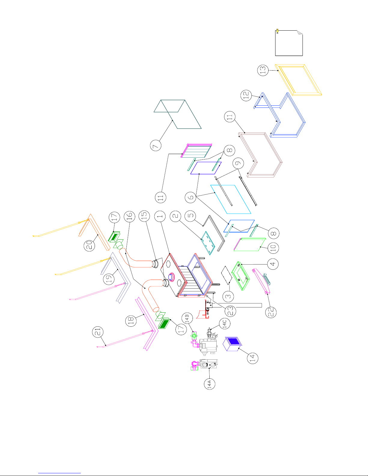
Components of the fire ( See Page 12 diagram 1 )
1 Combustion unit 14 Control box
2 Burner 14A Gas-block manual/remote control
3 Covering plate burner tray 14B G 3/8” internal diameter connection
4 Burner tray 14C Radiator coupling 3/8” external diameter
5 Fender 15 Aluminium collar ø 125
6 Glazing set Panorama version 16 Flexible tube ø 125
7 Glass pane Corner version L/R 17 Outlet grille
8 Glass beading sides 18 Mantle iron Corner version left
9 Glass beading front 19 Mantle iron Corner version right
10 Side panel Corner version L/R 20 Mantle iron Panorama version
11 Front Corner version L/R 21 Support iron
12 Front Panorama version 22 Ventilator set (optional)
13. Front Front version 23 Adjustable legs
Installing the Apertura (See Page 12 diagram 1)
NB: You are recommended to read Section 5 “Concentric duct system” on page 8 before installing the ap-
pliance (in connection with the necessity of fitting the restriction sheet).
· First dismantle Front 11, 12 or 13, depending on the version you have chosen, by removing the 2 or 3-4
socket screws.
· Remove the glazing beads at the same time as the glass panes (6) and (7); Panorama version : first 9
Top/Bottom, then 8 Top/ Left and Bottom/Left then Top/Right and Bottom/Right. Corner version : first 9
Top/Bottom then 8 Top/Bottom Left or Right. Front version : 9 Top/Bottom.
· Take the packed components out of the appliance and check them for damage or breakage.
· Take the appliance off the pallet and lay the appliance on its back.
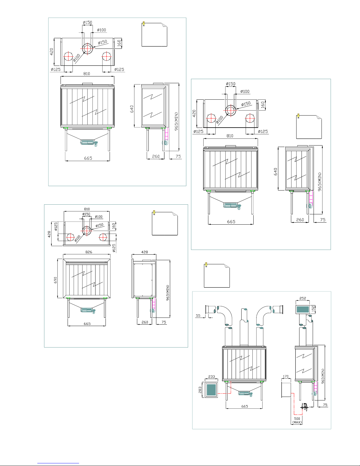
· Fix the adjustable legs (23) to the bottom of the appliance. Saw and adjust the legs to the required height,
taking account of the minimum height given on Page 13 diag. 2, 3 and 4.
· Set the appliance onto the legs and position it in the space where it is to be fitted.
NB: Leave a space ( 3 mm ) around the appliance in order to fit the frame in a later phase, particu larly on the plateau and the sides. Any plasterwork must be taken into account when installing the
Front version. Please also refer to the detailed drawing on Page 17 for the positioning of the mantle
iron.
1= Mantle iron 3= Top plate convection casing
2= Felt 4= Brickwork
Now determine the position and assembly of the convector set and the concentric ducts with accessories.
Refer to Section 5 “Concentric duct system” for this purpose.
· Fit the control box (14) into the space where it is to be built-in.
NB ! The distance between the control box and the appliance depends on the lengths of the wires
mounted from the control box to the pilot light burner.
The maximum length of these is 1000 mm. (Also see Page 13 diag. 5)
Page 8

Page.8
· Connection to the gas main (See Page 12 diag. 1-14B ). Make sure that the regulating equipment does not
become twisted during connection and that no unnecessary tension develops. Ensure the accessibility of
the connecting points for the various components. Check the gas tightness of the connections after they
have been made. Connect the pilot light pipe and the thermocouple [(J) and (K) respectively] to the gas
block (A), taking into account the maximum fixed length of the wires for the thermocouple and spark ca ble. (See Page 14, diag. 6-A). The spark cable (G) still has to be connected to the spark plug of the pilot
light burner.
NB. The spark cable has to be connected to the spark plug in such a way that there is no spark-over to iron
parts anywhere else than on the pilot light burner. Connect the flexible gas pipe to the radiator coupling in
the control box. ( See Page 12 diag. 1-14C) and then to the ø 8 mm copper pipe on the bottom of the appli ance beside the burner tray ( See Page 12 diag. 1-4) with the compression coupling already fitted. Ensure
that the gas pipe is free of dirt and sand.
· Fit the restriction sheet. ( See Page 14 diag. 7 )
NB. The fitting of a restriction sheet depends on the duct situation and so you should first read Section 5
“Concentric duct system” on Page 8.
· Mixing the incandescent granules and incandescent material ( See Page 15 ). Open both bags and put their
contents into the A4 grip-seal bag (containing these instructions ). Shake to mix thoroughly. Scatter the
entire contents over the burner (2) and the bottom of the combustion chamber, distributing it equally over
the surfaces. Ensure that the injection units of the burner are free of incandescent material.
( See Page 15-A )
· Position the log set as shown on Page 15. Do this with care, since soot may be formed if the log set is
wrongly positioned.
· You finally position and fit the glass, the glazing beads and the front in the reverse order as to how you
dismantled them.
Details of gas block rc/mc [remote/manual control] ( see Page 14 diag. 6 )
A. Gas regulator block J. Pilot light pipe
A1. Ignition knob pilot light K. Thermocouple connection
A2. Manual control gas fire L. Burner pressure nipple
B. Hand transmitter remote control M. Pre-pressure nipple
C. Servo motor N. Adjusting screw burner (low setting)
D. Connectors servo motor current O. Adjusting screw burner pressure (high setting)
E. Supply cable servo motor. P. Micro switch connectors
F. Battery holder/ signal receiver
F1. Signal receiver LED
G. Ignition wire
H. Gas supply
I. Gas outlet
5.0 Concentric duct system
The concentric duct system consists of an inner duct of 100 mm in diameter and an outer duct of 150 mm in
diameter. These ducts are concentrically arranged. The combustion gases are extracted via the inner duct,
while fresh air for combustion flows in via the space between the inner and outer ducts. The concentric duct
system enables various connections.
Through the roof and through the external wall.
The route for this system can be laid out in various ways, but there are several important conditions.
· The total permitted vertical duct length is a maximum of 12 metres (the sum of the duct length and the ef-
fective lengths of the bends).
· The horizontal duct length for a roof outlet must not exceed 5 metres, measured between bends, unless
otherwise stated.
· 90° bends have an effective length of 2 metres.
· 45° bends have an effective length of 1 metre.
· The outlet can be placed at any arbitrary position on the roof surface or external wall (inlet and outlet in
identical pressure areas) but must satisfy current regulations.
Page 9

Page.9
The concentric duct system consists of the following components: ( see page 19 )
A. Concentric pipe. K. Flat roof flashing aluminium
B. Concentric 45° bend. L. Storm collar / rosette
C. Wall bracket. M. Horizontal terminal eccentric
D. Not available N. Lead slope roof flashing 20°- 45°
E. Concentric 90° bend. O. Vertical terminal
F. Wall band adjustable. P. Slope roof flashing 5°- 30°
G. Adjustable length.
H. Flat roof plate.
I. Locking band
J. Adjustable roof plate
Connection options for concentric duct system
· Indirect wall feed-through (See Page 14 Diag. 8 & 9 ).
Always place a length of X=1 metre vertically onto the appliance, immediately followed by a 90° bend and
an external horizontal terminal set of Y (min.) length. If required, the horizontal section can be extended to
2 metres plus horizontal terminal (Y max.). See diag. 9.
· Roof feed-through without slope ( see Page 16 diag. 10 ).
A direct route without slopes is possible, up to a maximum length of X=12 metres (excluding vertical ter minal), measured from the connection to the fire. The minimum length is 2 metres. The outlet may occupy
any position on the roof surface (either flat or sloping); the flue and combustion air inlet are located in the
same pressure area. A restriction sheet iron ( See Page 14 diag. 7 ) must be fitted for lengths of 3 metres
and longer for all types of gas.
· Roof feed-through with 45° slope ( see Page 16 diag. 11 ).
Always fit a length of X=1 metre vertically onto the appliance. After this, the route can be continued with
two 45° bends (effective length per bend, 1 metre), until the maximum pipe length of 12 metres is reached
(including bends, but excluding vertical terminal). The minimum length is 3 metres. The outlet may oc cupy any position on the roof surface (either flat or sloping); the flue and combustion air inlet are located
in the same pressure area. A restriction sheet iron ( See Page 14 diag. 7 ) must be fitted for lengths of 3
metres and longer for all types of gas.
· Roof feed-through with 90° slope ( see Page 16 fig. 12 ).
Always fit a length of X=1 metre vertically onto the appliance. After this, the route can be continued with
two 90° bends (effective length per bend, 2 metres), until the maximum pipe length of 12 metres is
reached (including bends, but excluding vertical terminal). The minimum length is 5 metres. The outlet
may occupy any position on the roof surface (either flat or sloping); the flue and combustion air inlet are
located in the same pressure area. Take account of the fact that the horizontal section of pipe must not ex ceed Y=2 metres (measured between bends) and also ensure there is sufficient slope. A restriction sheet
iron ( See Page 14 diag. 7 ) must be fitted for lengths of 3 metres and longer for all types of gas.
Structure of concentric duct system
Installation of indirect horizontal feed-through
· The outlet can also be constructed in the outer wall in a situation with upwards discharge (always 1 metre
vertical first). Possible nuisance to the neighbourhood must be taken into account. The Buildings Decree
contains the relevant regulations. In addition, ensure that the wind pressure on the outlet is not excessive
(e.g. in extremely narrow alleyways), since this can affect the performance of the fire.
Page 10

Page.10
· Create an opening of 155 mm. in diameter in the outer wall (in a flammable external wall, provide for 50
mm. extra space all round the outer pipe) and mount the horizontal terminal with the wall plate on the in side of the wall. On the outside, the wall plate of the horizontal terminal must be sealed sufficiently to the
wall to prevent the possibility of damp and/or flue gases entering the living space.
· If necessary, the duct can be enclosed in a pipe. Adequate fire resistant measures must also be taken if the
duct is to be mounted against flammable materials.
· Determine the position of the fire and the outlet and start construction of the duct with the connection to
the fire. Note the direction of mounting (black sealing rings facing upward), and connect the elements to gether by means of the locking bands.
· Fit a 90° bend directly to the horizontal terminal and make the connection with the elements on the appli ance. Ensure that all connections are fully gastight.
· A fitted sleeve can be used between bends or for the connection to the fire. Use wall brackets to support
the duct, if necessary.
Installation of the vertical terminal
· The outlet can be placed at any arbitrary position on the roof surface (inlet and outlet in identical pressure
areas) but must comply with the current regulations.
· Use a flat roof panel for flat roofs, or a lead roof panel for sloping tiled roofs to ensure a watertight feed through. This can be sloped with the aid of various bends, if necessary.
The opening in the roof decking must be 5 cm. larger all round to ensure sufficient fire resistance. Adjust able roof plates can also be used against the roof decking.
· The regulations in the Buildings Decree state that NEN 6068 (determination of the resistance to fire pene tration between rooms) must be taken into account. An enclosing pipe of fireproof material (e.g. 12 mm.
Promatect fire resistant sheet) must be used as from a distance of 25 mm. from the outer duct.
· Determine the position of the fire and the outlet and start the construction of the duct with the connection
to the fire (always 1 metre vertical first). Note the direction of mounting (black sealing rings facing up ward), and connect the elements together by means of the locking bands. Ensure that all connections are
completely gastight.
· A fitted sleeve can be used between bends or for the connection to the fire. Use 2 wall brackets on each
storey to support the duct.
Page 11

Page.11
6. Gas specifications Apertura
( Nom. capacity depends on the duct situation installed.)
Category
I2L I2H I2E+ I2E+ 12E I2H
Country
NL SP FR BE DE GB
Pre-Pressure MBAR
25 20 20 20 20 20
Burner Pressure MBAR
17,5 14 14 14 14 14
Injection Bore MM
3 2,8 2,8 2,8 2,8 2,8
Smallest Bore MM
Pilot Light CODE
51 51 51 51 51 51
Min. Pressure MBAR
5,4 4 4 4 4 4
Min. Load KW
9,9 10,8 10,8 10,8 10,8 10,8
Max. Load KW
11 12 12 12 12 12
Consumption M³/h
1.226 1.128 1128 1128 1128 1128
Flue Gas Temp. C°
484 471 471 471 471 471
Efficiency Min. %
79,7 82,3 82,3 82,3 82,3 82,3
Efficiency Max. %
71.8 74,2 74,2 74,2 74,2 74,2
Capacity Kw
7,9 8,9 8,9 8,9 8,9 8,9
Category
I3p/b I3p/b I3p/b I3p/b I3p/b I3p/b
Country
NL SP FR BE DE GB
Pre-Pressure MBAR
50/30 37/30 37/30 37/30 50/50 37/30
Burner Pressure MBAR
36/29,4 36/29,4 36/29,4 36/29,4 36/29,4 36/29,4
Injection Bore MM
1,3 1,3 1,3 1,3 1,3 1,3
Smallest Bore MM
Pilot Light CODE
30 30 30 30 30 30
Min. Pressure MBAR
11,2/7,0 11,2/7,0 11,2/7,0 11,2/7,0 11,2/7,0 11,2/7,0
Min. Load KW
6,6/6,84 6,6/6,84 6,6/6,84 6,6/6,84 6,6/6,84 6,6/6,84
Max. Load KW
7,3/7,6 7,3/7,6 7,3/7,6 7,3/7,6 7,3/7,6 7,3/7,6
Consumption M³/h
0.268/0,214 0.268/0,214 0.268/0,214 0.268/0,214 0.268/0,214 0.268/0,214
Flue Gas Temp. C°
341/370 341/370 341/370 341/370 341/370 341/370
Efficiency Min. %
69,5/69,4 69,5/69,4 69,5/69,4 69,5/69,4 69,5/69,4 69,5/69,4
Efficiency Max. %
62,5/62,5 62,5/62,5 62,5/62,5 62,5/62,5 62,5/62,5 62,5/62,5
Capacity kw
4,6/4,7 4,6/4,7 4,6/4,7 4,6/4,7 4,6/4,7 4,6/4,7
Page 12
Page.12
1
Page 13
Page.13
5
2
4
3
Page 14

Page.14
G25
G20/30/31
7
49(G25)
55
(G20/30/31)
6
Page 15

Page.15
A
Page 16

Page.16
8
9
10
11
12
Page 17

Page.17
Page 18

Page.18
A
E
B C
F
I
H G
K
L
J
M N
O P
Page 19

Page.19
CC FLUE SYSTEM PIECE CODE NUMBERS
DESCRIPTION MEASURE
( mm )
CODE NR.
STAINLES STEEL
* ALUMINIUM
** LEAD
CODE NR BLACK PAINTED
A) CONCENTRIC PIPE 1000
500
250
12965000
12965002
12965004
12965500
12965502
12965504
B) CONCENTRIC BEND 45° SET 12965012 12965512
C) WALL BRACKET 12965024 12965524
D) NOT AVAILABLE
E) CONCENTRIC BEND 90° 12965014 12965514
F) WALL BAND ADJUSTABLE 12965026
G) ADJUSTABLE LENGHT 250 12965006
H) FLAT ROOF PLATE 12965020 12965520
I) LOCKING BAND 12965030 12965530
J) ADJUSTABLE ROOF PLATES (SET) 12965040
K) FLAT ROOF FLASHING ALUMIN. 12965050 (ALUM)*
L) STORM COLLAR / ROSETTE 12965070
M) HORIZONTAL TERMINAL EXC. 12965042
N) SLOPE ROOF FLASHING 20-45° 12965054 (LEAD)**
O) VERTICAL TERMINAL 12965044
P) SLOOP ROOF FLASHING 5-30° 12965052
Page 20

Page.20
Page 21

Page.21
This section to be kept by the customer This section to be returned by the customer (see reverse)
Important tips for heating with gas-fired or wood-fired stoves and fireplaces.
Prevent discolouration of walls and ceilings!
There are always dust particles in the air in every living space, even if it is regularly vacuumed! These particles are clearly visible in rays of sunlight and they will not bother you as long as the concentration of particles in the air remains low. The indoor
climate can only be described as bad if these particles are floating through the room in larger quantities for any reason whatsoever and, above all, if the air is additionally polluted by soot and tar particles caused by the burning of candles or oil lamps for
example, and by smoking cigarettes or cigars! In a heated living space, cooled air slowly streams across the floor to the combustion appliance. This air is heated in the convection system of the stove or fire, causing a fast-rising column of warm air to develop, which then spreads throughout the room again. As a consequence, this air always contains dust and other pollutant particles that will leave deposits on cold and often damp surfaces. This is potentially a particular problem in new buildings that are
not yet dry (construction moisture). An unwelcome result of this phenomenon could be discolouration of walls and/or ceilings!
How can you prevent these problems?
If the gas-fired or wood-fired appliance is fitted with insulated covering, one of the following materials should only be used:
Loose white insulation wool (heat resistant to 1000°C)
Rocktherm 180.012 insulation wool (700°C) from Rockwool, or the equivalent
Other mineral insulation wool without binding agents (synthetic resins) or water-repellent substances (mineral oils).
Wait at least 6 weeks before firing a newly-bricked chimney or after renovations, since the construction moisture must have disappeared completely from walls, floor and ceiling. The room where the appliance is located must be well-ventilated and the required ventilation must be in compliance with the stipulations of the local Buildings Decree. Use candles and oil lamps as little
as possible and keep the wicks as short as possible. These two “atmospherics” provide considerable quantities of pollutant and
unhealthy soot particles in your home. Smoke from cigarettes and cigars contains tarry substances which will also leave deposits
on colder and damp walls when heated. If the interior climate is bad, this phenomenon may also occur above radiators and lighting fixtures and at ventilation grilles, although to a lesser degree.
GUARANTEE CERTIFICATE
REGISTRATION CARD
Type of fireplace/heating appliance
Model
Serial number
Design
Name of customer
Street
Postcode, town/city
Telephone
Date of purchase
Name of supplier/installer
Street
Postcode, town/city
Signature and stamp Supplier/Installer
Type of fireplace/heating appliance
Model
Serial number
Design
Name of customer
Street
Postcode, town/city
Telephone
Date of purchase
Name of supplier/installer
Street
Postcode, town/city
Signature and stamp Supplier/Installer
Page 22

Page.22
GUARANTEE CONDITIONS
1. All appliances are supplied under a guarantee against material and manufacturing errors. The guarantee is limited to a maximum of the supply of a replace ment component and only applies if the instructions for installation and use enclosed with the appliance have been followed, and if the product is being
used under normal conditions in the dealer’s assessment.
2. There is a five year guarantee on fire refractory clay, with effect from the date of purchase. Shrinkage cracks and discolouration after heating are not cov ered by the guarantee.
3. There is a five-year guarantee on cast iron fires, cast iron stoves and cast iron recessed fires. A two-year guarantee is given on components of these appli ances, such as ceramic sealants, nuts, bolts, screws, washers, mastic, knob springs, bearings, fans, fireguards and sheet metal parts.
4. There is a two-year guarantee on gas appliances, with the exception of thermocouples and fuses. The appliance must have been installed by a registered
installer in compliance with current standards.
5. The guarantee conditions only apply if the attached guarantee card is completely filled in on the date of purchase and returned to the importer within 10 d
ays. This is also the date of inception of the guarantee.
6. The guarantee lapses if changes have been made to the appliance without the advance knowledge and written permission of the dealer/importer, and when
an appliance has been shipped without sound packaging and transport protection.
7. The following are not covered by the guarantee:
- Defects caused by inexpert assembly and/or treatment.
- Costs of transport, assembly and dismantling.
- Glazing, fire gratings, refractory stones, flue gas baffle plates, heat shields and controllers.
- Paint discolouration which may develop after heating.
- Overheated parts due to faulty installation and/or fitting.
8. In view of the tremendous variations in the possible options for building a chimney, we are unable to give any guarantee regarding the draught of a chim ney that might lead to complaints about smoke. The chimney must be built by a professional and this establishes the guarantee for the proper functioning
of this appliance.
9. The dealer/importer will supply a new component free of charge for every component that becomes defective during the guarantee period. The dealer must
return the defective component to the importer, stating date of purchase, type of appliance and serial number.
10. Renewal or replacement of components that fall under the guarantee cannot prolong th e total length of the guarantee. The guarantee provides no right
whatsoever to indemnification in the event it is not possible to use the fire.
11. Liability can never be accepted for loss in any form whatsoever sustained by the customer, third parties or their property and caused directly or indirectly
by the product.
12. Complaints will only be dealt with if the customer has met all his obligations, including his obligation to pay.
13. For further provisions, please refer to our Metaalunie and Orgalime conditions, which are filed at the office of the Court in Rotterdam (the Netherlands).
Send the guarantee card to your dealer / importer in
a properly stamped envelope
Address;
Postcode ;
Town/city ;
G U A R A N T E E C A R D
 Loading...