

USER MANUAL
VTB 3000 - 9000
150000 - 18000
2 40.020.939 - rev. 04 - 2011 VTB 3000/9000/15000
Nederlands
A
Nederlands /i
Nederlands .......................................... 4
THERMOBILE
B
C
D
E
F
G
H
I
MODEL
VOLTS
INPUT
CURRENT
FREQUENCY
PROTECTION
PROD. NR:
Fabr.year 2007
THERMOBILE Ind. B.V. Breda, Holland
- 1 - - 2 -
E
- 3 -
D
VTB 9000
400 V 3~
9 kW
13 A
50 Hz
IP 44
40.107.035
Serial nr: XXX
B
C
F
B
English................................................11
Deutsch.............................................. 18
Français............................................. 26
A
G
A
Español.............................................. 35
Русский язык .............................................43
A B C D
F
E
kW kW
- 4 - - 5 -
2 40.020.939 - rev. 06 - 2016
A
B
C
D
VTB
VTB
40.020.939 - rev. 06 - 2016
3

Nederlands
All
Nederlands
Nederlands
Inhoud
Veiligheidsinstructies ...................................5
Introductie....................................................6
Voorbereidingen...........................................7
Gebruik ........................................................7
Onderhoud...................................................8
Storingen......................................................8
Reserveonderdelen ...................................10
Technische informatie ................................10
Installatie van accessoires.........................10
EG-Verklaring van overeenstemming........10
Voorwoord
Deze handleiding bevat de
gebruiksaanwijzing voor de op de kaft
vermelde kachel. De informatie in deze
handleiding is belangrijk voor een juist en
veilig gebruik van de kachel.
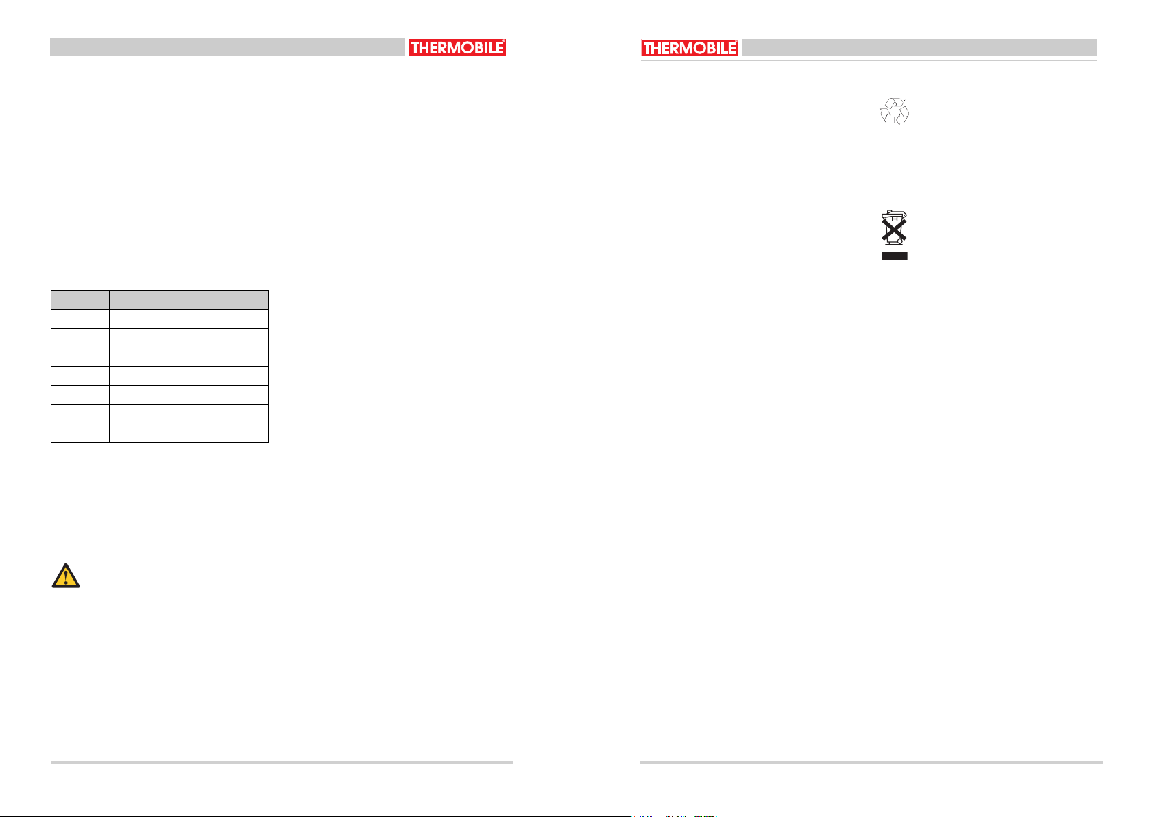
Identificatie van het product (Fig. 1 & 2)
Het identificatieplaatje is bevestigd zoals
aangegeven in fig. 2. Het identificatieplaatje
bevat de volgende gegevens:
A Model
B Voltage
C Input
D Stroom
E Frequentie
F Beschermingsgraad tegen stof en vocht
G Productiecode
H Jaar van fabricage
I Serienummer
Service en technische ondersteuning
Neem voor informatie over de kachel contact
op met uw dealer of met de fabrikant.
Zorg dat u de volgende gegevens bij de hand
hebt: type en serienummer van de kachel.
Garantie en aansprakelijkheid
Voor garantie en aansprakelijkheid, zie de
algemene garantiebepalingen.
Milieu
Let op
De kachel is gemaakt van diverse
metalen en kunststoffen. De kachel
bevat tevens elektronische
onderdelen, die als elektronisch afval
moeten worden behandeld. Neem
contact op met uw dealer voor
nadere informatie.
een van toepassing in de
Europese Unie
Afvalverwijdering van elektrische
& elektronische apparatuur voor
zakelijk gebruik.
Voor nadere informatie aangaande
het wegwerpen van producten voor
zakelijke doeleinden aan het einde
van hun levensduur, wordt u verzocht
contact op te nemen met uw dealer
of distributeur in uw land. Dit product
mag niet samen met of in de vorm
van commercieel afval worden
weggegooid.
1 VEILIGHEIDSINSTRUCTIES
1.1 Pictogrammen in deze handleiding
VOORZICHTIG
Wijst op gevaar voor beschadiging
van de apparatuur.
WAARSCHUWING
Wijst op een gevaarlijke situatie, die
de dood of ernstige verwondingen tot
gevolg kan hebben.
WAARSCHUWING
Schakel bij onderhouds- of
reparatiewerkzaamheden aan de
heteluchtkachel altijd de elektrische
stroom uit!
Heet
Sommige vlakken kunnen heet zijn!
Wacht met onderhoud totdat deze
onderdelen voldoende zijn afgekoeld.
Suggesties en tips om de uitvoering
van de betreffende taken of
handelingen te vereenvoudigen.
1.2 Pictogrammen op de kachel
A Identificatieplaatje.
1.3 Gebruik dit product waarvoor het
bestemd is
De in deze handleiding beschreven kachels
zijn ontworpen voor de verwarming van
bouwwerken en -keten. Tevens kunt u de
kachel gebruiken voor het bespoedigen van
droogprocessen.
1.4 Algemene instructies
WAARSCHUWING
• Lees deze handleiding
zorgvuldig door, alvorens de
kachel te gebruiken.
• Bewaar dit document bij de
kachel.
• Volg de beschreven procedures.
• Sluit de kachel alleen aan op een
goed geaard stopcontact dat
voldoet aan de in het land
geldende normen. Raadpleeg bij
twijfel een deskundige.
• Zorg bij gebruik van een
verlengkabel dat deze zwaar
genoeg is voor de kachel.
• Rol een kabelhaspel volledig uit.
• Dek de kachel niet af. Laat de
lucht IN- en UITLAAT vrij.
• Steek geen voorwerpen in de
kachel.
• Plaats geen brandbare
voorwerpen voor de kachel, houd
voldoende afstand.
• Gebruik de kachel niet in
explosiegevaarlijke ruimtes of in
ruimtes met agressieve gassen
zoals ammoniak, lijm, verfverdunners.
• Voer uitsluitend reparatie- en
onderhoudswerkzaamheden uit
als de kachel voldoende is
afgekoeld, en nadat de steker uit
de contactdoos is verwijderd.
• Reinig de binnenkant van de
kachel nooit met water, maar
gebruik perslucht.
• Maak bij zichtbare gebreken de
kachel direct spanningsloos en
laat de kachel repareren door
een deskundige.
• Houd steeds rekening met de
geldende veiligheidsvoorschriften ter preventie van
gevaar en ongevallen.
4 40.020.939 - rev. 06 - 2016
VTB
VTB
40.020.939 - rev. 06 - 2016
5
Nederlands
2 INTRODUCTIE
Nederlands
2.1 Doel
Deze elektrische kachels hebben een radiaal
ventilator en zijn gemaakt voor horizontale
binnenopstelling.
2.2 Werkingsprincipe
De VTB kachels zijn
dubbelwandig uitgevoerd. Ze zijn opgebouwd
uit een verzinkt plaatstalen binnenframe en
een buitenomkasting. In het binnenframe zijn
een of meerdere verwarmingselementen
gemonteerd. Een radiaalventilator blaast de
lucht over de verwarmingselementen.
Bij oververhitting schakelt de kachel uit.
Oververhitting ontstaat als de luchtstroom te
laag is (te lange slang), of als het
binnenframe aan de binnenzijde vervuild is.
Na het afkoelen schakelt de kachel vanzelf
weer in (automatische reset).
Zorg daarna voor een betere luchtstroom.
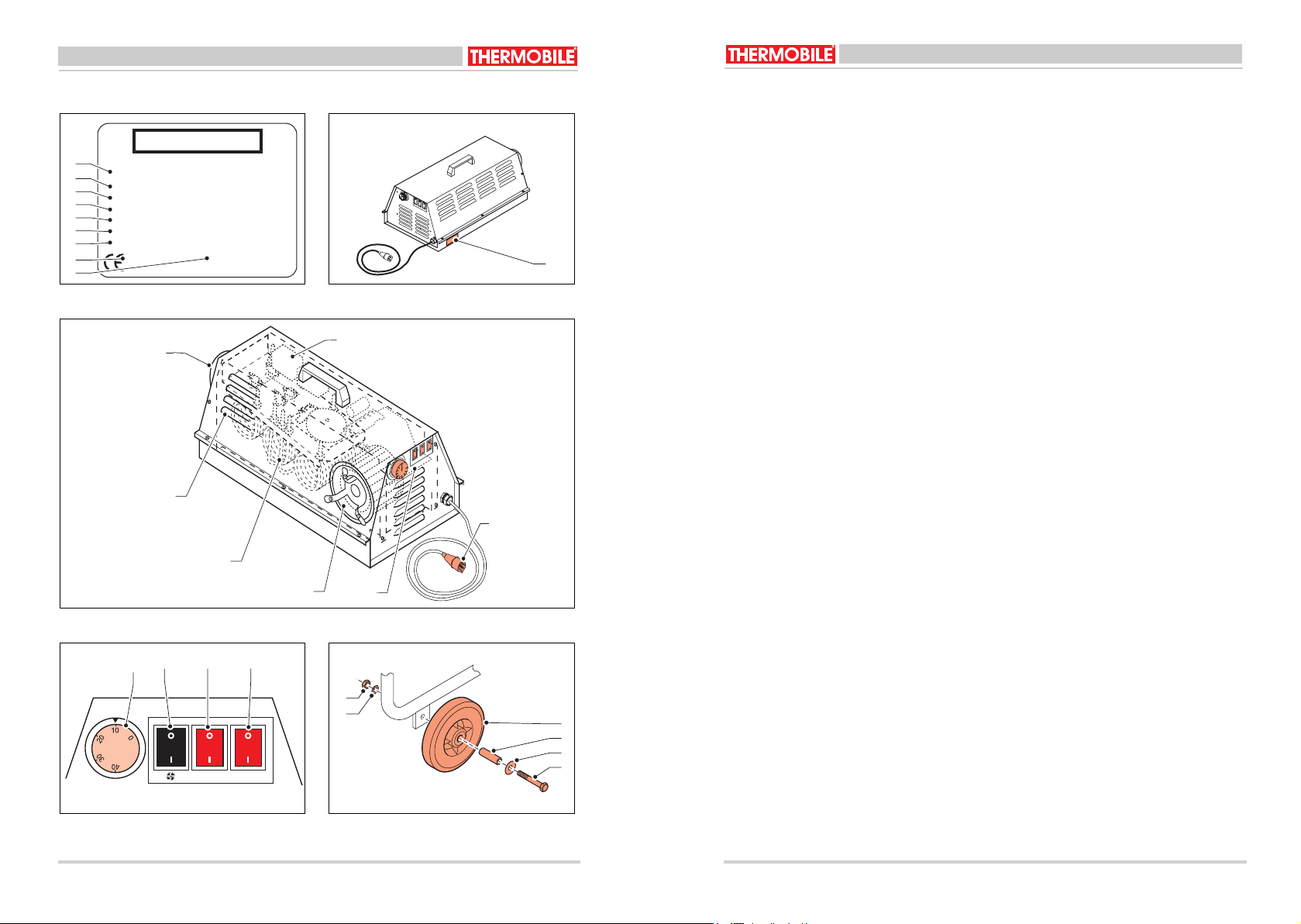
2.3 Hoofdcomponenten (Fig. 3)
A Bedieningspaneel
B Verwarmingselementen
C Ventilator
D Luchtinlaatsleuven
E Luchtuitlaat
F Relais
G Netaansluiting
2.4 Maximaalthermostaat
De kachel heeft een of twee ingebouwde
maximaalthermostaten die de kachel
uitschakelen als de maximaal toelaatbare
temperatuur van de warme lucht wordt
overschreden.
2.5 Regelthermostaat
De kachel heeft een regelthermostaat die de
kachel uitschakelt als de ingestelde
maximale omgevingstemperatuur wordt
bereikt.
2.6 Bedieningspaneel (Fig. 4)
De kachel heeft een regelthermostaat (A) en
& (C)
2 of 3 tuimelschakelaars (B)
ventileren en verwarmen. De VTB 3000 heeft
& (D) voor
slechts 1 schakelaar voor verwarmen. VTB
9000 en VTB 15000/18000 hebben er twee.
A Regelthermostaat
- 2 - 38 °C
B Schakelaar ventileren
- 0 = Ventilator uit
1 = Ventilator aan
C Schakelaar verwarmen
- 0 = Verwarming uit
1 = Verwarming aan
D Tweede schakelaar verwarmen
- 0 = Extra verwarming uit
1 = Extra verwarming aan
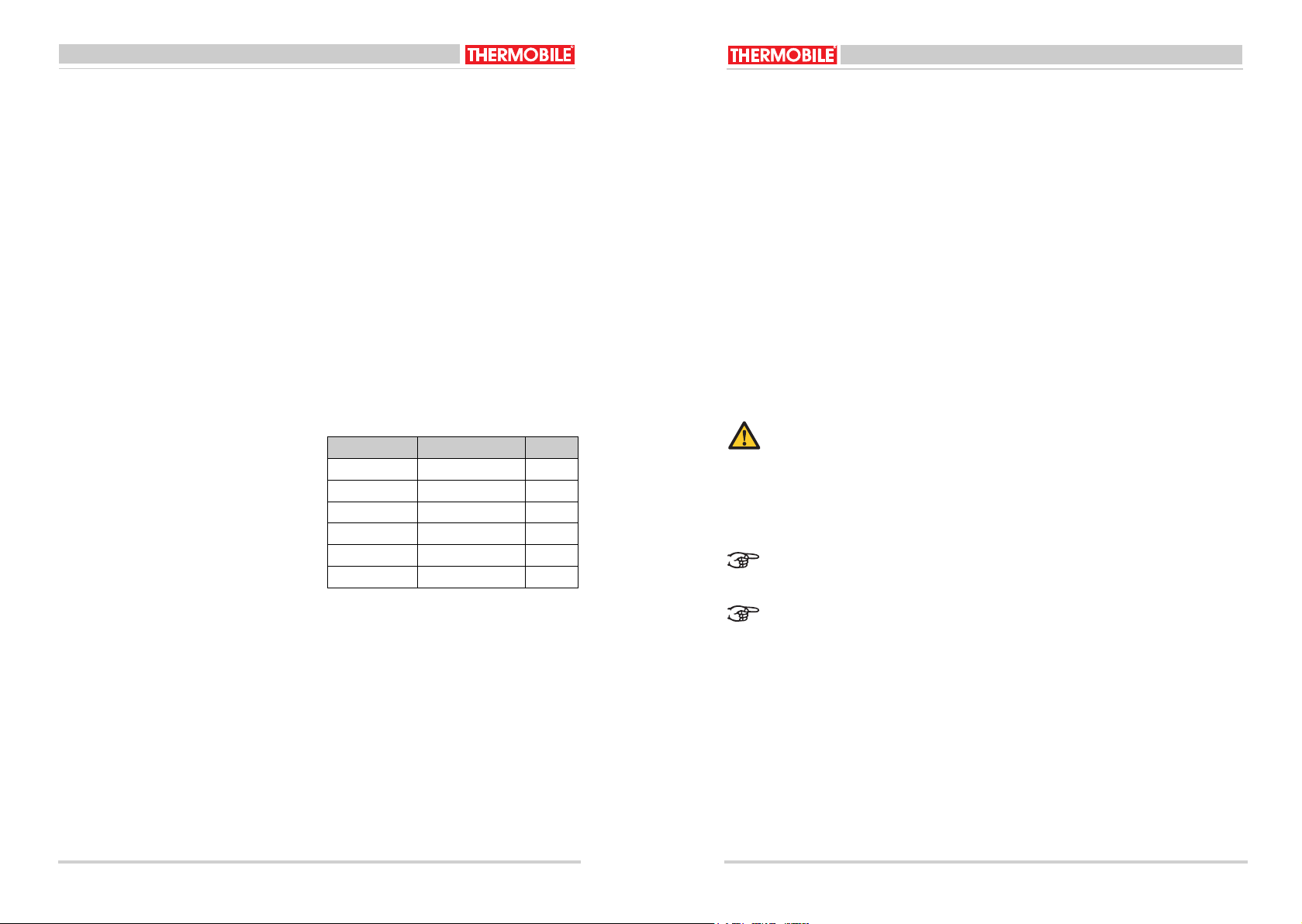
2.7 Tabel voor verwarmingsvermogen
/i
Type kachel Schakelaar (aan) kW
VTB3000 C 3
VTB9000 C 4,5
C+D 9
VTB15000/ C
18000
6/9
9/9D
C+D 15/18
2.8 Optionele Accessoires
• Slang voor warmtetransport naar moeilijk
bereikbare plaatsen.
3 VOORBEREIDINGEN
3.1 Verpakking verwijderen
1. Verwijder de verpakking van de kachel.
2. Controleer de inhoud op eventuele
schade.
3. Lees de gebruiksaanwijzing.
3.2 Wielen monteren aan VTB 15000/
18000 (Fig. 5)
Monteer de wielen volgens de tekening.
A Wiel
B Bus
C Ring M10
D Bout M10 x 70
E Veerring M10
F Moer M10
3.3 Installatie
1. Controleer of de kachel op de juiste
spanning / frequentie wordt aangesloten.
WAARSCHUWING
Kachel niet aansluiten indien de
spanning / frequentie afwijkt van de
waarden zoals vermeld op de
typeplaat.
2. Zorg voor een stabiele opstelling van de
kachel.
Plaats de kachel altijd horizontaal
met de voetdoppen / wielen onder.
Het wisselen van fasedraden in de
steker heeft geen invloed op de
werking van de 3-fasen kachel en op
de draairichting van de ventilator.
De NUL pen van de 5-polige steker
niet gebruiken.
4 GEBRUIK
4.1 Inschakelen
• Ventileren:
zet alleen de keuzeschakelaar voor
ventileren op 1.
De thermostaat treedt niet in werking.
• Verwarmen:
zet alleen de gewenste schakelaar(s)
voor verwarmen op 1.
Stel de thermostaat in voor de gewenste
omgevingstemperatuur.
• Verwarmen en continu ventileren:
- Zet de schakelaar voor ventileren op
1.
- Zet de gewenste schakelaar(s) voor
verwarmen op 1.
- Nadat de thermostaat de verwarming
heeft uitgeschakeld blijft de ventilator
draaien.
4.2 Uitschakelen
VTB 3000:
1. Zorg dat de ventilator draait.
2. Zet de schakelaar voor verwarmen op 0.
3. Wacht tot er geen warme lucht meer uit
de luchtuitlaat komt.
4. Zet de schakelaar voor ventileren op 0.
VTB 9000 en 15000/18000:
1. Zet alle schakelaars op 0.
2. Laat de steker nog 5 minuten in de
contactdoos om automatisch na te
koelen.
6 40.020.939 - rev. 06 - 2016
VTB
VTB
40.020.939 - rev. 06 - 2016
7
Nederlands
5 ONDERHOUD
Nederlands
/i
5.1 Onderhoudstabel
Registreer na elk winterseizoen het
onderhoud in de tabel achterin dit boek.
Beschrijving Periode
Iedere
week
Iedere
maand
Verwijder stof en aanslag van de kachel. X
Controleer de kachel (in een schone omgeving).
Controleer de kachel (in een stoffige omgeving).
Controleer en reinig het inlaatrooster. X
Controleer de ventilator op juiste werking,
X
vuil en beschadigingen.
Controleer de bedrading van de kachel. X
Heet
6 STORINGEN
Raak de uitlaat en het binnenframe
niet aan!
Wacht met het onderhoud totdat
deze zijn afgekoeld.
5.2 Algemeen
WAARSCHUWING
Neem de netspanningssteker uit de
Zorg dat de netspanning
ingeschakeld is tijdens het
storingzoeken.
WAARSCHUWING
Neem de netspanningssteker uit de
contactdoos tijdens een reparatie.
contactdoos tijdens het onderhoud.
Als de kachel voor langere tijd opgeslagen
wordt:
1. Schakel de kachel uit.
2. Neem de netspanningssteker uit de
contactdoos.
3. Reinig de kachel.
Ieder half
jaar
Dealer
Ieder jaar
Dealer
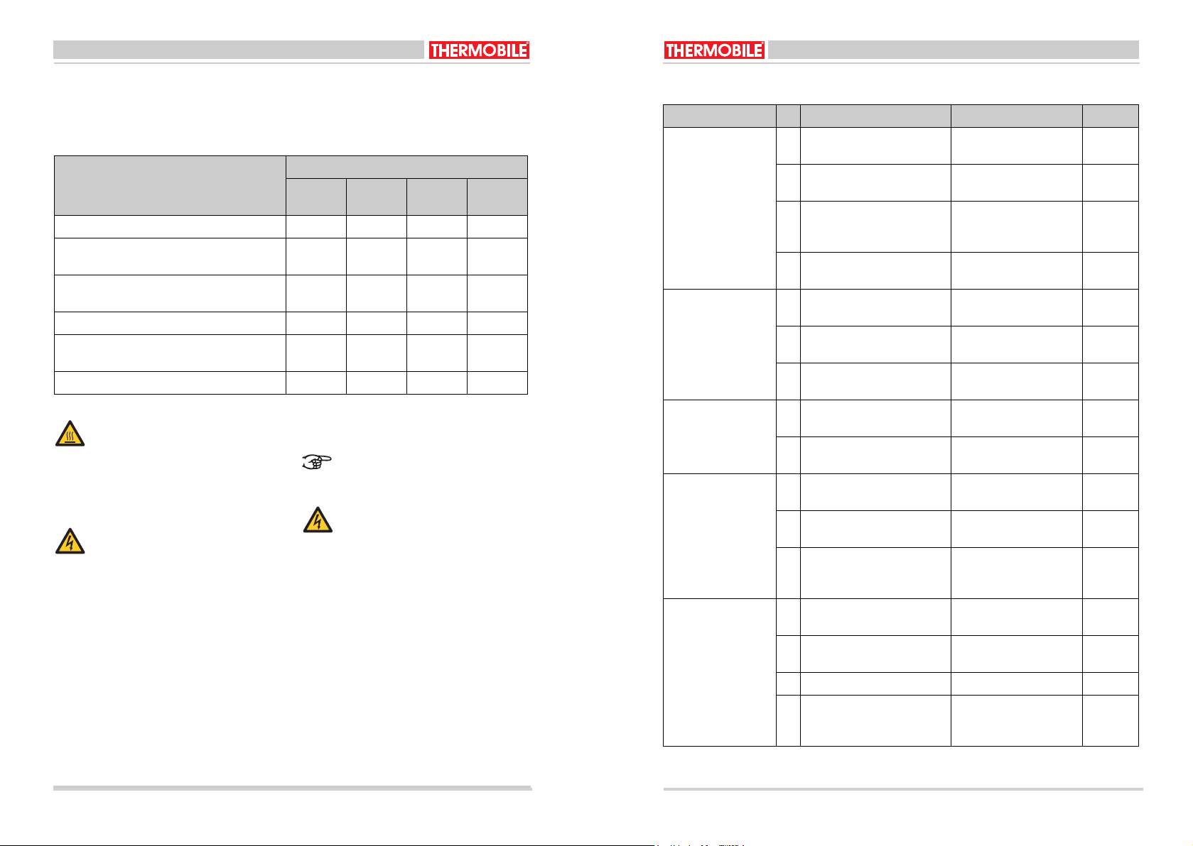
6.1 Tabel storingzoeken
/i
Storing Oorzaak Oplossing Actie
De kachel werkt niet. 1 De kachel heeft geen span-
ning.
2 Defect in het bedieningspa-
neel.
3 Fase - NUL draden verwis-
Controleer de elektrische
Gebruiker
aansluiting.
Repareer of vervang het
Dealer
bedieningspaneel.
Herstel de verbinding. Gebruiker
seld in een 5-polige steker /
contrasteker.
4 Interne zekering (2A) defect.
Vervang de zekering. Dealer
(VTB 9000/15000/18000)
Ventilator draait niet,
geen warmte.
5 De thermostaat is ingesteld
Corrigeer de instelling. Gebruiker
op een te lage temperatuur.
6 Zekering defect in uw instal-
latie.
Vervang de zekering.
(Draai deze goed vast).
7 Ventilatormotor stuk. Vervang de ventilatormo-
Gebruiker
Dealer
tor.
Ventilator draait niet,
kachel wordt wel
warm.
8 Zekering defect in uw instal-
latie.
Vervang de zekering.
(Draai deze goed vast).
9 Ventilator defect. Vervang de ventilatormo-
Gebruiker
Dealer
tor.
Ventilator draait wel
maar de kachel geeft
geen warmte.
10 Spanning te laag Controleer de elektrische
aansluitingen.
11 Eén zekering defect in uw
installatie.
12 Kabel of verlengkabel
defect. Kachel werkt op 2
Vervang de zekering.
(Draai deze goed vast).
Herstel de verbinding of
de installatie.
Dealer
Gebruiker
Gebruiker
fasen.
Ventilator draait normaal, weinig warmte
50%.
13 Eén zekering defect in uw
installatie.
14 Kabel of verlengkabel
Vervang de zekering.
Gebruiker
(Draai deze goed vast).
Herstel de verbinding. Gebruiker
defect.
15 Kachel werkt op 2 fasen. Herstel de verbinding. Gebruiker
16 Eén losse of verbrande
raad in de steker / contra-
d
Herstel de verbinding. Gebruiker
steker of verlengkabel.
8 40.020.939 - rev. 04 - 2011 VTB 3000/9000/15000
8 40.020.939 - rev. 06 - 2016
VTB
VTB
40.020.939 - rev. 06 - 2016
9
Nederlands
English
Onl
Noteer de onderhoudsgegevens in tabel A in
de annex achterin dit boek.
7 RESERVEONDERDELEN
Raadpleeg de dealer voor het gebruik van
reserveonderdelen.
8 TECHNISCHE INFORMATIE
• Zie voor de technische specificaties tabel
B in de annex achterin dit boek.
• Zie voor het elektrische schema het
schema C in de annex achterin dit boek.
8.1 Uitleg van het elektrische schema
/i
Pos. Omschrijving
C Condensator
CL Maximaalthermostaat
M Motor
Th Thermostaat
Ac Nakoeling
F Interne zekering
Tr Transformator
9 INSTALLATIE VAN ACCESSOIRES
9.1 Luchtslang
Er kan een luchtslang aan de
uitblaasopening van de kachel worden
gekoppeld, om op grote afstand van de
kachel warme lucht te blazen.
VOORZICHTIG
Controleer de temperatuurweerstand
van de gebruikte slang.
Neem contact op met de dealer voor
informatie over maximumlengtes van
uitblaasslangen, bochten, verdeelstukken en
slangklemmen.
10 EG-VERKLARING VAN
OVEREENSTEMMING
De EG-Verklaring van overeenstemming kunt
u vinden op www.thermobile.nl.
English
Contents
Safety instructions..................................... 12
Introduction ............................................... 13
Preparations.............................................. 14
Use............................................................ 14
Maintenance ............................................. 15
Faults ........................................................ 15
Spare parts................................................ 17
Technical information ................................ 17
Installing accessories................................ 17
EC Declaration of conformity .................... 17
Preface
This manual contains the instructions for use
of the heater shown on the cover. The
information in this manual is important for the
correct and safe use of the heater.
Identification of the product (Figs. 1 & 2)
The identification plate is attached as shown
in fig. 2. The identification plate contains the
following data:
A Model
B Voltage
C Input
D Current
E Frequency
F Protection level against dust and
moisture
G Production code
H Year of manufacture
I Serial number
Service and technical support
Please contact your dealer or the
manufacturer for information about the
heater. Make sure you have the following
data at hand: type and serial number of the
heater.
Warranty and liability
For warranty and liability, see the general
warranty regulations.
Environment
Note
The heater is made of various metals
and synthetic materials. The heater
also contains electronic parts, which
must be treated as electronic waste.
Please contact your dealer for further
information.
y applicable to the European
Union
Waste disposal of electric &
electronic equipment for business
use.
For further information regarding the
disposal of products for business use
at the end of their life span, please
contact your dealer or distributor in
your country. This product may not
be disposed of together with
commercial waste or as commercial
waste.
10 40.020.939 - rev. 06 - 2016
VTB
VTB
40.020.939 - rev. 06 - 2016
11
English
1 SAFETY INSTRUCTIONS
English
1.1 Pictograms in this manual
Caution
Indicates risk of damage to the
appliance.
Warning
Indicates a dangerous situation that
may lead to death or serious injuries.
Warning
Always switch off power when
performing maintenance or repairs on
the convector heater!
Hot
Some surfaces may be hot! Wait until
these parts have sufficiently cooled
down before performing
maintenance.
Suggestions and tips to facilitate the
specified tasks or actions.
1.2 Pictograms on the heater
A Identification plate
1.3 Use this product for its intended
use
The heaters described in this manual have
been designed for heating building sites and
huts. You can also use the heater to speed
up drying processes.
1.4 General instructions
Warning
• Read this manual carefully
before using the heater.
• Keep this document with the
heater.
• Follow the described procedures.
• Only connect the heater to a
socket that has been correctly
earthed that meets the standards
that apply in the relevant country.
Consult an expert if in any doubt.
• Make sure that any extension
cable used has the required
weight for the heater.
• Fully unwind a cable reel.
• Do not cover the heater. Make
sure the air INLET and OUTLET
are not obstructed.
• Do not insert any objects into the
heater.
• Do not place any inflammable
objects in front of the heater and
make sure you keep sufficient
distance.
• Do not use the heater in rooms
where there is an explosion risk
or in rooms where there are
aggressive gases such as
ammonia, glue or paint thinners.
• Only perform repair and
maintenance activities when the
heater has sufficiently cooled
down and after removing the plug
from the socket.
• Never clean the inside of the
heater using water but use
compressed air.
• Make sure you immediately
disconnect the power supply
when there are visible faults or
defects and have the heater
repaired by an expert.
• At all times take into account the
applicable safety regulations with
regard to the prevention of
danger and accidents.
2 INTRODUCTION
2.1 Purpose
These electrical heaters have a radial fan
and are made for horizontal indoor
installation.
2.2 Working principle
The VTB heaters are
double-walled models. They consist of an
electroplated sheet steel inside frame and an
external enclosure. One or more heating
elements are installed in the inside frame. A
radial fan blows the air over the heating
elements.
The heater will switch off when overheated.
Overheating will occur when the air flow is
too low (hose that is too long) or when the
inside frame is dirty on the outside. Once it
has cooled down, the heater will switch on
automatically (automatic reset).
Make sure thereafter that there is better air
flow.
2.3 Main components (Fig. 3)
A Operating panel
B Heating elements
C Fan
D Air inlet slots
E Air outlet
F Relay
G Mains connection
2.4 Maximum thermostat
The heater has one or two inbuilt maximum
thermostats that switch off the heater when
the maximum permissible temperature of the
hot air is exceeded.
2.5 Control thermostat
The heater has a control thermostat that
switches off the heater when the set
maximum ambient temperature is reached.
2.6 Control panel (Fig. 4)
The heater has a control thermostat (A) and 2
or 3 rocker switches (B) & (C) & (D)
for
ventilation and heating. The VTB 3000 only
has 1 switch for heating purposes. VTB 9000
and VTB 15000/18000 have two.
A Control thermostat
- 2 - 38 °C
B Ventilation switch
- 0 = Fan off
1 = Fan on
C Heating switch
- 0 = Heating off
1 = Heating on
D Second heating switch
- 0 = Additional heating off
1 = Additional heating on
2.7 Table for heating power
/i
Type of
Switch (on) kW
heater
VTB3000 C 3
VTB9000 C 4,5
C+D 9
VTB15000/ C
6/9
18000 D 9/9
C+D 15/18
2.8 Optional accessories
• Hose for heat distribution to places that
are difficult to reach.
12 40.020.939 - rev. 06 - 2016
VTB
VTB
40.020.939 - rev. 06 - 2016
13

English
3 PREPARATIONS
English
4 USE
5 MAINTENANCE
/i
3.1 Remove packaging
1. Remove packaging from the heater.
2. Check the contents for any damage.
3. Read the instructions for use.
3.2 Installing the wheels on the VTB
15000/18000 (Fig. 5)
Install the wheels as shown in the drawing.
A Wheel
B Bush
C M10 ring
D M10 x 70 bolt
E M10 lock washer
F M10 nut
3.3 Installation
1. Check whether the heater is connected
to the correct voltage/frequency.
Warning
Do not connect the heater if the
voltage/frequency deviates from the
values as listed on the nameplate.
2. Make sure that the heater has a stable
set-up.
Always position the heater
horizontally with the foot caps/wheels
down.
Exchanging phase wires in the plug
will not influence the operation of the
3-phase heater and the turning
direction of the fan.
Do not use the ZERO pin of the 5pole connector.
4.1 Switching on
• Ventilate: only set the selector switch for
ventilation to 1.
The thermostat will not become active.
• Heat: only set the required switch(es) for
heating to 1.
Set the thermostat for the required
ambient temperature.
• Heating and continuously ventilate:
- Set the switch for ventilating to 1.
- Set the required switch(es) for
heating to 1.
- After the thermostat has switched off
the heating, the fan will keep running.
4.2 Switch off
VTB 3000:
1. Make sure that the fan runs.
2. Set the switch for heating to 0.
3. Wait until no hot air comes out of the air
outlet.
4. Set the switch for ventilating to 0.
VTB 9000 and 15000/18000:
1. Set all switches to 0.
2. Leave the plug in the socket another 5
minutes to make sure it automatically
cools down.
5.1 Maintenance table
Use the table in this manual to record the
maintenance after each winter.
Description Period
Weekly Monthly Every six
Annually
months
Remove dust and deposits from the heater. X
Check the heater (in a clean environment). Dealer
Check the heater (in a dusty environment). Dealer
Check and clean the inlet grid. X
Check the correct operation of the fan and
X
check for dirt and damages.
Check the heater's wiring. X
Hot
6 FAULTS
Do not touch the outlet or the inside
frame!
Do not start maintenance until they
have cooled down.
5.2 General
Warning
Make sure that the mains voltage is
connected during troubleshooting.
Warning
Remove the mains plug from the
socket during repair work.
Remove the mains plug from the
socket during maintenance.
For long-term storage of the heater:
1. Switch off the heater.
2. Remove the mains plug from the socket.
3. Clean the heater.
14 40.020.939 - rev. 06 - 2016
VTB
VTB
40.020.939 - rev. 06 - 2016
15

English
6.1 Troubleshooting table
English
/i
Fault Cause Solution Action
The heater is not
functioning.
1 The heater has no voltage. Check the electrical con-
nection.
2 Defect in the operating
panel.
3 Phase - exchange the ZERO
Repair or replace the
operating panel.
Repair the connection. User
wires in a 5-pole connector/
female connector.
4 Internal fuse (2A) faulty.
Replace the fuse. Dealer
(VTB 9000/15000/18000)
The fan does not turn
and there is no heat.
5 The thermostat is set to a
too low temperature.
6 Fuse is faulty in your sys-
tem.
Correct the settings. User
Replace the fuse. (Make
sure it is tight.)
7 Fan motor is broken. Replace the fan motor. Dealer
The fan does not turn
but the heater does
heat up.
The fan does turn but
the heater does not
emit heat.
8 Fuse is faulty in your sys-
tem.
Replace the fuse. (Make
sure it is tight.)
9 Fan faulty Replace the fan motor. Dealer
10 Voltage too low Check the electrical con-
nections.
11 One fuse is faulty in your
system.
12 Cable of the extension cable
faulty. Heater functions on 2
Replace the fuse. (Make
sure it is tight.)
Repair the connection of
the system.
phases.
The fan turns as normal but there is little
heat, 50%.
13 One fuse is faulty in your
system.
14 Cable of the extension cable
Replace the fuse. (Make
sure it is tight.)
Repair the connection. User
faulty.
15 Heater functions on 2
Repair the connection. User
phases.
One loose or burnt cable in
16
Repair the connection. User
the connector/female connector or extension cable.
User
Dealer
User
User
Dealer
User
User
User
7 SPARE PARTS
Contact the dealer for the use of spare parts.
8 TECHNICAL INFORMATION
• For technical specifications, see table B
in the annex at the back of this manual.
• For the electrical circuit diagram, refer to
diagram C in the annex at the back of this
manual.
8.1 Explanation of the electrical circuit
diagram
/i
Pos. Description
C Condenser
CL Maximum thermostat
M Motor
Th Thermostat
Ac After-cooling
F Internal fuse
Tr Transformer
9 INSTALLING ACCESSORIES
9.1 Air hose
An air hose may be connected to the outlet
opening of the heater in order to blow hot air
at a large distance from the heater.
Caution
Check the temperature resistance of
the hose used.
Contact your dealer for information about the
maximum length of the outlet hoses, bends,
manifolds and hose clamps.
10 EC DECLARATION OF
CONFORMITY
For the EC declaration of conformity, go to
www.thermobile.nl.
Record the maintenance details in table A in the annex at the back of this manual.
16 40.020.939 - rev. 06 - 2016
VTB
VTB
40.020.939 - rev. 06 - 2016
17
Deutsch
Gilt
n
G
e
n
Gilt
Deutsch
Deutsch
Inhalt
Sicherheitshinweise...................................19
Einführung .................................................20
Vorbereitungen ..........................................21
Verwendung...............................................22
Wartung .....................................................23
Störungen ..................................................23
Ersatzteile..................................................25
Technische Informationen..........................25
Installation von Zubehör ............................25
EG-Konformitätserklärung .........................25
Vorwort
Dieses Handbuch enthält die
Bedienungsanleitung für den auf dem
Umschlag aufgeführten Heizer. In dieser
Betriebsanleitung sind wichtige
Informationen in Bezug auf die
ordnungsgemäße und sichere Funktion des
Heizers enthalten.
Typenschild des Produkts (Abb. 1 & 2)
Das Typenschild ist, wie in Abb. 2 dargestellt,
angebracht. Auf dem Typenschild finden Sie
die folgenden Daten:
A Modell
B Spannung
C Input
D Strom
E Frequenz
F Schutzklasse gegen Staub und
Feuchtigkeit
G Herstellungscode
H Herstellungsjahr
I Seriennummer
Kundendienst und technische
Unterstützung
Weitere Informationen zum Heizer hält Ihr
Händler oder Hersteller bereit. Achten Sie
darauf, dass Sie dann folgende Angaben zur
Hand haben: Typ und Seriennummer des
Heizers.
Garantie und Haftung
Die Bestimmungen in Bezug auf die Garantie
und Haftung finden Sie unter den
allgemeinen Garantiebedingungen.
Entsorgung
Hinweis
Der Heizer besteht aus
verschiedenen Metallen und
Kunststoffen. Der Heizer enthält
ferner elektronische Komponenten,
die als elektronischer Abfall zu
entsorgen sind. Weiterführende
Informationen hält Ihr Fachhändler
für Sie bereit.
nur für die Europäische Union
nur für die Europäische Union
Abfallentsorgung von elektrischer
Abfallentsorgung von elektrischer
elektronischer Ausrüstung für den
und elektronischer Ausrüstung für
gewerblichen Gebrauch.
den gewerblichen Gebrauch.
Für weitere Informationen über die E
Für weitere Informationen über die
von Produkten für den gewerblichen
Entsorgung von Produkten für den
Ende ihrer Lebensdauer nehmen Sie
gewerblichen Gebrauch am Ende
mit Ihrem Händler oder Vertrieb in Ihr
ihrer Lebensdauer nehmen Sie bitte
Dieses Produkt darf weder zusamme
Kontakt mit Ihrem Händler oder
als Hausmüll entsorgt werden.
Vertrieb in Ihrem Land auf. Dieses
Produkt darf weder zusammen mit
noch als Hausmüll entsorgt werden.
1 SICHERHEITSHINWEISE
1.1 Piktogramme in dieser
Betriebsanleitung
Vorsicht
Gefahr einer Produktbeschädigung
Achtung
Gefährliche Situationen, die den Tod
oder ernsthafte Verletzungen zur
Folge haben können.
Achtung
Bei Wartungs- oder
Reparaturarbeiten am Heizer immer
die Stromversorgung ausschalten!
Heiß
Einige Flächen können heiß sein!
Warten Sie mit der Ausführung der
Wartungsarbeiten, bis diese Bereiche
abgekühlt sind.
Hinweise und Tipps, um die
Ausführung der betreffenden
Aufgaben oder Handlungen zu
vereinfachen.
1.2 Piktogramme am Heizer
A Typenschild.
1.3 Das Produkt darf nur gemäß
seinem bestimmungsgemäßen
Verwendungszweck betrieben
werden.
Die in dieser Anleitung beschriebenen Heizer
sind auf das Beheizen von Gebäuden und
Baubaracken ausgelegt. Außerdem können
Sie den Heizer zum Beschleunigen von
Trocknungsprozessen verwenden.
1.4 Allgemeine Anweisungen
Achtung
• Lesen Sie zunächst dieses
Handbuch aufmerksam durch,
bevor Sie den Heizer zum
Einsatz bringen.
• Bewahren Sie dieses Dokument
in unmittelbarer Nähe des
Heizers auf.
• Befolgen Sie die beschriebene
Verfahrensweise.
• Den Heizer nur an eine korrekt
geerdete Steckdose
anschließen, die den national
geltenden Normen entspricht. Im
Zweifelsfall einen Experten zu
Rate ziehen.
• Bei Verwendung eines
Verlängerungskabels darauf
achten, dass es der Leistung des
Heizers entspricht.
• Kabelwinde vollständig abrollen.
• Den Heizer nicht abdecken. EIN-
und AUSTRITT der Luft
freilassen.
• Keine Gegenstände in den
Heizer stecken.
• Keine brennbaren Gegenstände
vor den Heizer stellen,
ausreichend großen Abstand
einhalten.
• Den Heizer nicht in
explosionsgefährlichen Räumen
oder Räumen mit aggressiven
Gasen wie Ammoniak, Leim und
Farbverdünnern verwenden.
• Führen Sie ausschließlich
Reparatur- und
Wartungsarbeiten aus, wenn der
Heizer ausreichend abgekühlt ist
und nachdem der Stecker aus
der Steckdose gezogen wurde.
• Die Innenseite des Heizers
keinesfalls mit Wasser reinigen,
sondern mit Druckluft.
18 40.020.939 - rev. 06 - 2016
VTB
VTB
40.020.939 - rev. 06 - 2016
19

Deutsch
Deutsch
Achtung
• Bei sichtbaren Mängeln den
Heizer sofort spannungsfrei
machen und von einem
Fachmann reparieren lassen.
• Die geltenden
Sicherheitsvorschriften zur
Vermeidung von Gefahren und
Unfällen jederzeit beachten.
2 EINFÜHRUNG
2.1 Ziel
Diese elektrischen Heizer zur horizontalen
Aufstellung im Innenbereich sind mit einem
Radialventilator ausgestattet.
2.2 Funktionsprinzip
Die Heizermodelle VTB
sind doppelwandig ausgeführt. Sie
bestehen aus einem Innenrahmen aus
verzinktem Stahlblech mit Außengehäuse. Im
Innenrahmen sind ein oder mehrere
Heizelemente angebracht. Ein
Radialventilator bläst die Luft über die
Heizelemente.
Bei Überhitzung schaltet sich der Heizer aus.
Überhitzung tritt ein, wenn der Luftstrom zu
gering ist (Schlauch zu lang) oder wenn die
Innenseite des Innenrahmens verschmutzt
ist. Nach dem Abkühlen schaltet sich der
Heizer selbsttätig wieder ein (Auto-Reset).
Sorgen Sie dann für einen besseren
Luftstrom.
2.3 Hauptkomponenten (Abb. 3)
A Bedienpult
B Heizelemente
C Ventilator
D Lufteintrittschlitze
E Luftaustritt
F Relais
G Netzanschluss
2.4 Maximalthermostat
Der Heizer ist mit einem oder zwei
eingebauten Maximalthermostaten
ausgestattet, die ihn ausschalten, sobald die
zulässige Höchsttemperatur der Warmluft
überschritten wird.
2.5 Regelthermostat
Der Heizer besitzt ein Regelthermostat, der
ihn ausschaltet, sobald die Umgebungsluft
die eingestellte Höchsttemperatur erreicht.
2.6 Bedienpult (Abb. 4)
Der Heizer ist mit einem Regelthermostat (A)
und 2 oder 3 Wipptastern (B) & (C) & (D) zum
Ventilieren und Heizen ausgestattet. Der VTB
3000 besitzt nur 1 Schalter zum Heizen. VTB
9000 und VTB 15000/18000 besitzen zwei.
A Regelthermostat
- 2 - 38 °C
B Schalter Ventilieren
- 0 = Ventilator aus
1 = Ventilator an
C Schalter Heizen
- 0 = Heizung aus
1 = Heizung an
D Zweiter Schalter Heizen
- 0 = Zusatz-Heizung aus
1 = Zusatz-Heizung an
2.7 Heizleistungstabelle
/i
Heizermodell Schalter (an) kW
VTB3000 C 3
VTB9000 C 4,5
C+D 9
VTB15000/ C 6/9
18000
D 9/9
C+D 15/18
2.8 Zubehöroptionen
• Schlauch für Wärmetransport zu
unzugänglichen Stellen.
3 VORBEREITUNGEN
3.1 Verpackung entfernen
1. Entfernen Sie die Verpackung des
Heizers.
2. Überprüfen Sie den Inhalt auf eventuelle
Beschädigungen.
3. Lesen Sie aufmerksam die
Betriebsanleitung.
3.2 Räder an VTB 15000/18000 (Fig. 5)
anbringen.
Räder gemäß Zeichnung anbringen.
A Rad
B Buchse
C Ring M10
D Schraube M10 x 70
E Federring M10
F Mutter M10
3.3 Installation
1. Überprüfen, ob der Heizer an die
korrekte Spannung/Frequenz
angeschlossen wird.
Achtung
Heizer nicht anschließen, wenn die
Spannung/Frequenz von den auf
dem Typenschild vermerkten Werten
abweicht.
2. Sorgen Sie für eine st
des
Heizers.
abile Aufstellung
Den Heizer mit Hilfe der Füße/Räder
horizontal aufstellen.
Der Austausch von zwei
Phasendrähten hat keinen Einfluss
auf die Funktionsweise des 3Phasen-Heizers und die Laufrichtung
des Ventilators.
Den NULL-Stift des 5-poligen
Steckers nicht verwenden.
20 40.020.939 - rev. 06 - 2016
VTB
VTB
40.020.939 - rev. 06 - 2016
21

Deutsch
4 VERWENDUNG
Deutsch
5 WARTUNG
/i
4.1 Einschalten
• Ventilieren: Nur den Wahlschalter fürs
Ventilieren auf 1 stellen.
Der Thermostat wird nicht in Betrieb
gesetzt.
• Heizen: Nur den oder die gewünschten
Schalter zum Heizen auf 1 stellen.
Den Thermostat auf die gewünschte
Umgebungstemperatur einstellen.
• Heizen und kontinuierliches Ventilieren:
- Den Schalter zum Ventilieren auf 1
einstellen.
- Den oder die gewünschten Schalter
zum Heizen auf 1 stellen.
- Nachdem der Thermostat die
Heizung ausgeschaltet hat, bleibt der
Ventilator weiterhin in Betrieb.
4.2 Ausschalten
VTB 3000:
1. Sorgen Sie dafür, dass der Ventilator
läuft.
2. Den Schalter zum Heizen auf 0
einstellen.
3. Warten, bis keine warme Luft mehr aus
dem Luftaustritt kommt.
4. Den Schalter zum Ventilieren auf 0
einstellen.
VTB 9000 und 15000/18000:
1. Alle Schalter auf 0 einstellen.
2. Zum automatischen Nachkühlen, den
Stecker noch 5 Minuten in der Steckdose
lassen.
5.1 Wartungstabelle
Registrieren Sie bitte nach jeder
Wintersaison die Wartungsarbeiten in der
Tabelle im hinteren Teil des Handbuchs.
Beschreibung Periode
Wöchentlich
Monatlich Alle halbe
Jahre
Jährlich
Staub und Beschlag vom Heizer entfernen. X
Den Heizer kontrollieren (in einer sauberen
Händler
Umgebung).
Den Heizer kontrollieren (in einer staubigen
Händler
Umgebung).
Das Einlassgitter kontrollieren und reinigen. X
Den Ventilator auf korrekte Funktionsweise,
X
Verschmutzung und Beschädigungen hin
überprüfen.
Die Verdrahtung des Heizers kontrollieren. X
Heiß
6 STÖRUNGEN
Austritt und Innenrahmen nicht
berühren!
Nehmen Sie die Wartungsarbeiten
erst in Angriff, wenn diese Teile
ausreichend abgekühlt sind.
Achten Sie darauf, dass bei der
Fehlersuche die Netzspannung
eingeschaltet ist.
Achtung
5.2 Allgemein
Achtung
Ziehen Sie während der Reparatur
den Netzstecker aus der Steckdose.
Ziehen Sie während der Wartung den
Netzstecker aus der Steckdose.
22 40.020.939 - rev. 06 - 2016
VTB
Falls der Heizer für längere Zeit gelagert
wird:
1. Schalten Sie den Heizer aus.
2. Ziehen Sie den Netzspannungsstecker
aus der Steckdose.
3. Reinigen Sie den Heizer.
VTB
40.020.939 - rev. 06 - 2016
23

Deutsch
6.1 Tabelle Störungssuche
Deutsch
/i
Störung Ursache Lösung Hand-
Der Heizer funktioniert nicht.
1 Der Heizer hat keine Span-
nung.
Kontrollieren Sie den
elektrischen Anschluss.
2 Defekt am Bedienpult. Reparieren oder erset-
zen Sie das Bedienpult.
3 Phase-Null-Drähte in einem
Verbindung reparieren. Benutzer
5-poligen Stecker/Gegenstecker vertauscht.
4 Interne Sicherung (2A)
Sicherung ersetzen. Händler
defekt.
(VTB 9000/15000/18000)
Ventilator läuft nicht,
keine Wärme.
5 Der Thermostat ist auf eine
zu niedrige Temperatur ein-
Korrigieren Sie die Ein-
stellung.
gestellt.
Ventilator läuft nicht,
Heizer läuft jedoch
warm.
6 Sicherung Ihrer Anlage
defekt.
7 Ventialtormotor ist beschä-
digt.
8 Sicherung Ihrer Anlage
defekt.
9 Ventilator defekt. Den Ventilatormotor aus-
Sicherung ersetzen.
(Fest anziehen.)
Den Ventilatormotor aus-
tauschen.
Sicherung ersetzen.
(Fest anziehen.)
tauschen.
Ventilator läuft zwar,
aber der Heizer
erzeugt keine
Wärme.
10 Spannung zu niedrig. Kontrollieren Sie die
elektrischen Anschlüsse.
11 Eine Sicherung Ihrer Anlage
ist defekt.
12 Kabel oder Verlängerungs-
kabel defekt. Heizer arbeitet
Sicherung ersetzen.
(Fest anziehen.)
Die Verbindung oder die
Installation reparieren.
mit 2 Phasen.
lung
Benutzer
Händler
Benutzer
Benutzer
Händler
Benutzer
Händler
Händler
Benutzer
Benutzer
Störung Ursache Lösung Hand-
lung
Ventilator läuft normal, wenig Wärme,
50 %.
13 Eine Sicherung Ihrer Anlage
ist defekt.
14 Kabel oder Verlängerungs-
Sicherung ersetzen.
Benutzer
(Fest anziehen.)
Verbindung reparieren. Benutzer
kabel defekt.
15 Heizer arbeitet mit 2 Pha-
Verbindung reparieren. Benutzer
sen.
16 Ein lockerer oder verbrann-
Verbindung reparieren. Benutzer
ter Draht im Stecker/Gegenstecker oder im
Verlängerungskabel.
Notieren Sie die ausgeführten
9 INSTALLATION VON ZUBEHÖR
Wartungsdaten in der Tabelle A im Anhang
im hinteren Teil dieses Handbuchs.
9.1 Luftschlauch
An die Ausblasöffnung des Heizers kann ein
7 ERSATZTEILE
Wenden Sie sich für die Verwendung von
Zubehörteilen an Ihren Händler.
Luftschlauch angeschlossen werden, um so
in großem Abstand zum Heizer warme Luft
blasen zu können.
Vorsicht
8 TECHNISCHE INFORMATIONEN
• Die technischen Daten finden Sie in
Tabelle B im Anhang im hinteren Teil
dieses Handbuchs.
• Den Schaltplan finden Sie unter
Schaltplan C im Anhang im hinteren Teil
dieses Handbuchs.
8.1 Erklärungen zu den Schaltplänen
/i
Pos. Bezeichnung
Den Temperaturwiderstand des
verwendeten Schlauchs überprüfen.
Wenden Sie sich an Ihren Händler in
Zusammenhang mit Auskünften über die
maximale Länge von Ausblasschläuchen,
Kurven, Verteilern und Schlauchbindern.
10 EG-KONFORMITÄTSERKLÄRUNG
Die EG-Konformitätserklärung finden Sie
unter www.thermobile.nl.
C Kondensator
CL Maximalthermostat
M Motor
Th Thermostat
Ac Nachkühlung
F Interne Sicherung
Tr Transformator
24 40.020.939 - rev. 06 - 2016
VTB
VTB
40.020.939 - rev. 06 - 2016
25

Français
Applicabl
Français
Français
Table des matières
Consignes de sécurité ...............................27
Introduction................................................28
Préparations ..............................................29
Emploi........................................................29
Entretien ....................................................30
Pannes.......................................................31
Pièces de rechange...................................33
Renseignements techniques .....................33
Installation des accessoires.......................33
Déclaration de conformité CE....................33
Préface
Ce manuel comprend le mode d’emploi de
l’appareil de chauffage mentionné sur la
couverture. Les renseignements contenus
dans ce manuel sont importants pour un
emploi correct et sûr de l’appareil de
chauffage.
Identification du produit (fig. 1 & 2)
La plaque d’identification est fixée comme
illustrée sur la fig. 2. La plaquette
d'identification contient les données
suivantes:
A Modèle
B Voltage
C Entrée
D Courant
E Fréquence
F Classe de protection contre la poussière
et l’humidité
G Code de production
H Année de fabrication
I Numéro de série
Service et support technique
Pour plus de renseignements sur l’appareil
de chauffage, contactez votre
concessionnaire ou le fabricant. Préparer les
données suivantes: type et numéro de série
de l’appareil de chauffage.
Conditions de garantie et responsabilité
Pour la garantie et la responsabilité, voir les
conditions générales de garantie.
Environnement
Remarque
L’appareil de chauffage d'air chaud
est constitué de divers métaux et
plastiques. Le générateur contient
également des pièces électroniques,
lesquelles doivent être traitées
comme déchets électroniques.
Contactez votre concessionnaire
pour plus de renseignements.
e uniquement dans
l’Union européenne
Mise au rebut des équipements
électriques et électroniques à
usage commercial
Pour obtenir de plus amples
informations relatives à la mise au
rebut de produits à usage
commercial à la fin de leur durée de
vie, veuillez contacter votre
revendeur ou distributeur dans votre
pays. Ce produit ne doit pas être jeté
avec les déchets commerciaux ou
comme déchet commercial.
1 CONSIGNES DE SÉCURITÉ
1.1 Pictogrammes dans ce manuel
Précaution
Signifie le risque d'endommagement
de l'appareil.
Avertissement
Signifie une situation dangereuse,
pouvant causer la mort ou des
blessures graves.
Avertissement
Lors de travaux d'entretien ou de
réparation sur le générateur d'air
chaud, il faut toujours couper le
courant électrique !
Chaud
Certaines surfaces risquent d'être
chaudes ! Attendre que ces pièces
refroidissent suffisamment avant
d’entreprendre l’entretien.
Suggestions et conseils afin de
simplifier l'exécution de certaines
tâches ou activités.
1.2 Pictogrammes sur l'appareil de
chauffage
A Plaquette d’identification
1.3 Ce produit ne doit être utilisé
qu'aux fins auxquelles il a été
destiné.
Les appareils de chauffage décrits dans ce
manuel sont conçus pour le chauffage de
constructions et de baraques de chantier. De
plus, vous pouvez utiliser l’appareil de
chauffage pour accélérer les procédés de
séchage.
1.4 Consignes générales
Avertissement
• Lire attentivement ce manuel
avant de mettre l’appareil de
chauffage en service.
• Conserver ce document près de
l’appareil de chauffage.
• Suivre les procédures décrites.
• Raccorder l’appareil de
chauffage à une prise de courant
correctement mise à la terre, qui
répond aux normes en vigueur
dans le pays. En cas de doute,
consultez un professionnel.
• En cas d’utilisation d’un câble
prolongateur, s’assurer qu'il est
suffisamment solide pour
l'appareil de chauffage.
• Déroulez complètement un
dévidoir de câble.
• Ne pas recouvrir l’appareil de
chauffage. Assurez-vous que
l'ADMISSION ET
L'ÉVACUATION sont dégagées.
• N’insérer aucun objet dans
l’appareil de chauffage.
• Ne placer aucun objet
inflammable sur l’appareil de
chauffage ; garder une distance
suffisante.
• Ne pas utiliser l’appareil de
chauffage dans locaux à
atmosphère explosible ni dans
des locaux contenant des
sources de gaz agressives
comme l'ammoniaque, la colle et
les diluants de peinture.
• N’effectuer de travaux de
réparation et d'entretien que si
l’appareil de chauffage a
suffisamment refroidi et qu’après
avoir retiré la fiche de la prise de
courant.
• Ne jamais nettoyer à l'eau
l’intérieur de l’appareil de
chauffage ; utiliser plutôt de l’air
comprimé.
26 40.020.939 - rev. 06 - 2016
VTB
VTB
40.020.939 - rev. 06 - 2016
27

Français
Avertissement
Français
• En cas de constat d’anomalies
visibles sur l’appareil de
chauffage, le mettre
immédiatement hors tension et le
faire réparer par un
professionnel.
• Observer toujours la
réglementation de sécurité en
vigueur en matière de prévention
des risques et des accidents.
2 INTRODUCTION
2.1 But
Ces chauffages électriques possède un
ventilateur radial et sont conçus pour une
installation horizontale à l’intérieur.
2.2 Principe de fonctionnement
Les appareils VTB munis d’une
double paroi. Ils sont constitués
d’un châssis intérieur en tôle d’acier
galvanisée et d’un capotage extérieur. Le
châssis interne abrite un ou plusieurs
éléments chauffants. Un ventilateur radial
souffle l’air par-dessus les éléments
chauffants.
En cas de surchauffe, l’appareil de chauffage
s’éteint. La surchauffe survient si la
circulation d'air est trop faible (tuyau flexible
trop long) ou si l’intérieur du châssis interne
est encrassé. Après avoir refroidi, l’appareil
de chauffage se remet automatiquement en
marche (réinitialisation automatique).
Assurer ensuite une meilleure circulation
d’air.
2.3 Principaux composants (fig. 3)
A Panneau de commande
B Éléments chauffants
C Ventilateur
D Fentes d’admission d’air
E Sortie d’air
F Relais
G Raccordement secteur
2.4 Thermostat maximum
L’appareil de chauffage possède un ou deux
thermostats intégrés qui éteignent l'appareil
en cas de dépassement de la température
maximale admissible de l'air chaud.
2.5 Thermostat de régulation
L’appareil de chauffage possède un
thermostat de régulation qui éteint l’appareil
lorsque la températur
ammée de l’air ambiant est atteinte.
progr
e maximale
2.6 Panneau de commande (fig. 4)
L’appareil de chauffage possède un
thermostat de régulation (A) et 2 ou 3
interrupteurs à bascule (B) & (C) & (D) pour
la ventilation et le chauffage. Le modèle VTB
3000 ne possède que 1 seul interrupteur
pour le chauffage. Les modèles VTB 9000 et
VTB 15000/18000 en ont deux.
A Thermostat de régulation
- 2 - 38 °C
B Interrupteur de ventilation
- 0 = Arrêt du ventilateur
1 = Mise en marche du ventilateur
C Interrupteur de chauffage
- 0 = Arrêt du chauffage
1 = Mise en marche du chauffage
D Second interrupteur de chauffage
- 0 = Arrêt du chauffage
supplémentaire
1 = Mise en marche du chauffage
supplémentaire
2.7 Tableau des capacités de
chauffage
/i
Type d’appareil de chauf-
Interrupteur
(marche)
kW
fage
VTB3000 C 3
VTB9000 C 4,5
C+D 9
VTB15000/ C 6/9
18000
D 9/9
C+D 15/18
2.8 Accessoires en option
• Tuyau flexible pour l’acheminement de
chaleur vers les endroits difficilement
accessibles.
3 PRÉPARATIONS
3.1 Enlever l'emballage
1. Enlever l'emballage de l’appareil de
chauffage.
2. Examinez le contenu quant à un éventuel
dommage.
3. Lisez le manuel d’utilisation.
3.2 Monter les roues du modèle VTB
15000 (Fig. 5)
Monter les roues d'après les indications du
dessin.
A Roue
B Bague
C Rondelle M10
D Boulon M10 x 70
E Rondelle à ressort M10
F Écrou M10
3.3 Installation
1. Assurez-vous que l'appareil de chauffage
est branché à la tension/fréquence
appropriées.
Avertissement
Ne pas brancher l'appareil de
chauffage si la tension / fréquence
sont différentes des valeurs
indiquées sur la plaque
d'identification.
2. Assurer une installation stable de
l’appareil de chauffage.
Placez toujours l’appareil de
chauffage horizontalement sur des
bouchons de pied / roues.
La permutation des fils de phase
dans la fiche n'affecte ni le
fonctionnement l'appareil de
chauffage triphasé ni le sens de
rotation du ventilateur.
Ne pas utiliser la broche NEUTRE du
contacteur à 5 broches.
4 EMPLOI
4.1 Mise en service
• Ventilation : ne mettre que l’interrupteursélecteur en position 1 que pour ventiler.
Le thermostat n’entre pas en fonction.
• Chauffage : mettre uniquement l’(les)
interrupteur(s) en position 1 pour
chauffer.
Régler le thermostat sur la température
ambiante désirée.
• Chauffage et ventilation continue :
- Mettre l’interrupteur en position 1
pour ventiler.
- mettre l’(les) interrupteur(s) désiré(s)
en position 1 pour chauffer.
- Après que le thermostat aura coupé
le chauffage, le ventilateur continue
de tourner sans arrêt.
28 40.020.939 - rev. 06 - 2016
VTB
VTB
40.020.939 - rev. 06 - 2016
29

Français
4.2 Arrêt
Français
VTB 3000 :
1. Veiller à ce que le ventilateur tourne.
2. Mettre l’interrupteur en position 0 pour
chauffer.
3. Attendre qu’il n’y ait plus d'air provenant
de la sortie d’air.
4. Mettre l’interrupteur en position 0 pour
ventiler.
Désignation Période
Enlever la poussière et le tartre de l’appareil
de chauffage.
Contrôler l’appareil de chauffage (dans un
environnement propre).
Contrôler l’appareil de chauffage (dans un
environnement poussiéreux).
S’assurer que le ventilateur fonctionne correctement et n'est ni encrassé ni endommagé.
Contrôler le câblage de l’appareil de chauffage.
VTB 9000 et 15000/18000 :
1. Mettre tous les interrupteurs en position
0.
2. Laisser la fiche dans la prise de courant
pendant 5 minutes encore pour assurer
le post-refroidissement automatique.
5 ENTRETIEN
5.1 Table d'entretien
Après chaque hiver il faut enregistrer
l'entretien dans la table sur la dernière page
de ce livre.
/i
Chaque
semaine
Chaque
mois
Chaque
semestre
Chaque
année
X
Concessionnaire
Concessionnaire
X.noissimda’d ellirg al reyotten te reifiréV
X
6 PANNES
Veiller à ce que l’appareil soit sous
tension pendant la recherche de
pannes.
Avertissement
Avant de procéder à une réparation,
retirer la fiche secteur de la prise de
courant.
X
Chaud
Ne pas toucher la sortie d'air et le
châssis interne !
Attendre qu’elles refroidissent avant
d’entreprendre l’entretien de
l’appareil.
5.2 Généralités
Avertissement
Avant de procéder à l'entretien,
retirer la fiche secteur de la prise de
courant.
En cas d’entreposage prolongé de l’appareil
de chauffage :
1. Éteindre l’appareil de chauffage.
2. Retirer la fiche secteur de la prise de
courant.
3. Nettoyer l’appareil de chauffage.
30 40.020.939 - rev. 06 - 2016
VTB
VTB
40.020.939 - rev. 06 - 2016
31

Français
6.1 Tableau recherche des pannes
Français
/i
Panne Cause Remède Action
L’appareil de chauffage ne fonctionne
pas.
1 L’appareil de chauffage n'a
pas de tension.
2 Défaillance dans le pan-
neau de commande.
3 Les fils phase et NEUTRE
sont permutés dans une
Vérifier le raccordement
électrique.
Réparer ou remplacer le
panneau de commande.
Réparer le raccorde-
ment.
fiche/contre-fiche à 5 broches.
4 Le fusible Interne (2A) est
Remplacer le fusible. Concesdéfectueux.
(VTB 9000/15000/18000)
Le ventilateur ne
tourne pas, pas de
production de chaleur.
Le ventilateur ne
tourne pas alors que
l’appareil devient
chaud.
Le ventilateur tourne
mais l’appareil
n’émet pas de chaleur.
5 Le thermostat est réglé à
Corriger le réglage. Utilisateur
une température trop basse.
6 Le fusible de votre installa-
tion est défectueux.
7 Le moteur du ventilateur est
défectueux.
8 Le fusible de votre installa-
tion est défectueux.
Remplacer le fusible. (Il
faut bien le visser).
Remplacer le moteur du
ventilateur.
Remplacer le fusible. (Il
faut bien le visser).
9 Ventilateur défectueux. Remplacer le moteur du
ventilateur.
10 La tension est trop basse Vérifier le
s raccorde-
ments électriques.
11 Un fusible de votre installa-
tion est défectueux.
12 Le câble ou le câble prolon-
gateur est défectueux.
Remplacer le fusible. (Il
faut bien le visser).
Réparer le raccordement
ou l’installation.
L’appareil de chauffage
fonctionne sur 2 phases.
Utilisateur
Concessionnaire
Utilisateur
sionnaire
Utilisateur
Concessionnaire
Utilisateur
Concessionnaire
Concessionnaire
Utilisateur
Utilisateur
Panne Cause Remède Action
Le ventilateur tourne
normalement mais
émet peu de chaleur
50%.
13 Un fusible de votre installa-
tion est défectueux.
14 Le câble ou le câble prolon-
gateur est défectueux.
15 L’appareil de chauffage
fonctionne sur 2 phases.
16 Présence d’un fil détaché ou
brûlé dans la fiche / contre-
Remplacer le fusible. (Il
faut bien le visser).
Réparer le raccordement.
Réparer le raccordement.
Réparer le raccordement.
Utilisateur
Utilisateur
Utilisateur
Utilisateur
fiche ou le câble prolongateur.
Noter les données d'entretien dans la table A
en annexe à la fin de ce manuel.
7 PIÈCES DE RECHANGE
Consulter le revendeur pour l’utilisation des
pièces de rechange.
8 RENSEIGNEMENTS TECHNIQUES
• Pour les spécifications techniques, voir le
tableau B en annexe à la fin de ce
manuel.
• Pour le circuit électrique, voir le schéma
en annexe à la fin de ce manuel.
8.1 Explication du schéma électrique
/i
Pos. Description
C Condensateur
CL Thermostat maximum
M Moteur
9 INSTALLATION DES
ACCESSOIRES
9.1 Tuyau d'air
On peut raccorder un tuyau d'air flexible à la
sortie d'air de l’appareil de chauffage, afin
que ce dernier puisse souffler de l'air chaud à
grande distance.
Précaution
Vérifier la résistance thermique du
tuyau utilisé.
Contacter le concessionnaire pour des
renseignements sur les longueurs maximales
des tuyaux flexibles de sortie d'air, coudes,
distributeurs et colliers de serrage.
10 DÉCLARATION DE CONFORMITÉ
CE
Pour la déclaration de conformité CE,
rendez-vous sur le site www.thermobile.nl.
Th Thermostat
Ac Post-refroidissement
F Fusible interne
Tr Transformateur
32 40.020.939 - rev. 06 - 2016
VTB
VTB
40.020.939 - rev. 06 - 2016
33

Español
Sól
j
Español
Español
Índice
Instrucciones de seguridad........................35
Introducción ...............................................36
Preparaciones............................................37
Uso ............................................................37
Mantenimiento ...........................................38
Fallos .........................................................38
Piezas de repuesto....................................40
Información técnica....................................40
Instalación de accesorios ..........................40
Declaración CE de conformidad................40
Prólogo
Este manual contiene las instrucciones de
uso del generador de aire caliente que se
muestra en la portada. La información de
este manual es importante para el uso
correcto y seguro del generador.
Identificación del producto (figs. 1 y 2)
La placa de identificación está fijada como se
muestra en la fig. 2. En la placa de
identificación figuran los siguientes datos:
A Modelo
B Tensión
C Entrada
D Corriente
E Frecuencia
F Nivel de protección contra el polvo y la
humedad
G Código de fabricación
H Año de fabricación
I Número de serie
Servicio y asistencia técnica
Póngase en contacto con su distribuidor o
con el fabricante para obtener información
sobre el generador de aire caliente.
Asegúrese de tener a mano los siguientes
datos: el modelo y el número de serie del
generador.
Garantía y responsabilidad
Consulte los términos de garantía y
responsabilidad en las reglas generales de
garantía.
Medio ambiente
Nota
El generador de aire caliente está
fabricado de diversos materiales
metálicos y sintéticos. El generador
también contiene componentes
electrónicos, que tienen que tratarse
como desechos electrónicos.
Póngase en contacto con su
distribuidor para obtener más
información.
o aplicable en la Unión Europea
Desecho de residuos de equipos
eléctricos y electrónicos para uso
empresarial.
Para más información sobre el
desecho de productos para uso
empresarial al final de su vida útil,
póngase en contacto con el
distribuidor de su país.
Este producto no puede desecharse
unto con residuo comercial ni como
residuo comercial.
1 INSTRUCCIONES DE SEGURIDAD
1.1 Símbolos utilizados en este
manual
Precaución
Indica un riesgo de daños en el
aparato.
Advertencia
Indica una situación peligrosa que
puede provocar la muerte o lesiones
graves.
Advertencia
¡Desconecte siempre la alimentación
eléctrica cuando realice trabajos de
mantenimiento o reparaciones en el
generador de aire caliente por
convección!
Caliente
¡Algunas superficies pueden estar
calientes! Espere hasta que estos
componentes se hayan enfriado lo
suficiente antes de realizar el
mantenimiento.
Sugerencias y consejos para facilitar
las tareas o acciones especificadas.
1.2 Símbolos en el generador
A Placa de identificación
1.3 Utilice este producto para su uso
previsto
Los generadores de aire caliente descritos
en este manual se han diseñado para
calentar obras y barracones. También es
posible utilizar el generador para acelerar
procesos de secado.
1.4 Instrucciones generales
Advertencia
• Lea este manual detenidamente
antes de utilizar el generador.
• Mantenga este documento con el
generador.
• Siga los procedimientos
descritos.
• Conecte el generador
únicamente a una toma de
corriente que tenga una toma de
tierra correcta que cumpla las
normas aplicables en el país
correspondiente. Consulte con
un experto en caso de duda.
• Asegúrese de que los cables
alargadores que se utilicen
tengan el peso adecuado para el
generador.
• Desenrolle totalmente una
bobina de cable.
• No cubra el generador.
Asegúrese de que la ENTRADA
y la SALIDA de aire no estén
obstruidas.
• No introduzca objetos en el
generador.
• No coloque objetos inflamables
delante del generador y
asegúrese de mantener la
distancia suficiente.
• No utilice el generador en
recintos donde haya riesgo de
explosión o en recintos donde
hay gases agresivos como
amoniaco, pegamento o
disolventes de pintura.
• Las actividades de reparación y
mantenimiento únicamente
deben realizarse cuando el
generador de aire caliente se
haya enfriado lo suficiente y
después de haber sacado el
enchufe de la toma de corriente.
• Nunca limpie el interior del
generador con agua. Utilice para
ello aire comprimido.
34 40.020.939 - rev. 06 - 2016
VTB
VTB
40.020.939 - rev. 06 - 2016
35

Español
Advertencia
Español
• Asegúrese de desconectar
inmediatamente el suministro
eléctrico cuando haya fallos o
defectos visibles y haga que un
experto repare el generador.
• Tenga en cuenta en todo
momento los reglamentos de
seguridad aplicables con
respecto a la prevención de
riesgos y accidentes.
2 INTRODUCCIÓN
2.1 Propósito
Estos generadores de aire caliente eléctricos
tienen un ventilador radial y están fabricados
para la instalación horizontal en interior.
2.2 Principio de funcionamiento
Los generadores VTB son modelos
de doble pared. Constan de un
bastidor interior de chapa de acero
galvanizado y un alojamiento exterior. Uno o
más elementos calefactores están instalados
en el bastidor interior. Un ventilador radial
sopla el aire sobre los elementos
calefactores.
El generador se desconectará cuando se
sobrecaliente. El sobrecalentamiento puede
producirse cuando el flujo de aire es
demasiado bajo (manguera demasiado
larga) o cuando el bastidor interior está sucio
en el exterior. Cuando se haya enfriado, el
generador se conectará automáticamente
(restablecimiento automático).
Asegúrese posteriormente que haya un
mejor flujo de aire.
2.3 Componentes principales (fig. 3)
A Panel de manejo
B Elementos calefactores
C Ventilador
D Ranuras de entrada de aire
E Salida de aire
F Relé
G Conexión de red
2.4 Termostato máximo
El generador incorpora uno o dos
termostatos máximos que desconectan el
generador cuando la temperatura máxima
permisible del aire caliente se supera.
2.5 Termostato de control
El generador tiene un termostato de control
que desconect
alcanza la temper
a el generador cuando se
atura ambiente máxima
seleccionada.
2.6 Panel de manejo (fig. 4)
El generador tiene un termostato de control
(A) y 2 ó 3 interruptores basculantes (B) y (C)
y (D) para la ventilación y el calentamiento.
El VTB 3000 sólo tiene 1 interruptor con fines
de calentamiento. Los VTB 9000 y VTB
15000/18000 tienen dos.
A Termostato de control
- 2 - 38 °C
B Interruptor de ventilación
- 0 = ventilador apagado
1 = ventilador encendido
C Interruptor de calentamiento
- 0 = calentamiento apagado
1 = calentamiento encendido
D Segundo interruptor de calentamiento
- 0 = calentamiento adicional apagado
1 = calentamiento adicional
encendido
2.7 Tabla para potencia de
calentamiento
/i
Tipo de generador
Interruptor
(encendido)
kW
VTB3000 C 3
VTB9000 C 4,5
C+D 9
VTB15000/ C 6/9
18000 D 9/9
C+D 15/18
2.8 Accesorios opcionales
• Manguera para distribución de calor a
lugares de difícil alcance.
3 PREPARACIONES
3.1 Desembalaje
1. Retire el embalaje del generador.
2. Compruebe el contenido para ver si
presenta daños.
3. Lea las instrucciones de uso.
3.2 Instalación de las ruedas en el
VTB 15000/18000 (Fig. 5)
Instale las ruedas como se muestra en el
dibujo.
A Rueda
B Casquillo
C Anillo M10
D Perno M10 x 70
E Arandela de bloqueo M10
F Tuerca M10
3.3 Instalación
1. Compruebe si el generador está
conectado a la tensión/frecuencia
correcta.
Advertencia
No conecte el generador si la
tensión/frecuencia se desvía de los
valores indicados en la placa de
características.
2. Asegúrese de que el generador tenga
una base estable.
Coloque siempre el generador
horizontalmente con los pies/ruedas
hacia abajo.
El cambio de hilos de fase en el
enchufe no influirá en el
funcionamiento del generador
trifásico y la dirección de giro del
ventilador.
No utilice la patilla CERO del
conector de 5 polos.
4 USO
4.1 Conexión
• Ventilación: sitúe el interruptor selector
para ventilación en 1.
El termostato no se activa.
• Calentamiento: sitúe el/los interruptor(es)
correspondientes para calentamiento en
1.
Ajuste el termostato a la temperatura
ambiente deseada.
• Calentamiento y ventilación continua:
- Sitúe el interruptor para ventilación
en 1.
- Sitúe el/los interruptor(es)
correspondientes para calentamiento
en 1.
- Cuando el termostato desconecta el
calentamiento, el ventilador sigue
funcionando.
4.2 Desconexión
VTB 3000:
1. Asegúrese de que el ventilador funcione.
túe el interruptor para calentamiento en
2. Si
0.
3. Espere hasta que salga aire caliente por
la salida de aire.
4. Sitúe el interruptor para ventilación en 0.
36 40.020.939 - rev. 06 - 2016
VTB
VTB
40.020.939 - rev. 06 - 2016
37

Español
VTB 9000 y 15000/18000:
Español
1. Sitúe todos los interruptores en 0.
2. Deje el enchufe en la toma de corriente
otros 5 minutos para asegurarse de que
se enfríe automáticamente.
Descripción Período
Retire el polvo y los depósitos del generador. X
Compruebe el generador (en un entorno limpio).
Compruebe el generador (en un entorno con
polvo).
Compruebe y limpie la rejilla de entrada. X
Compruebe el correcto funcionamiento del
ventilador y compruebe la presencia de
suciedad y daños.
Caliente
¡No toque la salida ni el bastidor
interior!
No empiece el mantenimiento hasta
que se hayan enfriado.
5.2 Aspectos generales
Advertencia
Retire el enchufe de red de la toma
de corriente durante el
mantenimiento.
Para un periodo prolongado de
almacenamiento del generador:
1. Desconecte el generador.
2. Retire el enchufe de red de la toma de
corriente.
3. Limpie el generador.
5 MANTENIMIENTO
5.1 Tabla de mantenimiento
Utilice la tabla incluida en este manual para
registrar las operaciones de mantenimiento
después de cada invierno.
/i
Semanal Mensual Semestral Anual
Distribuidor
Distribuidor
X
6 FALLOS
Asegúrese de que la tensión de red
esté conectada durante la
localización de averías.
Advertencia
Retire el enchufe de red de la toma
de corriente durante el trabajo de
reparación.
6.1 Tabla de localización de averías
/i
Fallo Causa Solución Acción
El generador no funciona.
1 El generador no tiene ten-
sión.
2 Defecto en el panel de
manejo.
3 Fase - cambio de los hilos
Compruebe la conexión
Usuario
eléctrica.
Repare o sustituya el
panel de manejo.
Distribuidor
Repare la conexión. Usuario
CERO en un conector de 5
polos/conector hembra.
El ventilador no gira
y no hay calor.
4 Fusible interno fundido (2A).
(VTB 9000/15000/18000)
5 El termostato está ajustado
a una temperatura dema-
Sustituya el fusible. Distribui-
dor
Corrija los ajustes. Usuario
siado baja.
6 Fusible fundido en el sis-
tema.
Sustituya el fusible.
(Asegúrese de que
Usuario
quede apretado).
X.rodareneg led odaelbac le ebeurpmoC
7 El motor del ventilador está
roto.
El ventilador no gira
pero el generador se
8 Fusible fundido en el sis-
tema.
calienta.
9 Ventilador defectuoso Sustituya el motor del
El ventilador gira
10 Tensión demasiado baja Compruebe las conexiopero el generador no
emite calor.
11 Hay un fusible fundido en el
sistema.
Sustituya el motor del
ventilador.
Sustituya el fusible.
(Asegúrese de que
quede apretado).
ventilador.
nes eléctricas.
Sustituya el fusible.
(Asegúrese de que
Distribuidor
Usuario
Distribuidor
Distribuidor
Usuario
quede apretado).
12 Cable del cable alargador
defectuoso. El generador
Repare la conexión del
sistema.
Usuario
funciona en 2 fases.
38 40.020.939 - rev. 06 - 2016
VTB
VTB
40.020.939 - rev. 06 - 2016
39

Español
pусский язык
П
Fallo Causa Solución Acción
El ventilador gira normalmente pero hay
poco calor, 50%.
13 Hay un fusible fundido en el
sistema.
14 Cable del cable alargador
Sustituya el fusible.
(Asegúrese de que
Usuario
quede apretado).
Repare la conexión. Usuario
defectuoso.
15 El generador funciona en 2
Repare la conexión. Usuario
fases.
16 Hay un cable suelto o que-
Repare la conexión. Usuario
mado en el conector/conector hembra o el cable
alargador.
Registre los detalles de mantenimiento en la
9 INSTALACIÓN DE ACCESORIOS
tabla A en el apéndice que se incluye al final
de este manual.
9.1 Manguera de aire
Se puede conectar una manguera de aire a
7 PIEZAS DE REPUESTO
Contacte con el distribuidor para el uso de
piezas de repuesto.
la abertura de salida del generador de aire
caliente, con el fin de evacuar el aire caliente
a larga distancia del generador.
Precaución
8 INFORMACIÓN TÉCNICA
• Para conocer las especificaciones
técnicas, consulte la tabla B del apéndice
que se incluye al final de este manual.
• Para conocer los diagramas eléctricos,
consulte el diagrama C del apéndice que
se incluye al final de este manual.
8.1 Explicación del diagrama del
circuito eléctrico
/i
Pos. Descripción
Compruebe la resistencia térmica de
la manguera utilizada.
Póngase en contacto con su distribuidor si
desea información sobre la longitud máxima
de las mangueras de salida, codos,
colectores y abrazaderas de manguera.
10 DECLARACIÓN CE DE
CONFORMIDAD
Para la Declaración CE de conformidad,
vaya a www.thermobile.nl.
C Condensador
CL Termostato máximo
M Motor
Th Termostato
Ac Refrigeración posterior
F Fusible interno
Tr Transformador
Русский язык
Содержание
Инструкции по технике безопасности .... 42
Введение.................................................. 43
Подготовка к работе................................ 44
Эксплуатация........................................... 45
Техническое обслуживание .................... 46
Неисправности ........................................ 46
Запасные части ....................................... 48
Техническая информация....................... 48
Установка вспомогательного
оборудования .......................................... 49
Декларация соответствия EС................. 49
Предисловие
Данное руководство содержит инструкции
по использованию воздухонагревателя,
указанного на обложке. Информация,
содержащаяся в данном руководстве,
необходима для правильной и безопасной
эксплуатации нагревателя.
Маркировка изделия (рис.) 1 & 2)
Идентификационная табличка закреплена
как показано на рис.2.
Идентификационная та бличка содержит
следующие данные:
A Модель
B Напряжение
C Вход
D То к
E Частота
F Уровень защиты от пыли и влаги
G Код изделия
H Год выпуска
I Серийный номер
Обслуживание и техническая
поддержка
Для получения информации о нагревателе
свяжитесь со своим дилером или
производителем. Позаботьтесь о том,
чтобы под рукой имелись следующие
данные: тип
и серийный номер
нагревателя.
Гарантия и ответственность
По вопросам гарантии и ответственности
см. общие гарантийные условия.
Окружающая среда
Примечание
Нагреватель сделан из различных
металлов и синтетических
материалов. Воздухонагреватель
содержит электронные части,
которые должны рассматриваться
как электронные отходы. Для
получения подробной информации
свяжитесь со своим дилером.
рименимо только в
Европейском Союзе
Утилизация отходов
электрического и электронного
оборудования,
предназначенного для
промышленного применения.
За дополнительной информацией
в отношении утилизации изделий,
предназначенных для
промышленного применения по
истечении срока эксплуатации,
обращайтесь к дилеру или
дистрибьютору в своей стране.
Данное изделие не подлежит
утилизации с коммерческим
мусором или в качестве
коммерческого мусора.
40 40.020.939 - rev. 06 - 2016
VTB
VTB
40.020.939 - rev. 06 - 2016
41

PУССКИЙ яЗЫК
pусский язык
1 Инструкции по технике
безопасности
1.1 Пиктограммы в данном
руководстве
ВНИМАНИЕ
Указывает на опасность
повреждения оборудования.
ОСТОРОЖНО
Указывает на опасную ситуацию,
которая может привести к смерти
или тяжелым травмам.
ОСТОРОЖНО
Все гда отключайте подачу
электропитания при проведении
технического обслуживания или
ремонта конвекционного
воздухонагревателя!
Горячо!
Некоторые поверхности могут быть
горячими! Не начинайте
техническое обслуживание до тех
пор, пока эти части не остынут в
достаточной мере.
Советы и предложения по
упрощению проведения
поставленных задач или действий.
1.2 Пиктограммы, нанесенные на
воздухонагреватель
A Идентификационная табличка
1.3 Используйте данное изделие
только по его назначению
Нагреватели, описанные в настоящем
руководстве, предназначены для обогрева
строительных площадок и временных
укрытий. Кроме того, вы м ожете
использовать нагреватель для ускорения
процессов сушки.
1.4 Общие указания
ОСТОРОЖНО
• Внимательно прочитайте
данное руководство перед
началом использования
воздухонагревателя.
• Храните данный документ
вместе с воздухонагревателем.
• Точно выполняйте описанные
процедуры.
• Подключайте
воздухонагреватель только к
розетке, заземленной должным
образом, соответствующей
стандартам, действующим в
данной стране. При наличии
сомнений обратитесь к
специалисту.
• Проверьте, чтобы
используемый кабель
удлинителя, имел вес
соответствующий весу
нагревателя
• Полностью размотайте бобину
с кабелем.
• Не накрывайте
воздухонагреватель.
Проверьте чтобы ВХОДНОЕ и
ВЫХОДНОЕ отверстия не
были заблокированы.
• Не вставляйте какие-либо
предметы в нагреватель.
• Не ставьте какие-либо горючие
предметы перед нагревателем
и держитесь на почтительном
расстоянии от нагревателя.
• Не используйте нагреватель в
помещениях, где существует
риск взрыва
помещениях, в которых
присутствуют агрессивные
газы, например, аммиак, пары
клея или растворителей.
.
или в
ОСТОРОЖНО
• Техническое обслуживание и
ремонт воздухонагревателя
проводите только после его
достаточного остывания и
после того, как вилка удалена
из розетки.
• Не мойте внутреннюю часть
воздухонагревателя водой, для
этой цели испольуйте только
сжатый воздух.
• При обнаружении видимых
повреждений или дефектов
немедленно отключите
питание устройства и
обратитесь к специалисту для
проведения ремонта.
• Для предотвращения создания
опасных ситуаций и
несчастных случаев постоянно
учитывайте применимые
инструкци
безопасности.
и по технике
2 Введение
2.1 Назначение
Эти электрические воздухонагреватели
оснащены радиальным вентилятором и
предназначены для установки в
помещении в горизонтальном положении.
2.2 Принцип действия
Воздухонагреватели VTB
являются двухстенными моделями
Они состоят из стальной пластины с
гальваническим покрытием,
расположенной внутри рамы, и внешней
оболочки. Внутри рамы установлены один
или несколько нагревательных элементов.
Радиальный вентилятор продувает воздух
над нагревательными элементами.
При перегреве возду
автоматически выключается. Перегрев
происходит при низкой интенсивности
воздушного потока (слишком длинный
шланг) либо при загрязнении внутренней
рамы снаружи. После охлаждения
воздухонагреватель включается
автоматически (автоматическая
перезагрузка).
После этого проверьте, что интенсивность
потока воздуха улучшилась.
2.3 Основные элементы (рис. 3)
A Панель управления
B Нагревательные элементы
C Fan
D Щелевые отверстия воздухозаборника
E Выходное отверстие воздуха
F Реле
G Разъем для подключения сетевого
кабеля
2.4 Защитный те
Воздухонагреватель оснащен одним или
двумя встроенными термостатами,
которые выключают прибор, когда
температура нагретого воздуха превышает
предельно допустимое значение.
хонагреватель
рмостат
42 40.020.939 - rev. 06 - 2016
VTB
VTB
40.020.939 - rev. 06 - 2016
43

PУССКИЙ яЗЫК
pусский язык
2.5 Управляющий термостат
Нагреватель оснащен управляющим
термостатом, который отключает
воздухонагреватель при достижении
максимальной установленной
температуры окружающего воздуха.
2.6 Панель управления (рис. 4)
Воздухонагреватель оснащен
управляющим термостатом (A) и 2 или 3
кулисными переключателями (B), (C) и (D)
предназначенных для вентилирования и
нагревания. Модель VTB 3000 имеет 1
переключатель для осуществления
нагревания. Модели VTB 9000 и VTB
15000/18000 имеют два переключателя.
A Управляющий термостат
- 2 - 38 °C
B Переключатель для вентиляции
-
C Переключатель нагрева
- 0 = Нагревание выкл. (off)
D Второй переключатель нагрева
- 0 = Дополнительное нагревание
2.7 Таблица мощности нагревания
/i
Тип
нагревателя
VTB3000 C 3
VTB9000 C 4,5
VTB15000/ C 6/9
18000 D 9/9
ентилятор выкл. (Off)
0 = В
1 = Вентилятор вкл. (On)
1 = Вентилятор вкл. (On)
выкл. (off)
1 = Дополнительное нагревание
вкл. (On)
Вкл. (on) кВт
C+D 9
C+D 15/18
2.8 Дополнительные
принадлежности
• Шланг для распределения тепла по
труднодоступным местам.
3 Подготовка к работе
3.1 Распаковка
1. Распакуйте нагреватель.
2. Проверьте содержимое упаковки на
наличие повреждений.
3. Прочтите инструкции по эксплу
3.2 Установка коле
(рис. 5)
Установите колеса как показано на
чертеже.
A Колесо
B Щетка
C Кольцо M10
D Болт M10 x 70
E Стопорная шайба M10
F Гайка М10
с на VTB 15000/18000
атации.
3.3 Монтаж
1. Проверьте чтобы воздухонагреватель
был подключен к сети с
соответствующим напряжением/
частотой.
ОСТОРОЖНО
Не подключайте
воздухонагреватель к источнику
питания, характеристики которого
отличаются от тех, которые
перечислены на паспортной
табличке.
2. Проверьте, чтобы воздухонагреватель
находился в устойчивом положении.
Всегда устанавливайте
воздухонагреватель горизонтально
ножками/колесами вниз.
Изменение положения фазовых
проводов в вилке не влияет на
функционирование трехфазного
воздухонагревателя и направление
вращения вентилятора.
Не используйте нулевой (ZERO)
штыревой контакт 5-полюсного
разъема.
4 Эксплуатация
4.1 Включение
• Вентиляция: для осуществления
только вентилирования переведите
переключатель в положение 1.
Термостат не включается.
• Тепло: для нагревания переведите
соответствующий переключатель
(переключатели) в положение 1.
Установите термостат на требуемое
значение температуры окружающего
воздуха.
• Нагревание с
вентиляцией:
- переведите переключатель
вентилирования в положение 1.
- Переведите соответствующий
переключатель (переключатели)
нагрева в положение 1.
- После
термостатом вентилятор
продолжает вращение.
4.2 Выключение
VTB 3000:
1. Убедитесь в том, что вентилятор
вращается.
2. Переведите переключатель
нагревания в положение 0.
3. Дождитесь момента, когда из
выходного отверстия перестанет
поступать горячий воздух.
4. Переведите переключатель
вентилирования в положение 0.
VTB 9000 и 15000/18000:
реведите вс
1. Пе
положение 0.
2. Оставьте вилку в розетке еще на 5
минут, чтобы убедиться в том, что
остывание произойдет автоматически.
непрерывной
отключения нагревания
е переключатели в
44 40.020.939 - rev. 06 - 2016
00051/0009/0003 BTV1102 - 40 .ver - 939.020.0444
VTB
VTB
40.020.939 - rev. 06 - 2016
45

PУССКИЙ яЗЫК
.X
pусский язык
5 Техническое обслуживание
5.1 Таблица техобслуживания
После каждого зимнего сезона
/i
регистрируйте проведение техосмотра в
таблице, которая находится в конце
данной книги.
Описание Период
Еженеде
льно
Ежемеся
чно
Каждые
шесть
месяцев
Удалите пыль и загрязнения с
X
воздухонагревателя.
Проверьте воздухонагреватель (в чистом
месте).
Проверьте воздухонагреватель (в
Дилер
пыльном месте).
Проверьте и почистите входную решетку.X
Проверьте правильность
X
функционирования вентилятора,
проверьте наличие грязи и повреждений.
Проверьте электропроводку нагревателя
Горячо!
Не прикасайтесь к выходному
отверстию или внутренней
поверхности рамы!
1. Выключите нагреватель.
2. Выньте контактную вилку из гнезда
питания.
3. Произведите чистку нагревателя.
Не проводите техническое
обслуживание до охлаждения
6 Неисправности
воздухонагревателя.
При поиске неисправности
5.2 Общие положения
ОСТОРОЖНО
Во время проведения технического
обслуживания извлекайте сете вую
вилку из розетки.
При долговременном хранении
проверьте, чтобы питание было
подключено.
ОСТОРОЖНО
Во время проведения ремонта
извлекайте сетевую вилку из
розетки.
нагревателя:
Ежегодно
Дилер
6.1 Таблица поиска неисправностей
/i
Неисправность Причина Устранение Действи
е
Воздухонагревател
ь не работает.
1 Не подается напряжение. Проверьте подачу
электроэнергии.
2 Дефект в панели
управления.
Отремонтировать или
заменить панель
Пользова
тель
Дилер
управления.
3 Фаза - изменить нулевые
(ZERO) провода в 5-
Отремонтируйте
соединение.
Пользова
тель
полюсном разъеме/
гнездовом разъеме.
4 Внутренний плавкий
предохранитель (2A)
Замените плавкий
предохранитель.
Дилер
неисправен.
(VTB 9000/15000/18000)
Вентилятор не
вращается, тепло
не выделяется.
5 Термостат установлен на
слишком низкую
температуру.
6 Правкий предохранитель в
системе неисправен.
Переустановите
термостат.
Замените плавкий
предохранитель.
Пользова
тель
Пользова
тель
(проверьте плотность
затяжки).
Вентилятор не
вращается, но
тепло выделяется.
7 Двигатель вентилятора
неисправен.
8 Плавкий предохранитель в
системе неисправен.
Замените двигатель
вентилятора.
Замените плавкий
предохранитель.
(проверьте плотность
Дилер
Пользова
тель
затяжки).
9 Вентилятор неисправен Замените двигатель
Дилер
вентилятора.
46 40.020.939 - rev. 06 - 2016
VTB
VTB
40.020.939 - rev. 06 - 2016
47

PУССКИЙ яЗЫК
pусский язык
Неисправность Причина Устранение Действи
е
Вентилятор не
вращается, но
нагреватель тепла
не выделяет.
10 Слишком низкое
напряжение
11 Один плавкий
предохранитель в системе
неисправен.
Проверьте
электрические
соединения.
Замените плавкий
предохранитель.
(проверьте
плотность
Дилер
Пользова
тель
затяжки).
12 Неисправен сетевой
кабель или кабель
Отрегулируйте
соединение в системе.
Пользова
тель
удлинителя.
Воздухонагреватель
функционирует при 2
фазах.
Вентилятор
вращается
нормально, но
выделяется мало
тепла 50%.
13 Один плавкий
предохранитель в системе
неисправен.
14 Неисправен сетевой
кабель или кабель
Замените плавкий
предохранитель.
(проверьте плотность
затяжки).
Отремонтируйте
соединение.
Пользова
тель
Пользова
тель
удлинителя.
15 Воздухонагреватель
функционирует при 2
Отремонтируйте
соединение.
Пользова
тель
фазах.
16 Один ослабленный или
сгоревший кабель в
Отремонтируйте
соединение.
Пользова
тель
разъеме/гнездовом
разъеме или кабеле
удлинителя.
Запишите подробности проведенного
обслуживания в таблицу в приложении A,
расположенного в конце данного
руководства .
7 Запасные части
По вопросам использования запасных
8 Техническая информация
• Технические характеристики
приведены в таблице В, которая
находится в приложении в конце
настоящего руководства.
• Электросхемы приведены в разделе С
в приложении к данному руководству.
частей обратитесь к дилеру.
8.1 Разъяснения электросхем.
/i
Поз. Описание
C Конденсатор
CL Защитный термостат
M Мотор
Th Термостат
Ac Вторичное охлаждение
F Внутренний плавкий
предохранитель
Tr Трансформатор
9 Установка вспомогательного
оборудования
9.1 Воздушный шланг
На выпускное отверстие
воздухонагревателя может быть
смонтирован воздушный шланг,
позволяющий подавать теплый воздух на
большое расстояние от
воздухонагревателя.
ВНИМАНИЕ
Проверьте температурное
сопротивление используемого
шланга.
Свяжитесь с дилером для получения
информации о максимальной длине
выпускающих шлангов, изгибах,
распределительных деталях и шланговых
клапанах.
10 Декларация соответствия EС
Относительно соответствия декларации
ЕС следует обратиться на сайт
www.thermobile.nl.
48 40.020.939 - rev. 06 - 2016
VTB
VTB
40.020.939 - rev. 06 - 2016
49

/i
A
Datum: Omschrijving: Onderhoud of Storing: Actie door:
Date Description: Maintenance or Failure Action by
Datum Beschreibung: Wartung oder Fehler Aktion durch
Date Description: Entretien ou Erreur Action par
Fecha Descripcíon Mantenimiento o fallo Accíon por
Дата Описание: устранение неисправности Выполнено
50 40.020.939 - rev. 06 - 2016
VTB
VTB
40.020.939 - rev. 06 - 2016
51

C: AGA 111
/i
B
MODEL VTB 3000 VTB 9000
Spanning
Voltage
Spannung
Tension
Tensión
Напряжение
Frequentie
Volt / Fase
230 / 1~ 400 / 3~ 400 / 3~
Volt / phase
Volt / Phase
Volt / Phase
Voltio / fase
Воль / фаза
Hz 50 50 50
Frequency
Frequenz
Fréquence
Frecuancia
Частота
Stroom max
A 13 13 23/26
Current max
Strom max
Courant max
Corriente max
Макс. сила тока
Capaciteit
kW 3 9 15/18
Heat output
Wärmeleistung
Pouvoir thermique
Capacidad
Объем
Bereik
kW 0-3 0-4, 5-9 0-6, 6-9, 9-15
Range
Bereich
Plage
Rango
Диапазон
Capaciteit
kcal/h 2600 7800 13000/
Heat output
Wärmeleistung
Pouvoir thermique
Capacidad
Объем
2
Kabel
antal aders / mm
A
3 / 2.5 4 / 2.5 4 / 4
Cable
Kabel
Câble
Cable
Кабель
VTB 15000/
18000
0-9/9-18
15600
MODEL VTB 3000 VTB 9000
Steker
CEE Euro 2P.16 4-5P.16 4-5P.32
VTB 15000/
Power plug
Stecker
Fiche d’alimentation
Enchufe eléctrico
Вилка сетевого кабеля
Uitblaas opening
mm ∅ 98 ∅ 120 ∅ 150
Outlet opening
Ausblassöffnung
Bouche de soufflage
Abertura de salida
Выходное отверстие
Luchtsnelheid
m/s 7,5 14 15/17
Air speed
Luftgeschwindigkeit
Vitesse de l’air
Velocidad de desplazamiento
воздэшная скурость
3
Luchtverplaatsing
/h 225 550 1000
m
Heated air flow
Heissluftleistung
Débit d’air chauffé
Flujo de aire calentado
Поток нагретого воздух
Delta T
а
°C 60 70 90/120°C
Delta T
Delta T
Delta T
T delta
Дельта Т
Maximum druk
sure max.
Pres
Pa 100 390 430
Druck max.
Pression max.
Presión max.
Макс. давление
Geluid op 2 m afstand
dB(A) 40 55 60
Noise at a distance of 2 m
Schallpegel in 2 m Abstand
Niveau de bruit à 2 m de distance
Ruido a una distancia de 2 m
Уровень шума на расстоянии
2 м
18000
52 40.020.939 - rev. 06 - 2016
VTB
VTB
40.020.939 - rev. 06 - 2016
53

MODEL VTB 3000 VTB 9000
Omgevingstemp.
Max. °C 40 40 40
Ambient temperature
Umgebungs-temperatur
Température ambiante
Temperatura ambiente
Температура окружающего
воздуха
Lengte
mm 400 670 980
Length
Länge
Longeur
Longitud
Длина
Breedte
mm 335 335 430-520
Width
Breite
Largeur
Anchura
Ширина
Hoogte
mm 270-310 270-310 480
Height
Höhe
Hauteur
Altura
Высота
Gewicht
kg 10,5 19 34
Weight
Gewicht
Poids
Peso
Вес
Isolatieklasse
IP44 IP44 IP44
Insulation class
Isolationsklasse
Classe d’isolation
Clase de aislamiento
Класс изоляции
aJEC
Yes
Ja
Oui
Sí
Да
Ja
Yes
Ja
Oui
Sí
Да
VTB 15000/
18000
Ja
Yes
Ja
Oui
Sí
Да
MODEL VTB 3000 VTB 9000
Zekering in zekeringkast
A 16 16 25/32
VTB 15000/
18000
Fuse in cabinet
Sicherung in Sicherungskasten
Fusible dans l'armoire
Fusible en armario
Предохранитель в Эл. шкафу
/i
MODEL Stand Verwarmings
A / aantal fasen
capaciteit kW
MODEL Position Heat output kW A / number of phases
MODELL Position Wärmeleistung kWA / Anzahl Phasen
MODÈLE Position Pouvoir
thermique kW
A / Nombre des
phases
MODELO Posición Capacidad kW A / Número de fases
МОДЕЛЬ Положение Объем kW A / количество
фазах
VTB 3000 Ventilator schakelaar 1 - AAN
Fan switch 1 - ON
Ventilatorschalter 1 - EIN
Interrupteur de ventilateur
1 - MARCHE
Interruptor del ventilador
Ventileren
Ventilate
Ventileren
Ventiler
Ventilación
Вентилирование
0,28 / 1
1 - ENCENDIDO
Переключатель вентилятора
1 - ВКЛ
Verwarming - AAN
3 13 / 1
Heating - ON
Heizung - EIN
Chauffage - MARCHE
Calentamiento - ENCENDIDO
Нагревание - ВКЛ
54 40.020.939 - rev. 06 - 2016
VTB
VTB
40.020.939 - rev. 06 - 2016
55

MODEL Stand Verwarmings
A / aantal fasen
capaciteit kW
MODEL Position Heat output kW A / number of phases
MODELL Position Wärmeleistung kWA / Anzahl Phasen
MODEL Stand Verwarmings
capaciteit kW
MODEL Position Heat output kW A / number of phases
MODELL Position Wärmeleistung kWA / Anzahl Phasen
A / aantal fasen
MODÈLE Position Pouvoir
thermique kW
A / Nombre des
phases
MODELO Posición Capacidad kW A / Número de fases
МОДЕЛЬ Положение Объем kW A / количество
фазах
VTB 9000 Ventilator schakelaar 1 - AAN
Fan switch 1 - ON
Ventilatorschalter 1 - EIN
Interrupteur de ventilateur
1 - MARCHE
Interruptor del ventilador
Ventileren
Ventilate
Ventileren
Ventiler
Ventilación
Вентилирование
0,4 / 2
1 - ENCENDIDO
Переключатель вентилятора
1 - ВКЛ
Verwarming schakelaar 2 - AAN
4,5 11,5 / 2
Heating switch 2 - ON
Heizungsschalter 2 - EIN
Interrupteur de chauffage
2 - MARCHE
Interruptor de calentamiento
2 - ENCENDIDO
Переключатель нагрева 2 - ВКЛ
Verwarming schakelaar 2+3 -AAN
9 13 / 3
Heating switch 2+3 - ON
Heizungsschalter 2+3 - EIN
Interrupteur de chauffage
2+3 - MARCHE
Interruptor de calentamiento
2+3 - ENCENDIDO
Переключатель нагрева
2+3 - ВКЛ
MODÈLE Position Pouvoir
thermique kW
MODELO Posición Capacidad kW A / Número de fases
МОДЕЛЬ Положение Объем kW A / количество
VTB 15000/ Ventilator schakelaar 1 - AAN
18000
Fan switch 1 - ON
Ventilatorschalter 1 - EIN
Interrupteur de ventilateur
1 - MARCHE
Interruptor del ventilador
1 - ENCENDIDO
Переключатель вентилятора
1 - ВКЛ
Verwarming schakelaar 2 - AAN
Heating switch 2 - ON
Heizungsschalter 2 - EIN
Interrupteur de chauffage
2 - MARCHE
Interruptor de calentamiento
2 - ENCENDIDO
Переключатель нагрева 2 - ВКЛ
Verwarming schakelaar 3 - AAN
Heating switch 3
Heizungsschalter 3 - EIN
Interrupteur de chauffage
3 - MARCHE
Interruptor de calentamiento
3 - ENCENDIDO
Переключатель нагрева 3 - ВКЛ
Verwarming schakelaar
2+3 - AAN
Heating switch 2+3 - ON
Heizungsschalter 2+3 - EIN
Interrupteur de chauffage
2+3 - MARCHE
Interruptor de calentamiento
2+3 - ENCENDIDO
Переключатель нагрева
2+3 - ВКЛ
- ON
Ventileren
Ventilate
Ventileren
Ventiler
Ventilación
Вентилирование
6 8 / 3
9 13 / 3
9 14 / 3
9 13 / 3
15/18 23 / 3
A / Nombre des
phases
фазах
0,7 /2
0,7 /2
26 / 3
56 40.020.939 - rev. 06 - 2016
VTB
VTB
40.020.939 - rev. 06 - 2016
57

C: (VTB 3000: 230 V / 50 Hz)
C
Capacitor
1,5 µF 500 V~
3 kW
Black
Br own
Green-
Ye llow
123 4 56
Green-
Black
Ye llow
M
M.230 V.~
60 VA
Br own
1
P
Blue
Th
Black
CLx
Blue
Blue
Black
2
Blue
Br own
0-40°C
82°C
25 A
Black
Br own
Br own
Br own
O
4
2
5
3
6
I
Switch 1 Bl ack
Blow e r
Gre y
3 kW
230 V ~
0
2
25 A
4
6
25 A
8
1
Green-
Ye llow
M5
SFK 7 HF
M5
GreenYe llow
Blue
4
1
SS
Black
O
5
I
Switch 2 Red
1
2
HO7RN-F 3G2,5
L = 2,75 m
Euro Plug
2P + earth 16 A
Black
He a tin g
C: (VTB 9000: 400 V / 3 Ph / 50 Hz)
E1 -R
Whi te
Red
Blac k
230 V
0
2
25 A
4
R3
6
25 A
8
1
Bro wn
0
2
25 A
4
R2
6
25 A
8
1
230 V ~
Grey
4
Capacitor
4 µF.500V.
C
HR 07 RN-F
4G X 2½ mm²
3 kW
E2 -T
3 kW
E3 -S
3 kW
M8
Blac k
3 kW
R1
Whi te
R
3 kW
Whi te
Grey
1
Grey
8
6
4
Whi te
2
0
Cli xon1
63°C
25 A
Blue
Clixon.3
63°C
25 A
Grey
T
1
230 V~
Tr
Bro wn
Trans former 400-230 V.
Blue
Blue
Blac k
Whi te
After Cool
45°C
Bro wn
2
170 V~
Grey
2
S
M5
3
1
Blac k
Blac k
Cli xon 2
63°C
25 A
Bro wn
Bro wn
Bro wn
Grey
Grey
250 VA..
3 kW
Bro wn
1
2
TSR
Gre
Yellow
Blue
Blac k
4
5
Blac k
SFK 7 HF
M5
Green /
Yellow
Whi te
O
I
4,5 k w.
Switch 3
1
2
Grey
Fus e
6,3 Ø x 32
2 A Slo w.
500 V
Grey
Blue
Bro wn
S
T
F
Grey
Bro wn
123 4 56
Blue Brown B lack
M.230 V ~
M
150 VA.
Blue
Blac k
Bro wn
1
2
0-40°C
P
Bro wn
Whi te
Th ermost at 4
4
5
6
Switch 1
Blac k Bl ue
Green /
Yellow
O
1
2
3
I
Grey
4
5
4,5 k w.
Switch 2
Bro wn
M5
O
I
58 40.020.939 - rev. 06 - 2016
VTB
VTB
40.020.939 - rev. 06 - 2016
59

C: (VTB 15000: 400 V / 3 Ph / 50 Hz)
w
VTB 18000 Wiring Diagram 400 Volt 3 ~ 18 kw. 26 Amp.
White
E4 -R
3 kW
230V.
White
E5 -S
3 kW
E3
2 kW
230V.
E6 -T
3 kW
Relais 1
R1
Blac k
C
8 µF
Capacitor
Fuse 32 x 6,3
2 A Sl ow
500V.
Starpoint 6kw.
E1
2 kW
230V.
E2
2 kW
230V.
Bro wn
1
8
6
4
2
0
Bro wn
G rey
Blac k
Grey
Bro wn
S
Cl x 1
63°C
25 A
Blac k
1
2
Blac k
1
P
3
Blac k
After Cool
2
2-38°C
Cl x 2
63°C
123 4
Blue
T
Bro wn
M. 230 V ~
240 VA
M
Br o wn
F
Mt
Bro wn
Ther mostat
Bro wn
A
45°C
Bro wn
Grey
3
S
Gr ey
Green-
Yellow
Tr
Transformer
400 / 230 V.
250VA
M6
Cl x 3
T
Blue
Red
T
Blac k
0
I
63°C
Cl x 5
63°C
Blac k
Grey
Grey
Blue
Blac k
Grey
6
M5
HR 07 RN-F
4
1
2
5
3
6 kw 9 kw
Bro wn
Blue
170 V~
230 V~
2
1
Bro wn
Bl ue
5
Bla ck
R
Bro wn
White
Bro wn
Gr ey
S
M5
Gree n
Yellow
4
5
6
Switch 1 Black Switch 2 Red S witch 3 Red
4 G 4
0
I
Blac k
Bro wn
Cl x 4
63°C
Bro wn
White
Blue
1
2
E1 -R
2 kW
230V.
E2 -S
Grey
2 kW
Blac k
E3- T
2 kW
230V.
Grey
Blac k
0
41
5
2
I
Starpoint 9kw
White
White
Relais 2 - 6kw.
0
2
4
6
8
1
230 V ~
Relais 3 - 9k
0
2
4
6
8
1
230 V ~
Red
Plug 5P .32A.
400V.3~
50 Hz.
E4
3 kW
230V.
E5
3 kW
230V.
E6
3 kW
230V.
25 A
25 A
25 A
25 A
3
3
3
3
3
R2
R3
3
9
60 40.020.939 - rev. 06 - 2016
VTB
VTB
40.020.939 - rev. 06 - 2016
61

© 2016 Thermobile Industries B.V.
Alle rechten voorbehouden. De verstrekte informatie mag niet worden verveelvoudigd en/of
openbaar gemaakt op welke wijze dan ook (elektronisch of mechanisch), zonder schriftelijke
toestemming van Thermobile Industries B.V. Thermobile Industries B.V. kan niet aansprakelijk
worden gesteld voor schade die voortkomt of verband houdt met afwijkingen in deze
handleiding.
© 2016 Thermobile Industries B.V.
All rights reserved. The available information has been prepared to a high level of care, but
Thermobile Industries B.V. cannot be held liable for possible e
consequences thereof. The information
published in any form, by print, (electronically or mechanically) without the prior written
authorisation of Thermobile Industries B.V.
© 2016 Thermobile Industries B.V.
Alle Rechte vorbehalten. Die verfügbare Information wurde mit großer Sorgfalt vorbereitet.
Thermobile Industries B.V. kann jedoch für eventuelle Fehler in der Information oder den
Konsequenzen daraus nicht haftbar gemacht werden. Die gelieferte Information darf ohne die
vorherige schriftliche Genehmigung von Thermobile Industr
irgendeiner Weise durch Drucken (elektronisch oder
© 2016 Thermobile Industries B.V.
Tous les droits réservés. L’ensemble des informations disponibles a été préparé avec un soin
extrême. Cependant, Thermobile Industries B.V. décline toute responsabilité à l’égard des
erreurs possibles ou de leurs conséquences. Les informations fournies ici ne peuvent être
reproduites ou publiées sous quelque forme que ce soit, voire imprimées (électroniquement ou
mécaniquement) sans l’autorisation écrite préalable de Thermobile Industries B.V.
© 2016 Thermobile Industries B.V.
Todos los derechos res
en caso de errores en dicha información, Thermobile Industries B.V. no será considerada
pero,
responsable de los mismos ni de las consecuencias derivadas de éstos. La información aquí
contenida no puede ser reproducida ni publicada en forma alguna, mediante impresión
(electrónica o mecánica) sin la previa autorización por escrito de Thermobile Industries B.V.
© 2016 Thermobile Industries B.V.
Воспроизводство и издание информации из данного руководства каким бы то ни было
способом: перепечаткой, фотопечатью, микрофильмом ил
Thermobile Industries B.V. (э
письменного разрешения компании Thermobile Industries B.V. запрещено.
ervados. La información disponible se ha preparado con sumo cuidado
лектронными или механическими) без предварительного
provided herein may not be reproduced and/or
mechanisch) veröffentlicht werden.
rrors in the information or the
ies B.V. weder reproduziert, noch in
и любыми другими средствами
62 40.020.939 - rev. 06 - 2016
VTB
VTB
40.020.939 - rev. 06 - 2016
63

THERMOBILE INDUSTRIES BV
Konijnenberg 80
4825 BD Breda
Nederland
Postbus 3312
4800 DH Breda
Nederland
Bedrijfsnummer: 3502
T +31 (0)76 587 34 50
F +31 (0)76 587 27 89
info@thermobile.com
www.thermobile.com
THERMOBILE UK LTD
12, Buckingham Close
Bermuda Industrial Estate
Nuneaton, Warwickshire
CV10 7JT
Groot-Brittannië
T +44 (0)2476 35 79 60
F +44 (0)2476 35 79 69
info@thermobile.co.uk
www.thermobile.co.uk
Member of the Honing Beheer Group of Companies
THERMOBILE FRANCE sarl
3, rue Denis Papin
45240 LA FERTÉ ST. AUBIN
Frankrijk
T +33 (0)2 38 76 59 25
F +33 (0)2 38 76 58 93
info@thermobile.fr º
www.thermobile.fr
Thermobile
Industries B.V.
40.020.939 - rev. 06 - 2016
 Loading...