

THERMOBILE ITA 30-US, ITAS 30-US, ITA 45-US, ITA 75-US, ITAS 45-US User Manual
...
2 40.020.945 - rev. 04 - 2011 ITA/ITAS-US
/i
- 1 - - 2 -
- 3 -
- 4 -
- 5 -
Fabr.year 0000
Serial nr: 00.0000
Made by THERMOBILE Ind. B.V. Breda, Holland
Prod.code 00.000.000
Capacity bruto 000,000 BTU
Capacity netto 000,000 BTU
Airflow 0,000 CFM
Pump pressure 000 psi
Outlet temp. by 68° F
Fuel No.1 or No.2 diesel
kerosene or fuel oil
Fuel consumption 0,00 Gallon/hr
El.con
120V/60Hz/9 Amp.
000° - 000° F
A
B
C
D
E
F
G
H
I
J
K
A
DCBA G IH JL
M
KFE
VWX STU PQR NO
A
B
C
Max. 45
1000 mm
O
A
B

ITA/ITAS-US 40.020.945 - rev. 04 - 2011 3
/i
/i
/i
- 6 -
0.31 in
0.18 in
A
C
ITA 75
B
12345678
D
0.31 in
0.18 in
C
A
ITA 30
B
0.31 in
0.18 in
C
A
ITA 45
12345678
B
Nr. ITA 30-US, ITAS 30-US ITA 45-US, ITAS 45-US ITA 75-US, ITAS 75-US
A 0.16 in 0.16 in 0.16 in
B 0.8 ± 0.2 mm 2-3 4
C 0.08 in 0.08 in 0.08 in
D - 0.28 in 0.43 in

4 40.020.945 - rev. 04 - 2011 ITA/ITAS-US
- 7 -
AB C E
FGH
D

ITA/ITAS-US 40.020.945 - rev. 04 - 2011 5
English ...........................................6
Français .......................................17
Español ........................................30

6 40.020.945 - rev. 04 - 2011 ITA/ITAS-US
English
English
Contents
Safety instructions .......................................7
Introduction..................................................9
Getting started .............................................9
Operation...................................................10
Maintenance ..............................................11
Troubleshooting.........................................13
Spare parts ................................................15
Technical information.................................15
Installation of accessories..........................15
Standards and guidelines ..........................15
Preface
This manual describes the use of the heaters
as mentioned on the cover. The information
in this manual is important for the correct and
safe use of the heater.
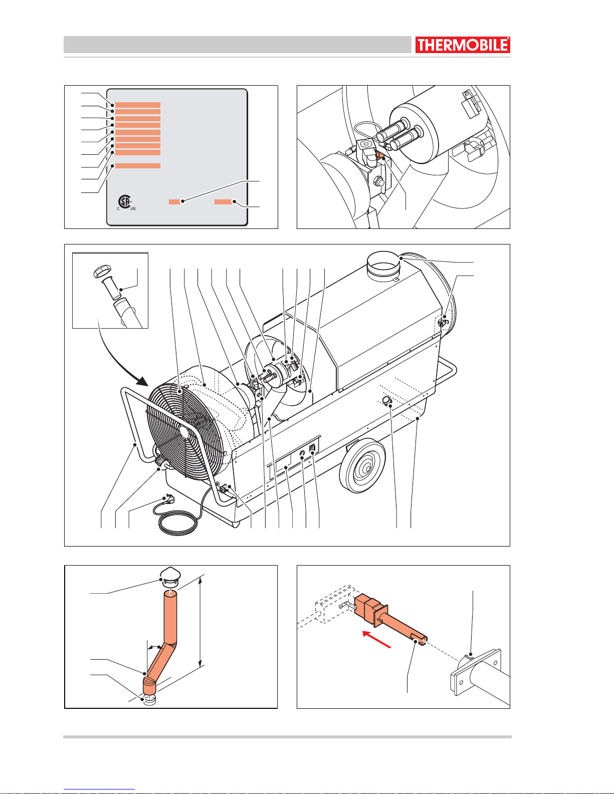
Identification of the product (fig. 1)
The identification plate is attached to the side
of the heater. The identification plate shows
the following data:
A Production code
B Bruto capacity
C Netto capacity
D Pump pressure
EAirflow
F Electrical connection
G Fuel consumption
H Type of fuel
I Air temperature at 65°F
J Serial number
K Year of manufacture
Service and technical support
For information about the heater, please
contact your dealer or the manufacturer.
Make sure you have the type and serial
number of the heater.
Guarantee and liability
For the Guarantee and Liability see the terms
and conditions.
Environment
Note
The heater is made of various metals
and synthetic materials. The heater
also contains electronic parts, which
must be treated as electronic waste.
Please contact your dealer for further
information.

ITA/ITAS-US 40.020.945 - rev. 04 - 2011 7
English
1 SAFETY INSTRUCTIONS
1.1 Pictograms in this manual
1.2 Pictograms on the heater (fig. 2)
A Pump pressure
1.3 Use in conformity with destination
The heater is designed for use on
construction sites, in poultry houses,
workshops, storage rooms, warehouses,
greenhouses and polyurethane tunnels and
to dry agricultural products and bulbs.
1.4 Use this product for the purpose it
was intended for
The convector heater was designed for use
indoors and outdoors. The heater can be
used for the heating of tents, building sites,
showrooms, sports halls, storage sheds,
workshops, round-the-clock projects,
warehouses, greenhouses, polytunnels,
spray arrangements, and for the drying of
agricultural produce and bulbs.
1.5 General instructions
Caution
A caution shows a danger that can
cause damage to the equipment.
Warning
A warning shows a hazard that can
cause death or serious injury.
Warning
When working on the heater for
maintenance or repair works always
disconnect the electric power!
Hot
Some surfaces are hot! Wait until
these parts are cooled down
sufficiently before maintenance is
carried out.
Suggestions and advice for
conducting the relevant tasks or
activities more easily.
Caution
If the heater will be installed indoors,
make sure that there is proper
ventilation in the room. Make sure
the flue gas can only flow to an
outside source separate from the
room.
Warning
• For all service and adjustments
contact qualified, competent and
authorized persons.
• Make sure to always follow the
local standards and guidelines as
well as the local requirements.
• Make sure to read this manual
carefully before using the
convector heater.
• Keep this document near the
convector heater.
• Follow the procedures described.
• Do not lean on the convector
heater.
• Do not tamper with the heater.
Adjustments may only be made
by specially trained personnel.
• Do not operate the unit near
combustibles.
• Keep at least 7 ft away from the
exhaust opening of the convector
heater.
• Make sure there is sufficient air
for proper combustion.
• Make sure there is no highly
flammable material near the
convector heater.
8 40.020.945 - rev. 04 - 2011 ITA/ITAS-US
English
1.6 Additional safety
• The maximum static pressure in the duct
system is 10.44 lb/ft
2
.
• The maximum air temperature of the
ducts is 220 °F.
Warning
• Make sure that the convector
heater has cooled off sufficiently
and that the plug has been
removed from the socket before
carrying out any repair or
maintenance work.
Warning
• Connect the heater only to a
1-phase 120 V / 60 Hz power
supply.
• Replace fuses only with identical
spares.
• The heater must be grounded.
Warning
• Use only No.1 fuel, No.2 fuel or
Diesel.
• Do not use gasoline or crankcase
oils.
• Place the separate fuel tank at
least 7 ft from the heater.
• Do not fill the tank while the
heater operates.
• When the static pressure is not
within the limitation of the heater,
this can cause damage to the fan
motor or heat exchanger.

ITA/ITAS-US 40.020.945 - rev. 04 - 2011 9
English
2 INTRODUCTION
2.1 Purpose
The heaters are indirectly fired heaters with
photocell control and connections for a room
thermostat and flue with raincover.
The heaters are tested at sea level and at a
temperature of 68 °F.
2.2 Working principle
An electric motor drives a fan and fuel pump.
The pump draws the fuel from the tank to a
magnetic valve. The fan blows air into and
around the combustion chamber.
The magnetic valve opens 12 seconds after
switching on the heater and the fuel flows into
the nozzle.
A spark between the electrodes ignites the
atomised fuel and starts a flame. The light
from the flame activates a photocell. After the
safety time the ignition switches off. The
magnetic valve closes when you switch off
the heater, or as a result of a fault, the flame
stops.
The fan runs until a thermostat switches the
fan off: the cooling cycle is complete.
2.3 Main components (fig. 3)
A Fuel tank filter
BGrill
CFan
D Electric motor
E Magnetic valve
F Electrode (2x)
G Burner head
H Air slide valve
I Photocell
J After cooling safety thermostat
K Combustion chamber/heat exchanger
L Flue connection
M Maximum thermostat
N Fuel tank (not for ITAS series)
O Drain plug
POn/Off switch
Q Reset button
R Identification plate
S Air inlet burner (only for ITA 45, ITAS 45)
T Fuel pump
U Connector for room thermostat
V Cable with plug
W Fuel filter
X Push bar frame
2.4 Accessories
• Flue with raincover
• Room thermostat
• Single outlet with duct
• Manifold with duct
• Wheels with tyres (only for ITA 45 and
ITA 75).
3 GETTING STARTED
3.1 Remove packaging
1. Remove the packaging from the heater.
2. Attach the handle and the bumper to the
heater (only for ITA 75).
3.2 Installation
1. Make sure that the heater is placed
horizontally.
2. Fill the tank with fuel.
3. Make sure there is sufficient distance
between the wall and the air inlet.
Minimum distance is 4 ft.
4. Make sure that the heated air can flow
without obstruction. Minimum distance
from outlet to an obstacle is 7 ft.
Caution
Use only No. 1 fuel, No. 2 fuel or
Diesel.
Caution
• Be careful when you fill the tank.
Remove any spilled oil from the
heater and the ground.
• Gas oil tends to thicken at low
temperatures. This can block the
filters. Add a maximum of 15%
paraffin to the fuel at
temperatures below -20 °F, o r
keep the fuel frost-proof, or use
tank heating (optional).
10 40.020.945 - rev. 04 - 2011 ITA/ITAS-US
English
5. Check the ventilation surface area: for
each 3500 BTU a surface of 270 ft
2
is
needed.
6. Check the connection of the room
thermostat.
Do not remove the cap when you do not
use a room thermostat.
Remove the cap to connect a room
thermostat.
7. Install the flue (4 ft and a raincover).
8. Make sure the On/Off switch is in the
0 position.
9. Check the supply voltage: see the
identification plate.
10. Put the plug in the socket.
11. Press the reset switch.
3.3 Power up
1. Press the On/Off switch to switch on the
heater.
2. Set the room thermostat.
The heater supplies warm air after
approximately 10 seconds.
4 OPERATION
4.1 During operation
4.2 Power down
1. Switch off the heater.
The magnet valve closes and stops the
fuel supply.
2. Disconnect the electric power.
Caution
Do not switch on the heater when the
tank is empty!
Caution
The fuel system de-aerates through
the nozzle. Close down may occur
several times when starting with an
empty filter. To rectify: press the reset
switch.
Hot
Do not touch the flue with rain cover,
nor the air outlet! The flue with rain
cover and the air outlet become hot
during operation!
Caution
After you switch off the heater, the
fan still rotates. The fan cools the
heater to avoid damage caused by
overheating. The fan stops
automatically.
Do not remove the plug from the
socket until the heater fully stops!

ITA/ITAS-US 40.020.945 - rev. 04 - 2011 11
English
5 MAINTENANCE
5.1 Maintenance table
After each winter season, record the
maintenance in the table at the back of this
book.
/i
5.2 General
If the heater is not used for a long period:
1. Empty the tank, rinse the tank with
paraffin.
2. Fill the tank with diesel oil, to prevent
corrosion in the tank.
3. Let the heater burn for 3 minutes. This
protects the pump against corrosion.
4. Keep the burner head free from dust and
sediment.
A dirty burner head causes bad
combustion that makes soot and carbon
and damage to the burner chamber.
5.3 Adjustment air inlet and
electrodes (fig. 6)
A Distance nozzle-swivel disc
B Opening air inlet
C Distance nozzle-electrode
D Distance swivel disc-cone
5.4 Electrodes (fig. 7)
Check the electrodes:
1. Remove the cover of the heater.
2. Remove the oil pipe (B).
3. Loosen the electrode cables (A).
Warning
For all service and adjustments
contact qualified, competent and
authorized persons.
Description Period
Yearly Biennial
Empty the tank and rinse the tank with paraffin. X
Clean the filter in the filter cap of the tank. X
Check the photocell for damage. Make sure the photocell is free from
dust and sediment.
X
Check the adjustment of the electrodes. X
Replace the fuel filter. X
Check the nozzle. X
Clean the heat exchanger. X
Hot
Do not touch the flue with raincover
and air outlet! Wait until the flue with
raincover and the air are cooled
down before maintenance.
Warning
Disconnect the electric power during
maintenance.

12 40.020.945 - rev. 04 - 2011 ITA/ITAS-US
English
4. Remove the screws (G).
5. Remove the burner head.
6. Clean and re-adjust the electrodes (C).
The electrodes must be free of dirt,
grease, fuel etc.
If the points of the electrodes are burned
too much and adjustment is impossible:
replace the electrodes.
7. Loosen the screw (F).
8. Re-adjust the electrodes.
Install the burner head in the reverse order.
Replace the electrodes:
1. Do the points 1 to 7 of “Check the
electrodes”.
2. Replace the electrodes.
3. Adjust the electrodes.
Install the burner head in the reverse order.
5.5 Nozzle (fig. 7)
Check the nozzle:
1. Remove the cover of the heater.
2. Remove the oil pipe (B).
3. Loosen the electrode cables (A).
4. Remove the screws (G).
5. Remove the burner head (H).
6. Check the nozzle (D).
If the nozzle is black, because of soot or
coke: replace the nozzle.
Install the burner head in the reverse order.
Replace the nozzle:
1. Do the points 1 to 6 of “Check the
nozzle”.
2. Remove the electrodes (C).
3. Remove the swivel disc (E).
4. Remove the nozzle (D).
5. Replace the nozzle: use the correct type!
6. Install the swivel disc.
7. Readjust the electrodes, see fig. 6.
Install the burner head in the reverse order.
5.6 Photocell (fig. 5)
Check the photocell:
1. Remove the cover of the heater.
2. Remove the photocell out of the holder
pipe (A).
3. Clean the photocell if the glass is
black (B).
If the glass is cracked: the photocell must
be replaced by the dealer.
Install the photocell in the reverse order.
Warning
Do not touch the filter of the nozzle.
This will damage the nozzle.
 Loading...